

Page 1
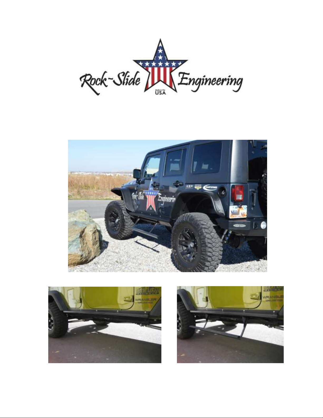
JEEP JK4 STEP SLIDER INSTALLATION
BD-SS-100-JK4
Installation Instruction RSEI 106
Page 2
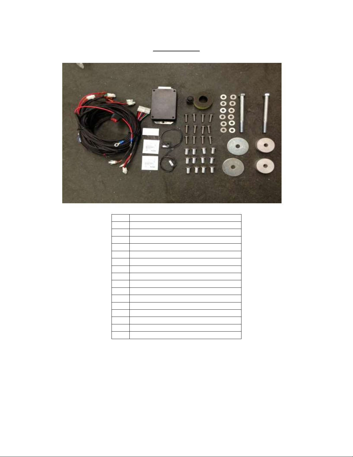
PARTS LIST
QTY
DESCRIPTION
1
Drivers Side Slider Assembly
1
Passenger Side Slider Assembly
1
Wiring Harness and Fuse
1
Double Sided Sticky Squares and Alcohol Pad
1
Cut Off Switch
1
Anti-Seize Packet
1
Control Box
2
Aluminum Spacers
2
Large Washers
2
Grip Tape Strips
2
130mm Bolts
4
Actuating Magnets and Door Sensors
10
7/16” Washers
10
Aluminum Nutserts
10
5/16” SS Button Head Bolts
10
5/16” Stainless Steel Washers
*If any parts listed are missing or damaged please call Rock-Slide Engineering @
*Optional: 2 LED Light Strips
435-752-4580 prior to installation
Installation Instruction RSEI 106
Page 3
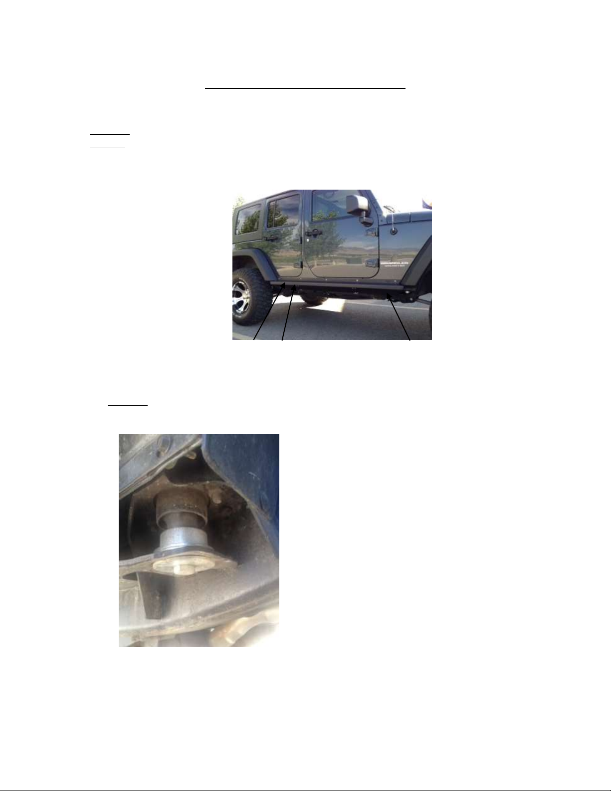
STEP SLIDER INSTALLATION
1) Remove the stock rocker guards if equipped
2) Remove the front body bolts on the driver and passenger side (under the front door)
3) Loosen the rear body bolts (under rear passenger doors)
4) DO NOT REMOVE THESE BOLTS! You will need these bolts to support the slider you are
about to put into place on the Jeep
REAR FRONT
5) Replace the front body bolts on the driver and passenger sides with the 130mm bolt,
aluminum spacer, and large washer in same sequence as the picture below indicates
a) DO NOT completely tighten the bolts, but leave them loose to reflect the same looseness
of the 2 rear bolts so you can fit the slider forks into these slots
6) Move the slider into it’s position on the Jeep
a) You may want some help so that you can support the weight of the slider
b) Take extra care when positioning the slider on the Jeep to prevent any scratching or
marring of the painted surface
Installation Instruction RSEI 106
Page 4

7) Insert the 3 slider forks into the 3 body mount bolt slots
a) The slider should fit tight to the Jeep’s rocker side
8) The top side of the slider should be at a flat 90 degree angle even with the front and rear
wheel wells of the Jeep
9) Tighten all body mount bolts to help bring the slider into position on the Jeep
10) This will be the final position of the slider so verify it’s straight, level, even on both sides
and you are satisfied with the slider’s layout
11) Carefully drill a 7/32’’ pilot hole into the center of the holes on the slider into the Jeep’s
rocker side
**It is extremely important these holes are drilled precisely to insure the slider
will fit properly once the nutserts have been installed
a) The body sides are very thin metal so let the drill bit do the work. Don’t push too hard
on the drill or possible sheet metal damages may occur
12) Loosen the body mount bolts and remove the slider from the Jeep
a) You may want some help so that you can support the weight of the slider
13) From the center of the pilot hole, step up the hole size using a 17/32” bit to create a finish
hole that will be used to install the nutserts
14) Install 5 nutserts per side in the holes that were just drilled into the body of the Jeep
a) We suggest using a crimping tool to optimize the integrity of the nutserts to support the
slider
15) If no crimping tool is available, follow these instructions
a) Install by using a 5/16’’x1.125’’ minimum length bolt with a 3/8’’ nut
b) Put a small amount of grease on the bolt to reduce friction
c) Hold the nut steady with an end wrench so the flange of the insert is flush against the
body panel
d) Tighten the bolt against the nut to crimp the nutsert into place
e) If the nutsert is rotating, place a star-lock washer between the 3/8’’ nut and nutsert
f) Once the nutsert is crimped into place completely back out the bolt
g) If the nutsert ever breaks loose and spins, repeat the process and crimp it tighter to
prevent spinning
(Nutserts that have been installed correctly)
Installation Instruction RSEI 106
Page 5

16) Lift the slider into its final position by inserting the 3 forks on the slider onto the 3 body
mount bolts and aligning it against the Jeep rocker face
17) Make sure the actuator wire is free from being pinched between the frame
18) Attach the slider to the rocker face using the 5/16” button head bolts & washers
19) Start from the center of the slider and work out towards the ends
20) Apply a small amount of anti-seize to the threads of each bolt
21) You will be using 5 bolts/washers per side
a) We recommend tightening the button heads by hand to prevent any damage to the head
of the bolt
22) Tighten the body mount bolts beneath the Jeep to fully secure the slider
23) Make sure the spacer is in between the body and the slider on the front body mount
24) The body mount bolts need to be SNUG to the Jeep frame but DO NOT OVER TIGHTEN the
body mount bolts. Over tightening these bolts could create a friction point causing the
slider to not operate optimally
25) Double check all bolts to verify components and hardware are installed correctly and
securely to the Jeep
***Please note: Expect some variance in parts that may require you to adjust the
tension of bolts to make parts fit correctly and properly. Once all parts are installed,
we suggest then fully tightening all bolts again to fit securely***
If you have any questions please contact Rock-Slide Engineering @ 435-752-4580
WIRING HARNESS INSTALL
Step Slider Wiring Diagram
Driver Side Wire Color Passenger Side Wire Color
Front Door Sensor Orange/Yellow Front Door Sensor Green/Gray
Rear Door Sensor Orange/Pink Door Sensor Blue/White
Driver LED Light Brown/Tan Passenger LED Light Pink/Tan
Driver Actuator Red/Black Passenger Actuator Red/Black
Installation Instruction RSEI 106
Page 6

**WARNING**
REMOVE FUSE FROM WIRING HARNESS PRIOR TO INSTALLATION! CONNECTING
THE HARNESS TO THE POWER SOURCE WITH THE FUSE ATTACHED WILL SHORT
OUT THE WIRING HARNESS
NEVER ALLOW THE DOOR SENSOR TO COME INTO DIRECT CONTACT WITH THE
ACTUATING MAGNET. THIS WILL DESTROY THE SENSOR MAKING IT UNUSABLE
• Remove the “B” pillar covers on both driver and passenger and driver sides
• Roll the carpet back underneath the rear seat to expose the floor boards
• Position the control box under the rear seat on the passenger side
• It’s recommended that you mount the control box under the rear passenger seat
because it’s out of sight and in a secure location so it will not come into contact
with anything or be kicked by a rear seat passenger (see below)
• Plug the harness into the control box and lay the harness wire into position in the Jeep
starting on the rear passenger side
• You will want to divide the harness between the rear seats, the front passenger
seat and finish with the driver door. This will reveal how you will be able to
conceal the harness under the carpet when your done
• Once the harness is positioned in its proposed layout you will need to gain access to the
slider outside the Jeep to power the slider.
• Starting on the rear passenger side, locate the drain plug and drill a small hole into it to
allow you to run the actuator wires to the slider (see below)
• Once the actuator is run to the slider you can put some silicon sealant around
the drilled hole to prevent any elements from entering, but it’s not required
Installation Instruction RSEI 106
Page 7

• Route the actuator wire around the backside of the slider and plug the red/black
connector into the slider
• Actuator wire must be wired around the backside of slider so it’s protected from
the elements and will not be severed off during off-road activity
• Secure wires to minimize slack so they are protected. We recommend zip ties
• *Optional: The pink/tan wire is used if LED light package is being installed
• Inside the Jeep, route the rear passenger door sensor wire along the doorframe; and
using a sticky pad, mount the sensor underneath the door latch
• Connect the blue/white wire to the door sensor
• Place a small piece of electrical tape on the sensor wire to secure (see below)
• While moving to the front passenger door, run the harness along the side of the Jeep’s
tub and route the front passenger door sensor wire up the “B” pillar of passenger door;
and using a sticky pad, mount the sensor underneath the door latch
• Connect the green/grey wire to door sensor
• Place a small piece of electrical tape on the sensor wire to secure
• Returning to the backseat, locate the drain plug on the rear driver side and drill a small
hole into it to allow you to run the actuator wires to the slider
• Once the actuator is run to the slider you can put some silicon sealant around
the drilled hole to prevent any elements from entering, but it’s not required
• Route the actuator wire around the backside of the slider and plug the red/black
connector into the slider
• Actuator wire must be wired around the backside of slider so it’s protected from
the elements and will not be severed off during off-road activity
• Secure wires to minimize slack so they are protected. We recommend zip ties
• *Optional: The brown/tan wire is used if LED light package is being installed
• Route the rear passenger door sensor wire along the doorframe; and using a sticky pad,
mount the sensor underneath the door latch
• Connect the blue/white wire to the door sensor
• Place a small piece of electrical tape on the sensor wire to secure
• Continue to route the harness wires along the lower doorframe on the tub, and just like
performed on the passenger side route the door sensor wire along the “B” pillar up the
doorframe and using another sticky pad, mount the sensor below the door hatch.
• Connect the orange/yellow wire to the door sensor
• Place a small piece of electrical tape on the sensor wire to secure
Installation Instruction RSEI 106
Page 8

• Remove the driver side dash panel and drill a 18mm hole in the panel to accommodate
the cutoff switch
• You can mount the cutoff switch in multiple positions. We recommend the dash
panel simply for the ease off access (see below)
• Mount the ground from the cutoff switch to a metal surface behind dash panel (below)
• Route the cutoff switch wires by running the POS+ and NEG- wires up the driver side
“A” pillar and plug them into the back of the cutoff switch
• Route the remaining POS+ and NEG- wires through the firewall on the driver’s side into
the engine compartment.
• Make sure there is NO INTERFERENCE with any of the pedal linkage under the
dash
• Route these wires along the firewall up to the battery compartment
• Secure the wires using the harness attached to the firewall
• Attach the NEG- to the NEG- side of the battery
• Attach the POS+ to the POS+ side of the battery
• Position the actuating magnets on the catch side of each door
• Make sure the actuating magnets are in perfect line with the sensors
• **DO NOT allow the magnet and sensor to come into direct contact. This
will destroy the sensor making it unusable**
Installation Instruction RSEI 106
Page 9

• Once that proper placement is achieved we recommend using a permanent
marker to outline the magnet on the door.
• Re-check all wires to make sure they are completely secure and free from coming into
contact with any moving part to prevent system damage due to a cut wire
• Reinstall all internal plastic and carpet pieces that were removed.
• Make sure that all wires are tucked back and out of heavy traffic areas on the floor.
• Route them toward the furthest back area underneath the rear seat
• Close all doors
• Insert the fuse into the holder on the POS+ side of the battery
• Test all doors to make sure the step deploys each time a door is opened, and retracts
when the door is closed
MAINTENANCE OF THE STEP SLIDER
• Please note the slider is a mechanical mechanism that requires maintenance to operate
properly. To keep the slider operating at an optimal level it needs to be maintained
with lubrication. We recommend using a Teflon based lubrication on the 7 indicated
points below to keep the slider operating smoothly. A good rule of thumb is every
month. Heavy trail use will increase the frequency in lubrication.
LUBRICATE THE HINGE POINTS:
2- HINGE POINTS ON THE STEP PORTION ON THE BACK SIDE
4-HINGE POINTS IN THE BODY OF THE SLIDER (ALUMINUM BLOCKS)
1-LUBRICATE THE MOTOR SHAFT LIGHTLY SO IT CAN TRANSFER THE
LUBRICANT TO THE O-RINGS AS IT RETRACTS
Installation Instruction RSEI 106
Page 10

TROUBLE SHOOTING/FRICTION POINTS
• The slider is powered by the Jeep’s battery when engine is off and powered by the Jeep’s
engine while the vehicle is running. This will cause the slider to operate at different
speeds depending on the Jeep engine is running or not.
• If you feel the slider is sticking at certain points or the motor is stressing it may be
possible a friction point has developed during the install due to a variance in the slider
or Jeep construction
• To identify a friction point that may be stressing the slider motor, look at the
slider from outside the jeep and open and shut the Jeep door a couple of times
and study the way the slider operates. Look at the slider for wear in the powder
coating. The slider leaves our manufacturing facility with a perfect powder
coating so if you see a spot on the slider that has scratches or the powder coating
shows a blemish; that’s a good indication of a friction point. Using a file or other
grinding tool to smooth over a small area on the slider can alleviate this
problem.
Thank you for choosing Rock-Slide Engineering products. We value your business and
welcome your feedback/suggestions. If you have any concerns please contact us directly at
435-752-4580. We are here to help you!
Installation Instruction RSEI 106
 Loading...