

Page 1
RSE Step/Slider Installation Instructions:
Full Sized Ford
Van
Thank you for your purchase of the finest engineered step/slider on the market. The
step/slider units are preassembled and adjusted in our factory to make installation easy,
but a few simple points must be observed for ease of installation and operation:
1. Disconnect battery ground before installation.
2. The assembled step/sliders are very large and heavy requiring two people for
installation.
3. Itʼs very important that the step sliders do not twist when bolted to the mounting
supports.
Begin by thoroughly reading these instructions and identifying the components included
with your kit.
Part 1: Step/slider assembly
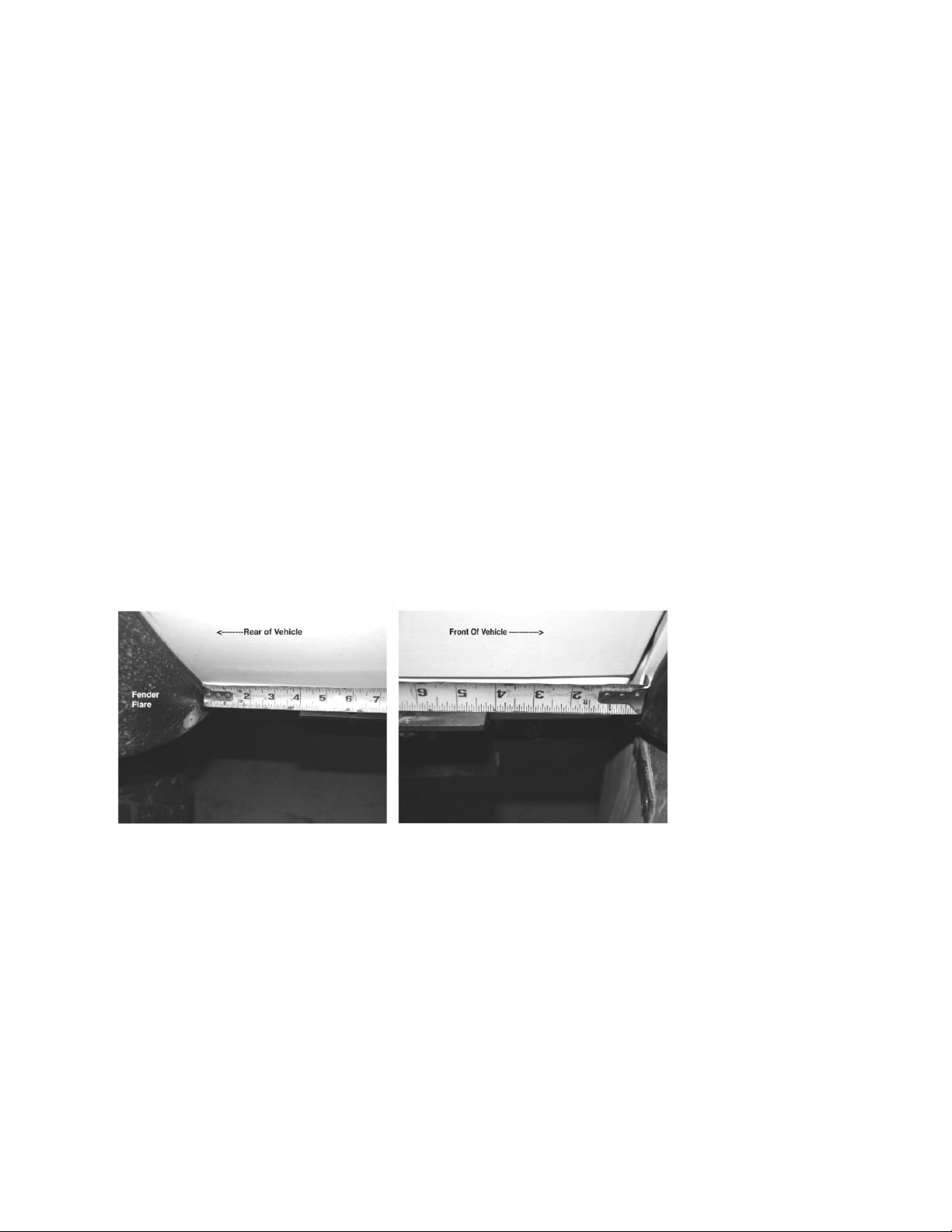
Step 1: Position upper support bracket as shown (fig. 1).
Fig 1.
It should be centered between the fenders or fender flares if so equipped. Hold the
support bracket in place and mark the hole locations for the threaded inserts used to
mount the support to the body of the vehicle. The welded threaded inserts on the support
bracket should be horizontal Make sure the support is where you want it: too high and the
doors may scrape on the step/sliders, and too low the step/sliders will be at the wrong
angle to mount to the lower support.
installation
Step 2: Center-punch all the threaded insert holes and pre-drill with small bit. A step drill
bit is an excellent tool for cutting large holes for the threaded inserts.
1
Page 2

Fig. 2
Use touch-up paint to coat any exposed metal. Silicone sealant can also be used to seal
the threaded inserts to the body of the vehicle. Use a large threaded insert installation
tool—body shops usually have them— (fig. 2).
Itʼs very important the threaded inserts are perfectly
installed. If cocked or distorted they may pull out of
the thin sheet metal causing hard to repair damage.
If not
Fig 2.
satisfied with the insertʼs installation, they can be drilled out and replaced.
Step 3: Coat the threads of the 5/16”x1” bolts with silicone and bolt the upper support
bracket to the body of the vehicle..
Step 4: Rest the step/slider assembly on the upper support bracket and hold loosely in
place with two 5/16x1” button head stainless steel bolts provided.
Step 5: Place ʻLʼ shaped lower support bracket under the step/slider assembly and
loosely attach to step/slider assembly with two 5/16x1” bolts supplied. The lower support
bracket should be on the inside—towards the center of the vehicle—of the pinch weld.
Step 6: With assistance, hold the step/slider where it needs to be—sliding lower support
bracket if necessary so it will have full contact with the pinch weld AND have full contact
with the step/slider assembly AND align with the holes in the step/slider assembly. Mark
through the holes in the lower support to the pinch weld and remove lower support
bracket.
Step 7: Center-punch and drill 11/32” holes through pinch weld. Coat any exposed bare
metal with paint or silicone to prevent rust. Reinstall lower support bracket except this
time with it on the outside of the pinch weld, (fig. 3) and bolt loosely with supplied 5/16x1”
bolts making sure the lower support maintains contact with step/slider assembly.
2
Page 3
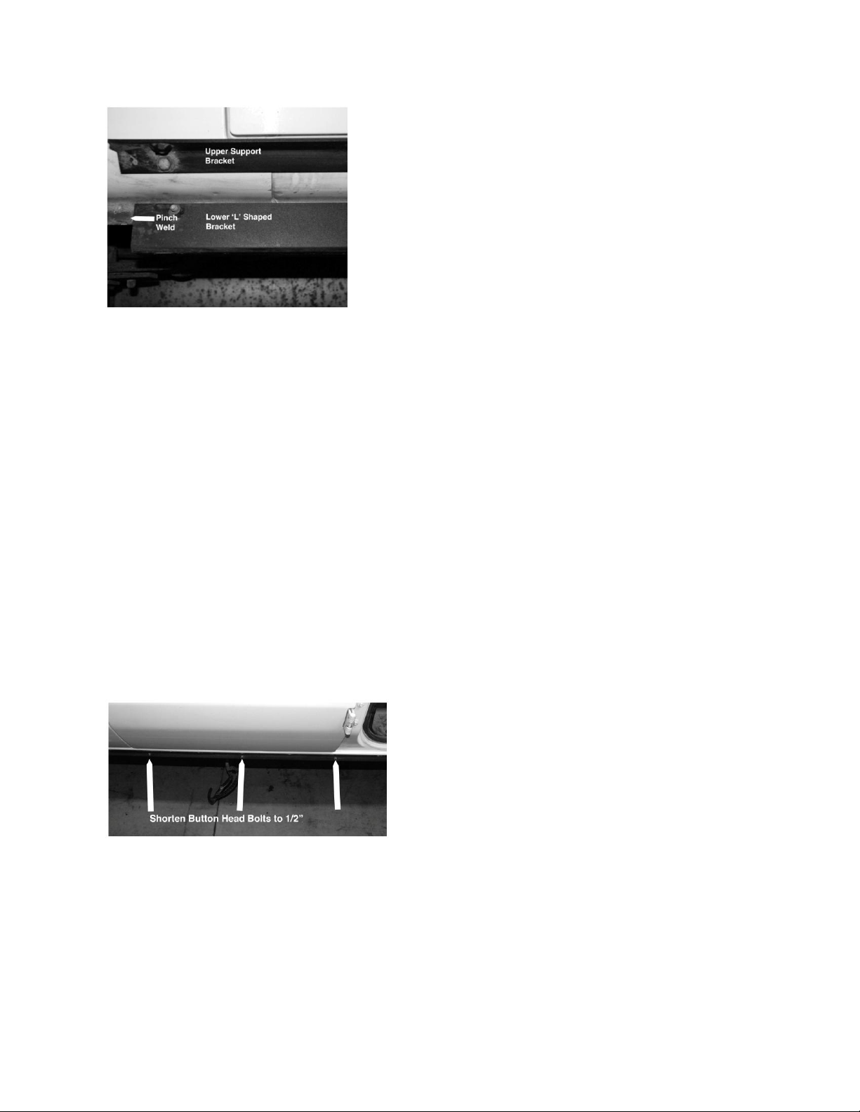
Fig. 3
Step 8: How does it look? Some fine tuning to fit the step/slider assembly to the body can
be done at this point. Remove step/slider assembly and tighten the lower support bracket
to pinch weld bolts.
Step 9: Check all bolts for tightness and, with assistance, loosely install step/slider
assembly using 5/16x1” button head stainless steel bolts with stainless washers to the
upper support.
*NOTE: Be sure to feed servo motor wires through the supplied holes in the lower
support bracket before bolting step/slider to upper support bracket.
*NOTE: Make sure no wires are being pinched between the step/slider assembly and
either support bracket.
*NOTE: Some of the button head bolts will have to be shortened to 1/2” in order to clear
the internal step mechanism (See arrows fig. 4).
fig. 4
Step 10: Loosely install lower support bracket bolts along the bottom of the step/slider.
The step/slider assembly should contact the lower support all along its length. If it
doesnʼt, shims can be used to make up any difference. Note: If there are gaps between
3
Page 4

step slider assembly and lower support, just bolting the unit tightly to the lower support
can cause twisting and effect operation of the step. Leave mounting bolts loose and
repeat procedure for other side.
Part 2: Electrical
Installation
Wiring your new step/sliders is very simple. Only a constant +12volt and ground are
required. Some Ford vans have a battery under the floor, or in the case of a Sportsmobile
the relay for the on-board air compressor is an excellent source of constant 12v power.
Step 1: Remove inline fuse. Lay the included wiring harness out to get an idea where
everything goes. Pull up the factory interior step panels to expose an excellent location
for the CPU and to pull wires through to the underside of vehicle (fig 5).
Fig. 5
Step 2: Determine which door switches go where, and clean the location in the door jamb
with alcohol to promote adhesion (fig. 6). Affix the front door switches below the catch
hoop and the side door switch inside the lower hinge in the forward door jamb (fig. 6 & 7)
Fig. 6 Fig. 7
4
Page 5

Step 3: Install magnets onto the front doors directly across from the electronic switch unit
and slowly close the door to make sure it is aligned and does not touch the switch unit or
any other obstruction. Install magnet opposite side door switch in the same manner.
Step 4: Pull away door seal and run the switch wires under them and into the area under
the step panel removed in step 1.
Step 5: Run wires for the on/off switch from under the step panel under the door seal to
behind the driverʼs side lower knee panel. Install switch in panel (fig 8), and turn off.
Fig 8
Part 3: Testing and
Finishing
Step 1: Snug down all the button head bolts on top of the step/sliders. Check the fit
between step/slider assembly and lower bracket. Is there contact all along the length of
the step/slider? If not, place shims between lower support and step/slider assembly.
Snug the lower bolts.
Step 2: Connect battery ground, install fuse, activate switch and close all doors . Wait a
few seconds for the CPU to boot and open the driverʼs door. The step should deploy
smoothly without binding. If not, close the door and let the CPU boot once again. Check
operation for passenger side by opening and closing front and side doors. Both should
operate the passenger side step.
Step 3: If the steps are working well, tighten all the mounting bolts top and bottom and
retest step operation. If the step deployment is no longer smooth or if they donʼt close
flush, the step/slider may have twisted a bit and will need shimming between lower
support bracket and step/slider assembly.
Step 4: Carefully route, support and hide all of the associated wiring making sure none of
it is touching the exhaust or anything sharp. Replace inner step panels.
5
 Loading...