

Rockford Fosgate SSC-500 Installation Manual
INSTALLATION MANUAL FOR
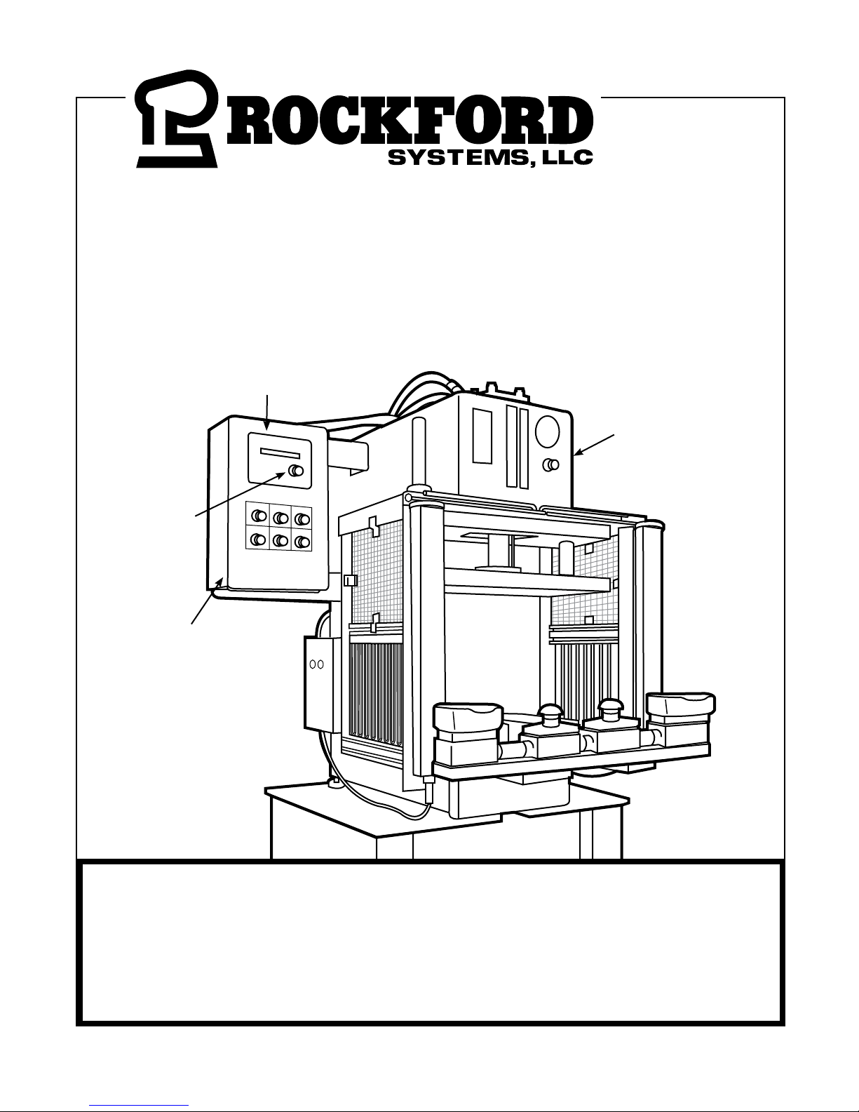
SSC-500 CONTROL SYSTEMS
ON HYDRAULIC PRESSES
Operator Interface
Keypad/Display
SSC-500 Control Box
Program/Run
Selector Switch
(Not Shown)
Remote Operator
Station (Optional)
IMPORTANT: PLEASE REVIEW THIS ENTIRE
PUBLICATION BEFORE INSTALLING, OPERATING OR
MAINTAINING THE SOLID-STATE HYDRAULIC PRESS
ELECTRICAL CONTROL SYSTEM.
5795 Logistics Parkway • Rockford, Illinois 61109 • Toll Free 1-800-922-7533 (USA only) • Phone (815) 874-7891
Fax (815) 874-6144 • Web Site: www.rockfordsystems.com • E-Mail: sales@rockfordsystems.com
Manual No. KSL-249

TABLE OF CONTENTS
SSC-500 Hydraulic Press Solid-State Control
SECTION 1—IN GENERAL ..................................................3 - 9
SE CTION 2—INTRODUCTION .........................................10 - 14
SE CTION 3—INSTALLATION OF SSC-500 CONTROL SYSTEM
COMPONENTS ............................................................14 - 24
Literature Packetr ...................................................... 14 - 15
Control Box ............................................................... 15 - 18
P alm Button Assembly ............................................... 18 - 20
Foot Switch (Optional) ........................................................20
Supervisory Control Station ................................................21
Presence Sensing Device ...................................................21
Main Power Disconnect Switch ..........................................22
Motor Starter ....................................................................22
Custom or Special Control Box ...........................................22
Flywheel and Gear Covers ..................................................22
Collateral Equipment ..........................................................22
Point-of-Operation Safeguards ...........................................22
Other Installation Considerations .................................23 - 24
SECTION 4—PROGRAMMING ........................................24 - 33
Setup of Control System .......................................................24
Initial Setup Procedure ........................................................24
Programming Overview .........................................................25
Clear Stroke ......................................................................26
Clear Batch .......................................................................27
Batch Preset .....................................................................27
Bottom Dwell ....................................................................28
Decompress Timerl ...........................................................28
Anti-tiedown ms ................................................................29
Single Return Mode ...........................................................28
Asing tmr sec ....................................................................29
PSDI Timer........................................................................30
Asing Mode.......................................................................30
Asing Timer ......................................................................31
User Inputs ...............................................................31 - 32
Options edit ......................................................................33
SECTION 5—PSDI ....................................................................34
SECTION 6—OPERATING CONSIDERATIONS ..............................35
SECTION 7—FAULT MESSAGES ....................................36 - 37
SECTION 8—MAINTENANCE & INSPECTION ..................... 38 - 39
SE CTION 10—LAYOUT SKETCH ...............................................42
SE CTION 11—RETURN AUTHORIZATION FORM ......................43
SE CTION 12—ORDER FORM ....................................................44
FIGURES, PHOTOS, AND TABLES
Figure 2.1 Block Diagram ........................................................12
Figure 4.1 Initial Setup Procedure Flowchart .............................24
Figure 4.2 Initial Information on Display ....................................24
Figure 4.3 Main Program Menu Flowchart ................................25
Figure 4.4 Clear Stroke Flowchart ............................................26
Figure 4.5 Clear Batch Flowchart .............................................26
Figure 4.6 Batch Preset Flowchart ............................................27
Figure 4.7 Bottom Dwell Flowchart ...........................................27
Figure 4.8 Anti-tiedown Flowchart ............................................28
Figure 4.9 Asingle Mode Flowchart ..........................................28
Figure 4.10 Asingle Tmr Flowchart ...........................................29
Figure 4.11 User Input Fault Messages Chart ............................29
Figure 4.12 Input # 1 - 4 Flowchart .........................................30
Figure 4.10 Speed Change Flowchart .......................................31
Photo 1.1 Inside view of Control box ...........................................8
Photo 1.2 Control box with danger labels ....................................9
Photo 3.1 Standard control box with keypad/display .....................15
Photo 3.2 Inside view of standard control box ...........................15
Photo 3.3 Top view of control module with cover.......................16
Photo 3.4 Top view of control module without cover ....................16
Photo 3.5 Operator interface keypad .........................................17
Photo 3.6 Back side of keypad/display ......................................18
Photo 3.7 Palm button assembly ..............................................18
Photo 3.8 Red emergency stop palm button ..............................19
Photo 3.9 Yellow emergency return inch up ..............................20
Photo 3.10 Prior-action pushbutton stations ..............................20
Photo 3.11 Foot switch ............................................................20
Photo 3.12 Supervisory control station ......................................21
Photo 7.1 Main EPROM ...........................................................36
Table 3.1 Depth Penetration Factor ..........................................21
Table 4.1 Quick Reference Table ..............................................25
Table 6.1 Fatal Fault Messages ....................................... 33 - 34
Table 6.2 General Fault Messages ...........................................34
SECTION 9—METHODS OF SAFEGUARDING ...................... 40 - 41
© 2019 Rockford Systems, LLC All rights reserved. Not to be reproduced in whole or in part without written permission. Litho in U.S.A.
2 Call: 1-800-922-7533
Rockford Systems, LLC
DANGER
Safety Precautions
DANGER
SECTION 1 — IN GENERAL
SSC-500 Hydraulic Press Solid-State Control
“ ”
Danger is used to indicate the presence of a hazard which WILL cause SEVERE
personal injury if the warning is ignored.
“ ”
THIS SAFETY ALERT SYMBOL IDENTIFIES IMPORTANT SAFETY MESSAGES IN THIS MANUAL.
WHEN YOU SEE THIS SYMBOL , BE ALERT TO THE POSSIBILITY OF PERSONAL INJURY, AND
CAREFULLY READ THE MESSAGE THAT FOLLOWS.
Efficient and safe machine operation depends on the development, implementation and enforcement of a safety program. This program requires,
among other things, the proper selection of point-of-operation guards and safety devices for each particular job or operation and a thorough safety
training program for all machine personnel. This program should include instruction on the proper operation of the machine, instruction on the
point-of-operation guards and safety devices on the machine, and a regularly scheduled inspection and maintenance program.
Rules and procedures covering each aspect of your safety program should be developed and published both in an operator’s safety manual, as
well as in prominent places throughout the plant and on each machine. Some rules or instructions which must be conveyed to your personnel and
incorporated into your program include:
DANGER
Never place your hands or any part of your body in this machine.
Never operate this machine without proper eye, face and body protection.
Never operate this machine unless you are fully trained, instructed, and you have read the instruction manual.
Never operate this machine if it is not working properly—stop operating and advise your supervisor immediately.
Never use a foot switch to operate this machine unless a point-of-operation guard or device is provided and
properly maintained.
Never operate this machine unless two-hand trip, two-hand control or presence sensing device is installed at the proper
safety distance. Consult your supervisor should you have any questions regarding the proper safety distance.
Never tamper with, rewire or bypass any control or component on this machine.
A company’s safety program must involve everyone in the company, from top management to operators, since only as a group can any operational
problems be identified and resolved. It is everyone’s responsibility to implement and communicate the information and material contained in catalogs
and instruction manuals to all persons involved in machine operation. If a language barrier or insufficient education would prevent a person from
reading and understanding various literature available, it should be translated, read or interpreted to the person, with assurance that it is understood.
FOR MAINTENANCE AND INSPECTION ALWAYS REFER TO THE OEM’s (ORIGINAL EQUIPMENT
MANUFACTURER’S) MAINTENANCE MANUAL OR OWNER’S MANUAL. If you do not have an owner’s
manual, please contact the original equipment manufacturer.
Rockford Systems, LLC
Call: 1-800-922-7533 3

SECTION 1 — IN GENERAL
SSC-500 Hydraulic Press Solid-State Control
Safety References
OSHA’S ACT AND FEDERAL REGULATIONS
Since the enclosed equipment can never overcome a mechanical deficiency, defect or malfunction in the machine itself, OSHA (Occupational
Safety and Health Administration) has established certain safety regulations that the employers (users) must comply with so that the machines
used in their plants, factories or facilities are thoroughly inspected
and are in first-class operating condition before any of the enclosed
equipment is installed.
1. An Act – Public Law 91 - 596, 91st Congress, S. 2193,
December 29, 1970
Duties:
Sec. 5. (a) Each employer —
(1) shall furnish to each of his employees employ-
ment and a place of employment which are free from recognized hazards that are causing or are likely to cause death or
serious physical harm to his employees;
(2) shall comply with occupational safety and health standards
promulgated under this Act.
(b) Each employee shall comply with occupational safety and
health standards and all rules, regulations, and orders issued
pursuant to this Act which are applicable to his own actions
and conduct.
2. OSHA’s Code of Federal Regulations, Subpart O, that an
employer (user) must comply with include:
Section 1910.211 Definitions
Se ction 1910.212 (a) General Requirements for all Machines
Section 1910.217 Mechanical Power Presses
Se ction 1910.219 (b)(1) Mechanical Power-Transmission Apparatus
(Flywheel and Gear Covers)
3. OSHA’s 29 Code of Federal Regulations, Subpart J 1910.147
The Control of Hazardous Energy (Lockout / Tagout)
4. OSHA’s Publications
“General Industry Safety and Health Regulations Part 1910,” Code
of Federal Regulations, Subpart O
“Concepts and Techniques of Machine Safeguarding,” OSHA 3067,
Revised 1992
These publications can be obtained by contacting:
Superintendent of Documents
US Government Printing Office
P.O. Box 371954
Pittsburgh, PA 15250-7954
Phone: (202) 512-1800
Fax: (202) 512-2250
www.gpo.gov
ANSI SAFETY STANDARDS FOR MACHINES
The most complete safety standards for machine tools are published
in the ANSI (American National Standards Institute) B11 series. The
following is a list of each ANSI B11 Standard available at the printing
of this publication.
B11.1 Mechanical Power Presses
B11.2 Hydraulic Presses
B11.3 Power Press Brakes
B11.4 Shears
B11.5 Iron Workers
B11.6 Lathes
B11.7 Cold Headers and Cold Formers
B11.8 Drilling, Milling and Boring
B11.9 Grinding Machines
B11.10 Sawing Machines
B11.11 Gear Cutting Machines
B11.12 Roll Forming and Roll Bending
B11.13 Automatic Screw/Bar and Chucking
B11.14 Coil Slitting Machines
B11.15 Pipe, Tube and Shape Bending
B11.16 Metal Powder Compacting Presses
B11.17 Horizontal Hydraulic Extrusion Presses
B11.18 Coil Processing Systems
B11.19 Performance Criteria for the Design, Construc-tion, Care
and Operation of Safeguards as Referenced in the Other
B11 Machine Tool Safety Standards
B11.20 Safety Requirements for Manufacturing Sys-tems/Cells
B11.21 Lasers
B11.22 CNC Turning Machines
B11.23 Machining Centers
B11/TR1 Ergonomic Considerations for the Design, Installation and
Use of Machine Tools
B11/TR2 Mist Control
B11/TR3 Hazard ID and Control
B11/TR4 Control Reliability
R15.06 Robotic Safeguarding
These standards can be purchased by contacting:
American National Standards Institute, Inc.
11 West 42nd Street
New York, New York 10036
Phone: (212) 642-4900
Fax: (212) 302-1286
www.ansi.org
OR
Association of Manufacturing Technology (AMT)
7901 Westpark Drive
McLean, Virginia 22102
Phone: (703) 827-5211
Fax: (703) 893-1151
www.mfgtech.org
4 Call: 1-800-922-7533
(Continued on next page.)
Rockford Systems, LLC

SECTION 1 — IN GENERAL
SSC-500 Hydraulic Press Solid-State Control
NATIONAL SAFETY COUNCIL SAFETY MANUALS AND DATA
SHEETS
Other good references for safety on machine tools are the National
Safety Council’s Safety Manuals and Data Sheets. These manuals and
data sheets are written by various committees including the Power
Press, Forging and Fabricating Executive Committee. Copies of the
following publications are available from their library:
Manuals
Power Press Safety Manual - 4th Edition
Safeguarding Concept Illustrations - 6th Edition
Forging Safety Manual
Data Sheets
Bench and Pedestal Grinding Wheel Operations 12304-0705
Boring Mills, Horizontal Metal 12304-0269
Boring Mills, Vertical 12304-0347
Coated Abrasives 12304-0452
Cold Shearing Billets and Bars in the Forging Industry
12304-0739
Degreasing (Liquid), Small Metal Parts 12304-0537
Dies, Setup and Removal of Forging Hammer 12304-0716
Drill Presses, Metalworking 12304-0335
Drills, Portable Reamer 12304-0497
Drop Hammers, Steam 12304-0720
Electrical Controls for Mechanical Power Presses 12304-0624
Forging Hammer Dies, Setup and Removal of 12304-0716
Forging Presses, Mechanical 12304-0728
Gear-Hobbing Machines 12304-0362
Handling Materials in the Forging Industry 12304-0551
Kick (Foot) Presses 12304-0363
Lathes, Engine 12304-0264
Milling Machines, Metalworking 12304-0364
Planers, Metal 12304-0383
Power Press (Mechanical) Point-of-Operation Safeguarding, Concepts of
12304-0710
Power Press Point-of-Operation Safeguarding: Two-Hand Control and
Two-Hand Tripping Devices 12304-0714
Power Press Point-of-Operation Safeguarding: Type A and B Movable Barrier
Devices 12304-0712
Power Press Point-of-Operation Safeguarding: Point-of-Operation Guards
12304-0715
Power Press Point-of-Operation Safeguarding:
Presence Sensing Devices 12304-0711
Power Press Point-of-Operation Safeguarding:
Pullbacks and Restraint Devices 12304-0713
Power Presses (Mechanical), Inspection and
Maintenance of 12304-0603
Power Presses (Mechanical), Removing Pieceparts
from Dies in 12304-0534
Power Press, Setting Up and Removing Dies 12304-0211
Press Brakes 12304-0419
Robots 12304-0717
Saws, Metal (Cold Working) 12304-0584
Shapers, Metal 12304-0216
Shears, Alligator 12304-0213
Shears, Squaring, Metal 12304-0328
Upsetters, 12304-0721
Copies of these manuals and data sheets can be obtained by contacting:
National Safety Council
1121 Spring Lake Drive
Itasca, IL 60143-3201
1-800-621-7619 ext. 2199
Fax: (630) 285-0797
www.nsc.org
OTHER SAFETY SOURCES
National Institute of Occupational Safety and Health (NIOSH)
4676 Columbia Parkway
Cincinnati, OH 45226
Phone: (513) 533-8236
Robotic Industries Association (RIA)
P.O. Box 3724
Ann Arbor, MI 48106
Phone: (734) 994-6088
www.robotics.org
For additional safety information and assistance in devising,
implementing or revising your safety program, please contact the
machine manufacturer, your state and local safety councils, insurance
carriers, national trade associations and your state’s occupational
safety and health administration.
Warranty, Disclaimer and Limitation of Liability
Rockford Systems, LLC warrants that this product will be free from defects in material and workmanship for a period of 12 months from the date of shipment
thereof. ROCKFORD SYSTEMS LLC’S OBLIGATION UNDER THIS WARRANTY IS EXPRESSLY AND EXCLUSIVELY LIMITED to repairing or replacing such products
which are returned to it within the warranty period with shipping charges prepaid and which will be disclosed as defective upon examination by Rockford
Systems, LLC This warranty will not apply to any product which will have been subject to misuse, negligence, accident, restriction and use not in accordance
with Rockford Systems, LLC’s instructions or which will have been altered or repaired by persons other than the authorized agent or employees of Rockford
Systems, LLC Rockford Systems, LLC’s warranties as to any component part is expressly limited to that of the manufacturer of the component part.
DISCLAIMER
The foregoing Warranty is made in lieu of all other warranties, expressed or
implied, and of all other liabilities and obligations on the part of Rockford
Systems, LLC, including any liability for negligence, strict liability, or otherwise,
and any implied warranty of merchantability or fitness for a particular purpose
is expressly disclaimed.
Rockford Systems, LLC
Call: 1-800-922-7533 5
WARRANTY
LIMITATION OF LIABILITY
Under no circumstances, including any claim of negligence, strict liability, or otherwise,
shall Rockford Systems, LLC be liable for any incidental or consequential damages, or
any loss or damage resulting from a defect in the product of Rockford Systems, LLC
(Continued on next page.)
SECTION 1 — IN GENERAL
SSC-500 Hydraulic Press Solid-State Control
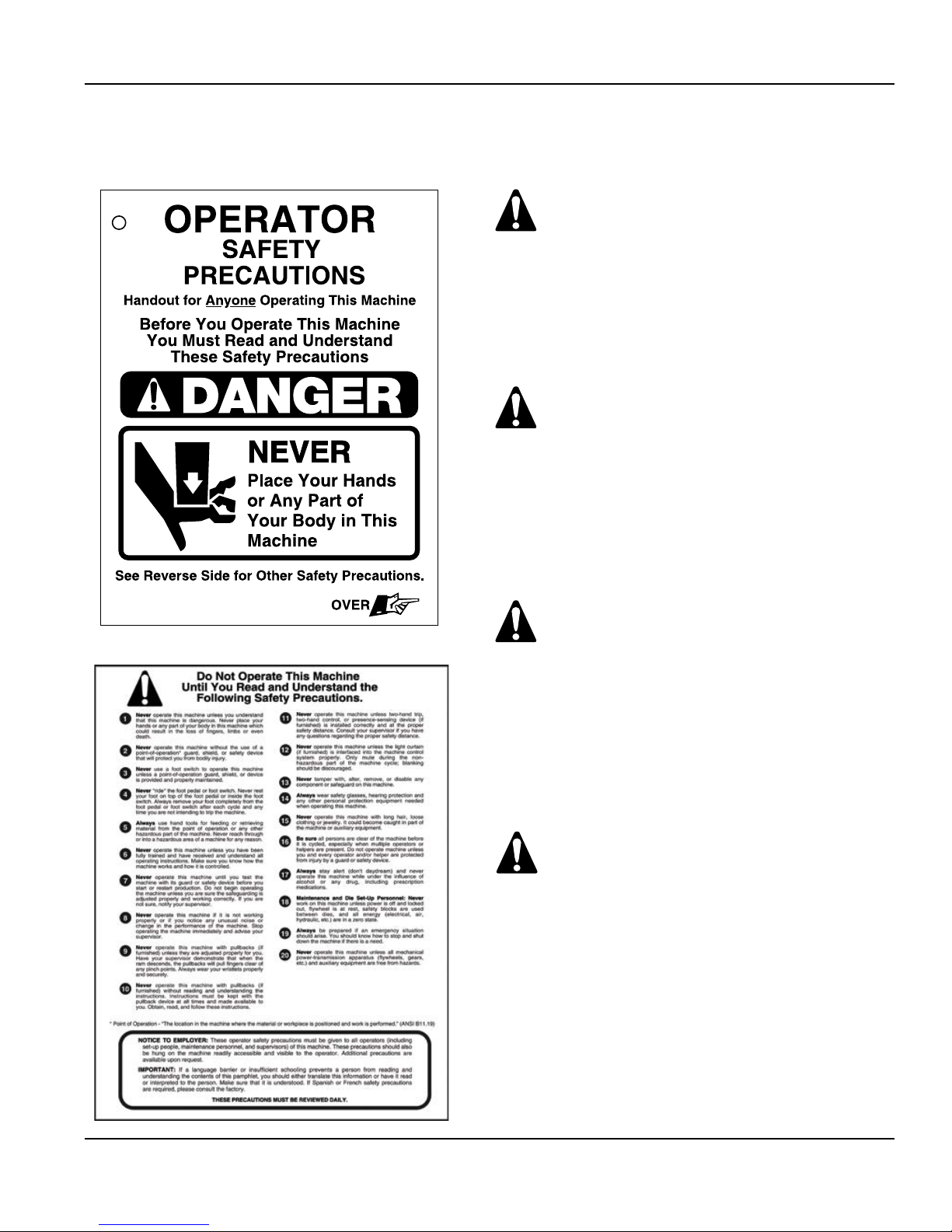
Operator Safety Precaution Pamphlet - (Attachment for machine operators)
Accompanying this equipment is an 8-1/2” x
11” operator safety precaution pamphlet, Part
No. KSC-000, for anyone operating the machine
where this equipment will be installed. This
precaution pamphlet is to be given to all operators, including setup people, maintenance
personnel and supervisors.
This pamphlet should also be attached to the
machine, readily accessible and visible to the
operator. (A hole in the corner of this precaution pamphlet is provided for attaching purposes.) Additional copies of this precaution
are available. Please call, e-mail, write, fax,
or use the order form found on a later page in
this manual.
Part No. KSC-000
Front
When a language barrier or insufficient education prevents a person from reading or
understanding the contents of this operator
safety precaution pamphlet, you should either
translate this information or have it read or
interpreted to the person. Make sure that the
person understands the information. To order
this pamphlet in Spanish, use Part No. KSC000S; in French, use Part No. KSC-000F.
This precaution pamphlet must be reviewed daily.
Back
6 Call: 1-800-922-7533
(Continued on next page.)
Rockford Systems, LLC
SECTION 1 — IN GENERAL
OPERATOR
SAFETY PRECAUTIONS
Handout for Anyone Operating This Machine
SSC-500 Hydraulic Press Solid-State Control
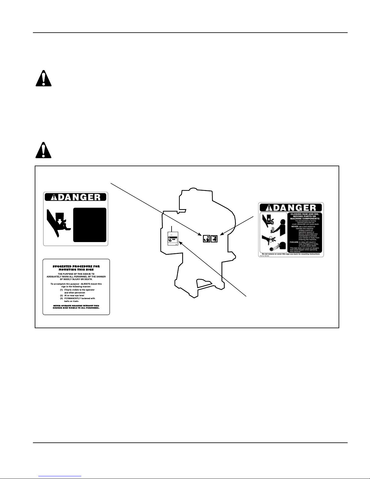
Danger Sign(s) to be Mounted on Machine
Accompanying this equipment is a 5” x 6” polyethylene danger sign, Part No. KSC-054. This sign MUST BE PERMANENTLY
MOUNTED IN A PROMINENT LOCATION on the machine where this equipment is installed. This sign must be in a LOCATION
THAT IS EASILY VISIBLE to the operator, setup person, or other personnel who work on or around this machine. ALWAYS
mount this sign with screws or rivets when installing the enclosed equipment. If a foot switch is ordered, a 5” x 6”
polyethylene danger sign, Part No. KSC-055 is provided. This sign must also be mounted according to the above instructions.
If any danger sign becomes destroyed or unreadable, the sign must be replaced immediately. Contact factory for replacement danger sign(s).
Never operate this machine unless the danger sign(s) is in place.
Part No. KSC-054 Danger Sign - Standard
Part No. KSC-054S - Spanish
Part No. KSC-054F - French
CLOSING RAM AND DIE
Do not remove or cover this sign–see back for mounting instructions
Part No. KSC-054
You are exposed to moving
machine parts that can crush,
dismember and cause death.
DO NOT operate this machine with out safeguards in place.
NEVER place your hands or any
part of your body in this
machine.
FAILURE to obey will result in loss
of fingers or limbs, or
could cause death.
This sign does not cover all dangers that
could happen while operating this machine
.
Front Side
Reverse Side
OPERATOR
SAFETY PRECAUTIONS
Handout for Anyone Operating This Machine
Before You Operate This Machine
You Must Read and Understand
These Safety Precautions
DANGER
Place Your Hands
or Any Part of
Your Body in This
Machine
See Reverse Side for Other Safety Precautions.
SIGN NO. KSC-000
Part No. KSC-055 Danger Sign
(Foot) - Standard
Part No. KSC-055S - Spanish
Part No. KSC-055F - French
OVER
Front Side
See page 6 for
details on this
pamphlet.
“Mechanical Power Press Safety” Booklet
A copy of Booklet No. MPPS (“Mechanical Power Press Safety”) is available upon request. This booklet is copied verbatim from the CFR (Code
of Federal Regulations) and contains all relevant sections of the OSHA Regulations concerning power presses with which an employer (user) must
comply. The enclosed equipment must be installed, used and maintained to meet these regulations. Specifically, any time a foot switch is used,
a suitable point-of-operation safeguard or device must be used to prevent bodily injury. In addition, every press must be provided with
a point-of-operation safeguard! Please review this booklet and the appropriate ANSI (American National Standards Institute) Safety Standard
before installing the enclosed equipment. If you are unfamiliar with these detailed safety regulations, which include regulations on safeguarding the
point of operation properly, you may want to attend our regularly scheduled machine safeguarding seminar. To obtain detailed information about
this training seminar, please call, fax, write, or check our web site. Our address, telephone, fax number, and web site address are on the front
cover of this manual.
Rockford Systems, LLC
Call: 1-800-922-7533 7
(Continued on next page.)
SECTION 1 — IN GENERAL
SSC-500 Hydraulic Press Solid-State Control
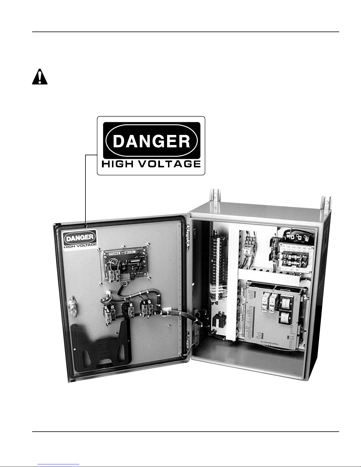
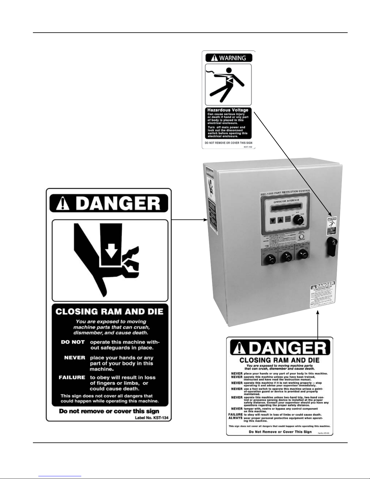
Danger and Warning Labels Provided on Control Box
The illustrated danger and warning labels are affixed to all control boxes provided. All personnel operating or
working around the machine, where this control box is installed, must be required to read, understand and
adhere to all dangers and warnings. If any of these labels become destroyed or unreadable, labels MUST be
replaced. Contact factory immediately for replacement labels and do not operate the machine until the danger
and warning labels are all in place.
KSS - 027
Photo 1.1
Inside View of
SSC-500 Control Box
8 Call: 1-800-922-7533
(Continued on next page.)
Rockford Systems, LLC
FOR REPLACEMENT SIGNS
CALL, FAX, E-MAIL, OR FACTORY OR USE ORDER
FORM ON A LATER PAGE OF THIS MANUAL.
Rockford Systems, LLC
5795 Logistics Parkway
Rockford, Illinois 61109
SECTION 1 — IN GENERAL
SSC-500 Hydraulic Press Solid-State Control
Toll Free: 1-800-922-7533 (USA only)
Phone: (815) 874-7891
Fax: (815) 874-6144
Web Site: www.rockfordsystems.com
E-Mail: sales@rockfordsystems.com
Photo 1.2
SSC-500 Control Box
Rockford Systems, LLC
Call: 1-800-922-7533 9

SECTION 2 — INTRODUCTION
SSC-500 Hydraulic Press Solid-State Control
General Description of Components in the System
A complete control package for hydraulic machines includes the following:
1. Literature folder (see page 14) containing installation manuals, “Operator Safety Precaution” Pamphlet, danger sign(s), electrical control
schematics, and our latest catalog
2. Control box - standard (custom or special includes motor controls and/or disconnect switch) with danger and warning signs
3. Palm button assembly (Includes two black palm buttons, two palm button guards, one red emergency-stop button, and mounting boxes. When
the “automatic” mode of operation is included, one yellow return/inch-up button with mounting box is furnished.) If multiple operator stations
are on a machine, more than one assembly is furnished.
4. Foot switch (optional) - If multiple operator stations are on a machine, more than one foot switch is furnished
5. Supervisory control station (Required when multiple operator stations are used on the machine; one station is required for each operator.)
6. Other required components and safeguarding that may be necessary for machine (See packing list for details.)
Individual packages may vary in contents. However, a packing list is always enclosed showing exactly what material was shipped on this order.
Please check the components actually received against this packing list immediately. In most cases, this control package system includes two-hand
control which can be used as a point-of-operation safeguarding device provided the palm buttons are mounted correctly and at the proper safety
distance (see formula on page 19 of this manual). If the optional foot switch is provided, a safeguard must always be used. Examples of safeguards
include barrier guards, presence sensing devices, pullbacks, restraints, gates, or two-hand control. The hands or any other part of the body of an
operator, maintenance person, setup person, etc., must never be put into the point-of-operation hazard for any reason, at any time.
These controls can neither cure nor overcome a malfunctioning machine. They cannot compensate for or prevent
a mechanical defect or failure of a machine part. These controls cannot prevent a repeat or unintended stroke
(cycle) resulting from a mechanical or hydraulic component malfunction, defect or failure of the machine itself.
Preliminary Steps Before Installation
Before proceeding with the installation of the enclosed equipment, you should undertake the following preliminary steps.
1. Read and make sure you understand this entire Installation Manual.
2. Refer to the front cover, other line drawings and photos, then make a rough sketch of your installation to plan the location of the enclosed
equipment on the machine.
3. This may be an opportunity to strip down the entire machine by removing all components, piping, wire,etc. Clean, paint and check the entire
electrical, hydraulic, and mechanical systems of the machine for proper adjustment and required replacement parts before proceeding with the
installation of the furnished equipment.
4. Please make sure the machine is in first-class condition. Before starting any installation, it is essential that the machine is thoroughly
inspected. Be sure that all mechanical components and all collateral equipment are in first-class operating condition. Your inspection should be
done according to the machine manufacturer’s installation and maintenance instruction manual. If you have any doubts or questions concerning
the condition of the machine, contact the machine manufacturer for assistance. Repair or replace all parts not operating properly before
proceeding.
Inspection and maintenance programs must be established and implemented to keep machines in first-class
condition. Programs must include thorough inspections of each machine on a weekly basis and records kept of
these inspections. Any part of the machine that is worn, damaged or is not operating properly must be replaced
immediately or repaired before the machine is used.
5. Verify that the machine is in first-class condition and operating properly; shut off all power to the machine. All trapped hydraulic pressure must be
released in areas of the systems that are being updated or retrofitted before proceeding. Padlock the disconnecting means in the “off” position
and do not actuate the machine again until the installation of all package components has been completed. Lockout/tagout energy isolation
procedures must always be practiced and enforced.
10 Call: 1-800-922-7533
(Continued on next page.)
Rockford Systems, LLC

SECTION 2 —INTRODUCTION
SSC-500 Hydraulic Press Solid-State Control
Safeguard Interlocks and Other Types Of Interlocks
Safeguard Interlocks
The machine will not operate or must not be operated until you either: (1) Electrically interlock or (2) Mechanically guard the machine’s point of
operation with a safeguarding system or device.
When an electrically interlocked method of safeguarding the point of operation is chosen, connect the interlock to the safeguard interlock terminals
(P7-5 and P7-6) in the control box (see page 16), and as shown on the control wiring schematic (wire numbers 82 and 83).
Point-of-operation electrically interlocked safeguards, when opened, prevent or stop normal machine operation during operator cycling modes.
Examples of these types of interlocks are barrier guard interlocks and gate device interlocks.
When a mechanical guard or device (nonelectrically interlocked) is chosen, the safeguard interlock terminals (P7-5 and P7-6) are not used. In order
for the machine to operate with the use of a mechanical guard or device, the safeguard interlock terminals must be connected.
The mechanical guard or device must be properly installed, used and maintained and must always prevent all
personnel from bodily injury.
If the mechanical guard or device is not used, is removed, or is defeated, an electrically interlocked method of
safeguarding must be used and connected to the safeguard interlock terminals (P7-5 and P7-6).
Never operate this machine without point-of-operation safeguarding.
OTHER ELECTRICAL INTERLOCKS
There are basically two types of electrical interlocks as applied to machine control circuitry:
• Interlocks for the purpose of personnel protection, as explained previously.
• Interlocks intended for the purpose of protecting the machine and its control components.
There are other locations for interlocks that, when opened, prevent all machine functions. Examples of these types of interlocks are safety block
electrical cut-off systems, lubricating systems, die protection equipment, and tonnage monitoring systems.
Be sure to connect the various electrical interlocks to the proper terminals (in the control box) according to the machine wiring schematics. If your
schematics do not include these electrical interlocks, please send this information to the factory and they can be added to your drawings. There is
an additional charge for this service.
Features of the SSC-500 Control - Hydraulic Press
• Redundant/cross-checking microprocessors
from different manufacturers
• Two-hand anti-tiedown and concurrent operation
• 1 x 16-character LCD display/membrane keypad
operator interface
• Two-speed solenoid valve support
• Four (4) user programmable diagnostic inputs
• Interface provided for light curtain(s)
• Provisions for electrically interlocking safety devices
• Redundant logic system microprocessor
• Isolated microprocessor logic power supply
• Redundant monitored SSR (Solid-State Relay)
with captive contact master safety relay
Rockford Systems, LLC
Call: 1-800-922-7533 11
• Unpluggable saddle-clamp circuit board terminal strips
• Supports redundant solenoid valves (self-checking)
• Fused SSR (Solid-State Relay) outputs eliminate
costly relay replacement (field-replaceable fuses)
• Seven-digit stroke counter and batch counter with preset
• LCD display choices while in run mode: Mode,
Stroke Counter, or Batch Counter
Modes of Operation
Standard Optional
• Two-Hand Inch
• Foot-Single Stroke • PSDI
• Automatic (hand only)
• Auto Single
• One-Hand Trip (used in
conjunction with a light curtain)
(Continued on next page.)

SECTION 2 — INTRODUCTION
SSC-500 Hydraulic Press Solid-State Control
SSC-500 Control Box
The SSC-500 Press Control is a full-featured, dual-microprocessor based control for hydraulic presses. This control system is designed to comply
with current ANSI Standard B11.2. It is a replacement for existing relay-based or PLC control systems, found in user’s plants or can be furnished
for new or rebuilt hydraulic presses.
The basic control consists of a multi-tap voltage control transformer, color-coded terminal strips, ground indicator light, selector switches, keypad/
display, a master control relay, and the SSC-500 control module assembly. As standard, this is furnished in a NEMA 12 enclosure. The master-control relay is used to provide a hard-wired emergency-stop function.
When this control box is to be wired to an existing main motor starter, the starter must have a 120 volt coil. If the starter does not have this component and it is not readily available, please contact Rockford Systems, LLC for a replacement magnetic starter.
The system uses redundant inputs from devices such as palm buttons, foot switches, and light curtain(s). The system output to the down solenoid
valve(s) is provided by redundant monitored solid-state relay/captive contact relay outputs for trip solenoid(s). These output relays are independently
controlled and cross-checked by the microprocessors. This allows control-reliable operation of the outputs in the event of a single control component
failure. Each microprocessor also has its own logic power supply. This decreases the possibility of simultaneous control failure because of a fault within
the power supply system. All inputs and outputs are optically isolated for electrical noise immunity. The operator provides setup information through the
use of the keypad/display and messages are shown on the 16-character LCD display.
Overview of Sequence of Operation
GENERAL
”
If the ram is not at the “TOS
be displayed until the return is depressed. The “TOS,” “BOS” (bottom of stroke), and speed change limit switch inputs can be either N.O. or N.C. as
required. (See OPTIONS EDIT programming on page 33.)
OFF
The machine is inoperable in this mode of operation. To initiate any of the following modes of operation, turn the Off/On Selector Switch from the
“Off” to the “On” position.
INCH
To initiate this mode of operation, set the Control Selector to “Inch” and set the Actuating Means Selector to the “Hand” position. In this mode of
operation, the ram moves down when both palm buttons are depressed concurrently and remain depressed. Ram motion will stop when either
button is released; however both buttons must be released and then depressed again in order to reinitiate ram motion. The ram will continue to
inch to the “BOS” limit switch. Return the ram to the “TOS” limit switch by depressing the return/inch-up palm button.
TWO-HAND SINGLE STROKE
To initiate this mode of operation, set the Control Selector to “Single” and set the Actuating Means Selector to the “Hand” position. In this mode of
operation, depressing and holding the run/inch buttons concurrently causes the ram to make one stroke from the “TOS” limit switch to the “BOS”
limit switch and back to the “TOS
Both buttons will have to be released and depressed again in order to reinitiate the cycle. Once the machine has reached the “BOS” limit switch,
the buttons may be released and the control will provide bottom dwell if programmed (see page 28), and return the ram to the “TOS” limit switch. If
the single stroke return mode is enabled, the ram will return to the “TOS” limit switch if either palm button is released prior to reaching the “BOS”
limit switch.
FOOT-SWITCH SINGLE STROKE
To initiate this mode of operation, set the Control Selector to “Single” and set the Actuating Means Selector to the “Foot” position. In this mode of
operation, depressing the foot switch causes the machine to function in the same manner as described for two-hand single stroke. Foot-switch single
stroke requires either a light curtain or the safeguard interlock connection to function. See page 11. If foot trip is enabled in the options edit menu,
depressing and releasing the foot switch causes the ram to make one stroke from the “TOS” limit switch to the “BOS” limit switch and back to the
“TOS
” limit switch
.
(top of stroke) limit switch at power up, or the control selector is changed in mid stroke, the message RETURN RAM will
” limit switch
. If either button is released before the machine reaches the “BOS” limit switch, the ram will stop.
12 Call: 1-800-922-7533
(Continued on next page.)
Rockford Systems, LLC

SECTION 2 —INTRODUCTION
SSC-500 Hydraulic Press Solid-State Control
Overview of Sequence of Operation (continued)
AUTOMATIC
To initiate this mode of operation, set the Control Selector to “Automatic” and set the Actuating Means Selector to the “Hand” position. In this mode
of operation, press the “Automatic Prior-Action” push button and then both run buttons concurrently (within five seconds). This causes the ram to
stroke continuously from the “TOS” limit switch to the “BOS” limit switch, and back to “TOS.” The ram may be stopped and returned to the “TOS”
limit switch by pressing the return/inch-up yellow palm button. The automatic mode of operation requires either a light curtain or the safeguard
interlock connection to function (see page 11).
LIGHT CURTAIN
The light curtain is active during the downstroke portion of the machine cycle in all modes of operation except inch. The light curtain is muted
during the ram-return portion of the cycle. The light curtain is muted when the ram reaches the “BOS” limit switch. If a mute point is required prior
to bottom of stroke, a light curtain mute limit switch may be used. This input should be set to come on when the upper die is at 1/4” above the
piecepart and must remain on until the “BOS” limit switch is reached. (See the schematic diagram supplied with the control for the mute switch
connection.) The LIGHT CURTAIN OFF/ON selector is provided so the light curtain can be turned off when another method of safeguarding is used.
LIGHT CURTAIN ACTIVE ON THE UPSTROKE (OPTIONAL)
This option allows the light curtain to be active on the upstroke portion of the machine cycle as well as the downstroke (no muting). This option is
enabled at the factory.
PRESSURE OR DISTANCE RETURN
A key-selector switch is provided for the selecting the method of returning the ram by PRESSURE, PRESSURE/DISTANCE, or DISTANCE. An
optional pressure switch can be connected to the return selector switch to facilitate pressure, pressure/distance, or distance return on machines
with “BOS” limit and pressure switches. The “BOS” limit switch input can be either N.O. or N.C. as required. (See the OPTIONS EDIT programming
on page 33.)
Optional Software and Overview
An options module is required with any of these software options:
• PSDI (Presence Sensing Device Initiation)
• User Inputs
• Speed Change
• Auto Single
• Block Valve Monitoring
PSDI (PRESENCE SENSING DEVICE INITIATION)—REQUIRES OPTIONS MODULE AND LIGHT CURTAIN
PSDI is an optional mode of operation for hydraulic presses. In this mode of operation, a stroke is initiated by an interruption in the sensing of a
light curtain when the light curtain is used as the point-of-operation safeguard. The operator can hand feed parts through the light curtain sensing
field, and when the hand(s) is removed from the sensing field, the press will single stroke. This interruption and withdrawal sequence is commonly
referred to as a “break.”
To initiate the PSDI mode of operation, set the control selector switch to “Single,” turn the light curtain “On,” and set the PSDI selector switch to
PSDI 1 (single break) or PSDI 2 (double break for loading and unloading of pieceparts). At this point, interruption of the light curtain sensing field
should not cause the press to stroke. First press the “PSDI Prior Action” push button, then begin PSDI. The press should start and run in the PSDI
mode until a stop signal is given or if time expires between breaks. The PSDI prior action push button must then be reinitiated to restart the PSDI
mode of operation. See the PSDI Section on page 34 for the sequence of operation and displayed messages.
PSDI TIMER—REQUIRES OPTIONS MODULE
The PSDI timer measures the time between breaks. The timer starts timing once the stroke is complete and the slide is at TOS limit switch. If time
expires before the next break occurs, the PSDI mode of operation will deactivate. To reactivate the PSDI mode of operation, depress the PSDI prior
action push button. The PSDI timer can be programmed from 2 to 30 seconds. See the PSDI TIMER programming section on page 30.
Rockford Systems, LLC
Call: 1-800-922-7533 13
(Continued on next page.)

SECTION 2 — INTRODUCTION
SSC-500 Hydraulic Press Solid-State Control
USER INPUTS
Up to four programmable user inputs are available to monitor and diagnose common problems with auxiliary equipment on the machine. See the
USER INPUT programming section on pages 31 - 32 for the user input choices. Refer to the wiring schematics for information on wiring the inputs
to the proper terminals.
Note: If block valve monitoring is enabled, only three (3) user inputs will be available.
SPEED CHANGE—REQUIRES OPTIONS MODULE
An optional speed change limit switch can be connected to the speed change selector switch to facilitate HIGH, HIGH/LOW, or LOW speed on
machines with speed change solenoid valves. (See the schematic diagram supplied with the control for switch connection.) The speed change
limit switch can be either N.O. or N.C. and the speed change solenoid valve can be energized for slow or fast as required. (See the OPTIONS EDIT
programming on page 33.) The speed change logic will work with either a momentary or maintained limit switch.
AUTOMATIC SINGLE STROKE—REQUIRES OPTIONS MODULE
The automatic single stroke mode of operation is used when a continuous stroke operation is desired but the press is faster than the material
feeding equipment. When this mode of operation is ON, each press cycle can be initiated by the material or material feeding equipment. This mode
of operation requires a prior-action pushbutton station. To initiate automatic single stroke, set the Mode Selector to “Single” and enable “Automatic
Single Stroke” in the programming menu (see ASINGLE MODE programming on page 30). Press the prior-action push button and then both run
buttons concurrently (within five seconds). The press will make one stroke and then continue to run in automatic single stroke as long as an input
signal is received. The press will operate in the automatic single stroke mode of operation until a signal is given to stop, or when the automatic
single stroke timer runs out before an input signal is received (see ASINGLE TMR programming on page 31). The prior-action pushbutton and the
palm buttons must be reinitiated to restart the automatic single stroke mode of operation.
BLOCK VALVE MONITORING—REQUIRES OPTIONS MODULE
This valve is used to monitor the state of the hydraulic block valve. When enabled, there must be a switch on the valve wired into User Input #4.
Refer to the wiring diagrams supplied with the control for wiring connection. This block valve monitor option uses User Input #4, which leaves only
three (3) programmable User Inputs available. (See the OPTIONS EDIT programming on page 33.)
14 Call: 1-800-922-7533
(Continued on next page.)
Rockford Systems, LLC
 Loading...