

Rockford Fosgate SSC-1500 GEN II Installation Manual
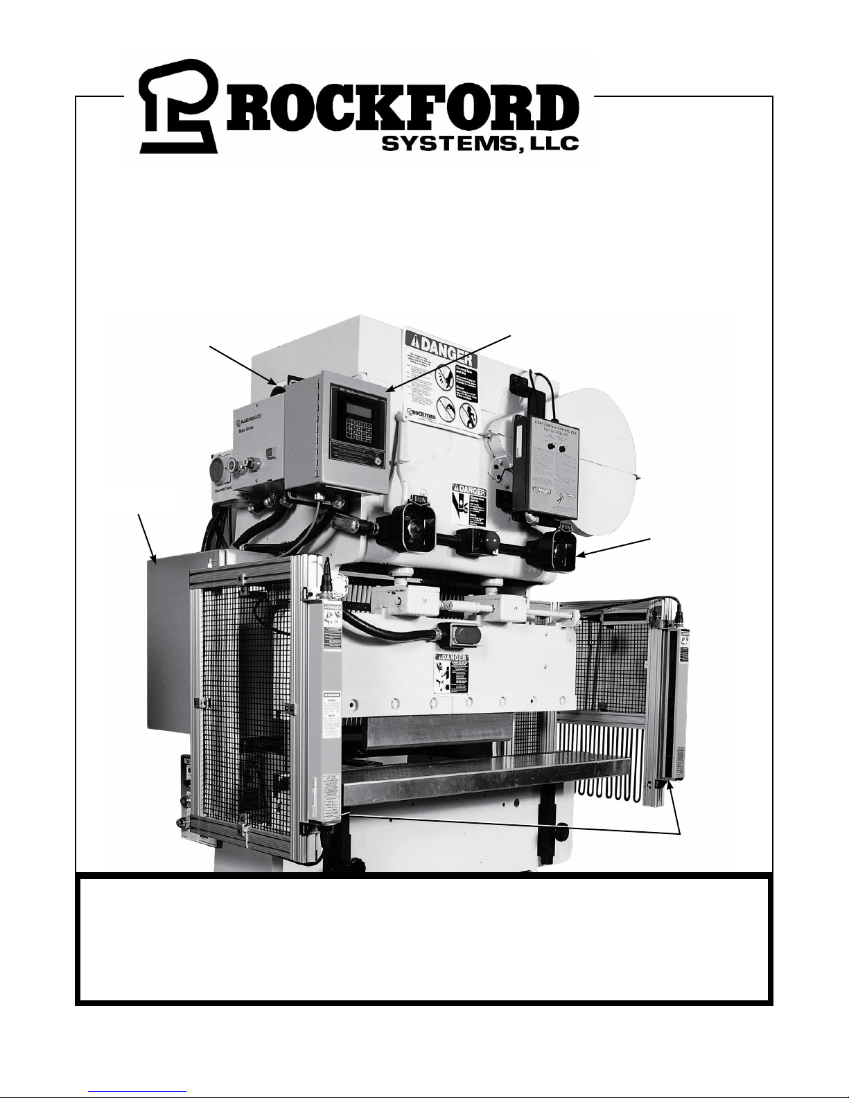
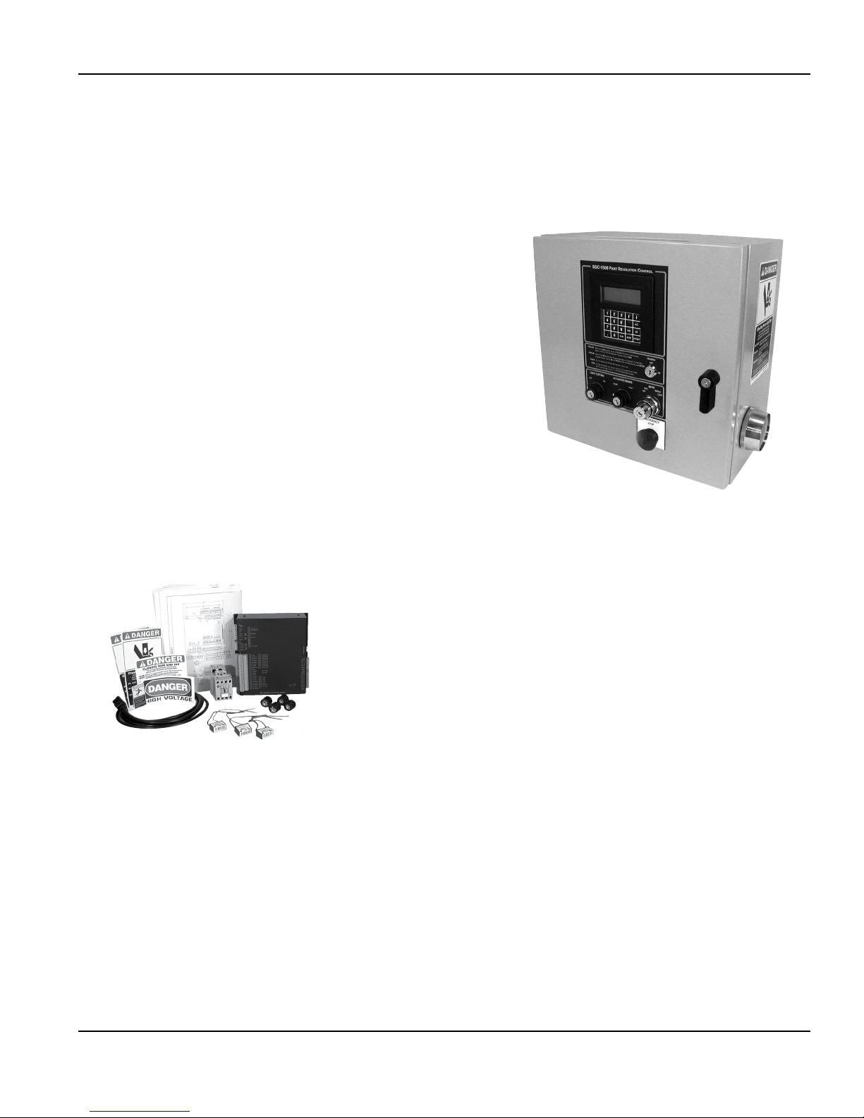
INSTALLATION MANUAL FOR
SSC-1500 GEN II CONTROL SYSTEMS ON
PART-REVOLUTION-CLUTCH PRESS BRAKES
Resolver/Pulser
Plain-Door
Control Box
Assembly
(Not Shown)
Remote Operator
Station
Palm Button
Assembly
IMPORTANT: PLEASE REVIEW THIS ENTIRE PUBLICATION
BEFORE INSTALLING, OPERATING, OR MAINTAINING THE
SOLID-STATE CLUTCH/BRAKE CONTROL SYSTEM.
4620 Hydraulic Road • Rockford, Illinois 61109 • Toll-Free 1-800-922-7533 • Phone (815) 874-7891
Fax (815) 874-6144 • Web Site www.rockfordsystems.com • E-Mail sales@rockfordsystems.com
Light Curtain
Manual No. KSL-277

TABLE OF CONTENTS
SSC-1500 Gen II Part-Revolution Solid-State Control
SECTION 1—IN GENERAL ..................................................................................................................................................................... 3-5
SE CTION 2—INTRODUCTION .............................................................................................................................................................. 6-13
SE CTION 3—INSTALLATION OF COMPONENTS ................................................................................................................................ 14-42
Introduction ........................................................................................................................................................................................ 14
Literature Folder ............................................................................................................................................................................ 14-16
Control Box ................................................................................................................................................................................... 16-24
Resolver/Pulser Assembly .............................................................................................................................................................. 25-26
Sprocket Assembly ............................................................................................................................................................................. 27
Roller Chain ....................................................................................................................................................................................... 28
Monitored Dual-Solenoid Air Valve ..................................................................................................................................................... 28
Filter-Regulator-Lubricator (FRL) Assembly .......................................................................................................................................... 28
Standard and Special Air Cylinders ................................................................................................................................................. 29-30
Air Pressure Switch ............................................................................................................................................................................ 30
Check Valve for Counterbalance System .............................................................................................................................................. 30
Palm Button Assembly ................................................................................................................................................................... 31-35
Foot Switch ................................................................................................................................................................................... 35-36
Supervisory Control Station ................................................................................................................................................................. 36
Multiple-Operator Junction Box ........................................................................................................................................................... 36
Other Components ........................................................................................................................................................................37-40
Other Installation Considerations ....................................................................................................................................................40-42
SECTION 4—PROGRAMMING ........................................................................................................................................................... 43-73
User Inputs ...................................................................................................................................................................................46-49
Brake Monitor ...............................................................................................................................................................................50-52
Counters ....................................................................................................................................................................................... 53-54
System Setup ................................................................................................................................................................................ 55-64
Angle Settings ............................................................................................................................................................................... 65-66
Timed Settings ................................................................................................................................................................................... 67
Optional Modes .................................................................................................................................................................................. 68
PLS Output ........................................................................................................................................................................................ 69
Auxiliary Output ............................................................................................................................................................................. 70-71
Quick Reference Table—Factory Settings and Valid Ranges ............................................................................................................ 72-73
SECTION 5—FATAL AND GENERAL FAULT MESSAGES ....................................................................................................................74-77
SECTION 6—OPERATING CONSIDERATIONS .....................................................................................................................................78-79
SECTION 7—MAINTENANCE AND INSPECTION .................................................................................................................................80-81
SECTION 8—REPLACEMENT PROCEDURES ......................................................................................................................................82-84
SECTION 9—METHODS OF SAFEGUARDING ......................................................................................................................................85-86
SECTION 10—RETURN MATERIALS AUTHORIZATION REQUEST FORM ................................................................................................. 87
SECTION 11—ORDER FORM FOR SIGNS AND LITERATURE ................................................................................................................... 88
Copyright © 2017 by Rockford Systems, LLC All rights reserved. Not to be reproduced in whole or in part without written permission. Litho in U.S.A.
2 Call: 1-800-922-7533
Rockford Systems, LLC
DANGER
Safety Precautions
DANGER indicates an imminently hazardous situation which, if not avoided, will
result in death or serious injury.
This safety alert symbol identifies important safety messages in this manual. When
you see this symbol, be alert to the possibility of personal injury, and carefully read
the message that follows.
SECTION 1—IN GENERAL
SSC-1500 Gen II Part-Revolution Solid-State Control
CAUTION
Efficient and safe machine operation depends on the development, implementation and enforcement of a safety program. This program requires,
among other things, the proper selection of point-of-operation guards and safety devices for each particular job or operation and a thorough safety
training program for all machine personnel. This program should include instruction on the proper operation of the machine, instruction on the
point-of-operation guards and safety devices on the machine, and a regularly scheduled inspection and maintenance program.
Rules and procedures covering each aspect of your safety program should be developed and published both in an operator’s safety manual, as
well as in prominent places throughout the plant and on each machine. Some rules or instructions which must be conveyed to your personnel and
incorporated in to your program include:
DANGER
CAUTION used without the safety alert symbol indicates a potentially hazardous situation
which, if not avoided, may result in property damage.
Never place your hands or any part of your body in this machine.
Never operate this machine without proper eye, face and body protection.
Never operate this machine unless you are fully trained and instructed and unless you have read the instruction manual.
Never operate this machine if it is not working properly—stop operating it and advise your supervisor immediately.
Never use a foot switch to operate this machine unless a point-of-operation guard or device is provided and
properly maintained.
Never operate this machine unless two-hand trip, two-hand control or presence- sensing device is installed at
the proper safety distance. Consult your supervisor if you have any questions regarding the proper safety distance.
Never tamper with, rewire or bypass any control or component on this machine.
A company’s safety program must involve everyone in the company, from top management to operators, since only as a group can any operational
problems be identified and resolved. It is everyone’s responsibility to implement and communicate the information and material contained in catalogs
and instruction manuals to all persons involved in machine operation. If a language barrier or insufficient education would prevent a person from
reading and understanding various literature available, it should be translated, read or interpreted to the person, with assurance that it is understood.
FOR MAINTENANCE AND INSPECTION ALWAYS REFER TO THE OEM’S (ORIGINAL EQUIPMENT
MANUFACTURER’S) MAINTENANCE MANUAL OR OWNER’S MANUAL. If you do not have an owner’s
manual, please contact the original equipment manufacturer.
Rockford Systems, LLC
Call: 1-800-922-7533 3

SECTION 1—IN GENERAL
SSC-1500 Gen II Part-Revolution Solid-State Control
Safety References
OSH ACT AND FEDERAL REGULATIONS
Since the enclosed equipment can never overcome a mechanical
deficiency, defect or malfunction in the machine itself, OSHA
(Occupational Safety and Health Administration) has established certain
safety regulations that the employers (users) must comply with so that
the machines used in their plants, factories or facilities are thoroughly
inspected and are in first-class operating condition before any of the
enclosed equipment is installed.
1. U.S. Government—An Act—Public Law 91-596, 91st Congress,
S. 2193, December 29, 1970:
Duties
SEC. 5. (a) Each employer—
(1) shall furnish to each of his employees employment
and a place of employment which are free from
recognized hazards that are causing or are likely to cause
death or serious physical harm to his employees;
(2) shall comply with occupational safety and health
standards promulgated under this Act.
(b) Each employee shall comply with occupational safety and
health standards and all rules, regulations, and orders issued
pursuant to this Act which are applicable to his own actions
and conduct.
2. OSHA 29 CFR Sections that an employer (user) must comply
with include:
1910.211 Definitions.
1910.212 General requirements for all machines.
1910.217 Mechanical power presses.
1910.219 Mechanical power-transmission apparatus.
3. OSHA 29 CFR 1910.147 The control of hazardous energy
(lockout/tagout).
4. OSHA Publication
“General Industry Safety and Health Regulations Part 1910,” Code
of Federal Regulations, Subpart O
This publication can be obtained by contacting:
Superintendent of Documents
U.S. Government Printing Office
P.O. Box 371954
Pittsburgh, PA 15250-7954
Phone: (202) 512-1800
Fax: (202) 512-2250
www.gpo.gov
ANSI SAFETY STANDARDS FOR MACHINES
The most complete safety standards for machine tools are published
in the ANSI (American National Standards Institute) B11 series. The
following is a list of each ANSI B11 Standard available at the printing
of this publication.
B11.1 Mechanical Power Presses
B11.2 Hydraulic Power Presses
B11.3 Power Press Brakes
B11.4 Shears
B11.5 Iron Workers
B11.6 Manual Turning Machines (Lathes)
B11.7 Cold Headers and Cold Formers
B11.8 Milling, Drilling, and Boring Machines
B11.9 Grinding Machines
B11.10 Metal Sawing Machines
B11.11 Gear and Spline Cutting Machines
B11.12 Roll Forming and Roll Bending Machines
B11.13 Automatic Screw/Bar and Chucking Machines
B11.14 Coil Slitting Machines/Systems
B11.15 Pipe, Tube and Shape Bending Machines
B11.16 Metal Powder Compacting Presses (Withdrawn)
B11.17 Horizontal Hydraulic Extrusion Presses
B11.18 Coil Processing Systems
B11.19 Performance Criteria for Safeguarding
B11.20 Safety Requirements for Manufacturing Systems/Cells
B11.21 Lasers
B11.22 CNC Turning Machines
B11.23 Machining Centers
B11.24 Transfer Machines
B11.TR1 Ergonomics
B11.TR2 Mist Control
B11.TR3 Risk Assessment
R15.06 Robotic Safeguarding
These standards can be purchased by contacting:
American National Standards Institute
25 West 43rd Street
New York, New York 10036
Phone: (212) 642-4900
Fax: (212) 398-0023
www.ansi.org
OR
AMT—The Association for Manufacturing Technology
7901 Westpark Drive
McLean, Virginia 22102
Phone: (703) 893-2900
Toll-Free: 1-800-524-0475
Fax: (703) 893-1151
E-Mail: AMT@amtonline.org
www.amtonline.org
4 Call: 1-800-922-7533
(Continued on next page.)
Rockford Systems, LLC

SECTION 1—IN GENERAL
SSC-1500 Gen II Part-Revolution Solid-State Control
NATIONAL SAFETY COUNCIL SAFETY MANUALS
Other good references for safety on machine tools are the National
Safety Council’s Safety Manuals. These manuals are written by
various committees including the Power Press, Forging and Fabricating
Executive Committee. Copies of the following publications are available
from their library:
• Power Press Safety Manual - 5th Edition
• Safeguarding Concepts Illustrated - 7th Edition
• Forging Safety Manual
These manuals can be obtained by contacting:
National Safety Council
1121 Spring Lake Drive
Itasca, IL 60143-3201
1-800-621-7619 ext. 2199
Fax: (630) 285-0797
www.nsc.org
OTHER SAFETY SOURCES
National Institute of Occupational Safety and Health (NIOSH)
4676 Columbia Parkway
Cincinnati, OH 45226
Toll-Free: 1-800-35-NIOSH (1-800-356-4674)
Phone: (513) 533-8328
Fax: (513) 533-8573
www.cdc.gov/niosh
OTHER SAFETY SOURCES (continued)
Robotic Industries Association (RIA)
900 Victors Way, Suite 140
P.O. Box 3724
Ann Arbor, MI 48106
Phone: (734) 994-6088
Fax: (734) 994-3338
www.roboticsonline.com
NEMA (National Electrical Manufacturers Association)
1300 North 17th Street, Suite 1847
Rosslyn, VA 22209
Phone: (703) 841-3200
Fax: (703) 841-5900
www.nema.org
NFPA (National Fire Protection Association)
1 Batterymarch Park
Quincy, MA 02269-9101
Phone: (617) 770-3000
Fax: (617) 770-0700
www.nfpa.org
For additional safety information and assistance in devising,
implementing or revising your safety program, please contact the
machine manufacturer, your state and local safety councils, insurance
carriers, national trade associations and your state’s occupational
safety and health administration.
Warranty, Disclaimer and Limitation of Liability
WARRANTY
Rockford Systems, LLC warrants that this product will be free from defects in material and workmanship for a period of 12 months from the date of shipment
thereof. ROCKFORD SYSTEMS LLC’S OBLIGATION UNDER THIS WARRANTY IS EXPRESSLY AND EXCLUSIVELY LIMITED to repairing or replacing such products
which are returned to it within the warranty period with shipping charges prepaid and which will be disclosed as defective upon examination by Rockford
Systems, LLC This warranty will not apply to any product which will have been subject to misuse, negligence, accident, restriction and use not in accordance
with Rockford Systems, LLC’s instructions or which will have been altered or repaired by persons other than the authorized agent or employees of Rockford
Systems, LLC Rockford Systems, LLC’s warranties as to any component part is expressly limited to that of the manufacturer of the component part.
DISCLAIMER
The foregoing Warranty is made in lieu of all other warranties, expressed or implied, and
of all other liabilities and obligations on the part of Rockford Systems, LLC, including
any liability for negligence, strict liability, or otherwise, and any implied warranty of
merchantability or fitness for a particular purpose is expressly disclaimed.
Rockford Systems, LLC
Call: 1-800-922-7533 5
LIMITATION OF LIABILITY
Under no circumstances, including any claim of negligence, strict liability, or otherwise,
shall Rockford Systems, LLC be liable for any incidental or consequential damages, or
any loss or damage resulting from a defect in the product of Rockford Systems, LLC
SECTION 2—INTRODUCTION
SYNC SWITCH INPUT
P3 - NETWORK PORT
SSC-1500 Gen II Part-Revolution Solid-State Control
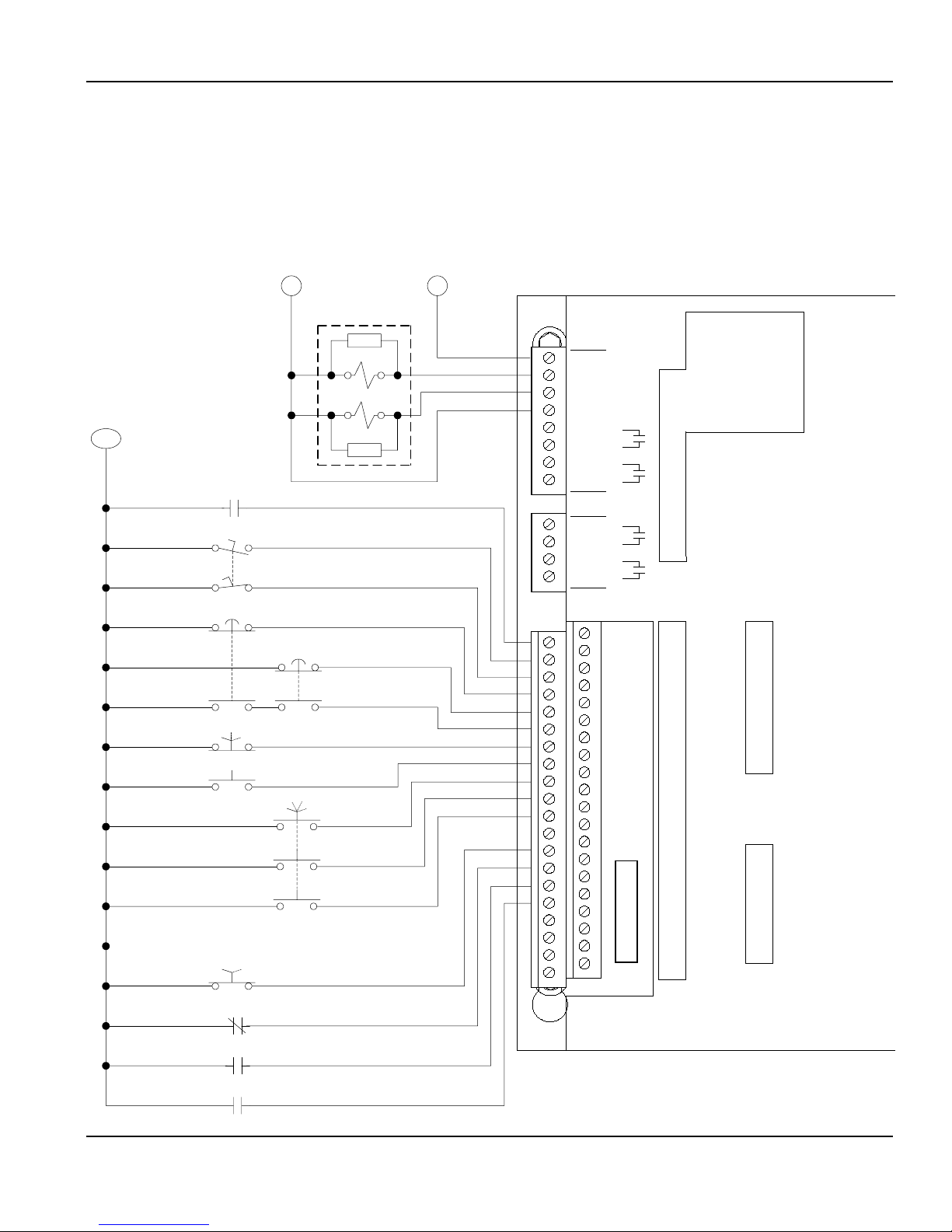
SSC-1500 Gen II Press Brake Control—Connection Diagram
NOTE: This connection diagram is a convenient reference that shows some of the typical connections to the module; it should not be used for
reference during installation. Please refer to the enclosed wiring schematics when installing the control system.
115 V ACX2 - NEUTRAL
L1L2
PNEUMATICALLY CHECKING
DUAL-SOLENOID VALVE*
COM
MASTER CONTROL
RELAY (MCR)
FOOT SWITCH
SUPP
SOLENOID #1
SOLENOID #2
SUPP
*VALVE SHOWN IS FOR SINGLE CLUTCH/BRAKE (ONE VALVE).
SEE WIRING DIAGRAM FOR SPLIT CLUTCH/BRAKE
WIRING DETAIL (TWO VALVES).
RED
RED
RED
WHITE
P6
1 - 115 V AC
2 - SOLENOID #1
3 - SOLENOID #2
4 - X2
5 - PLS #1
6 - PLS #1
7 - SPD CHG
8 - SPD CHG
P7
1 - PLS #2
2 - PLS #2
3 - PLS #3
4 - PLS #3
K1
K2
LEFT PALM BUTTON
RIGHT PALM BUTTON
ACTUATING MEANS
HAND/FOOT
HAND
FOOT
OFF
LIGHT CURTAIN
OFF
ON
LIGHT CURTAIN CONTACT #1
LIGHT CURTAIN CONTACT #2
MODE
INCH SINGLE
SEQUENCE STOP
P8
1 - MCR
2 - FOOT - NO
3 - FOOT - NC
4 - L PB - NC
5 - R PB - NC
6 - L&R PB - NO
7 - HAND
8 - FOOT
9 - INCH
10 - SINGLE
11 - SEQUENCE STOP
12 -
Do not connect more than 24 V DC
to theses inputs.
CAUTION
13 - LC OFF
14 - LC CT #1
15 - LC CT #2
16 - MTR - FWD
17 - SAFEGRD
18 - SAFEGRD
19 -
20 - PROGRAM
21 - USER INPUT #1
22 - USER INPUT #2
23 - USER INPUT #3
24 - USER INPUT #4
25 - USER INPUT #5
26 - USER INPUT #6
27 - USER INPUT #7 (CYCLIC)
28 - USER INPUT #8 (CYCLIC)
29 - 34 - +24 V DC
35 - 40 - COM
+12 V DC
- 12 V DC
+24 V DC
+5 V DC
CPU #1 RUN
CPU #2 RUN
SSC-1500 Gen II DUAL CPU
MAIN MOTOR FORWARD
6 Call: 1-800-922-7533
Rockford Systems, LLC
SECTION 2—INTRODUCTION
SSC-1500 Gen II Part-Revolution Solid-State Control
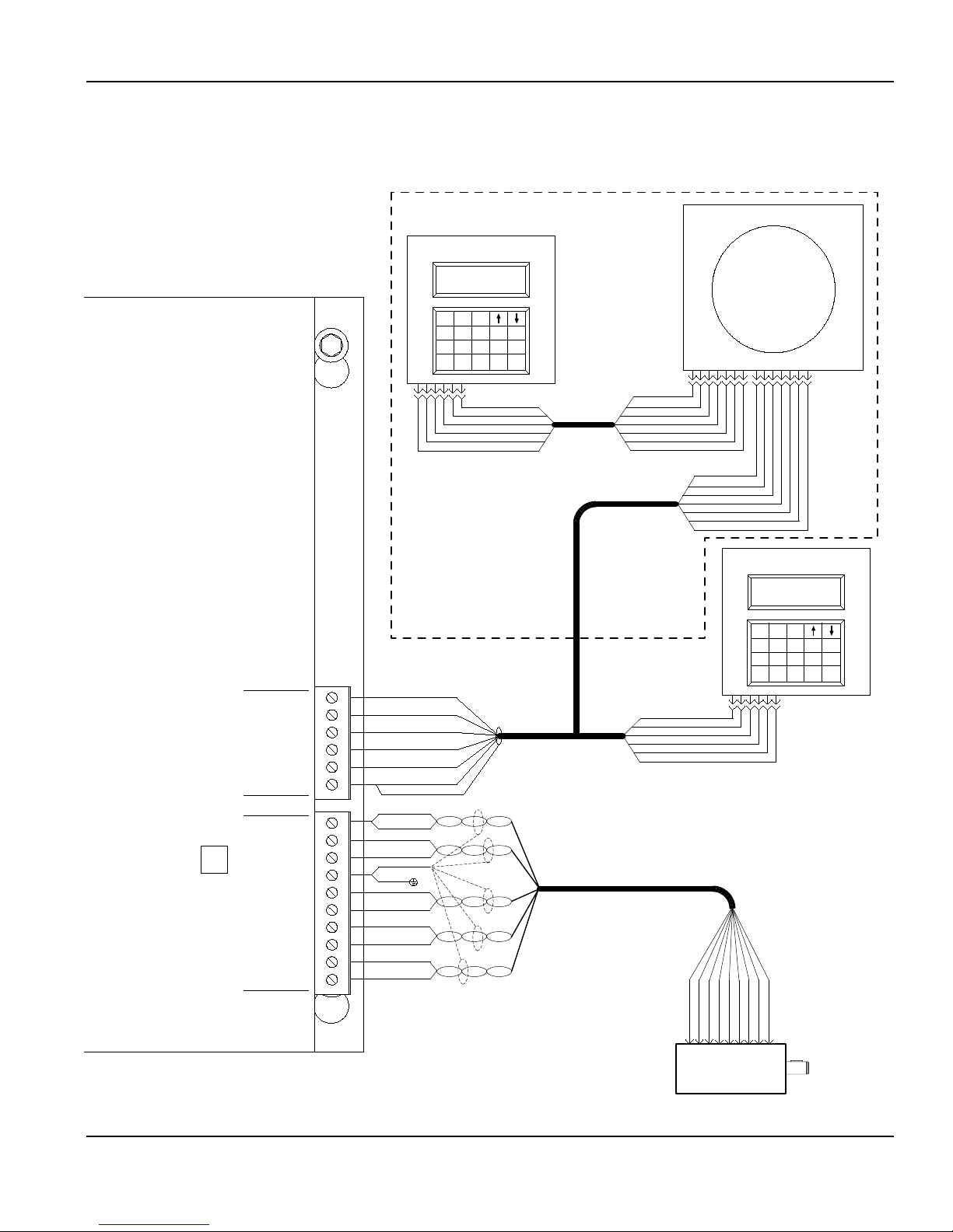
Wiring When Optional Crankshaft Angle Display Is Furnished
KEYPAD/DISPLAY UNIT
FTL-062
CRANKSHAFT ANGLE DISPLAY
FTL-055
P3 - NETWORK PORT
SYNC SWITCH INPUT
CONTROL MODULE
+ TRANSMIT - 6
- TRANSMIT - 5
+ RECEIVE - 4
- RECEIVE - 3
+12 V DC - 2
KEYPAD / DISPLAY
GROUND - 1
COM - 10
+24 V DC - 9
SYNC SWITCH - 8
SHIELD - 7
ROTOR - 6
ROTOR - 5
RESOLVER
BLACK - 4
COSINE - 3
BLACK - 2
Label No. KST-332B
SINE - 1
1
23
45
78 9
.
P1
P4
P5
+ TRANSMIT - BLUE
- TRANSMIT - WHITE
+ RECEIVE - ORANGE
- RECEIVE - BROWN
+12 V DC - RED
GROUND - BLACK
COM - YELLOW
COM - BLACK
+24 V DC - BLUE
SYNC SW - BLACK
SHIELDS (5)
PANEL GROUND
ROTOR - BLACK
ROTOR - RED
COSINE - BLACK
COSINE - WHITE
SINE - BLACK
SINE - GREEN
TWIST THE 5 BARE SILVER SHIELD WIRES TOGETHER AND CONNECT TO
TERMINAL P5-7. CUT OFF THE UNUSED BROWN & BLACK PAIR AND ITS SHIELD.
0
123456
SHIELD
ESC
6
NO
YES
CLR
BKSP
ENTER
150' MAX.
SHIELD - SILVER
+ TRANSMIT - BLUE
- TRANSMIT - WHITE
+RECEIVE - ORANGE
-RECEIVE - BROWN
GROUND - BLACK
+TRANSMIT - ORANGE
RS-422 - 150' MAX.
GROUND - BLACK
+12 V DC - RED
-TRANSMIT - BROWN
+TRANSMIT - ORANGE
- RECEIVE - WHITE
+ RECEIVE - BLUE
CABLE - 7 CONDUCTOR
WITH SHIELD
CONNECT THE BARE SILVER SHIELD WIRE TO TERMINAL P4-1.
(CUT TO LENGTH,
IF REQUIRED, BUT
DO NOT SPLICE)
CUT OFF THE UNUSED
GREEN WIRE.
RS-422 - 150' MAX.
(CUT TO LENGTH, IF REQUIRED,
BUT DO NOT SPLICE)
CUT OFF THE UNUSED GREEN WIRE.
CABLE - 6 TWISTED PAIRS WITH SHIELDS
(CUT TO LENGTH, IF REQUIRED,
BUT DO NOT SPLICE)
P2
7
+12 V DC - RED
+ RECEIVE - BLUE
- RECEIVE - WHITE
-TRANSMIT - BROWN
+ 12 V
DC - RED
GROUND - BLACK
SINE - BLACK
SINE - GREEN
RESOLVER WITH 40' CABL
123456
SHEILD - SILVER
+ TRANSMIT - ORANGE
- TRANSMIT - BROWN
+RECEIVE - BLUE
-RECEIVE - WHITE
+12 V DC -
RED
GROUND - BLACK
P1
BLACK
WHITE
BLACK
- BLACK
ROTOR - RED
ROTOR
COSINE -
COSINE -
SYNC SW -
789
56
CMS-115
P1
7
KEYPAD/DISPLAY UNI
FTL-062
1
23
45
6
78 9
.
CLR
0
123456
BLUE
BLACK
YEL &
+24 V DC -
COM -
1234
P1
E
123456
YES
BKSP
T
ESC
NO
ENTER
Rockford Systems, LLC
Call: 1-800-922-7533 7

SECTION 2—INTRODUCTION
SSC-1500 Gen II Part-Revolution Solid-State Control
General Description of Components in the System
A complete control package for part-revolution-clutch machines includes the following:
1. Literature folder (see pages 14-16) containing installation manuals, Operator Safety Precautions sign, danger sign(s), and electrical control
schematics
2. Control box—a standard (custom or special may include motor controls and/or disconnect switch) with danger and warning signs attached
3. Monitored dual-solenoid air valve
4. Filter-regulator-lubricator (FRL) assembly including connector and mounting bracket
5. Air pressure switch (two required if machine has air counterbalance)
6. Check valve for counterbalance system (if required)
7. Air cylinder (for mechanical-friction-clutch press brakes only)
8. Resolver/pulser assembly, spring base, and 40’ cable
9. Sprocket set to drive resolver/pulser assembly
10. Chain (10 feet with master link)
11. Palm button assembly (Includes two black palm buttons, two palm button guards, one red emergency-stop button, and mounting boxes) If
multiple operator stations are on a machine, more than one assembly is furnished.)
12. Foot switch (optional)—If multiple operator stations are on a machine, more than one foot switch is furnished.
13. Supervisory control station (Required when multiple operator stations are used on the machine; one station is required for each operator.)
14. Multiple-operator junction box (When multiple operator stations are required, this junction box is furnished separately for wiring up to four
operator stations.)
15. Other required components and safeguarding that may be necessary for the machine (See packing list for details.)
Individual packages may vary in contents. However, a packing list is always enclosed showing exactly what material was shipped on this order.
Please check the components actually received against this packing list immediately. In most cases, this control package system includes two-hand
control which can be used as a point-of-operation safeguarding device provided the palm buttons are mounted correctly and at the proper safety
distance (see formula on page 32 of this manual). If the optional foot switch is provided, a safeguard must always be used. Examples of safeguards
include barrier guards, presence-sensing devices, pullbacks, restraints, gates, or two-hand control. The hands or any other part of the body of an
operator, maintenance person, setup person, etc., must never be put into the point-of-operation hazard for any reason, at any time.
This control can neither cure nor overcome a malfunctioning machine. It cannot compensate for or prevent
a mechanical defect or failure of a machine part. This control cannot prevent a repeat or unintended stroke
(cycle) resulting from a mechanical malfunction, defect or failure of the machine itself.
Preliminary Steps Before Installation
Before proceeding with the installation of the enclosed equipment, you should undertake the following preliminary steps.
1. Read and make sure you understand this entire installation manual.
2. Refer to the front cover, other line drawings and photos, then make a sketch of your installation to plan the location of the enclosed
equipment on the machine.
3. This may be an opportunity to strip down the entire machine by removing all components, piping, wire, etc. Clean, paint and check the
entire mechanical condition of the machine, including the clutch and brake, for proper adjustment and required replacement parts before
proceeding with the installation of the furnished equipment.
8 Call: 1-800-922-7533
(Continued on next page.)
Rockford Systems, LLC

SECTION 2—INTRODUCTION
SSC-1500 Gen II Part-Revolution Solid-State Control
Preliminary Steps Before Installation (continued)
4. Please make sure the machine is in first-class condition. Before starting any installation, it is essential that the machine is thoroughly
inspected. Be sure all mechanical components and all collateral equipment are in first-class operating condition. Your inspection should
be done according to the machine manufacturer’s installation and maintenance instruction manual. Special attention must be given to the
machine clutch and brake. The clutch and brake must be maintained in an operating condition which is within the specifications set by the
machine manufacturer. If you have any doubts or questions concerning the condition of the machine, contact the machine manufacturer for
assistance. Repair or replace all parts not operating properly before proceeding.
Inspection and maintenance programs must be established and implemented to keep machines in first-class condition.
Safety programs must include thorough inspections of each machine on a weekly basis and records kept of these
inspections. Any part of the machine that is worn, damaged or is not operating properly must be replaced immediately or
repaired before the machine is used.
5. Verify that the machine is in first-class condition and operating properly; shut off all power to the machine. Padlock all electrical and
pneumatic energy in the off position and do not actuate the machine again until the installation of all package components has been
completed. Lockout/tagout energy isolation procedures must always be practiced and enforced.
6. If the machine has a mechanical-friction clutch, an air cylinder is required to engage and disengage the clutch. Install the air cylinder in the
most logical place to actuate the clutch. Please see the enclosed Installation Manual No. KSL-096 if an air cylinder was ordered. Note: On
machines equipped with air-operated friction clutches, an air cylinder is not required.
Safeguard Interlocks and Other Types of Interlocks
SAFEGUARD INTERLOCKS
The machine will not operate or must not be operated until you either: (1) electrically interlock or (2) mechanically safeguard the machine’s point
of operation with a guard or device.
When an electrically interlocked method of safeguarding the point of operation is chosen, connect the interlock to the safeguard interlock terminals
(P8-17 and P8-18) in the control box, and as shown on the control wiring schematic (wire numbers 86 and 87). If a light curtain(s) is used as the
point-of-operation safeguard, it does not need to be interlocked in to P8-17 and P8-18 safeguard interlock terminals. Refer to the control wiring
schematic for proper terminal connection of the light curtain.
Point-of-operation electrically interlocked safeguards, when opened, prevent or stop normal machine operation during operator cycling modes.
Examples of these types of interlocks are barrier guard interlocks and gate device interlocks.
When a mechanical guard or device (nonelectrically interlocked) is chosen, the safeguard interlock terminals (P8-17 and P8-18) are not used. In
order for the machine to operate with the use of a mechanical guard or device, the safeguard interlock terminals must be connected. Please see
the wiring schematic.
The mechanical guard or device must be properly installed, used and maintained and must always prevent all personnel
from bodily injury.
If the mechanical guard or device is not used, is removed, or is defeated, an electrically interlocked method of safeguarding
must be used and connected to the safeguard interlock terminals (P8-17 and P8-18).
Never operate this machine without point-of-operation safeguarding.
Rockford Systems, LLC
Call: 1-800-922-7533 9

SECTION 2—INTRODUCTION
SSC-1500 Gen II Part-Revolution Solid-State Control
OTHER ELECTRICAL INTERLOCKS
There are basically two types of electrical interlocks as applied to machine control circuitry:
• Interlocks for the purpose of personnel protection, as explained on page 9.
• Interlocks intended for the purpose of protecting the machine and its control components.
There are other locations for interlocks that, when opened, prevent all machine functions. Examples of these types of interlocks are safety block
electrical cut-off systems, lubricating systems, die protection equipment, and tonnage monitoring systems.
Be sure to connect the various electrical interlocks to the proper terminals, in the control box, according to the machine wiring schematics. If your
schematics do not include these electrical interlocks, please send this information to the factory and they can be added to your drawings. There is an
additional charge for this service.
General Features of the SSC-1500 Gen II Control
• Redundant/Cross-Checking Microprocessors
• Redundant Microprocessor Logic Power Supplies
• Triple-Redundant Solid-State Solenoid Relays
• 4-Line x 20-Character LCD (Liquid Crystal Display) With 20-Key Keypad
• Absolute Resolver/Pulser With Sync Sensor for Timing and Motion Detection
• Wide Range of Input Power Supply—85 to 135 V AC
• Time-Based Brake Monitor With Programmable Warning and Fault Setpoints
• 6 User-Programmable 24-V DC Static Diagnostic or Die Protection Inputs
• 2 User-Programmable 24-V DC Cyclic Die Protection Inputs
• 7-Digit Total Counter, 7-Digit Batch Counter With Preset, and 7-Digit Stroke Counter With Preset
• Light Curtain(s) Interface With Off/On Selector Switch
• 4 PLS (Programmable Limit Switch) Outputs—2 On/Off Angles, or 1 Timed Off, or 1 Counted Output (or 3 PLS Outputs and 1 Auxiliary Output
With 1 Contact)
• Fo r Two-Speed Operation: 3 PLS (Programmable Limit Switch) Outputs—2 On/Off Angles, or 1 Timed Off, or 1 Counted Output (or 2 PLS
Outputs and 1 Auxiliary Output With 1 Contact)
• In formation Displayed When the Machine Is in Operation—Angle, Speed,
Batch Counter, Stroke Counter, Mode of Operation, and Stop Time
• Display of Text in English or Spanish
MODES OF OPERATION
• Off
• Two-Hand Inch (Regular, Timed, or Top-Stop)
• Two-Hand Single Stroke
• Foot Single Stroke
• Sequence Stop (Hand/Hand—Hand/Foot—Foot/Foot)
• High/Low Automatic Speed Change (for Two-Speed Only)
10 Call: 1-800-922-7533
Rockford Systems, LLC

SECTION 2—INTRODUCTION
SSC-1500 Gen II Part-Revolution Solid-State Control
Overview of Motion and Settings
The redundant inputs are used by both processors to control the operation of the press brake. When the actuating means are depressed, and
the primary safeguard interlock conditions are met, the processors turn on their appropriate relays (SSR1 and SSR2). The dual-solenoid valve is
energized sending air to the air cylinder or clutch and brake. The crankshaft is engaged to the flywheel drive and the brake is released allowing the
ram to move. Within the motion reference time window, the microprocessors must see a voltage signal from the DC tachometer in the resolver/
pulser assembly that represents motion or a motion fault is generated. If the actuating means are released prior to the auto up (holding) angle, the
slide movement will stop. The stroke can be finished by depressing the actuating means again.
For brake monitoring, the control starts a timer when the relays and solenoids are de-energized. This timer stops when the motion from the
tachometer in the resolver/pulser has stopped. The stop-time value is then compared to the brake stop-time setpoint. If the stop time exceeds
this setting, a brake fault message is displayed. The reason for the increased stop time should be investigated and corrected before operating the
machine again. (See pages 50-52 for programming the brake monitor.)
Sequence of Operation
This sequence of operation applies to all standard modes provided with the SSC-1500 Gen II press brake control.
OFF
The press brake is inoperable in this mode of operation. The OFF position cannot be used solely as the lockout/tagout means. To use any of the
following modes of operation, turn the mode selector switch from OFF to the appropriate position.
Two-Hand Inch is a mode of operation in which the ram travels as long as the operator(s) maintains actuation of the palm buttons. Each time the
buttons are released, the ram will stop.
If Timed Inch is turned on, the clutch will engage and the ram will move only for a set amount of time programmed in to the control, even if the
palm buttons are held depressed. See page 67 of this installation manual for Timed Inch programming information.
To use Two-Hand Inch, the mode selector switch must be set to INCH, and the actuating means selector switch must be set to HAND.
Top-Stop Inch is similar to normal Inch. If Top-Stop Inch is turned on, the slide will stop at top every cycle, even if the palm buttons are held
depressed. See page 68 of this installation manual for Top-Stop Inch programming.
The Inch mode of operation is used for die setup, tool setup, and maintenance only. It is not intended for use during
production operations.
TWO-HAND SINGLE STROKE
Two-Hand Single Stroke is a mode of operation in which the slide makes one complete stroke or cycle upon actuation of the palm buttons. The
palm buttons must be held depressed until the programmed automatic up (holding) angle is reached. If they are released before this angle is reached,
the slide will stop and the buttons will need to be released and then reactuated. The automatic up (holding) angle should be programmed so that the
palm buttons are held depressed during the entire die-closing portion of the stroke. Once the slide passes the automatic up (holding) angle, the
palm buttons can be released and the slide will automatically return to the top.
To use Two-Hand Single Stroke, the mode selector switch must be set to SINGLE, and the actuating means selector switch must be set to HAND.
Rockford Systems, LLC
Call: 1-800-922-7533 11
(Continued on next page.)

SECTION 2—INTRODUCTION
SSC-1500 Gen II Part-Revolution Solid-State Control
FOOT SINGLE STROKE
Foot Single Stroke is a mode of operation in which the ram makes one complete stroke or cycle upon actuation of the foot switch. The foot switch
must be held depressed until the programmed automatic up (holding) angle is reached. If it is released before this angle is reached, the ram will
stop and it will need to be released and then reactuated. Once the ram passes the automatic up (holding) angle, the foot switch can be released
and the ram will automatically return to the top.
To use Foot Single Stroke, the mode selector switch must be set to SINGLE, and the actuating means selector switch must be set to FOOT.
A point-of-operation safeguard must be used when using this mode of operation.
HAND/HAND SEQUENCE STOP
Hand/Hand Sequence Stop is a mode of operation in which the palm buttons are held depressed until the slide automatically stops at the
programmed sequence stop point (usually 1⁄4” above the workpiece). If the palm buttons are released during this portion of the stroke, the slide will
stop and the buttons will need to be released and then reactuated. Once the sequence stop point is reached, the palm buttons must be released,
and the operator can position the workpiece or make sure it is in place. The palm buttons must then be reactuated to finish the stroke. After the
sequence stop point, the slide can either be inched through the bottom of the stroke, or it can automatically return to the top, depending on where
the programmed automatic up (holding) angle is set.
To use Hand/Hand Sequence Stop, the mode selector switch must be set to SEQ STOP, and the actuating means selector switch must be set
to HAND.
HAND/FOOT SEQUENCE STOP
Hand/Foot Sequence Stop is a mode of operation in which the palm buttons are held depressed until the slide automatically stops at the
programmed sequence stop point (usually 1⁄4” above the workpiece). If the palm buttons are released during this portion of the stroke, the slide will
stop and the buttons will need to be released and then reactuated. Once the sequence stop point is reached, the palm buttons must be released,
and the operator can position the workpiece or support it in place. The foot switch must then be actuated to finish the stroke. After the sequence
stop point, the slide can either be inched through the bottom of the stroke, or it can automatically return to the top, depending on where the
programmed automatic up (holding) angle is set.
To use Hand/Foot Sequence Stop, the mode selector switch must be set to SEQ STOP, and the actuating means selector switch must be set
to HAND/FOOT.
FOOT/FOOT SEQUENCE STOP
Foot/Foot Sequence Stop is a mode of operation in which the foot switch is held depressed until the slide automatically stops at the programmed
sequence stop point (usually 1⁄4” above the workpiece). If the foot switch is released during this portion of the stroke, the slide will stop and the
foot switch will need to be released and then reactuated. Once the sequence stop point is reached, the foot switch must be released, and the
operator can position the workpiece or support it in place. The foot switch must then be reactuated to finish the stroke. After the sequence stop
point, the slide can either be inched through the bottom of the stroke, or it can automatically return to the top, depending on where the programmed
automatic up (holding) angle is set.
To use Foot/Foot Sequence Stop, the mode selector switch must be set to SEQ STOP, and the actuating means selector switch must be set to FOOT.
A point-of-operation safeguard must be used when using this mode of operation.
12 Call: 1-800-922-7533
(Continued on next page.)
Rockford Systems, LLC

SECTION 2—INTRODUCTION
SSC-1500 Gen II Part-Revolution Solid-State Control
NOTE: The following feature can only be used with two-speed air-clutch press brakes.
HIGH/LOW SPEED CHANGE
High/Low Speed Change is a feature in which the slide switches from high to low speed at the programmed speed change on angle (usually
1
⁄4” above the workpiece). This reduces whip-up action and allows more control when forming the part. The slide continues in low speed until the
programmed speed change off angle is reached (usually at the bottom of the stroke or slightly after), and then it returns to the top of the stroke in
high speed.
To use High/Low Speed Change, the mode selector switch can be in any position, and the speed selector switch must be set to HIGH/LOW.
OPTIONAL MODES
Top-Stop Inch and Inch With Fault are optional modes of operation also provided with the SSC-1500 Gen II press brake control. These modes
of operation are accessed through the optional modes program screen. See page 68 of this installation manual for programming information.
A point-of-operation safeguard must be used when using any of these modes of operation.
Rockford Systems, LLC
Call: 1-800-922-7533 13
SECTION 3—INSTALLATION OF COMPONENTS
SSC-1500 Gen II Part-Revolution Solid-State Control
Introduction
The following additional materials are required to install the equipment in this shipment.
1. Wire: Size and type will depend on local ordinances or plant practices. We recommend stranded machine tool wire with appropriate colorcoding. Never use solid wire—the vibration caused by these machines precludes the successful use of solid wire for these installations.
2. Numbered wire markers: Made of suitable material to resist oil, grease, etc., and remain firmly attached to the wire.
3. Conduit: Rigid, liquid-tight flexible, or any other suitable tubular connecting means which complies with local ordinances and provides
adequate mechanical protection for the wires. Most of the electrical products supplied have an oil-tight construction.
4. Miscellaneous wiring components such as electrical tape, wire connectors, and terminals, as required.
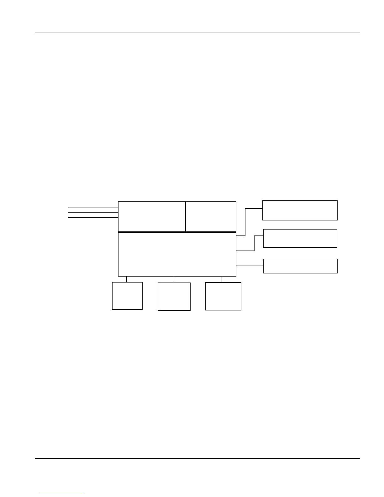
ILLUSTRATION OF ELECTRICAL SYSTEM ON PART-REVOLUTION-CLUTCH POWER PRESS BRAKE
Primary
Voltage
115 V
208 V
230 V
460 V
575 V
DISCONNECT
Safety
Block
Interlock
(If furnished)
SWITCH
PRESS BRAKE
CONTROL
Foot Switch
(If furnished)
MOTOR
STARTER
Palm Button
Assembly
(If furnished)
Resolver/Pulser
Assembly
Dual-Solenoid
Air Valve
(If furnished)
Air Pressure Switch
(If furnished)
LITERATURE FOLDER
Included with every shipment is a literature folder. This includes installation manuals, Operator Safety Precautions sign (Part No. KSC-000),
danger signs, and electrical schematics. These publications must be available and fully understood by all appropriate personnel, before any retrofit
installation begins. Please notify Rockford Systems immediately if there are any questions about the components received.
14 Call: 1-800-922-7533
(Continued on next page.)
Rockford Systems, LLC
SECTION 3—INSTALLATION OF COMPONENTS
SSC-1500 Gen II Part-Revolution Solid-State Control
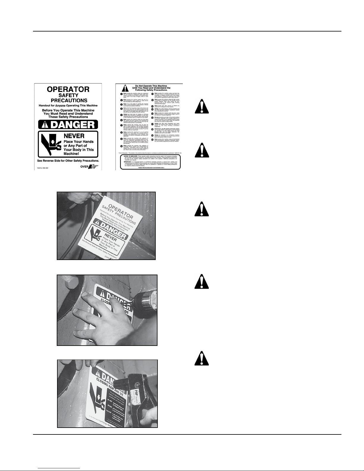
OPERATOR SAFETY PRECAUTIONS SIGN
Photo 3.1 - Part No. KSC-000 Operator Safety Precautions Sign
Front
Photo 3.2
Back
Attachment of Precautions Sign
1. Locate the Operator Safety Precautions sign.
2. Attach the sign to the machine with a nylon tie through the hole
provided. See Photo 3.2.
Attach it to the machine where it is readily
accessible and visible to the operator. Additional
copies of these precautions are available. Please
call, write, fax, e-mail or use the order form found
on a later page in this manual.
When a language barrier or insufficient education
prevents a person from reading or understanding
the contents of this sign, you should either
translate this information or have it read or
interpreted to the person. Make sure the person
understands the information. To order this sign
in Spanish, use Part No. KSC-000S; in French, use
Part No. KSC-000F.
These precautions must be reviewed daily.
Photo 3.3
Photo 3.4
DANGER SIGNS
1. Locate the furnished danger signs.
2. Determine the mounting location for the danger signs on the
machine.
They must be permanently mounted in a
prominent location on the machine where they
are readily accessible and visible to the operator,
setup person, or other personnel who work on or
around this machine.
3. Drill a hole(s) in the sign and the machine at the mounting
location. See Photo 3.3.
4. Attach the signs to the machine with screws or rivets. See
Photo 3.4.
Never operate this machine unless the danger
signs are in place. Also make sure the signs
are read and understood before operating the
machine.
Rockford Systems, LLC
Call: 1-800-922-7533 15
SECTION 3—INSTALLATION OF COMPONENTS
SSC-1500 Gen II Part-Revolution Solid-State Control
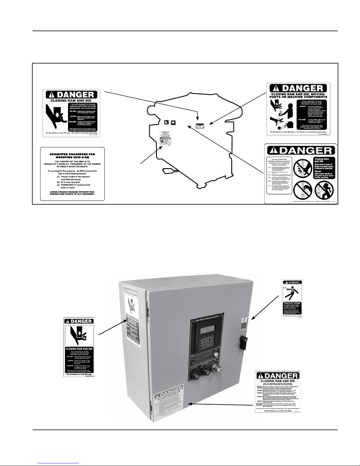
Figure 3.1 - Illustration of the Placement of the Operator Safety Precautions Sign and Danger Signs
Part No. KSC-054 Danger Sign—Standard
Part No. KSC-054S—Spanish
Part No. KSC-054F—French
Front Side
Part No. KSC-000
Operator Safety
Precautions Sign
Reverse Side
Control Box
DANGER AND WARNING LABELS PROVIDED
Part No. KSC-055 Danger Sign (Foot)
Part No. KSC-055S—Spanish
Part No. KSC-055F—French
Front Side
Part No. KSC-060
The illustrated danger and warning labels are affixed to all control boxes provided. All personnel operating or working around the machine, where
this control box is installed, must be required to read, understand and adhere to all dangers and warnings. If any of these labels become destroyed
or unreadable, they MUST be replaced. Contact the factory immediately for replacement labels and do not operate the equipment until danger and
warning labels are all in place.
Photo 3.5
SSC-1500 Gen II Standard
Control Box Outside View
Label No.
KST-134
Label No.
KST-152
Label No.
KST-135
16 Call: 1-800-922-7533
Rockford Systems, LLC
SECTION 3—INSTALLATION OF COMPONENTS
SSC-1500 Gen II Part-Revolution Solid-State Control
Control Box (continued)
The SSC-1500 Gen II is an economic, full-featured, dual-microprocessor-based control for part-revolution-clutch mechanical power press
brakes. This control system is designed to comply with OSHA 29 CFR 1910.212 and ANSI B11.3. It is a replacement for existing relay-based
control systems, found in users’ plants, or can be furnished for new or rebuilt press brakes.
This control can be supplied in a custom box with a motor starter(s) and a disconnect, or as a standard control to interface with existing press
motor controls. Enclosure systems for the control include a standard 20” x 20” x 8” box with the keypad/display mounted on the door of the
enclosure. A plain-door enclosure with the keypad/display mounted in a remote operator station may have been furnished.
When the control box is wired to an existing main motor starter, the starter must have a 120-V coil and in most cases, an auxiliary contact. If
the starter does not have these components and they are not readily available, please contact Rockford Systems for a replacement magnetic
motor starter.
The system uses redundant inputs from devices such as palm buttons, foot switches, and light curtain(s). The system output to the dual-solenoid
air valve is provided by one safety relay with force-guided contacts and two solid-state relays. These output relays are independently controlled
and cross-checked by the microprocessors. This allows control-reliable operation of the outputs in the event of a single control component
failure. Each microprocessor also has its own logic power supply. This decreases the possibility of simultaneous control failure because of a fault
within the power supply system. All the inputs are optically isolated for electrical noise immunity. Timing and motion detection of the crankshaft
is provided by the resolver/pulser assembly. The operator provides setup information through the use of the keypad/display and messages are
shown on the 4-line x 20-character LCD.
This solid-state control operates at a low voltage. Any component such as the dual valve or anything the control will operate (i.e., relay, solenoids)
that is at a higher voltage (115 V) must be suppressed. Three (3) suppressors are furnished with all control boxes. Make sure they are installed
on the solenoid contacts to filter out electrical noise that could affect the operation of the control.
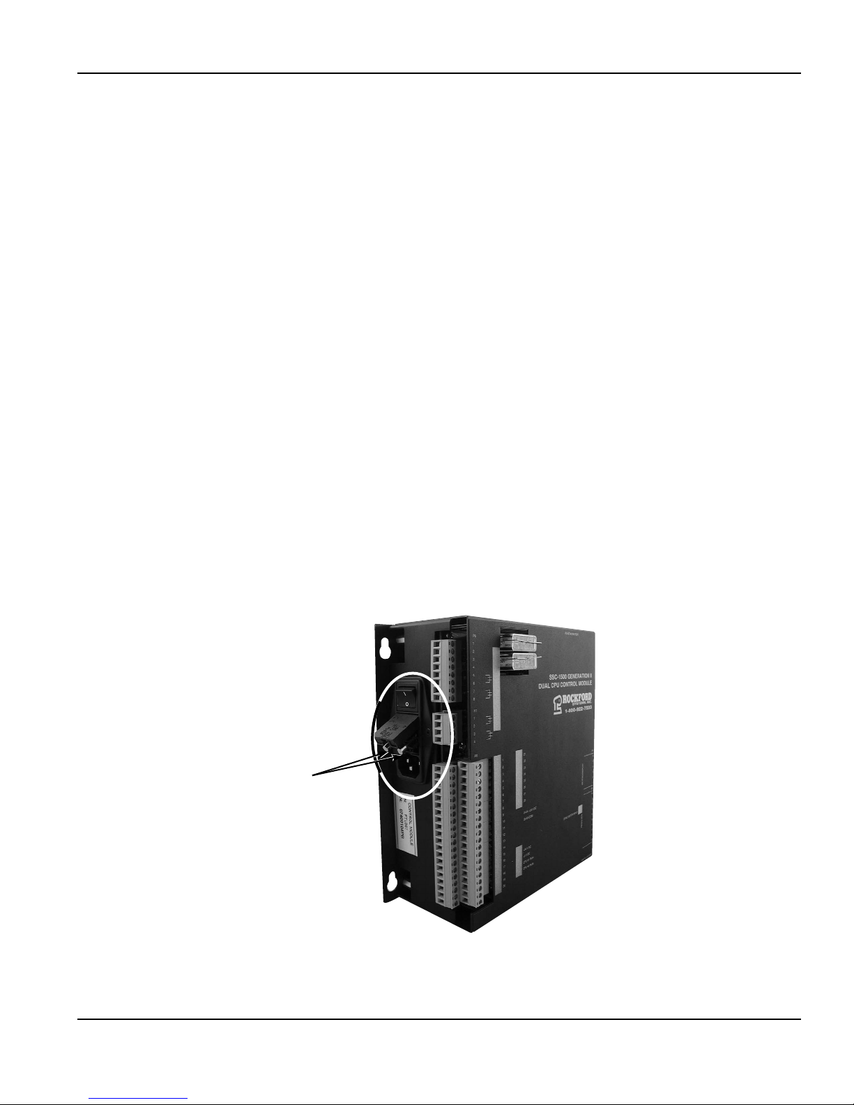
Two extra fuses are also furnished with all control boxes. Use the corresponding replacement fuse if the original fuse should blow on the printed
circuit board (fuses F1 through F6—see page 21), or to replace a blown fuse inside the off/on switch on the side of the control module
(see Photo 3.7).
Fuses MPF1
& MPF2
Rockford Systems, LLC
Call: 1-800-922-7533 17
Photo 3.7
Fuse location in the off/on switch on the
control module.

SECTION 3—INSTALLATION OF COMPONENTS
SSC-1500 Gen II Part-Revolution Solid-State Control
STANDARD CONTROL BOX
The standard control box (20” x 20” x 8”) is furnished with the keypad/
display, program off/on selector switch, and other selector switches on the
front of the enclosure door. This NEMA 12 enclosure contains the control
module assembly, master control relay, primary multi-tap transformer, and
terminal strips. A standard box with a plain door is also available for use with
a remote operator station.
Photo 3.9
Inside View of Standard Control Box
Master Control
Relay
Photo 3.8
Standard Control Box
Multi-Tap
Transformer
CUSTOM CONTROL BOX
A custom control box contains the standard control module and
components described above plus the following:
• main power disconnect switch
• main drive motor starter
• ram-adjust motor starter (if furnished)
This NEMA 12 enclosure will vary in size based on the size
of the disconnect switch and motor starter components. The
enclosure contains the disconnect switch, main motor starter, ramadjust motor starter (if furnished), clutch/brake control module,
master control relay, primary multi-tap transformer, and terminal
strips. The keypad/display, selector switches, motor controls, and
disconnect switch handle may have been furnished on the door of
the enclosure, or furnished as a plain-door enclosure for use with
a remoter operator station.
SSC-1500 Gen II Control
Module Assembly
Photo 3.10
Plain-Door Custom Control Box with Remote Operator Station
18 Call: 1-800-922-7533
Rockford Systems, LLC
SECTION 3—INSTALLATION OF COMPONENTS
SSC-1500 Gen II Part-Revolution Solid-State Control
REMOTE OPERATOR-STYLE CONTROL BOXES
Remote operator-style control boxes include the same features and modes of operation as the standard control box described on page 18. However,
they do not have a control transformer. These controls are for applications where the machine’s existing magnetic motor starter, fused disconnect
switch, and control transformer meet the safety requirements and can be reused. If the existing control transformer cannot be reused or a new
control transformer is required, contact the factory.
The three remote operator-style control boxes available have the keypad/display
and all operators on the door of the 16” x 16” x 8” enclosure. The remote
operator-style control boxes available are:
Style X— Standard SSC-1500 Gen II control box without the control
transformer
Style Y— Standard SSC-1500 Gen II control box without the control
transformer, but with an e-stop button in the enclosure
Style Z— Standard SSC-1500 Gen II control box without the control
transformer, but with an e-stop button, and two (2) guarded
run/inch buttons on the sides of the enclosure
Photo 3.11
Style Z Remote Operator Control Box
CONTROL MODULE KIT*
When a control module kit is furnished, it is supplied without the control enclosure, panel,
control transformer, control fuse, terminal strips, wire duct, and wiring. This control module kit
includes the control module, master control relay, shock mounts, fasteners, suppressors, extra
fuses, ferrules, danger labels, and electrical prints. The minimum area required to install this kit
on an existing control panel is 14” x 12” x 6”. The electrical prints supplied with this kit show
typical wiring and all dimensions.
Photo 3.12
KEYPAD/DISPLAY KIT*
PART NO. LLD-1519
When a keypad/display kit is furnished for use with any of the control boxes or control module kit, it includes the keypad/display, a screen label, a
program off/on selector switch, a light curtain off/on selector switch, an actuating means selector switch, a mode selector switch, and 25’ of cable.
Additional push buttons and nameplates for motor starters, etc., may have been furnished depending on the features required. The area needed to
mount the keypad/display kit is 10” x 10
1
⁄2” x 31⁄2”.
* A certified electrician is required for the installation of a control module kit and keypad/display kit. If you do not have access to a certified electrician,
please contact Rockford Systems at 1-800-922-7533, and we will propose the cost of having our installation team provide the installation.
Rockford Systems, LLC
Call: 1-800-922-7533 19
SECTION 3—INSTALLATION OF COMPONENTS
SSC-1500 Gen II Part-Revolution Solid-State Control
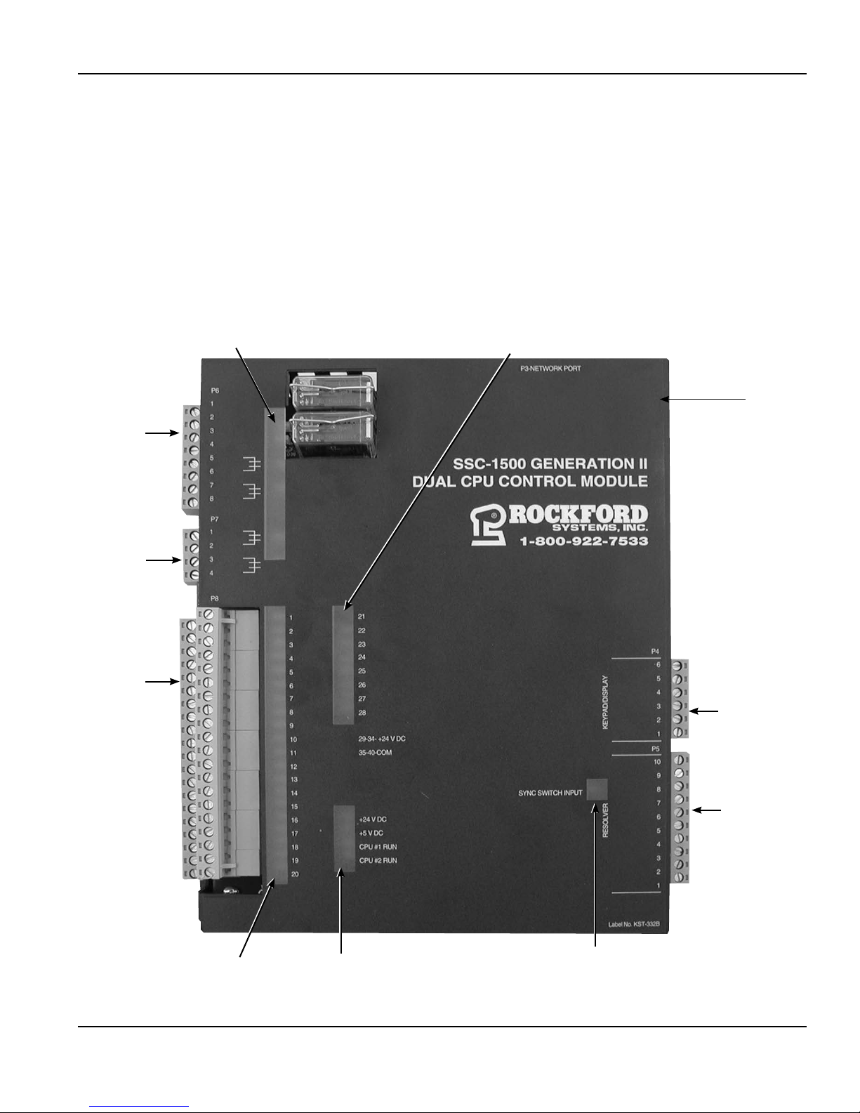
CONTROL MODULE ASSEMBLY
The solid-state control module assembly below, Part No. FTL-067, measures 81⁄4” W x 83⁄4” H x 33⁄4” D. It is mounted to the panel with four shock/
vibration mounts and four 1⁄4-20 x 1⁄2” Allen-head bolts. The module case has four keyhole mounting slots that allow for easy removal, without taking
off the Allen-head mounting bolts.
Red and green LEDs allow for visual indication of control operation and the status of inputs and outputs. There are two green CPU (central processing
unit) run indicator status lights. All LED names are indicated on the cover of the module next to each LED. See photo 3.14.
Photo 3.14
Top View of Control Module With Cover
Terminal Strip P6
Terminal Strip P7
Terminal Strip P8
Output LEDs
User Input LEDs
Top Cover
Terminal Strip P4
Input LEDs
20 Call: 1-800-922-7533
CPU LEDs
Terminal Strip P5
Sync Switch Input LED
(Continued on next page.)
Rockford Systems, LLC
SECTION 3—INSTALLATION OF COMPONENTS
SSC-1500 Gen II Part-Revolution Solid-State Control
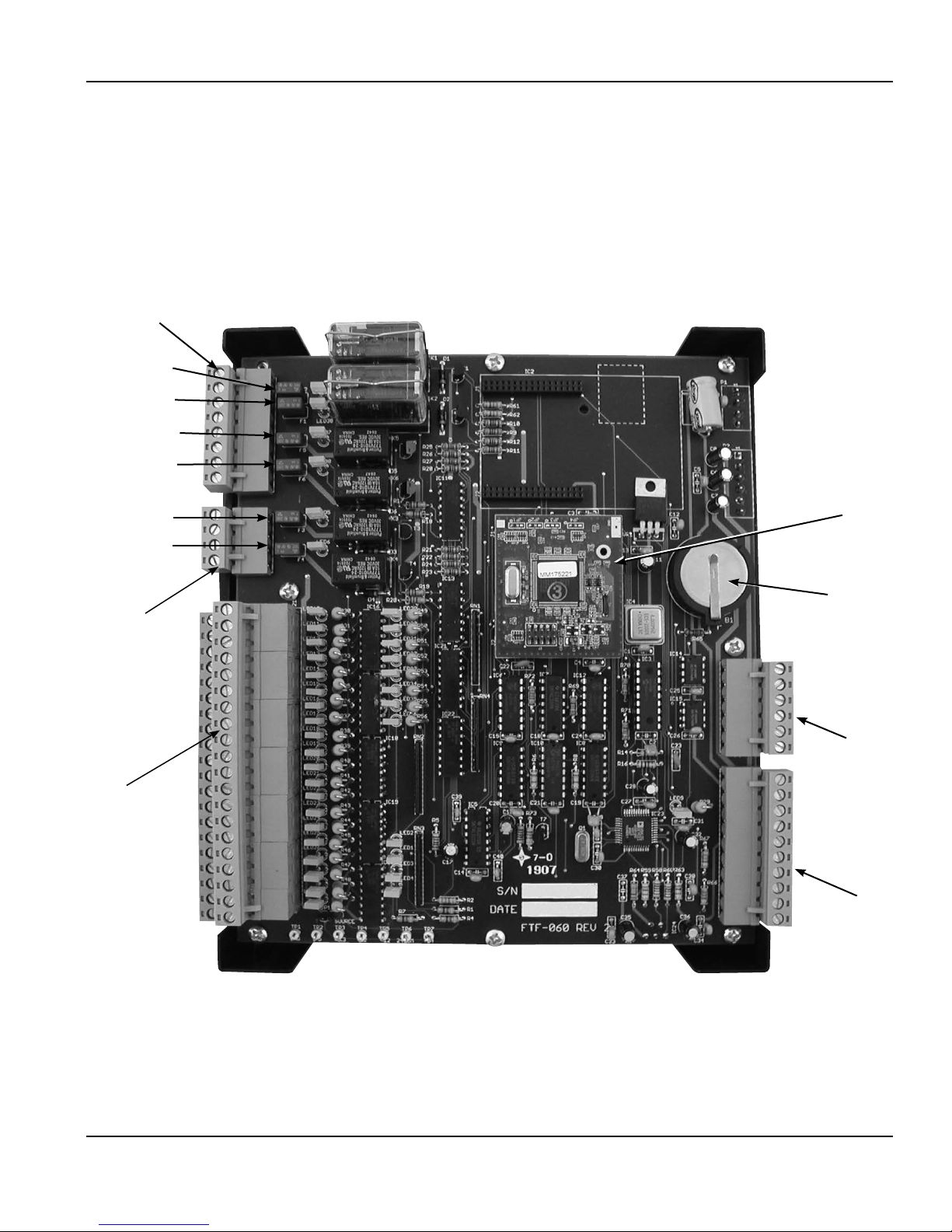
CONTROL MODULE ASSEMBLY (continued)
If necessary, the cover of the module can be taken off by removing the screws on the corners and pulling the top straight off. The dual-CPU circuit
board is then exposed as shown in the photo below.
Photo 3.15
Top View of Control Module without Cover
Solenoid Valve and PLS Relay
Outputs (Terminal Strip P6)
Fuse (F2)
Fuse (F1)
Fuse (F3)
Fuse (F4)
Core Module
Fuse (F5)
Fuse (F6)
Auxiliary
Output
(Terminal
Strip P7)
24-V DC
Control Inputs
(Terminal
Strip P8)
Battery
Keypad/Display
(Terminal
Strip P4)
Resolver
(Terminal
Strip P5)
User-serviceable parts on the dual-CPU board are the core module, the battery, and the fuses. F1 and F2 fuses are for circuit protection of S1 and
S2 (solenoids). F3 and F4 fuses are for circuit protection for K2 and K3. F5 and F6 fuses are for circuit protection of the auxiliary output relay. MPF1
and MPF2 fuses are the main power supply fuses (see photo 3.7 on page 17).
If any changes to the circuit boards are required, instructions will be sent with the new parts. See Section 8—Replacement Procedures for
instructions on replacing the core module, fuses, and battery.
Rockford Systems, LLC
Call: 1-800-922-7533 21
SECTION 3—INSTALLATION OF COMPONENTS
SSC-1500 Gen II Part-Revolution Solid-State Control
Photo 3.16
Keypad/Display
CAUTION
KEYPAD/DISPLAY ASSEMBLY
The keypad/display assembly, Part No. FTL-062 (Photo 3.16) is used to enter setup information and
to monitor machine operation.
The keypad/display can be furnished in a remote enclosure up to a maximum of 150’ from the SSC1500 Gen II control module. Information displayed during the machine run cycle are Angle, Speed,
Batch Counter, Stroke Counter, Mode, and Stop Time. All programming is accessed by a program off/
on keyed selector switch. See pages 43-73 of this manual for programming information.
Mounting the Control Box
Solidly mount the control box in an accessible location, either on or near the machine to be controlled.
A convenient location will keep conduit runs to a minimum length.
Although operation of this control will not be adversely affected by normal machine operation, excessive
shock or vibration may require shock mounting in specific applications, and some applications may
require remote mounting of the control box (off the press brake). Special stands or mounting brackets
may need to be fabricated to accommodate remote mounting.
Do not run cable in conduit or in bundles with higher voltages that
may cause electrical interference.
If your control has the keypad/display assembly mounted on the door of the enclosure, the keypad/display wires will already be ferruled and
connected to Terminal Strip P4 on the SSC-1500 Gen II control module. For all other controls, this will have to be done during installation.
Twenty-five feet of cable is supplied as standard (if the keypad/display is remote) and can be cut to length, if required. Do not splice the cable or
interrupt the signals. If a longer cable is required, please contact the factory.
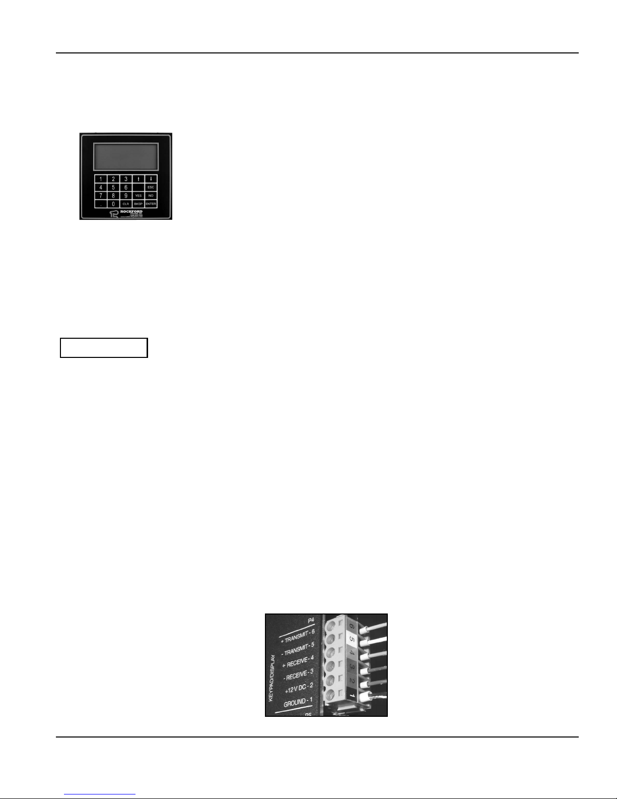
When connecting the keypad/display wires to Terminal Strip P4, please follow the wiring schematics included with the control and see Photo
3.17. Strip the wires and crimp the supplied ferrules on each wire.* Terminal Strip P4 has a color-coded number label. Match each wire with the
appropriate terminal in accordance with the wiring schematics and the color-coding. Make sure each wire is tight and making good contact with
the metal part of the ferrule.
The bare silver shield wire should be twisted and put in a larger ferrule with the black wire and connected to Terminal P4-1.
Note: There is a green wire in the keypad/display cable that is not used. Cut this wire off and discard it.
*A special crimping tool is required to properly crimp the ferrules on the wires. If you do not have one, it is available from:
Weidmuller Inc.
821 Southlake Boulevard
Richmond, Virginia 23236
Toll-Free: 1-800-849-9343
Phone: (804) 794-2877
Fax: (804) 794-0252
www.weidmuller.com
We use the Weidmuller Type PZ 3,
Part No. 056730 crimping tool.
Photo 3.17— Terminal Strip P4 Wiring Connection
on the SSC-1500 Gen II Control Module
No. 6—Blue
No. 5—White
No. 4—Orange
No. 3—Brown
No. 2—Red
No. 1— Black and Bare Silver Shield
(together in larger ferrule)
22 Call: 1-800-922-7533
Rockford Systems, LLC
SECTION 3—INSTALLATION OF COMPONENTS
SSC-1500 Gen II Part-Revolution Solid-State Control
SSC-1500 Gen II Part-Revolution Solid-State Control
SECTION 1—IN GENERAL
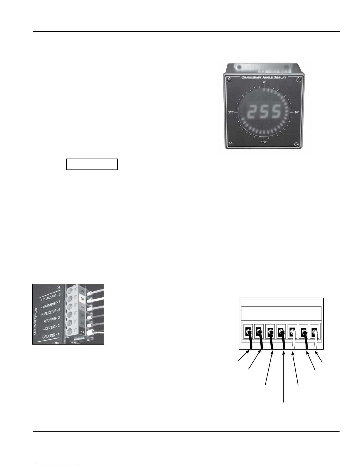
CRANKSHAFT ANGLE DISPLAY (OPTIONAL)
The crankshaft angle display, Part No. FTL-055 (photo 3.18), is an optional
unit that shows the angular position of the crankshaft both graphically (with
red LEDs in a circle) and numerically (with a large, red, three-digit LED
display). The angle display should be mounted where it is easily viewed
to help with setup, removal of stuck workpieces, or for assistance during
emergency extraction procedures.
Photo 3.18—Crankshaft Angle Display
Do not run cable in conduit or in bundles with higher
CAUTION
voltages that may cause electrical interference.
Two 25’ cables are supplied as standard and can be cut to length, if required. Do not splice the cables or interrupt the signals. If longer cables are
required, please contact the factory.
One of the cables connects between Terminal Strip P4 on the SSC-1500 Gen II control module and Terminal Strip P1 on the crankshaft angle
display. The other cable connects between Terminal Strip P2 on the crankshaft angle display and the keypad/display assembly.
When connecting Terminal Strip P1 on the crankshaft angle display wires to Terminal Strip P4 on the SSC-1500 Gen II control module, please follow
the wiring schematics included with the crankshaft angle display and see Photos 3.19 and 3.20. Strip the wires and crimp the supplied ferrules
on each wire.* Terminal Strip P4 has a color-coded number label. Match each wire with the appropriate terminal in accordance with the wiring
schematics and the color-coding. Make sure each wire is tight and is making good contact with the metal part of the ferrule. The bare silver shield
wire should be twisted and put in a larger ferrule with the black wire and connected to Terminal P4-1.
Note: There is a green wire in the keypad/display cable that is not used. Cut this wire off and discard it.
Photo 3.19— Terminal Strip P4 Wiring Connection on the
SSC-1500 Gen II Control Module
No. 6—Blue
No. 5—White
No. 4—Orange
No. 3—Brown
No. 2—Red
No. 1— Black and Bare Silver Shield
(together in larger ferrule)
*A special crimping tool is required to properly crimp the ferrules on the wires. If you do
not have one, it is available from:
Weidmuller Inc.
821 Southlake Boulevard
Richmond, Virginia 23236
Toll-Free: 1-800-849-9343
Phone: (804) 794-2877
Fax: (804) 794-0252
www.weidmuller.com
We use the Weidmuller Type PZ 3, Part No. 056730 crimping tool.
Rockford Systems, LLC
Call: 1-800-922-7533 23
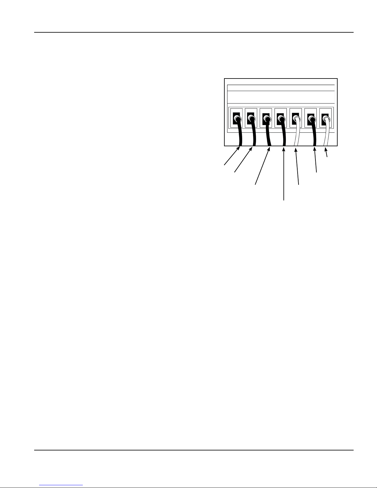
Photo 3.20— Terminal Strip P1 Wiring
Connection on the
Crankshaft Angle Display
No. 1—
Black
No. 2—
Red
No. 3—
White
No. 4—
No. 5—
Brown
Blue
(Continued on next page.)
No. 7—
Silver
No. 6—
Orange
SECTION 3—INSTALLATION OF COMPONENTS
SSC-1500 Gen II Part-Revolution Solid-State Control
CRANKSHAFT ANGLE DISPLAY (continued)
When connecting Terminal Strip P2 on the crankshaft angle display
wires to the keypad/display assembly, the existing cable that came with
the control can be used; however, if this cable is too short, discard it and
use the cable furnished with the crankshaft angle display. Please follow
the wiring schematics included with the crankshaft angle display and
see Photo 3.21. Strip the wires and crimp the supplied ferrules on each
wire.* Match each wire with the appropriate terminal in accordance with
the wiring schematics and the color-coding. Make sure each wire is tight
and is making good contact with the metal part of the ferrule.
Note: There is a green wire in these cables that is not used. Cut this
wire off and discard it.
*A special crimping tool is required to properly crimp the ferrules on the wires. If you do not have one, it is available from:
Photo 3.21—Terminal Strip P2 Wiring Connection on
the Crankshaft Angle Display
No. 1—
Black
No. 2—
Red
No. 3—
Brown
No. 5—
White
No. 4—
Orange
No. 7—
Silver
No. 6—
Blue
Weidmuller Inc.
821 Southlake Boulevard
Richmond, Virginia 23236
Toll-Free: 1-800-849-9343
Phone: (804) 794-2877
Fax: (804) 794-0252
www.weidmuller.com
We use the Weidmuller Type PZ 3, Part No. 056730 crimping tool.
24 Call: 1-800-922-7533
Rockford Systems, LLC
SECTION 3—INSTALLATION OF COMPONENTS
SSC-1500 Gen II Part-Revolution Solid-State Control
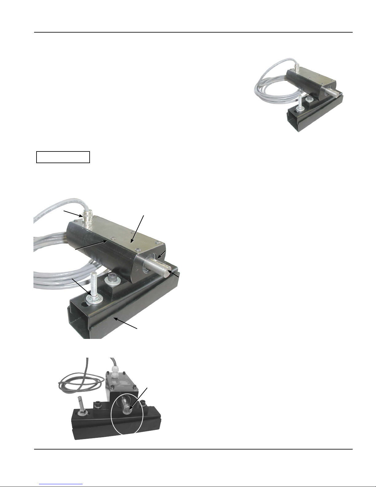
Resolver/Pulser Assembly
The absolute resolver/pulser assembly with spring-tension base is used to provide position and
velocity/motion information of the machine crankshaft to the control. The resolver is a highly
accurate and repeatable timing device. The resolver/pulser is contained in a rugged, heavyduty housing with a spring-tension base. The 3⁄4” diameter steel shaft is mounted in sealed ball
bearings. This results in a rugged transducer assembly for press applications. The resolver/pulser
is furnished with a 40’ cable that attaches to the drive assembly and wires in to the control box.
When installing, the cable can be cut to the exact length required (do not splice). For more than
40’ of cable, please contact factory. See the next page or the enclosed wiring schematics for
proper wiring.
CAUTION
Photo 3.23
Resolver/Pulser Assembly
(Top of cover has been slid aside for photo)
Cable
Connector
Resolver
(interior)
Spring/Adjustment
Jam Nut
Do not run cable in conduit or in bundles with higher voltages that
may cause electrical interference.
The photoelectric pulser is monitored by the control logic to
verify proper resolver position. Position changes can occur either
mechanically or electrically. A mechanical failure can result if the
resolver slips, and an electrical failure can result within the resolver
Pulser
(interior)
3
⁄16”
Keyway
3
⁄4” Shaft
cabling or circuitry. If failure occurs, the resolver position and the
pulser cam signal will not match and the circuit logic will detect
the fault. The pulser cam and resolver are connected internally
to the connector provided; therefore, no wiring is necessary. The
resolver/pulser is factory arranged for clockwise (CW) rotation
(when facing the end of the shaft). A wiring change is required for
counterclockwise (CCW) rotation. See the bottom of the next page
or the enclosed wiring schematics for further details.
After installation of the resolver/pulser and wiring is complete
with the machine at TDC (top dead center), perform the power-up
procedure in Section 4 on page 44. This will automatically detect
the pulser cam and set up the resolver for normal operation.
Cable
Photo 3.22
Part No. CMS-115
Resolver/Pulser Assembly
Photo 3.24
Resolver With Keyway in Correct Position
Rockford Systems, LLC
Call: 1-800-922-7533 25
Spring-Loaded Base
Keyway
When installing a chain and sprocket or drive coupling to the
3
⁄4” shaft, start with the machine at TDC (top dead center) and
the keyway pointing up, perpendicular to the base (Photo 3.24).
Connect the chain to sprockets or tighten the drive coupling. (See
next page for sprocket and chain drive).
Note: If the resolver assembly is mounted on an angle or even
upside down from what is illustrated, be sure the keyway
on the shaft is always perpendicular to the base. The
keyway must always be turned 180° away from the base
when initially setting up the machine. The crankshaft of the
machine must be at TDC.
(Continued on next page.)
SECTION 3—INSTALLATION OF COMPONENTS
SSC-1500 Gen II Part-Revolution Solid-State Control
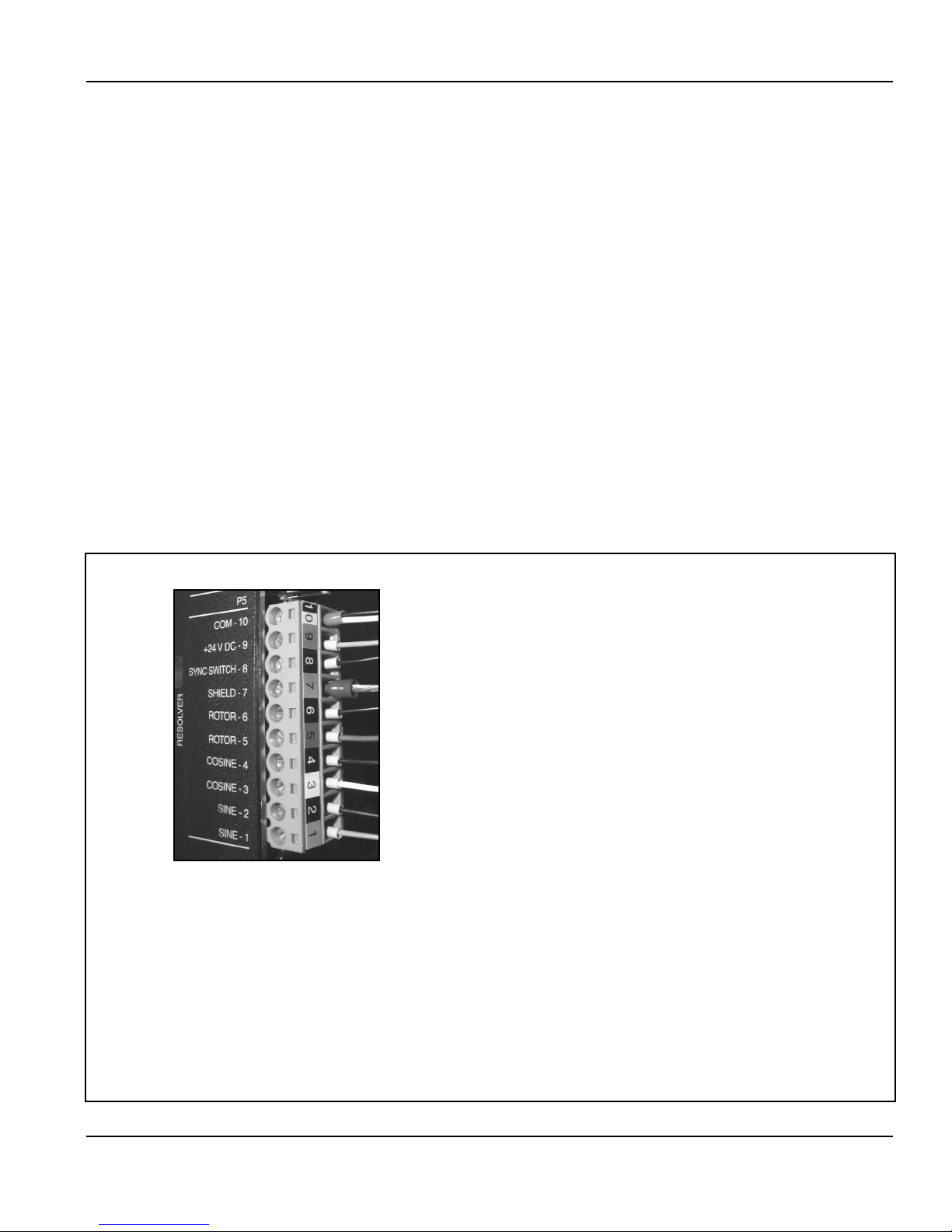
CONNECTING THE RESOLVER WIRES TO TERMINAL STRIP P5
When connecting the resolver wires to Terminal Strip P5, please follow the wiring schematics included with the control and see Photo 3.25. Strip
the wires and crimp the supplied ferrules on each wire.* Terminal Strip P5 has a color-coded number label. Match each wire with the appropriate
terminal in accordance with the wiring schematics and the color-coding. Make sure each wire is tight and making good contact with the metal part
of the ferrule.
Forty feet of cable is supplied as standard and can be cut to length, if required. Do not splice the cable or interrupt the signals. If a longer cable is
required, please contact the factory.
*A special crimping tool is required to properly crimp the ferrules on the wires. If you do not have one, it is available from:
Weidmuller Inc.
821 Southlake Boulevard
Richmond, Virginia 23236
Toll-Free: 1-800-849-9343
Phone: (804) 794-2877
Fax: (804) 794-0252
www.weidmuller.com
We use the Weidmuller Type PZ 3, Part No. 056730 crimping tool.
Photo 3.25—Terminal Strip P5 Wiring Connection on the SSC-1500 Gen II Control Module
10— Black & Yellow (together in one ferrule)
9— Blue
8— Black
7— Five Bare Silver Shields (twisted together in large ferrule) &
Ground (no ferrule)
6— Black
5— Red
4— Black
3— White
2— Black
1— Green
Note:
There is a brown and black wire pair with a silver shield in the resolver cable
that is not used—cut and discard.
Note: The above wiring is for the resolver shaft to rotate clockwise. If the resolver needs to rotate
counterclockwise, the white/black and green/black pairs need to be swapped, such that:
4— Black
3— Green
2— Black
1— White
paired
U
paired
U
paired
U
paired
U
paired
U
paired
U
Green Panel
26 Call: 1-800-922-7533
Rockford Systems, LLC
SECTION 3—INSTALLATION OF COMPONENTS
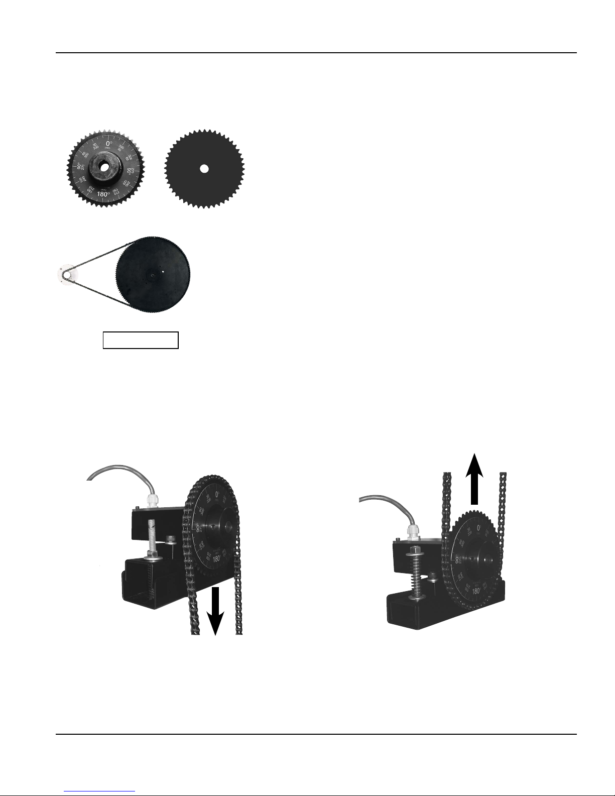
Sprocket Assembly (If furnished)
SSC-1500 Gen II Part-Revolution Solid-State Control
Photo 3.26—Part No. CML-000
Photo 3.27—Part No. CML-100
Existing sprockets may be reused, or two sprockets with an identical number of teeth
(usually 48) may be supplied. They are used to drive the resolver/pulser assembly. The
standard set consists of one sprocket with the proper bore, keyway, and setscrews to
mount directly on the shaft extension of the resolver. The other sprocket is flat with
a small rough bore. This sprocket is normally mounted on the end of the machine
crankshaft by drilling and tapping two suitable mounting holes in the sprockets and
crankshaft and using spacer blocks, if necessary, to provide clearance for the chain.
These sprockets use a standard ANSI No. 35 roller chain and connecting links.
SPECIAL SPROCKETS
If your machine does not have access to the crankshaft to provide 1:1 ratio drive for the
resolver/pulser assembly, special sprocket sets are available to match the gear drive
ratio of the machine. The smaller of the two sprockets is attached to the drive of the
machine (usually on the backshaft) and the larger sprocket is attached to the resolver/
pulser assembly.
Never hammer a sprocket or coupling on or off the resolver/pulser
CAUTION
assembly shaft —this could damage the resolver/pulser assembly. It
must be pressed on or off.
When installing the drive chain, it will be necessary to adjust the length of the chain in order to obtain proper action of the spring-loaded base of the
resolver assembly. The normal position of the two hinged plates, on the resolver/pulser assembly, is approximately parallel with each other when
the chain is installed. The spring is normally positioned between the two plates when the chain is pulling down (see Photo 3.28). When the chain
is pulling up, the spring is above the top plate (see Photo 3.29).
If a chain and sprocket drive already exists on a particular machine, it may be modified to drive the resolver. The resolver must always rotate exactly
one revolution for each revolution of the machine crankshaft, therefore, the number of sprocket teeth must always match.
Photo 3.28
Chain
Pulling
Down
Note: If the press brake has a direct-coupling drive arrangement from the press brake or other timing device, the sprockets and spring-loaded base
are not required. The spring base is furnished as a chain tightener, to help with misalignment and for shock isolation only. It is not used to
detect chain breakage. The resolver has built-in motion detection that will sense if the sprocket stops rotating.
Photo 3.29
Chain Pulling Up
Rockford Systems, LLC
Call: 1-800-922-7533 27
 Loading...