

Rockford Fosgate R150X2, R250X1, R250X4, R300X4, R400-4D Installation & Operation Manual
...Page 1

Installation & Operation
AMPLIFIERS
R150X2 R250X1
R250X4 R300X4 R400-4D
R750-1D R1200-1D
R500X1D R600-4D R600X5
Installation assistance availible at:
www.rockfordfosgate.com/rftech
Direct: (480) 967-3565 • Toll Free: (800) 669-9899
600 South Rockford Drive • Tempe, Arizona 85281 United States
ROCKFORDFOSGATE.COM
Page 2

AMPLIFIERS
R150X2 R250X1
R250X4 R300X4 R400-4D
R500X1D R600-4D R600X5
R750-1D R1200-1D
Installation & Operation
Installation assistance availible at:
Page 3
If, after reading your manual, you still have questions regarding this product, we recommend that you see your Rockford Fosgate dealer. If you need
further assistance, you can call us direct at 1-800-669-9899. Be sure to
have your serial number, model number and date of purchase available
when you call.
Safety
This symbol with “WARNING” is intended to
alert the user to the presence of important instructions. Failure to heed the instructions will
result in severe injury or death.
This symbol with “CAUTION” is intended to
alert the user to the presence of important instructions. Failure to heed the instructions can
result in injury or unit damage.
•To prevent injury and damage to the unit, please read and follow the
instructions in this manual. We want you to enjoy this system, not get
a headache.
•If you feel unsure about installing this system yourself, have it installed
by a qualified Rockford Fosgate technician.
•Before installation, disconnect the battery negative (-) terminal to
prevent damage to the unit, fire and/or possible injury.
Introduction
Specications
PRACTICE SAFE SOUND
Continuous exposure to sound pressure levels over 100dB may cause
permanent hearing loss. High powered auto sound systems may
produce sound pressure levels well over 130dB. Use common sense
and practice safe sound.
PRATIQUEZ UNE ÉCOUTE SANS RISQUES
Une exposition continue à des niveaux de pression acoustique upérieurs à
100 dB peut causer une perte d’acuité auditive permanente. Les systèmes
audio de forte puissance pour auto peuvent produire des niveaux de
pression acoustique bien au-delà de 130 dB. Faites preuve de bon sens et
pratiquez une écoute sans risques
PRACTIQUE EL SONIDO SEGURO
El contacto continuo con niveles de presión de sonido superiores a 100
dB puede causar la pérdida permanente de la audición. Los sistemas de
sonido de alta potencia para automóviles pueden producir niveles de
presión de sonido superiores a los 130 dB. Aplique el sentido común y
practique el sonido seguro.
PRAKTIZIEREN SIE SICHEREN SOUND
Fortgesetzte Geräuschdruckpegel von über 100 dB können beim
Menschen zu permanentem Hörverlust führen. Leistungsstarke
Autosoundsysteme können Geräuschdruckpegel erzeugen, die weit über
130 dB liegen. Bitte wenden Sie gesunden Menschenverstand an und
praktizieren Sie sicheren Sound.
OSSERVATE LE REGOLE DEL SUONO SENZA PERICOLI
La costante esposizione a livelli di pressione acustica al di sopra dei
100dB possono causare la perdita permanente dell’udito. I sistemi
audio ad alta potenza possono produrre livelli di pressione acustica ben
superiori ai 130dB. Si consiglia il buon senso e l’osservanza delle regole
del suono senza pericoli
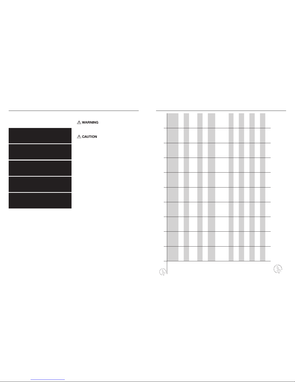
CEA 2006
Power ratings on Rockford Fosgate amplifiers conform to CEA-2006 industry standards. These guidelines
mean your amplifier’s output power ratings are REAL POWER numbers, not inflated marketing ratings.
Mode R150X2 R250X4 R300X4 R400-4D R600-4D R600X5 R250X1 R500X1D R750-1D R1200-1D
Rated Power -
Continuous
Power Rating
(RMS) Measured
@ 14.4V
50x2 @ 4 ohms
75x2 @ 2 ohms
150x1 @ 4 ohms*
40x4 @ 4 ohms
60x4 @ 2 ohms
125x2 @ 4 ohms*
50x4 @ 4 ohms
75x4 @ 2 ohms
150x2 @ 4 ohms*
75x4 @ 4 ohms
100x4 @ 2 ohms
200x2 @ 4 ohms*
100x4 @ 4 ohms
150x4 @ 2 ohms
300x2 @ 4 ohms*
50x4 @ 4 ohms
75x4 @ 2 ohms
150x2 @ 4 ohms*
Sub: 200x1 @ 4 ohms
Sub: 300x1 @ 2 ohms
150x1 @ 4 ohms
250x1 @ 2 ohms
300x1 @ 4 ohms
500x1 @ 2 ohms
250x1 @ 4 ohms
500x1 @ 2 ohms
750x1 @ 1 ohm
400x1 @ 4 ohms
800x1 @ 2 ohms
1200x1 @ 1 ohm
Crossover
Slope
12 dB/Oct 12 dB/Oct 12 dB/Oct 12 dB/Oct 12 dB/Oct 12 dB/Oct 12 dB/Oct 12 dB/Oct 12 dB/Oct 12 dB/Oct
Crossover
Frequency
Variable 50Hz-250Hz Variable 50Hz-250Hz Variable 50Hz-250Hz Variable 50Hz-250Hz Variable 50Hz-250Hz Variable 50Hz-250Hz Variable 50Hz-250Hz Variable 50Hz-250Hz Variable 50Hz-250Hz
SS: 15Hz-40Hz
Variable 50Hz-250Hz
SS: 15Hz-40Hz
Punch EQ
Variable 0 -
+
12dB @
45Hz
Selectable 0/
+
6dB/
+
12dB
@ 45Hz
Selectable 0/
+
6dB/
+
12dB
@ 45Hz
Variable 0 -
+
18dB @
45Hz
Variable 0 -
+
18dB @
45Hz
Selectable 0/
+
6dB/
+
12dB
@ 45Hz
Sub: Variable 0 -
+
12dB
@ 45Hz
Variable 0 -
+
12dB @
45Hz
Variable 0 -
+
12dB @
45Hz
Variable 0 -
+
18dB @
45Hz
Variable 0 -
+
18dB @
45Hz
Operating
Voltage
9-16VDC 9-16VDC 9-16VDC 9-16VDC 9-16VDC 9-16VDC 9-16VDC 9-16VDC 9-16VDC 9-16VDC
Frequency
Response
20Hz-20kHz 20Hz-20kHz 20Hz-20kHz 20Hz-20kHz 20Hz-20kHz 20Hz-20kHz 20Hz-250Hz 20Hz-250Hz 20Hz-250Hz 20Hz-250Hz
Battery Fuse
Rating (not
supplied)
20A 50A 50A 50A 100A 80A 30A 50A 100A 150A
THD+N @
Rated Power
<1.0% @ 4 ohms
<1.0% @ 2 ohms
<1.0% @ 4 ohms
<1.0% @ 2 ohms
<1.0% @ 4 ohms
<1.0% @ 2 ohms
<1.0% @ 4 ohms
<1.0% @ 2 ohms
<1.0% @ 4 ohms
<1.0% @ 2 ohms
F/R:
<1.0% @ 4 ohms
<1.0% @ 2 ohms
Sub:
<1.0% @ 4 ohms
<1.0% @ 2 ohms
<1.0% @ 4 ohms
<1.0% @ 2 ohms
<1.0% @ 4 ohms
<1.0% @ 2 ohms
<1.0% @ 4 ohms
<1.0% @ 2 ohms
<1.0% @ 1 ohm
<1.0% @ 4 ohms
<1.0% @ 2 ohms
<1.0% @ 1 ohm
Input Sensitivity
150mV-4V Low Level
450mV-12V High Level
150mV-4V Low Level
450mV-12V High Level
150mV-4V Low Level
450mV-12V High Level
150mV-4V 150mV-4V 150mV-4V Low Level
450mV-12V High Level
150mV-4V Low Level
450mV-12V High Level
150mV-4V Low Level
450mV-12V High Level
150mV-4V 150mV-4V
Input Imped-
ance
20k 20k 20k 20k 20k 20k 20k 20k 20k 20k
S/N Ratio CEA
2006
>80dB >80dB >80dB >70dB >70dB F/R: > 80dB
Sub: >80dB
>80dB >80dB >75dB >75dB
S/N Ratio @
Rated Power
>100dB >100dB >100dB >90dB >90dB F/R: >100dB
Sub: >100dB
>100dB >100dB >100dB >100dB
Channel
Separation
>50dB >50dB >50dB >50dB >50dB >50dB N/A N/A N/A N/A
Common Mode
Rejection Ratio
>40dB >55dB >40dB >55dB >55dB >55dB >40dB >55dB >55dB >55dB
Damping Factor
>200dB >200dB >200dB >200dB >200dB F/R: >200dB
Sub: >200dB
>200dB >200dB >200dB >200dB
Dimensions
(LxWxH)
11.2”
x
6.8”
x
2”
(28.5cm x 17.2cm x 5.1 cm)
11.2”
x
6.8”
x
2”
(28.5cm x 17.2cm x 5.1 cm)
13.2”
x
6.8”
x
2”
(33.5cm x 17.2cm x 5.1 cm)
9.1”
x
6.8”
x
2”
(23.1cm x 17.2cm x 5.1 cm)
11.1”
x
6.8”
x
2”
(28.2cm x 17.2cm x 5.1 cm)
13.2”
x
6.8”
x
2”
(33.5cm x 17.2cm x 5.1 cm)
11.2”
x
6.8”
x
2”
(28.5cm x 17.2cm x 5.1 cm)
8.5”
x
6.8”
x
2”
(21.6cm x 17.2cm x 5.1 cm)
9.1”
x
6.8”
x
2”
(23.1cm x 17.2cm x 5.1 cm)
11.1”
x
6.8”
x
2”
(28.2cm x 17.2cm x 5.1 cm)
* Rated power when amplifier is wired in a bridged configuration.
Page 4

REMGND B+
BRIDGEDBRIDGED
+–+
–
RIGHTLEFT
FRONT
+–+
–
RIGHTLEFT
REAR
L
R
FRONT
HIGH LEVEL
INPUT
FRONTREAR
REARSUB
REMOTE PUNCH LEVEL
SUB
+
–
L+R+
L-R
-
50 250
FREQ. Hz
GAIN
1
3 9
11
5 7
X-OVER
LP - AP - HP
PUNCH EQ.
2/4/5 CH.
SWITCH
PWR/
PRT
FRONT
50 250
FREQ. Hz
GAIN
1
3 9
11
5 7
X-OVER
LP - AP - HP
PUNCH EQ.
0dB +6dB +12
dB
0dB +6dB +12
dB
REAR
50 250
FREQ. Hz
GAIN
1
3 9
11
5 7
SUB
PUNCH EQ.
MIN MAX
PHASE
0˚ - 180˚
2 CH. - 4 CH. - 5 CH.
Design Features Design Features
illus.-1.1
Gain Control
The gain control is used to match the output of the
audio source.
Punch EQ - Selectable
This selectable control works along with the
crossover switch on the amplifier, boosting the
bass frequencies.
Variable Phase
The variable 0-180˚ phase control allows the listener
to change the arrival time of the subwoofer sound
waves relative to the same frequencies from the main
speakers.
Power/Protect LED
Power LED illuminates blue when the unit is turned on. Protect/
Thermal LED illuminates red when amplifier overheats or short
circuits. The amplifier will automatically shut down if this occurs.
Speaker Terminals
The Speaker Terminals are nickel-plated
set-screw wire connectors (+ and -) will
accommodate 8 AWG.
RCA Input/Pass-Thru Jacks
The RCA Inputs/Pass-Thru Jacks are nickel-plated to resist the signal degradation
caused by corrosion. The Pass-Thru provides a convenient source for daisy-chaining
an additional amplifier without running an extra set of RCA cables from the front of the
vehicle to the rear amplifier location.
Punch EQ - Variable
This variable control works along with the crossover
switch on the amplifier, boosting the bass frequencies.
Power/REM Terminals
The Power and Ground Terminals are nickel-plated set-screw wire connectors and will accommodate 4 AWG. The REM Terminal is a nickel-plated
set-screw wire connector and will accommodate
8 AWG.
Input Switch
Setting this switch to the connected inputs aligns the
output signal accordingly or can supplement signal to
additional channels when not connected.
Crossover Switch
Selectable switch for Low-Pass (LP) or
All Pass (AP) or High-Pass (HP)
Variable Crossover
A built-in 12dB/octave Butterworth filter with a crossover
point variable from 50Hz to 250Hz. (R750-1D & R1200-1D
have an additional 12dB/octave Infrasonic filter with a crossover point variable from 15Hz to 40Hz SS)
Remote Punch Level Control
Remotely control the subwoofer output
level of the amplifier.
High Level Inputs - Optional Inputs
Accepts High Level speaker signal when utilizing
the 4-pin Molex harness provided.
Page 5

Contents
Installation Considerations
The following is a list of tools needed for installation:
This section focuses on some of the vehicle considerations for installing your new amplifier. Pre-planning your system layout and best wiring
routes will save installation time. When deciding on the layout of your new
system, be sure that each component will be easily accessible for making
adjustments.
If you feel unsure about installing this system yourself, have it installed by
a qualified technician.
Before installation, disconnect the battery negative (-) terminal to prevent damage to the unit,
fire and/or possible injury.
Before beginning any installation, follow these
simple rules:
1. Be sure to carefully read and understand the instructions before
attempting to install the unit.
2. For safety, disconnect the negative lead from the battery prior to
beginning the installation.
3. For easier assembly, we suggest you run all wires prior to mounting
your unit in place.
4. Route all of the RCA cables close together and away from any high
current wires.
5. Use high quality connectors for a reliable installation and to minimize
signal or power loss.
•Fuse-holder and fuse. (See
specifications for fuse rating)
•Volt/Ohm Meter
•Wire strippers
•Wire crimpers
•Wire cutters
•#2 Phillips screwdriver
•Battery post wrench
•Hand held drill w/assorted bits
•Assorted connectors
•Adequate Length—Red
PowerWire
•Adequate Length—Remote
Turn-onWire
•Adequate Length—Black
GroundingWire
6. Think before you drill! Be careful not to cut or drill into gas tanks, fuel
lines, brake or hydraulic lines, vacuum lines or electrical wiring when
working on any vehicle.
7. Never run wires underneath the vehicle. Running the wires inside the
vehicle provides the best protection.
8. Avoid running wires over or through sharp edges. Use rubber or
plastic grommets to protect any wires routed through metal, especially
the firewall.
9. ALWAYS protect the battery and electrical system from damage with
proper fusing. Install the appropriate fuse holder and fuse on the +12V
power wire within 18” (45.7 cm) of the battery terminal.
10. When grounding to the chassis of the vehicle, scrape all paint from
the metal to ensure a good, clean ground connection. Grounding
connections should be as short as possible and always be connected
to metal that is welded to the main body, or chassis, of the vehicle.
Seatbelt bolts should never be used for connecting to ground.
Mounting Locations
To ensure optimal performance, mount the amplifier with at least
1” (2.54cm) of air gap around the amplifier’s heat sink to provide
proper cooling.
Trunk Mounting
Mounting the amplifier vertically or inverted will provide adequate cooling of the amplifier. Mounting the amplifier on the floor of the trunk will
provide the best cooling of the amplifier.
Passenger Compartment Mounting
Mounting the amplifier in the passenger compartment will work as long as
you provide a sufficient amount of air for the amplifier to cool itself. If you
are going to mount the amplifier under the seat of the vehicle, you must
have at least 1” (2.54cm) of air gap around the amplifier’s heatsink.
Never mount this unit in the engine compartment. Mounting the unit in the engine compartment will void your warranty.
Battery and Charging
Amplifiers will put an increased load on the vehicle’s battery and charging
system. We recommend checking your alternator and battery condition
to ensure that the electrical system has enough capacity to handle the
increased load of your stereo system. Stock electrical systems which are
in good condition should be able to handle the extra load of any Prime
Series amplifier without problems, although battery and alternator life can
be reduced slightly. To maximize the performance of your amplifier, we
suggest the use of a heavy duty battery and an energy storage capacitor.
Installation Installation
Wiring the System
If you do not feel comfortable with wiring your
new unit, please see your local Authorized
Rockford Fosgate Dealer for installation.
Before installation, disconnect the battery negative (-) terminal to prevent damage to the unit,
fire and/or possible injury.
Avoid running power wires near the low level
input cables, antenna, power leads, sensitive
equipment or harnesses. The power wires carry substantial current and could induce noise
into the audio system.
1. Plan the wire routing. Keep RCA cables close together but isolated
from the amplifier’s power cables and any high power auto accessories,
especially electric motors. This is done to prevent coupling the noise
from radiated electrical fields into the audio signal. When feeding
the wires through the firewall or any metal barrier, protect them with
plastic or rubber grommets to prevent short circuits. Leave the wires
long at this point to adjust for a precise fit at a later time.
2. Prepare the RED wire (power cable) for attachment to the amplifier by
stripping 1/2” of insulation from the end of the wire. Insert the bared
wire into the B+ terminal and tighten the set screw to secure the cable
in place.
NOTE: The B+ cable MUST be fused 18” or less from the vehicle’s battery.
Install the fuseholder under the hood and ensure connections are water
tight.
3. Trim the RED wire (power cable) within 18” of the battery and splice in
a inline fuse holder (not supplied). See Specifications for the rating of
the fuse to be used. DO NOT install the fuse at this time.
4. Strip 1/2” from the battery end of the power cable and crimp an
appropriate size ring terminal to the cable. Use the ring terminal to
connect to the battery positive terminal.
5. Prepare the BLACK wire (Ground cable) for attachment to the amplifier
by stripping 1/2” of insulation from the end of the wire. Insert the bare
wire into the GROUND terminal and tighten the set screw to secure the
cable in place. Prepare the chassis ground by scraping any paint from
the metal surface and thoroughly clean the area of all dirt and grease.
Strip the other end of the wire and attach a ring connector. Fasten the
cable to the chassis using a non-anodized screw and a star washer.
NOTE: Keep the length of the BLACK wire (Ground) as short as possible.
Always less than 30”.
6. Prepare the Remote turn-on wire for attachment to the amplifier by
stripping 1/2” of insulation from the end of the wire. Insert the bared
wire into the REMOTE terminal and tighten the set screw to secure the
wire in place. Connect the other end of the Remote wire to a switched
12 volt positive source. The switched voltage is usually taken from the
source unit’s remote amp on lead. If the source unit does not have this
output available, the recommended solution is to wire a mechanical
switch in line with a 12 volt source to activate the amplifier.
7. Securely mount the amplifier to the vehicle or amp rack. Be careful not
to mount the amplifier on cardboard or plastic panels. Doing so may
enable the screws to pull out from the panel due to road vibration or
sudden vehicle stops.
8. Connect from source signal by plugging the RCA cables into the input
jacks at the amplifier.
NOTE: All “ACTIVE” inputs must have RCA jacks connected. Switch in
2CH. position,“ACTIVE” - Front channel inputs only. Switch in 4CH.
position,“ACTIVE” - All Front and Rear channel inputs. Switch in 5CH
position,“ACTIVE” - Sub inputs for sub output. When connecting to the
5-Channel inputs, be sure to route front, rear and sub RCA cables tightly
together.
Always ensure power is off or disconnected at
the amplifier before connecting RCA cables.
Failure to do so may cause damage to the amplifier and/or connected components.
Note: When the installation requires a High Level (Speaker) input, use the
4-pin Molex connector to tie into your vehicles speaker wiring.
9. Connect the speakers. Strip the speaker wires 1/2” and insert into the
speaker terminal and tighten the set screw to secure into place. Be
sure to maintain proper speaker polarity. DO NOT chassis ground any
of the speaker leads as unstable operation may result.
10. Perform a final check of the completed system wiring to ensure that all
connections are accurate. Check all power and ground connections
for frayed wires and loose connections which could cause problems.
Install inline fuse near battery connection.
NOTE: Follow the diagrams for proper signal polarity.
This amplifier is not recommended for impedance loads below 2-Ohm stereo/4-Ohm
bridged for the front/rear channels and 2-ohm
for the sub channel. Models R750-1D and
R1200-1D are not recommended for impedance loads below 1-Ohm.
•Prime Amplifier
•Mounting Hardware
•Allen Wrench
•Punch Level Control
•4-pin Molex Connector (if
equipped)
•Installation & Operation
Manual
Page 6

Installation Installation
2-Channel (Stereo)
R150X2
2-Channel (Mono)
R150X2
illus.-2.1 illus.-2.2
PASS-THRU
Connect to inputs
of 2nd amplifier
*Installation option for
multi-amp install
B+REMGND
L
R
INPUT
+–+
–
RIGHTLEFT
BRIDGED
SPEAKERS
HIGH LEVEL
INPUT
L+R+
L-R
-
PASS-THRU
PASS-THRU
Connect to inputs
of 2nd amplifier
*Installation option for
multi-amp install
B+REMGND
L
R
INPUT
+–+
–
RIGHTLEFT
BRIDGED
SPEAKERS
HIGH LEVEL
INPUT
L+R+
L-R
-
PASS-THRU
Page 7

Installation Installation
illus.-2.3 illus.-2.4
4-Channel (Stereo)
R250X4, R300X4, R400-4D & R600-4D
4-Channel (2ch Stereo & 1ch Mono-Bridged)
R250X4, R300X4, R400-4D & R600-4D
REMGND
L
R
FRONT
B+
HIGH LEVEL
INPUT
FRONTREAR
REAR
+–+
–
RIGHTLEFT
BRIDGED
REAR
+–+
–
RIGHTLEFT
BRIDGED
FRONT
L+R+
L-R
-
REMGND
L
R
FRONT
B+
HIGH LEVEL
INPUT
FRONTREAR
REAR
+–+
–
RIGHTLEFT
BRIDGED
REAR
+–+
–
RIGHTLEFT
BRIDGED
FRONT
L+R+
L-R
-
Page 8

Installation Installation
illus.-2.5 illus.-2.6
4-Channel (2ch Mono-Bridged)
R250X4, R300X4, R400-4D & R600-4D
3-Channel (2ch Bridged & 1ch Parallel)
R600X5
REMGND
L
R
FRONT
B+
HIGH LEVEL
INPUT
FRONTREAR
REAR
+–+
–
RIGHTLEFT
BRIDGED
REAR
+–+
–
RIGHTLEFT
BRIDGED
FRONT
L+R+
L-R
-
REMGND B+
BRIDGEDBRIDGED
+–+
–
RIGHTLEFT
FRONT
+–+
–
RIGHTLEFT
REAR
L
R
FRONT
HIGH LEVEL
INPUT
FRONTREAR
REARSUB
REMOTE PUNCH LEVEL
SUB
+
–
L+R+
L-R
-
Page 9

Installation Installation
5-Channel (4ch Stereo & 1ch Mono)
R600X5
Mono Wiring
R250X1 & R500X1D
*Positive(+) and Negative(–) outputs
are wired in parallel internally.
REMGND B+
BRIDGEDBRIDGED
+–+
–
RIGHTLEFT
FRONT
+–+
–
RIGHTLEFT
REAR
L
R
FRONT
HIGH LEVEL
INPUT
FRONTREAR
REARSUB
REMOTE PUNCH LEVEL
SUB
+
–
L+R+
L-R
-
REMGND
L
R
INPUT
+
–
B+
SPEAKERS
HIGH LEVEL INPUT
REMOTE PUNCH LEVEL
L+R+
L-R
-
PASS-THRU
PASS-THRU
Connect to inputs
of 2nd amplifier
*Installation option for
multi-amp install
illus.-2.7 illus.-2.8
Page 10

Adjusting Gain
1. Turn amplifier gains to minimum (counter-clockwise).
2. Turn the source unit volume up to 7/8 maximum (or when
distortion is just inaudible).
3. Slowly increase amplifier gain control until adequate volume is
achieved.
NOTE: Best signal to noise and dynamic range are realized with gain set
to minimum. For a more in depth setting procedure, contact Rockford
Technical Support.
Avoid setting amplifier gain high as noise and
distortion will greatly increase.
Adjusting Crossover Frequency
Do the following individually for each channel.
Placing the crossover switch in the HP posi-
tion sets the amplifier to the High Pass mode,
enabling frequencies above the cut-off point to
pass, adjustable between 50-250Hz.
Placing the crossover switch in the AP position sets the amplifier to the All
Pass mode, preventing any crossover adjustment, allowing all frequencies
to pass.
Placing the crossover switch in the LP position sets the amplifier to the
Low Pass mode, enabling frequencies below the cut-off point to pass,
adjustable between 50-250Hz.
Turn the crossover adjustment knob all the way down. With the system
playing, turn the crossover adjustment knob up slowly until the desired
crossover point is achieved.
Input Switch
Setting this switch to the 2CH. position, switches the
inputs to a 2-channel mode, allowing connection to only
the front inputs with a 4-channel output.
Output controls function the same as if the amplifier was in 4-channel
mode.
All “ACTIVE” inputs must have RCA jacks connected.
Switch in 2CH. position,“ACTIVE” - Front channel inputs only.
Switch in 4CH. position,“ACTIVE” - All Front and Rear channel inputs.
Switch in 5CH. position,“ACTIVE” - All Front, Rear and Sub channel
inputs.
NOTE: When connecting to the 4-Channel inputs, be sure to route both
front and rear RCA cables tightly together.
Variable Phase
Allows you to conveniently switch the output phase of the
amplifier between 0° and 180°. This has the same effect as
physically reversing the Positive (+) and Negative (-) speaker wires.
High Level Input
High Level Inputs are used when you want to connect an amplifier to your
factory radio or an aftermarket radio that does not have low-level (RCA)
inputs. It allows you to use the signal coming from the speaker outputs as
an input source for the amplifier.
Punch EQ
This works along with the crossover switch on the amplifier. When set to
Low-Pass (LP) operation, this is a variable Bass Boost. When set to HighPass (HP) operation, this is a variable Mid-Bass and Treble Boost. When
set to All-Pass (AP) operation, both the Bass and Treble frequencies are
boosted. Set this to your personal preference while listening to the system.
Variable 0-+18dB @ 45Hz (R400-4D, R600-4D, R750-1D & R1200-1D)
Variable 0-+12dB @ 45Hz (R150X2, R250X1, R500X1D & R600X5)
Selectable: 0/+6dB/+12dB @ 45Hz (R250X4, R300X4 & R600X5)
Over excursion and subsequent damage may
occur at high levels of boost.
Remote Punch Level Control (Option)
Quick Install:
1. Using the screws supplied, install the mounting clip.
2. Slip the remote onto the mounting clip until it snaps into place.
3. Route and connect the cable to the remote and amplifier.
Operation:
4. When connected, the “Level Control” is linked and allows you to
remotely control the output level of the amplifier from the dash or
center console.
Operation
illus.-3.1
illus.-3.3
illus.-3.2
illus.-3.4
illus.-3.5
illus.-3.6
illus.-3.7
illus.-3.8
Installation
Parrallel Wiring*
R750-1D & R1200-1D
B+REMGND
+–+
–
PASS-THRU
Connect to inputs
of 2nd amplifier
*Installation option for
multi-amp install
*Paralleled internally for 1 � min. load.
illus.-2.9
 Loading...