

Rockford Fosgate Prime R250-1, Prime R500-1, R1 000-1 d, Prime R1000-1 d Installation & Operation Manual
Page 1

I
E:
TM
Mono
Amplifiers
R250-1
R500-1
R1
Installation
Installation
Instalaci6n y
Einbau und
Installazione e
000-1
et
funcionamiento
Betrieb
d
&
Operation
fonctionnement
funzionamento
Serial Number:_
0000529511-10
DateofPu
rchase:
------
Page 2
I
NT
RODUCTI
Dear
ON
Customer,
Congratulationsonyour
fanatics
neering
that
For
Authorized
(RTfI).
Great
that
Rockford
Insistonit!
To
everything
To
visit
or.
For
about
expertise,
reproduce
maximum
Please
product
your
installerisusing
Fosgate
add
the
from
getafree
our
web
in
the
U.S.
all
other
musical
hand
music
performancewerecommend
Rockford
After
finishing
site
countries,
Fosgate
read
your
and
competent
has
all,
your
touchtoyour
T-shirtstojackets.
brochureonRockford
at
www.rockfordfosgate.com
call
1-800·669·9899orFAX
Continuous
hearing loss.
High
purchaseofthe
reproductionatits
craftsmanship
with
all
the
Dealer.
warranty
installations
100%
authentic
everything
call
from
new
system
+001-480-967-3565orFAX
clarity
as
and
new
Fosgate
world's
best
and
critical
and
you
we
provide
retain
are
installation
RCA
cables
deserves
Rockford
products
1-800-398-3985.
PRACTICE
exposuretosound
powered
over
130dB, Use
auto sound systems
common
linest
brandofcar
andweare
testing
richness
have
specialized
your
receipt
onlyapieceofthe
and
nothing
Fosgate
pleased
procedures,wehave
you
deserve.
your
new
and
accessories
speaker
but
image
and
Rockford
+001-480-966-3983.
SAFE SOUNDTM
pressure
levels
sense and practice safe sound.
Rockford
training
original
puzzle
from
wiretopower
the
best
order
over
may
audio
amplifiers.AtRockford
you
chose
our
createdawide
Fosgate
through
carton
Rockford
your
accessories,
produce
Rockford
for
possible
whenitcomestoyour
wire
Rockford
100dB
may
sound
product
product
Fosgateinyour
and
Through
installedbyan
Technical
future
battery
accessories,
cause
permanent
pressure
Fosgateweare
yearsofengi-
rangeofproducts
Training
use.
system.
installation.
connectors.
which
Institute
Make
include
levels well
sure
If,
after
reading
your
Rockford
1-800-669-9899,
you
call.
The
serial
your permanent record.
recovering your
Serial
Number: _
Model
Number: _
your
manual,
Fosgate
number
dealer.Ifyou
Be
suretohave
canbefoundonthe outside01the
This
unitifitisever stolen.
you
still
have
questions
need further assistance,
your serial
will
serveasverificationofyour factory warranty
number,
TABLEOFCONTENTS
Introduction 2
Safety Instructions 3
Design Features 4
Installation 5·7
Installation Considerations 5
Mounting
Battery
Wiring
Locations, , , , , , 5
and
Charging
the
System,
, , , 6
, , 6
regarding
model
box.
this
product,werecommend that
you
can
callusdirect at
number
Please
Operation
Adjusting
Adjusting
Phase
Punch
Remote
Troubleshooting 9
Specifications
limited
and
dateofpurchase
recorditin
the
and
space
provided below
may
become
Gain
Crossover Frequency. , , 8
Switch
, , 8
Bass
Punch
Level
Control. , . , , 8
Warranty
Information
you
available
useful
see
when
as
in
8
8
8
10
11
NOT
E:
Review
each
section
Rockford
©
Fosgate,
registered trademarksortrademarksofRockford
2
for
more detailed information.
2009
Rockford Corporation.
the
Rockford
Fosgate
logo,
All
and
rights
the
reserved.
PRIME
logo
Corporation.
are
either
Page 3
GETTING
STARTED
Welcome
salesperson
please turn to the
TableofContents.
this
informationissubjecttochange
~WARNING
~CAUTION
~
CAUTION:
~
Lh
CAUTION
• qualified Rockford
to
Rockford
and
installer.
Installation Section
We,atRockford
manualiscurrent
To
prevent injury
instructionsinthis
headache.
If
you
Fosgate!
For
thoseofyou
But,aswe
This
symbol with
presence
will result
This
symbol with
presence
can
resultininjury
leel unsure about installing this system yourself,
This
manualisdesigned
who
of
this
Fosgate,
are
without notice.
have
constantly
want
manual.
worked
finding
quick
to
informationonhowtoinstall
Other information
very
new
"WARNING"
of
important instructions. Failure to
in
severe injuryordeath.
"CAUTION"
of
important instructions. Failure to
or
unit
damage.
and
damage
manual.
Fosgate
to the unit,
We want
technician.
you
provide
hardtomake
waystoimprove
is
intended to alert the user to the
is
intended to alert the user to the
please
to enjoy this system,
information
canbelocatedbyusing
sure
SAFETY
heed
heed
read
and
haveitinstalledbya
for
the owner,
this
all
the information
our product,
INSTRUCTIONS
the instructions
the instructions
follow the
not
product,
get a
the
in
this
~
CAUTION
~
A
Prime
R250-1,
Mono
Amplifier
Installation & Operation
Before installation, disconnect the battery negative
damage
to the unit, fire and/or possible injury.
R500-1orR1000-1d
Manual
Remote
Mounting
Punch
Hardware
(-)
terminal to prevent
CONTENTSOFCARTON
Level
Control
Kit
The
hardware
amplifiertothe
kit
included
vehicle.
Visit
our
with
web
each
site
amplifier
for
contains
the
latest informationonall
the
mounting
www.rockfordfosgate.com
hardware necessarytosecure
Rockford
products.
the
3
Page 4
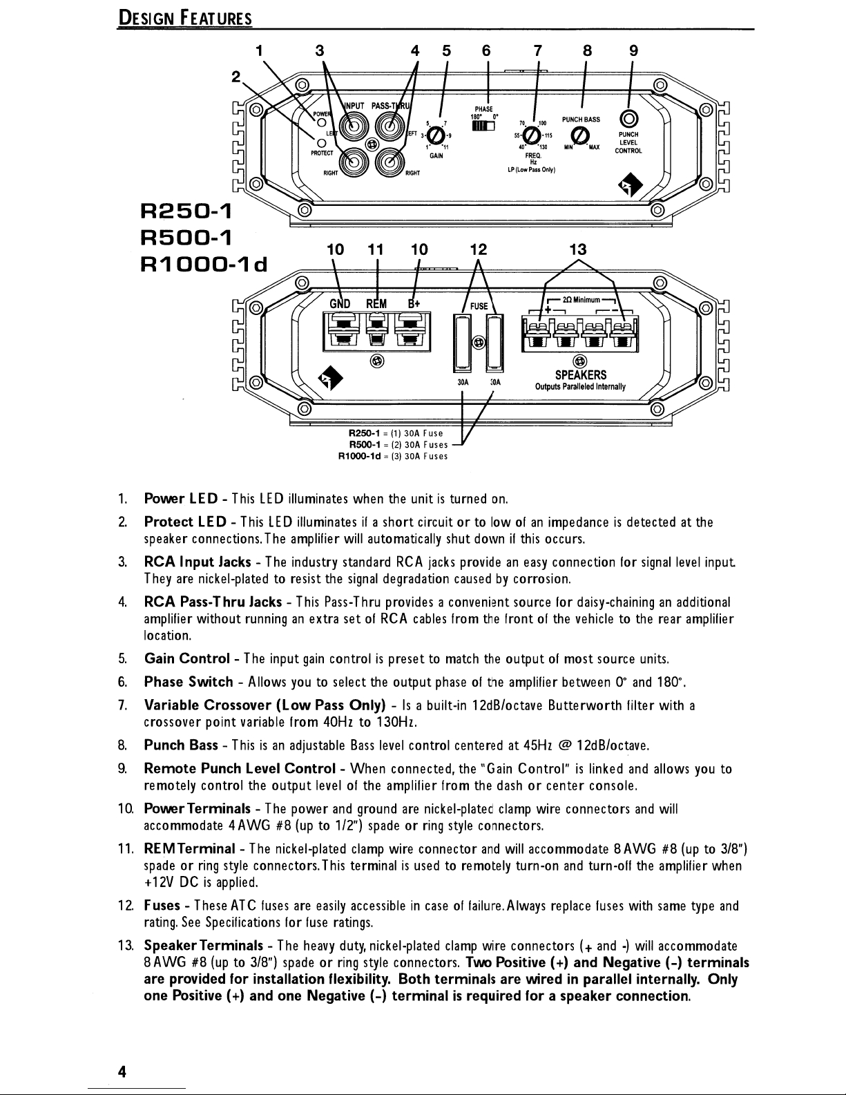
DESIGN
FEATURES
R250-1
R500-1
R1
000-1
d
1
3
10
11
R250-1 =
R500-1 =
R1000-1d =
4 5 6 7
PHASE
180'
IIIIJ
10
(1)
30A
Fuse
(2)
30A
Fuses
(3)
30A
Fuses
12
0-
70
550'115
@"
FREQ.
LP
(Low
Pass
8
100
·130
H,
Onlyl
9
PUNCH
LEVEL
CONTROL
13
1.
2.
Power
Protect
LED-This
LED-This
speaker connections.
3.
RCA Input Jacks T
hey
are
nickel-platedtoresist
4.
RCA Pass-Thru Jacks amplifier
without
runninganextra set01RCA
location.
5.
Gain
Control-The
6.
Phase
7.
Variable
crossover point
8.
Punch Bass -
9.
Remote
Switch -
Crossover
variable
Thisisan
Punch Level
remotely control the output
10.
PowerTerminals accommodate
11.
REMTerminalspadeorring
+
12VDCis
4AWG#8(up
style
applied.
LED
LED
The
The
input
Allows
illuminates
illuminatesifa short circuit ortolowofan
amplifier
industry standard
This
gain
youtoselect
when
will
the
signal
Pass-Thru
controlispresettomatch
(Low Pass Only) -Isa
Irom
40Hzto130Hz.
adjustable
Control
Bass
- When connected,
levelofthe
The
power
and
to
1/2")
The
nickel-plated
connectors.
clamp
This
terminalisusedtoremotely
the
automatically
RCA
degradation
provides
the
output
level
control centered at
amplilier
ground
are
spadeorring
wire
unitisturned
shut
jacks
on.
downifthis
provideaneasy
causedbycorrosion.
a convenient source lor
cables
from
the
front01the
the
output01most source
phaseofthe
built-in
nickel-plated
connector
12dB/octave Butterworth filter
the
"Gain
from
the
dashorcenter console.
clamp
style
connectors.
and
will
impedanceisdetectedatthe
occurs.
connection
for
daisy-chaininganadditional
vehicletothe
amplifier
between0°and
45Hz@12dB/octave.
Control"islinked
wire
connectors
accommodate
turn-on
and
8AWG#8(up
turn-off
and
and
the
signal
rear
units.
180°.
with
allows
will
amplifier
level
amplifier
a
you
input
to
to
3/8")
when
12.
Fuses rating.
13.
Speaker
8AWG#8(up
are
one
4
These
ATC
fuses
See
Specifications
Terminals -
to
The
3/8")
spadeorring
provided for installation flexibility. Both terminals
Positive (+)
and
one
are
easily
for
fuse
heavy
Negative (-)
accessibleincaseoflailure.Always
ratings.
duty,
nickel-plated
style
connectors.
clamp
Two
wire
Positive (+)
are
terminalisrequired for a
replace
connectors(+and.)will
fuses
with
same
accommodate
and
Negative (-) terminals
type
wiredinparallel internally. Only
speaker
connection.
and
Page 5
INSTALLATION CONSIDERATIONS
The
followingisa
Fuse-holder
(See
specifications
Volt/Ohm
Wire strippers
Wire crimpers
Wire cutters
Phillips
#2
This
section
Pre-planning
layoutofyour
~
CAUTION:lf
• qualified technician.
~
CAUTION:Before installation, disconnect the battery
Before
1.
2.
3.
4.
5.
6.
beginning
Be
suretocarefully
For
safety,
For easier
Route
allofthe
Use
high
Think
before
vacuum
7.
Never
protection.
8.
Avoid
running
wires routed through
9.
ALWAYS
appropriate
terminal.
10.
When
groundingtothe
ground connection. Grounding connections
metal
thatisweldedtothe
for connecting
listoftools needed
and
fuse.
for
fuse
Meter
screwdriver
focusesonsomeofthe
your system
new
any
disconnect
layout
system,besure that
you
feel
damage
to the unit, fire and/or possible injury.
installation,
read
and
the
negative
assembly,wesuggest
RCA
cables
quality
lines
run
connectors for a
you
drill!Becareful
or electrical
wires
underneath
wires
wiring
over or through sharp
metal,
protect
fuse
the
holder
battery
and
chassisofthe
to ground.
for
installation:
rating)
vehicle
and
best
unsure about installing
follow
understand
you
close
considerations
wiring
each
these
lead
from
run
together
reliable
routes
component
simple
the
rules:
instructions before attemptingtoinstall
the battery priortobeginning
all
wires
and
away
installation
not to cutordrill
when
workingonany
the
vehicle.
Running
edges.
especially
and
fuseonthe+12V
the
firewall.
electrical system
power
vehicle,
scrape
shouldbeas
main
body,orchassis,ofthe
Battery post wrench
Hand
held
drill
w/assorted
Assorted connectors
Adequate Length-Red Power Wire
Adequate Length-Remote
Adequate Length-Black Grounding Wire
for
installing
will
save
installation
willbeeasily
this
system yourself,
priortomounting
from
any
andtominimize
into
gas
tanks,
your
new
time.
accessible
negative
(-)
your unitinplace.
high
current wires.
signalorpower
fuel
lines,
amplifier.
When
for
making
haveitinstalledbya
terminal to prevent
the
installation.
brakeorhydraulic
vehicle.
the
wires
inside
the
Use
rubber or
from
damage
wire
all
paint
shortaspossible
vehicle.
within
from
vehicle
plastic
with
proper
18"
(45.7
the
Seatbelt
provides
grommetstoprotect
fusing.
cm)ofthe
metaltoensure a
and
alwaysbeconnected
bolts
should neverbeused
INSTALLATION
bits
Turn-on
decidingonthe
Install
Wire
adjustments.
the
unit
loss.
the
best
the
battery
good,
lines,
any
clean
to
MOUNTING
Engine
Never mount
Compartment
LOCATIONS
this
unitinthe
engine
your warranty.
Trunk Mounting
Mounting
Mounting
the
amplifier
the
amplifieronthe
vertically
floorofthe
compartment
or inverted
will
trunk
Mounting
provide
will
provide
the
adequate
the
unitinthe
coolingofthe
best
coolingoJthe
engine
compartment
amplifier.
amplifier.
will
void
5
Page 6
INSTALLATION
Passenger Co"¥'artment Mounting
Mounting
of
air
you
the
amplifierinthe
for
the
amplifiertocool
must
haveatleast1"(2.54cm)ofair
passenger compartment
itsell.lf
you
are
goingtomount
gap
around
will
workaslongasyou
the
the
amplifier's
amplifier
heatsink.
provide a sufficient amount
under the seatofthe
vehicle,
Mounting
the
amplilier
passenger compartment
amplifier
BATTERY
Ampliliers
checking
handle
should
and
useofa
WIRINGTHE
~
~
~
1.
2.
NOTE:The
3.
4.
5.
andisstrongly
AND
will
putanincreased
your alternator
the
increased
be
abletohandle
alternator
CAUTION:1f
CAUTION:
CAUTION:Avoid
Plan
and
noise
or
any
the
Prepare
from
B+
terminal.
Trim
supplied).
this
Strip
cable.
Prepare
insulation
attach to
heavy
the
any
from
wires
the
the
the
time.
1/2"
Use
lile
canbereduced
duty
SYSTEM
wire
routing.
high
power auto accessories.
radiated electrical
metal
barrier, protect them
longatthis
the
RED
endofthe
Tighten
B+
cable
hood
and
RED
wire
See
Specifications for the
Irom
the
ring
the
BLACK
from
the
GROU
CHARGING
loadofyour stereo system.
battery
local Authorized Rockford Fosgate Dealer
Belore installation, disconnect the battery negative (-) terminaltoprevent
damage
leads,
current
the
the
groundbyscraping
grease.
using
NOTE:Keep
Strip
the
other
a non-anodized screw
the
lengthofthe
with
less
than1"(2.54cm)ofair
will
not provide proper
cooling
gap
and
around
will
not recommended.
loadonthe
and
battery conditiontoensure that
the extra
load01any
slightly.Tomaximize
vehicle's
Stock
Prime
battery
and
the
electrical systems
Series
amplifier
the
performanceofyour
andanenergy storage capacitor.
you do
wire
MUSTbefused
ensure connections
(power
battery
terminal to connect to
endofthe
any
not
feel comfortable with wiring
to
the unit, fire and/or possible injury.
running
sensitive equipmentorharnesses. Thepower
and
Keep
point to adjust lor a precise
(power
wire.
the
screw to secure
wire
ND terminal. Tighten
paint from
endofthe
power
could induce noise into the audio system.
RCA
cables
fields
cable)
Crimp the bared
cable)
endofthe power
(Ground
wire. Crimp
and
a star
BLACK
wires near the
close
together but isolated
especially
into
with
the
plastic
electric motors.
audio
signal.
or rubber grommets to prevent short circuits.
fit
at a later time.
for attachmenttothe
wire
into a
forkorring
the
cableinplace.
18"orless
are
within
ratingofthe
cable)
the
wire
from
the
vehicle's
water tight
18"ofthe battery
lusetobe
cable
and
the
battery
positive
for attachmenttothe
the
bared
wire
the
screw to secure
metal
and
surface
attach a
and
ring
washer.
wire
(Ground)asshortaspossible.
low
When
amplifierbystripping
and
used.
crimpanappropriate
into a
thoroughly
connector.
the
amplilier's heatsinkinthe
severely affect
charging
electrical system
system.
which
the
performanceofthe
We
recommend
has
enough
areingood
condition
without problems, although battery
amplilier,wesuggest
your
new unit, please
for
installation.
level
input
cables, antenna,
wires carry substantial
from
the
amplifier's
Thisisdone to prevent
leeding
the
wires through
see
power
coupling
3/8"ofinsulation
style
connector
battery.
Install
spliceinainline
DO
NOT install
and
the
fuseholder under
fuse
holder (not
the
size
ring
terminal to
attachtothe
fuse
terminal.
amplifierbystripping
forkorring
the
cableinplace.
clean
Fasten
style
the areaofall
the
Always
3/8"
connector
Prepare
cabletothe
less
than
30"(76.2cm).
dirt
capacity
your
power
the
lirewall
Leave
of
the
chassis
and
chassis
to
the
cables
the
at
the
and
6.
Prepare
the
REMOTE
Remote
source unit's remote
recommended solution
the
Remote turn-on
endofthe
wire.
terminal.
Crimp the bared
Tighten
wiretoa switched12volt positive source.The switched
amponlead.Ifthe
istowireamechanical
amplifier.
6
wire
for attachment to
the
screw to secure
the
wire
into a
forkorring
the
wireinplace.
source unit does not
switchinline
amplilierbystripping
style
connector
Connect
the
voltageisusually
have
this
output
witha12
volt source to activate
3/8"ofinsulation
and
attach to
other
end01the
taken
available,
the
from
the
from
the
the
Page 7
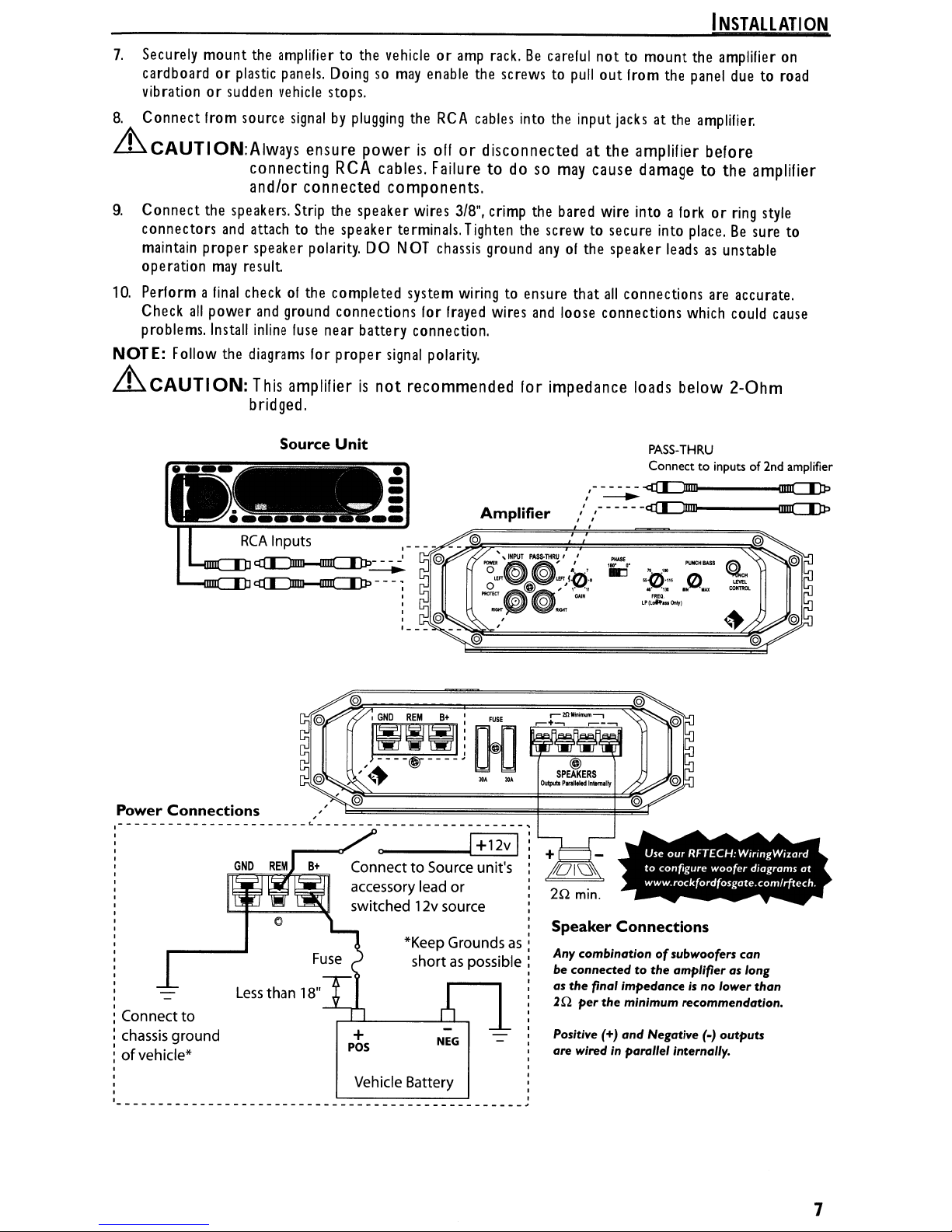
7.
Securely
cardboard or
vibrationorsudden
8.
Connect
mount
from
the
amplifiertothe
plastic
panels.
vehicle
source
vehicleoramp
Doingsomay
stops.
signalbyplugging
the
enable
RCA
rack.Becareful
the
screwstopullout
cables
into
the
nottomount the
from
input
jacksatthe
the
INSTALLATION
amplifier
panel
duetoroad
amplifier.
on
Lh.CAUTION:Always
connecting RCA cables. Failure
and/or
9.
Connect
connectors
maintain
operation
10.
Perform a
Check
problems.
NOTE:
Lh.CAUTION:
the
speakers.
and
proper speaker
may
final
all
power
Install
Follow
the
attachtothe
result
checkofthe completed system
and
inline
diagrams
This amplifierisnot
bridged.
-----
r
\
~"""
RCA
---"'""~
'"'"'"'---JL>"~---;
ensure
connected
Strip
the
speaker terminals.
polarity.
ground
connections
fuse
near battery connection.
for proper
Source
Unit
--=--
Inputs
powerisoffordisconnectedatthe amplifier before
to
do so
may
cause damage to
the
components.
speaker wires
DO
NOT
signal
•
-
-
-
-
--
__
-.'
3/8",
crimp
Tighten
chassis
ground
wiringtoensure that
for
frayed
wires
polarity.
recommended
the
bared
wire
into a
the
screwtosecure
anyofthe speaker
all
connections
and
loose connections
lor
impedance loads below
PASS-THRU
Connecttoinputsof2nd amplifier
,,-~~
" ,- -----
I I
I
forkorring
into
place.Besure
leadsasunstable
are
which
amplifier
style
accurate.
could
2-0hm
to
cause
Power
_______________________
Connections
Connect to
chassis ground
ofvehicle*
I
I
L ,
~
Connect to Source unit's
accessory lead or
12v
*Keep
short
Battery
source
Groundsas:
as
possible:
NEG
switched
+
pos
Vehicle
I
I
I
I
I
I
I
I
I
20
I
I
I
I
I
I
I
I
I
I
I
I
I
I
I
I
I
,
I
I
,
min.
Speaker
Any combination ofsubwoofers can
connected
be
as
the
final impedance
20
per
Positive (+) and Negative
are wired in parallel internally.
Use
our
RFT£CH:
to
configure
www.rockfordfosgate.comlrftech.
Connections
to
the
amplifier as long
is
the
minimum
recommendation.
woofer
no
(0)
lower
outputs
W",ngWlZard
diagrams
than
at
7
Page 8
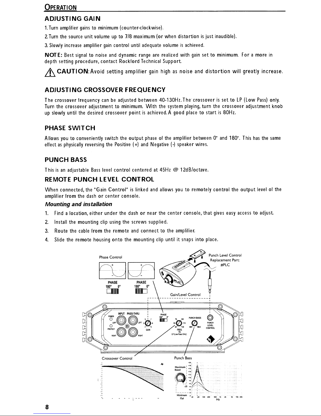
OPERATION
ADJUSTING
1.
Turn
amplifier
2.
Turn
the
3.
Slowly
increase
NOTE: Best
depth setting procedure, contact Rockford
LL
CAUTION:
GAIN
gainstominimum
source
unit
amplifier
signaltonoise
Avoid setting amplifier
(counter-clockwise).
volumeupto 7/8
gain
control
and
dynamic
maximum
until
adequate
range
Technical
(or
are
gain
highasnoise
ADJUSTING CROSSOVER FREQUENCY
The
crossover frequency
Turn
the
crossover adjustmenttominimum.
up
slowly
until
the
PHASE
Allows
SWITCH
youtoconveniently
effectasphysically
PUNCH
Thisisan
BASS
adjustable
reversing
canbeadjusted between 40-130Hz.Thecrossoverisset toLP(Low
With
the
desired crossover pointisachieved.Agood
switch
the
Bass
output
the
Positive
level
control centered at
(+)
and
phaseofthe
Negative
45Hz
when
distortionisjust
volumeisachieved.
realized
with
gain
Support
and
system
playing,
place
amplifier
(-)
speaker
@ 12dB/octave.
betweenO·and
wires.
inaudible).
set to
minimum.
distortion will greatly increase.
For a more
Pass)
turn the crossover adjustment
to startis80Hz.
180·.
This
has
the
in
only.
knob
same
REMOTE
When connected,
amplifier
PUNCH
from
LEVEL
the
"Gain
the
dashorcenter console.
Mounting and installation
1.
Find
a location, either under
2.
Install
the mounting
3.
Route
the
cable
4.
Slide
the
remote
clip
from
housing
Phase Control
the
180·
CIIIII
CONTROL
Control"islinked
the
dashornear the center console, that
using
the screws supplied.
remote
and
connecttothe
onto the mounting
PHASE
O·
PHASE
180·
IIIIJ
INPUT
PASSoTHRU
l
L£FT
and
allows
clip
untilitsnaps
O·
--------------------~
:
PtlASE
,.,.
III[J
,.
I
•
11
·0··
,"
'11
GAl,
you
to remotely control the output
gives
amplifier.
into
place.
...--:~"'"~
~
Gain/Level Control I
a Replacement Part:
T
PUNCH
BASS
a Punch
Level
#PLC
I
easy
access to adjust.
Control
levelofthe
Crossover
..
..
8
Control
Punch
Bass
.,j
.•.
-
Page 9
TROUBLESHOOTING
NOTE:
If
you
are
having
Procedure1:Check
Verify
that
POWER light
1.
Check
2.
Check
3.
Verify
necessary.
4.
Verify
connections
in-line
fuseonbattery
fuse(s)onamplifier.
that Ground connectionisconnected to
thereis9 to 14.4Volts present at
for
both
Procedure2:Protect
1.
If
the
Protect
proper speaker connections
wiring.
Too
lightison,
lowofa speaker impedance
Procedure3:Check
1.
Verify
good
RCA
input connections at stereo
splices,
2.
Disconnect
etc.
Test
RCA
RCA
input
Procedure4:Check
1.
Disconnect input
2.Ifthe
noiseiseliminated, connect
module.
signaltoamplifier
problems after installation
Amplifier
is
on.
Replaceifnecessary.
cablesatamplifier,
for
If
POWER light
positive
cable.
proper
the
stereo,
lightison.
thisisa
Amplifier
inputs for
from
Amplifierifyou
signofa possible shortinthe
and
use
a volt/ohm metertocheck
may
for
audio
AC
volts
with
amplifier.
Connect
experience
and
turn
the
REMOTE
follow
the
Troubleshooting procedures
connections.
is
on skip to Step
Replaceifnecessary.
clean
metalonthe
positive
also
battery
and
battery/fuseholder. Repair/replaceifnecessary.
cause
and
Protecttolight
output.
and
amplifier.
stereo
RCA
Check
on.
Repair/replaceifnecessary.
input
from
Turn-on
amplifieronand
leadofamplifier
below.
3,
if
not
continue.
vehicle's
remote turn-on
speaker connections. Check lor
for possible shortsinthe
entire
test stereo directly to
chassis.
lengthofcables
Repairlreplace
cable.Verify
for
amplifier
Pop.
oil.
to source unit
withadelay
if
quality
speaker
kinks,
input
turn-on
OR
1.
Use
a different 12Volt source lor
Procedure5:Check
1.
Route
all
signal
carrying
OR
2.
Bypass
directly
any
and
all
electrical components between
to
inputofamplifier.Ifnoise
OR
3.
Remove
Verify
existing
that
ground
grounding
OR
4.
Add
secondary ground
vehicle.
OR
5.
Have
alternator
electrical system
and
including
REMOTE
Amplifierifyou
wires
(RCA,
Speaker
goes
wires for
locationisclean,
cable
battery
distributor,
all
from
negative
load
testedbyyour
electrical components.
leadofamplifier.
experience
cables)
away
shiny
metal
battery terminaltothe
spark
plugs,
away
the
the
unit
freeofpaint,
mechanic.
spark
excess
stereo
being
plug
Engine
from
power
and
the
bypassedisthe
Reground
rust etc.
chassis
Verify
good
wires,
voltage
Noise.
and
ground wires.
amplifier(s).
wires to dillerent locations.
working orderofvehicle
Connect stereo
causeofthe
metalorengine
regulator etc.
noise.
block
of
9
Page 10
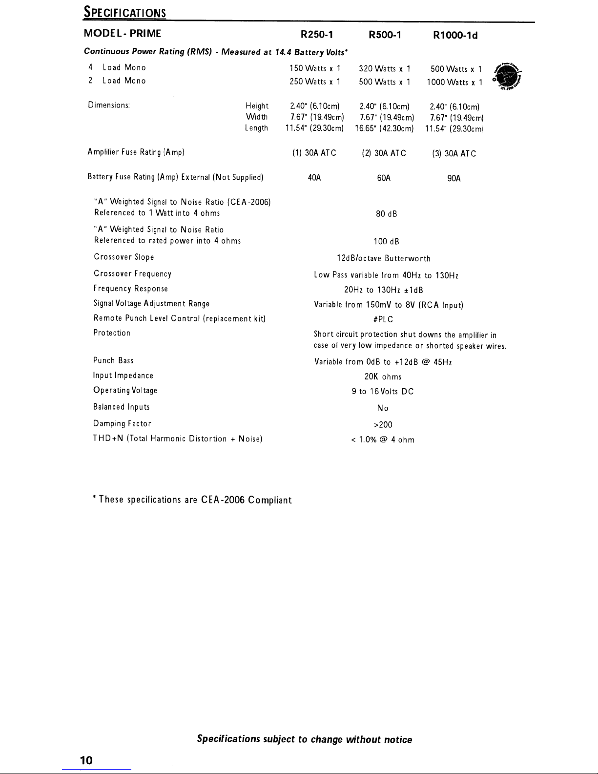
SPECIFICATIONS
MODEL- PRIME R250-1 R500-1 R1000-1d
Continuous
4
2
Dimensions:
Amplifier
Battery
"A"
Relerenced
"A"
Referencedtorated power into 4 ohms
Crossover Slope
Crossover Frequency
Frequency Response
Signal
Remote
Protection
Power Rating (RMS) •
Load
Mono
Load
Mono 250 Watts x 1 500 Watts x 1 1000 Watts x 1
Fuse
Rating
(Amp)
Fuse
Rating
(Amp)
External (Not
Weighted
Weighted
Voltage
SignaltoNoise Ratio (CEA-2006)
to
1 Watt into 4 ohms
SignaltoNoise
Adjustment
Punch
Level
Control (replacement
Ratio
Range
Measured
Height
Width
Length
Supplied)
kit)
at
14.4
Battery
150 Watts x 1
2.40"
7.67"
11.54"
(1)
Volts'
320 Watts x 1 500 Watts x 1
(6.10cm)
(19.49cm)
(29.30cm)
30A
ATC
40A
Low
Variable
Short circuit protection shut downs
caseofvery
2.40"
7.67"
16.65"
(2)
30A
100
12dB/octave Butterworth
Pass
variable from
20Hzto130Hz
from
150mVtoBV
#PLC
low
impedanceorshorted speaker
(6.10cm)
(19.49cm)
(42.30cm)
ATC
60A
80
dB
dB
2.40"
(6.10cm)
7.67"
(19.49cm)
11.54"
(29.30cm)
(3)
30A
90A
40Hzto130Hz
±1dB
(RCA
Input)
the
ATC
amplilier
o.
tr
.......
in
wires.
Punch
Bass
Input Impedance
Operating
Balanced
Damping Factor
THD+N
Voltage
Inputs
(Total
Harmonic Distortion + Noise)
• These specifications
areCEA
·2006Compliant
Variable
from
OdBto+12dB
20K
ohms
9 to 16Volts
No
>200
< 1.0% @ 4 ohm
DC
@
45Hz
Specifications
10
subjecttochange
without notice
Page 11

LIMITED
WARRANTY
INFORMATION
Rockford Corporation
following terms:
offers
a limited warrantyonRockford
LengthofWarranty
Speakers, Signal Processors,
POWERAmplifiers - 2Years
Any Factory Refurbished Product -
WhatisCovered
This
warranty
Rockford
purchasedbyconsumers
covered
applies
Fosgate
onlybythat country's Distributor
only
to Rockford
Dealersinthe
fromanAuthorized Rockford
United
WhoisCovered
This
warranty
Authorized Rockford
purchaser must provide Rockford with a
name,
product
Products
(with a product
What
is
Not Covered
covers
purchased
foundtobe
deemedtobe
only
the
Fosgate
and
defective
original purchaserofRockford product
Dealerinthe
dateofpurchase.
during
equivalent) at Rockford's discretion.
Fosgate
PRIME
Fosgate
StatesofAmerica or
the
and
PUNCH
90 days
products
and
notbyRockford Corporation.
United
copyofthe
warranty period willberepaired
(receipt
soldtoconsumersbyAuthorized
its
Fosgate
States.Inorder to
receipt
stating
productsonthe
Amplifiers - 1Year
required)
possessions.
Dealerinanother country
purchased
receive
the customer
Product
service,
or
replaced
from
name,
an
the
are
dealer
1.
Damage
2.Any costorexpense
3.
Service
Service
4.Any product
5.
Subsequent
6.Any product
7.Any product not
Lirrit
on
Any
implied
duration to
on
the
assume
causedbyaccident,
performedbyanyone
Center.
which
has
damage
purchased
purchased
IlTJ'lied
lengthofan
for
Warranties
warranties
the
periodofthe
Rockford
implied
Fosgate
Howto Obtain Service
Contact
II
you
obtain
You
the
Authorized Rockford
need
further
an
RA# (Return Authorization number) to return
are
responsible
assistance,
for shipmentofproduct to Rockford.
abuse,
related
had
the
to other components.
outside the
fromanAuthorized Rockford
including
express
warranty,sothis
any
call
improper operations,
to the removalorreinstallationofproduct
other
than
serial
number
U.S.
warrantiesoffitness
warranty
limitation
other
liabilityinconnection
Fosgate
1-800-669-9899
Rockfordoran
defaced,
for
use
set
forth
above.
may
Dealer
you
purchased
lor
Rockford Customer
water,
theft,
shipping.
Authorized Rockford
altered,orremoved.
Fosgate
and
Some
not
apply.Nopersonisauthorized
with
Dealer.
merchantability
statesdonot allow limitations
the
saleofthe
this
product from.
any
product to Rockford
are
product
Service.You
Fosgate
limited
in
to
must
Fosgate.
EU
Warranty
This
product
details.
meets
the
current
EU
warranty requirements,
see
your Authorized dealer for
11
Page 12

Installation
assistance
availible
at:
RFTEC:H
www.rockfordfosgate.com/rftech
In
U.S.A.,
11/20088.M.
09/2009
1230-56082-01
E.R.
(480) 967-3565 - C
Rockford Fosgate
RockfordCo
600
South
Tempe,Arizona
www.rockfordfosgate.com
rpo ratio n
Rockford Drive
usto
85281
mer
U.S.A.
Service
1-800-669-9899
PrintedinChina
Page 13
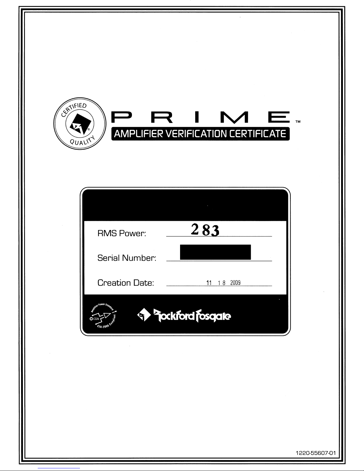
R
I
AMPLIFIER
RMS Power:
Serial Number:
Creation Date:
VERIFICATION
283
11
18
CERTIFICATE
2009
1220-55607-01
 Loading...