

Rockford Fosgate Punch P500X4D, Punch P1000X4D Installation & Operation Manual
u
N
_J
ANG
E
~ss
P500X4D
•
P1000X4D
649
Birth
Date
Date:
__
of
Purchase:
0
8
0
_
_
____
Installation
_
5
_
2
1
0
_
_
"
&
1
__
_
Operation
Introduction
Dear
Customer,
Congratulations
amplifiers.
tion
at
its
years
of
procedures,
music
with
For
maximum
Fosgate
as
we
provide
Institute
original
carton
Great
product
when
it
comes
100%
authentic
installation.
speaker
your
new
To
add
the
your
Rockford
jackets.
on
At
Rockford
best,
and
engineering
we
have
all
the
clarity
performance
product
(RTTI).
and
Rockford
wire
to
system
finishing
installed
specialized
Please
for
possible
competent
to
your
installation
power
deserves
accessories,
your
we
expertise,
touch
purchase
Fosgate
are
created a wide
and
by
training
read
system.
Fosgate
wire
of
we
pleased
hand
richness
we
recommend
an
Authorized
through
your
warranty
future
use.
installations
Make
accessories
has
everything
and
battery
nothing
to
your
new
which
include
the
world's
are
fanatics
you
chose
our
craftsmanship
range
of
products
you
deserve.
you
Rockford
Rockford
and
are
only a piece
sure
that
your
from
Rockford
from
connectors.
but
the
best.
Rockford
everything
finest
about
product.
and
have
your
Fosgate
Technical
retain
your
installer
RCA
Insist
Fosgate
from
brand
musical
Through
critical
that
reproduce
new
receipt
of
is
Fosgate
cables
on
image
T-shirts
of
car
audio
reproduc-
testing
Rockford
Dealer,
Training
and
the
puzzle
using
in
your
and
it!
After
order
to
all,
If,
after
uct,
we
further
have
your
when
you
reading
your
recommend
assistance,
serial
you
number,
call.
manual,
that
you
can
model
you
see
call
still
your
us
direct
number
have
questions
Rockford
Fosgate
at
1-800-669-9899.
and
date
regarding
dealer. If
of
purchase
this
prod-
you
need
Be
sure
available
to
Visit
our
web
site
www.
rockfordfosgate.
or,
in
the
U.S.
countries,
Table
call
of
Content
12-16
for
the
latest
information
com
call1-800-669-9899
+001-480-967
2
Introduction
Specifications
3
4-5
Design
6-9
Installation
Installation
Mounting
Battery
Wiring
Operation
10
Adjusting
2/4
Punch
Troubleshooting
11
Additional
or
-3565
or
Features
Considerations
Locations
and
Charging
the
System
Gain I Crossover
Channel
EO
Languages
French
Spanish
German
Italian
20
Limited
Warranty
on
all
Rockford
FAX
1-800-398-3985.
FAX
+001-480-966-3983.
Switch
Information
products;
For
all
other
Safety
This
symbol
to
alert
the
instructions.
will
result
This
symbol
alert
the
user
instructions.
can
result
•
To
prevent
instructions
a
headache.
•
If
you
feel
by a qualified
Before
•
prevent
with
"WARNING"
user
to
the
Failure
to
in
severe
injury
with
"CAUTION"
to
the
presence
Failure
to
in
injury
or
injury
and
in
this
unsure
about
Rockford
installation,
damage
to
presence
heed
the
or
death.
is
heed
the
unit
damage.
damage
manual.
We
installing
Fosgate
disconnect
the
unit,
tire
is
intended
of
important
instructions
intended
of
to
important
instructions
to
the
unit, please
want
you
this
system
technician
the
battery
and/or
possible
1-
WARNING
~
-+
~
CAUTION
read
to
enjoy
this
yourself,
.
negative
injury.
and
follow
system,
have
it
installed
(-)
terminal
not
the
get
to
©2011
Rockford
Corporation
Corporation.
in
the
United
All
States
Rights
and/or
Reversed.
other
countnes.
2
ROCKFORD
All
other
trademarks
FOSGATE.
PUNCH,
are
the
property
and
associated
of
their
logos
where
respective
applicable
owners.
are
registered
Specifications
subject
trademarks
to
change w thou!
of
Rockford
not1ce.
,1o-
r,,
••
/<!-t•
:..-;,..-:-
i
'J>cr;.s\7
Cf~-~~.._.,$
Conlinuous
'
Power
Measured
Rat
Ra
ed
l
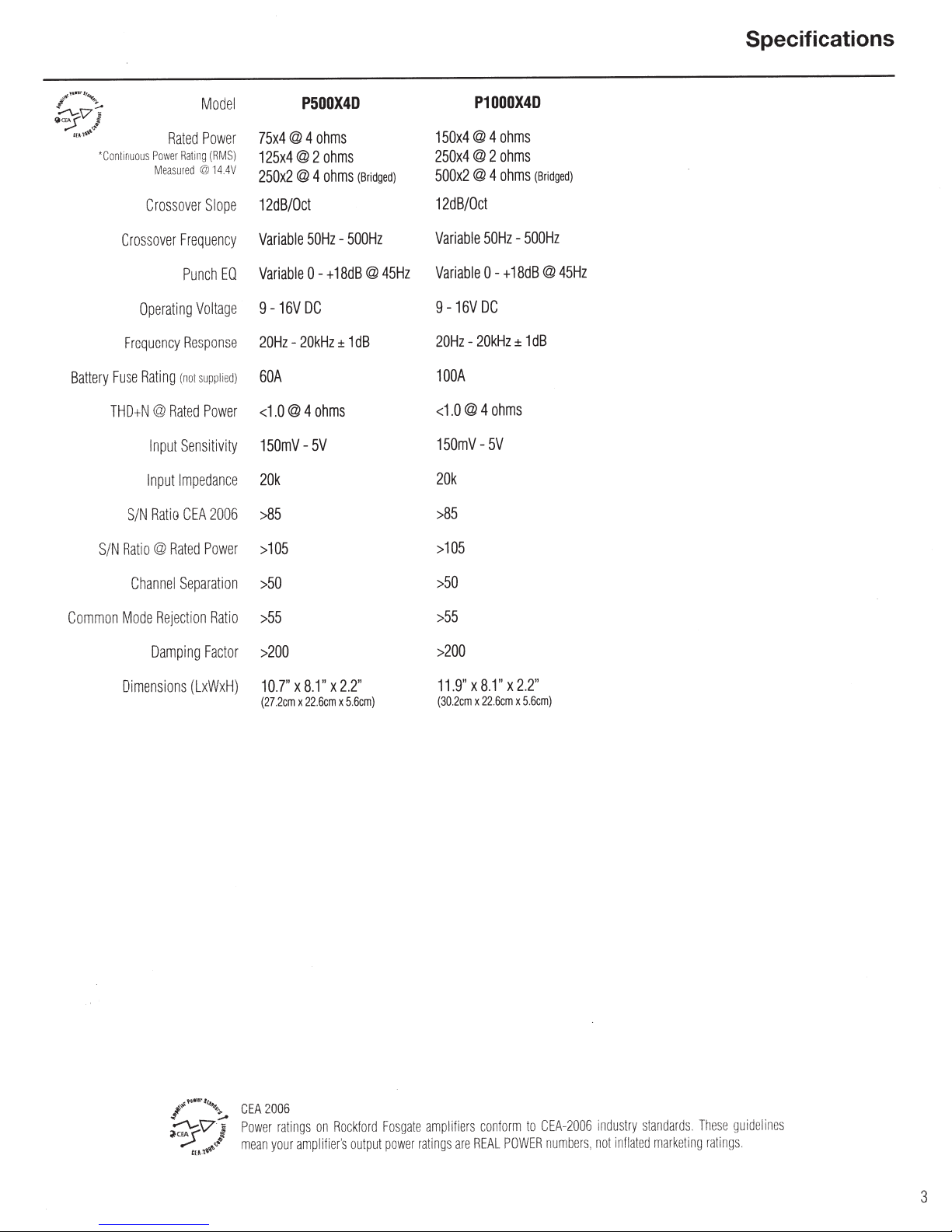
Model
Power
MS)
(R
ing
14
@
4V
75x4@
@
125x4
@ 4
250x2
P500X4D
ohms
4
ohms
2
(Bridged)
ohms
150x4
250x4
500x2
P1000X4D
ohms
@ 4
ohms
@ 2
(Br
ohms
@ 4
dged)
i
Specifications
Crossover
Fu
Battery
THDtN@
N
S/
Common
Mode R
Crossove
Frequency
Punch
Operating
Rating
(
R
no!
Frequency
se
Rated
Sensit
Input
Impe
Input
CEA
atio
R
S/N
Rated
atio@
R
Channel
Separatio
ejection
Damping
pe
Slo
r
EO
Voltage
espons
d)
ie
l
supp
wer
Po
ty
ivi
dance
2006
ower
P
Ratio
Factor
12dB/Oct
Variable
Variable
9
20Hz
e
60A
<
150mV20k
>
>
n
>50
>
>
-16V
-
1.0@
85
105
55
200
50Hz
18dB
+
0 -
DC
20kHz
ohms
4
5V
500Hz
-
@
dB
1
±
45Hz
12dB/Oct
Variable
Variable
50Hz
0 -
9-16VDC
20kHz
-
20Hz
100A
ohms
4
0@
<1.
150mV-
5V
20k
85
>
105
>
50
>
55
>
200
>
-500Hz
18dB
+
1
±
@
dB
45Hz
imen
D
ons
si
I
~'V
(LxWxH
.,,,,.
•
~,.
•••
,
..
~
)
CEA
:-.
~
Po
i
mean
-~
10.7"
(272cm
006
2
er
w
your
8.
X
22
x
ratings
mp
a
2.2"
X
1"
x
.6cm
Rockford
on
s
r'
lifie
5.6cm)
outpu
Fosgat
we
t po
e
r
amp
ra
ti
11.9"
(30.2c
fiers
li
are
ngs
8.1"
X
22.
x
m
conform
AL
RE
2.2"
X
5.6cm)
x
6cm
to
POWER
CEA
mbe
nu
-2
006
rs.
indust
in
not
standards
ry
ma
ated
fl
rk
.
eting
Tt1ese
ratings
guid
eline
s
3
Design
Features
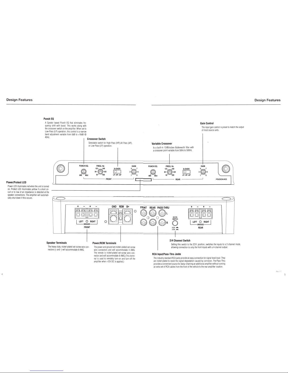
Punch
EO
A
Gyrator
based
Pun
ch
EO
that
eliminates
Ire
·
quency
shill
wi
th
boos
t.
T
his
wo
rks
along
with
t
he
crossove
r
switch
on
the
amp
lili
er.
When
set
to
Low-Pass
(LP)
operatio
n,
th
is
co
nt
rol
is
a
narrow
band
adjustmen
t
variable
from
Od
B
to
+
18dB
@
45
Hz
.
Crossover
Switch
Power/Protect
LED
Power
LED
i
ll
uminates
red
when
th
e
unit
is
t
urned
on.
P
rot
ect
LED
illuminates
yellow
if a s
ho
rt
c
ir-
cuit
or
to
low
of
an
impedan
ce
is
det
ected
at
the
speaker
co
nnections.
The
amplifier
will
automati
-
ca
lly
shu
t
down
if
this
occurs
{G
~
Speaker
Terminals
Se
le
c
tab
le swi
tch
l
or
High
-
Pass
(
HP
),A
ll
Pass
(
AP
),
or
Low
-
Pass
(
LP
)
operation
PUNCH
EQ.
FREQ
.
Hz
m
125.
.
340
60·
S
·420
MIN
MAX
so
·
·soo
FRONT
I
lEFT
~
RIGHT
I
t.....:::...:.BRIDGED
0
FRONT
I
X-OVER
llo
II
LP·HP-AP
GND
REM
B+
Power
/
REM
Terminals
GAIN
3·~:9
1'
'11
0
The
heavy
duty
,
nicke
l-
plate
d
se
t-screw
wire
con-
nectors(+
and-
) wi
ll
a
ccommo
date
8
AWG
.
The
power
and
grou
nd
are
nickel
-
pla
ted
set
-
scr
ew
w
ire
co
nne
cto
rs
and
wi
ll
accommoda
te
4
AW
G.
Th
e
remote
is
nickel-p
l
ated
set
-
sc
rew wire
co
n-
necto
r and
will
accommodate
8
AWG
.(
T
hi
s
term
i-
na
l is u
sed
to
rem
o
tely
turn-
on and
turn
-
off
the
amp
li
fi
er
wh
en
+
12V
DC
is a
pp
lied.)
Variable
Crossover
Is
a
built-in
12dB
/octave
Butte
r
wo
rth
fille
r
with
a
cro
ss
over
point
va
riab
le
from
50Hz
to
500Hz
.
Gain
Control
The
inpu
t
ga
in
cont
rol is
pres
et to ma
tch
the
o
utpu
t
of mo
st
source
units.
PUNCH
EQ
.
FREQ
.
Hz
GAIN
II
~
125.
.340
X-OVER
l·s
m-
9
m
60·
S·
420
jl
o
II
so·
·soo
LP·HP·AP
1'
'
11
MIN
MAX
REAR
P500X40
~
FR~NT
REAR
PASS·THRU
~~~
L
())
Q
21
4CH
.
~~~
R
0
4
CH
.
..a..
2CH
.
.-..
I
lEFT
0
RIGHT
I
t.....:::...:.BRI
DGE
D
REAR
2/4
Channel
Switch
Sett
i
ng
th
is
sw
i
tc
h to
th
e
2C
H pos
itio
n,
sw
i
tches
the
i
np
uts
to
a
2-chann
el
mode
,
a
ll
ow
i
ng
co
n
ne
ct
ion
to
onl
y
th
e fro
nt
inputs
w
ith
a
4-
cha
nne
l ou
tput.
RCA
lnpui/Pass·Thru
Jacks
The i
ndust
ry
stan
d
ard
RC
A ja
ck
s p
rovide
an
eas
y
connect
i
on
fo
r si
gnal
l
eve
l
in
p
ut.
Th
ey
are
nic
k
el
-p
lat
ed
to
r
es
i
st
the
sig
nal
deg
r
ad
at
i
on
ca
us
ed
by
corros
i
on
Th
e
Pass
-T
hru
pr
ov
i
des
a c
onvenient
s
ou
rce
lor
daisy
-ch
ain
in
g
an
additi
on
al
amp
li
fier wit
ho
ut
r
un
n
in
g
an
extra
se
t of R
CA
ca
bles
from
t
he
fron
t
of
the
vehi
cle
to
the
rea
r
amp
l
ifier
l
ocat
i
on.
Design
Features
illus
.-
1.1
 Loading...