

Rockford Fosgate Punch P500X4D, Punch P1000X4D, PUNCH P1000X1D Installation & Operation Manual
Installation & Operation
Printed in China
061511 BCF
1230-56751-01
P1000X4D
4CH AMPLIFIERS
P500X4D
Birth Date:
Serial Number:
Total
RMS Power
Date of Purchase:
Installation assistance availible at:
www.rockfordfosgate.com/rftech
Direct: (480) 967-3565 • Toll Free: (800) 669-9899
600 South Rockford Drive • Tempe, Arizona 85281 United States
ROCKFORDFOSGATE.COM
Introduction
Dear Customer,
Congratulations on your purchase of the world’s finest brand of car audio
amplifiers. At Rockford Fosgate we are fanatics about musical reproduction at its best, and we are pleased you chose our product. Through
years of engineering expertise, hand craftsmanship and critical testing
procedures, we have created a wide range of products that reproduce
music with all the clarity and richness you deserve.
For maximum performance we recommend you have your new Rockford
Fosgate product installed by an Authorized Rockford Fosgate Dealer,
as we provide specialized training through Rockford Technical Training
Institute (RTTI). Please read your warranty and retain your receipt and
original carton for possible future use.
Great product and competent installations are only a piece of the puzzle
when it comes to your system. Make sure that your installer is using
100% authentic installation accessories from Rockford Fosgate in your
installation. Rockford Fosgate has everything from RCA cables and
speaker wire to power wire and battery connectors. Insist on it! After all,
your new system deserves nothing but the best.
To add the finishing touch to your new Rockford Fosgate image order
your Rockford accessories, which include everything from T-shirts to
jackets.
Visit our web site for the latest information on all Rockford products;
www.rockfordfosgate.com
or, in the U.S. call 1-800-669-9899 or FAX 1-800-398-3985. For all other
countries, call +001-480-967-3565 or FAX +001-480-966-3983.
If, after reading your manual, you still have questions regarding this product, we recommend that you see your Rockford Fosgate dealer. If you need
further assistance, you can call us direct at 1-800-669-9899. Be sure to
have your serial number, model number and date of purchase available
when you call.
PRACTICE SAFE SOUND
Continuous exposure to sound pressure levels over 100dB may cause
permanent hearing loss. High powered auto sound systems may
produce sound pressure levels well over 130dB. Use common sense
and practice safe sound.
PRATIQUEZ UNE ÉCOUTE SANS RISQUES
Une exposition continue à des niveaux de pression acoustique upérieurs à
100 dB peut causer une perte d’acuité auditive permanente. Les systèmes
audio de forte puissance pour auto peuvent produire des niveaux de
pression acoustique bien au-delà de 130 dB. Faites preuve de bon sens et
pratiquez une écoute sans risques
PRACTIQUE EL SONIDO SEGURO
El contacto continuo con niveles de presión de sonido superiores a 100
dB puede causar la pérdida permanente de la audición. Los sistemas de
sonido de alta potencia para automóviles pueden producir niveles de
presión de sonido superiores a los 130 dB. Aplique el sentido común y
practique el sonido seguro.
PRAKTIZIEREN SIE SICHEREN SOUND
Fortgesetzte Geräuschdruckpegel von über 100 dB können beim
Menschen zu permanentem Hörverlust führen. Leistungsstarke
Autosoundsysteme können Geräuschdruckpegel erzeugen, die weit über
130 dB liegen. Bitte wenden Sie gesunden Menschenverstand an und
praktizieren Sie sicheren Sound.
Table of Content
2 Introduction
3 Specifications
4-5 Design Features
6-9 Installation
10 Operation
11 Troubleshooting
12-16 Additional Languages
20 Limited Warranty Information
Installation Considerations
Mounting Locations
Battery and Charging
Wiring the System
Adjusting Gain / Crossover
2/4 Channel Switch
Punch EQ
French
Spanish
German
Italian
OSSERVATE LE REGOLE DEL SUONO SENZA PERICOLI
La costante esposizione a livelli di pressione acustica al di sopra dei
100dB possono causare la perdita permanente dell’udito. I sistemi
audio ad alta potenza possono produrre livelli di pressione acustica ben
superiori ai 130dB. Si consiglia il buon senso e l’osservanza delle regole
del suono senza pericoli
Safety
This symbol with “WARNING” is intended
to alert the user to the presence of important
instructions. Failure to heed the instructions
will result in severe injury or death.
This symbol with “CAUTION” is intended to
alert the user to the presence of important
instructions. Failure to heed the instructions
can result in injury or unit damage.
•To prevent injury and damage to the unit, please read and follow the
instructions in this manual. We want you to enjoy this system, not get
a headache.
•If you feel unsure about installing this system yourself, have it installed
by a qualified Rockford Fosgate technician.
•Before installation, disconnect the battery negative (-) terminal to
prevent damage to the unit, fire and/or possible injury.
©2011 Rockford Corporation. All Rights Reversed. ROCKFORD FOSGATE, PUNCH, and associated logos where applicable are registered trademarks of Rockford
Corporation in the United States and/or other countries. All other trademarks are the property of their respective owners. Specifications subject to change without notice.
2

Specications
Model
Rated Power
*Continuous Power Rating (RMS)
Measured @ 14.4V
P500X4D P1000X4D
75x4 @ 4 ohms
125x4 @ 2 ohms
250x2 @ 4 ohms (Bridged)
150x4 @ 4 ohms
250x4 @ 2 ohms
500x2 @ 4 ohms (Bridged)
Crossover Slope 12dB/Oct 12dB/Oct
Crossover Frequency Variable 50Hz - 500Hz Variable 50Hz - 500Hz
Punch EQ Variable 0 - +18dB @ 45Hz Variable 0 - +18dB @ 45Hz
Operating Voltage 9 - 16V DC 9 - 16V DC
Frequency Response 20Hz - 20kHz ± 1dB 20Hz - 20kHz ± 1dB
Battery Fuse Rating (not supplied) 60A 100A
THD+N @ Rated Power <1.0 @ 4 ohms <1.0 @ 4 ohms
Input Sensitivity 150mV - 5V 150mV - 5V
Input Impedance 20k 20k
S/N Ratio CEA 2006 >85 >85
S/N Ratio @ Rated Power >105 >105
Channel Separation >50 >50
Common Mode Rejection Ratio >55 >55
Damping Factor >200 >200
Dimensions (LxWxH) 10.7” x 8.1” x 2.2”
(27.2cm x 22.6cm x 5.6cm)
11.9” x 8.1” x 2.2”
(30.2cm x 22.6cm x 5.6cm)
CEA 2006
Power ratings on Rockford Fosgate amplifiers conform to CEA-2006 industry standards. These guidelines
mean your amplifier’s output power ratings are REAL POWER numbers, not inflated marketing ratings.
3

Design Features
Punch EQ
A Gyrator based Punch EQ that eliminates frequency shift with boost. This works along with
the crossover switch on the amplifier. When set to
Low-Pass (LP) operation, this control is a narrow
band adjustment variable from 0dB to +18dB @
45Hz.
Crossover Switch
Selectable switch for High-Pass (HP),All Pass (AP),
or Low-Pass (LP) operation.
Power/Protect LED
Power LED illuminates red when the unit is turned
on. Protect LED illuminates yellow if a short circuit or to low of an impedance is detected at the
speaker connections. The amplifier will automatically shut down if this occurs.
Speaker Terminals
The heavy duty, nickel-plated set-screw wire connectors (+ and -) will accommodate 8 AWG.
Power/REM Terminals
The power and ground are nickel-plated set-screw
wire connectors and will accommodate 4 AWG.
The remote is nickel-plated set-screw wire connector and will accommodate 8 AWG.(This terminal is used to remotely turn-on and turn-off the
amplifier when +12V DC is applied.)
4
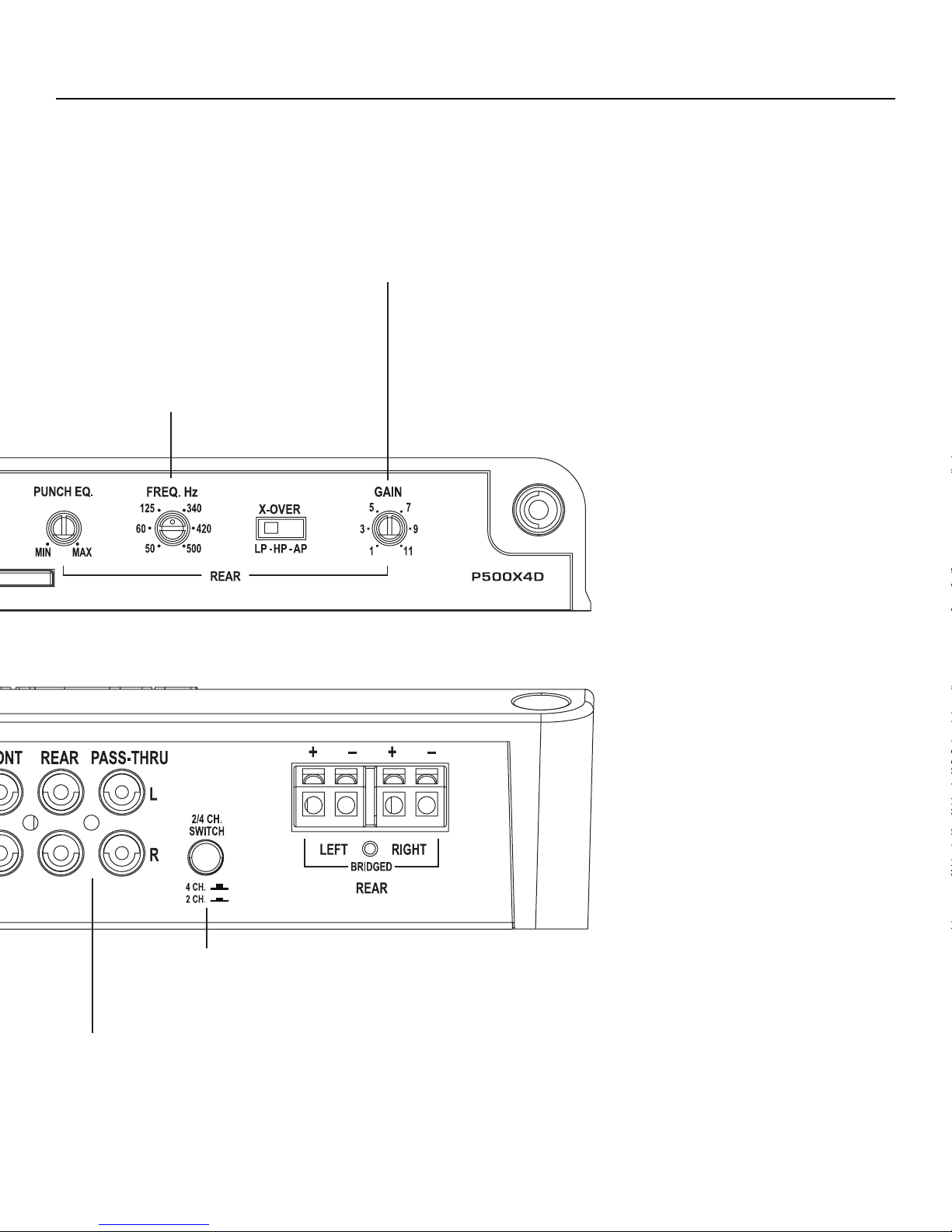
Variable Crossover
Is a built-in 12dB/octave Butterworth filter with
a crossover point variable from 50Hz to 500Hz.
Design Features
Gain Control
The input gain control is preset to match the output
of most source units.
2/4 Channel Switch
Setting this switch to the 2CH. position, switches the inputs to a 2-channel mode,
allowing connection to only the front inputs with a 4-channel output.
RCA Input/Pass-Thru Jacks
The industry standard RCA jacks provide an easy connection for signal level input. They
are nickel-plated to resist the signal degradation caused by corrosion. The Pass-Thru
provides a convenient source for daisy-chaining an additional amplifier without running
an extra set of RCA cables from the front of the vehicle to the rear amplifier location.
illus.-1.1
5

Installation
Contents
•P500X4D or P1000X4D - Punch 4 Channel Amplifier
•Mounting Hardware
•Installation & Operation Manual
Installation Considerations
The following is a list of tools needed for installation:
•Fuse-holder and fuse. (See
specifications for fuse rating)
•Volt/Ohm Meter
•Wire strippers
•Wire crimpers
•Wire cutters
•#2 Phillips screwdriver
•Battery post wrench
This section focuses on some of the vehicle considerations for installing your new amplifier. Pre-planning your system layout and best wiring
routes will save installation time. When deciding on the layout of your new
system, be sure that each component will be easily accessible for making
adjustments.
If you feel unsure about installing this system yourself, have it installed by a qualified
technician.
Before installation, disconnect the battery negative (-) terminal to prevent damage to the unit,
fire and/or possible injury.
Before beginning any installation, follow these simple rules:
•Hand held drill w/assorted bits
•Assorted connectors
•Adequate Length—Red
PowerWire
•Adequate Length—Remote
Turn-onWire
•Adequate Length—Black
GroundingWire
working on any vehicle.
7. Never run wires underneath the vehicle. Running the wires inside the
vehicle provides the best protection.
8. Avoid running wires over or through sharp edges. Use rubber or
plastic grommets to protect any wires routed through metal, especially
the firewall.
9. ALWAYS protect the battery and electrical system from damage with
proper fusing. Install the appropriate fuse holder and fuse on the +12V
power wire within 18” (45.7 cm) of the battery terminal.
10. When grounding to the chassis of the vehicle, scrape all paint from
the metal to ensure a good, clean ground connection. Grounding
connections should be as short as possible and always be connected
to metal that is welded to the main body, or chassis, of the vehicle.
Seatbelt bolts should never be used for connecting to ground.
Mounting Locations
Engine Compartment
Never mount this unit in the engine compartment. Mounting the unit in the
engine compartment will void your warranty.
Trunk Mounting
Mounting the amplifier vertically or inverted will provide adequate cooling of the amplifier. Mounting the amplifier on the floor of the trunk will
provide the best cooling of the amplifier.
Passenger Compartment Mounting
Mounting the amplifier in the passenger compartment will work as long as
you provide a sufficient amount of air for the amplifier to cool itself. If you
are going to mount the amplifier under the seat of the vehicle, you must
have at least 1” (2.54cm) of air gap around the amplifier’s heatsink.
Mounting the amplifier with less than 1” (2.54cm) of air gap around the
amplifier’s heatsink in the passenger compartment will not provide proper
cooling and will severely affect the performance of the amplifier and is
strongly not recommended.
1. Be sure to carefully read and understand the instructions before
attempting to install the unit.
2. For safety, disconnect the negative lead from the battery prior to
beginning the installation.
3. For easier assembly, we suggest you run all wires prior to mounting
your unit in place.
4. Route all of the RCA cables close together and away from any high
current wires.
5. Use high quality connectors for a reliable installation and to minimize
signal or power loss.
6. Think before you drill! Be careful not to cut or drill into gas tanks, fuel
lines, brake or hydraulic lines, vacuum lines or electrical wiring when
6
Battery and Charging
Amplifiers will put an increased load on the vehicle’s battery and charging
system. We recommend checking your alternator and battery condition
to ensure that the electrical system has enough capacity to handle the
increased load of your stereo system. Stock electrical systems which are
in good condition should be able to handle the extra load of any Prime
Series amplifier without problems, although battery and alternator life can
be reduced slightly. To maximize the performance of your amplifier, we
suggest the use of a heavy duty battery and an energy storage capacitor.
Wiring the System
If you do not feel comfortable with wiring your
new unit, please see your local Authorized
Rockford Fosgate Dealer for installation.
 Loading...