

Rockford Fosgate Punch 40I, Punch 60IX, Punch 200IX, Punch 100IX Owner's Manual

2-CHANNEL DSM AMPLIFIERS
P
UNCH
40I /
P
UNCH
60IX
P
UNCH
100IX
/
P
UNCH
200IX
OWNER’S MANUAL

Dear Customer,
Congratulations on your purchase of the world’s finest brand of car
audio amplifiers. At Rockford Fosgate we are committed to musical
reproduction at its best, and we are pleased you chose our product.
Through years of engineering expertise, hand craftsmanship and
critical testing procedures, we have created a wide range of products
that reproduce music with all the clarity and richness you deserve.
For maximum performance we recommend you have your new
Rockford
Fosgate product installed by an Authorized
Rockford
Fosgate Dealer, as we provide specialized training through Rockford
Technical Training Institute
(RTTI). Please read your warranty and
retain your receipt and original carton for possible future use.
To add the finishing touch to your new Rockford Fosgate image
order your
Rockford
accessories, which include everything from
T-
shirts and jackets to hats and sunglasses.
To get a free brochure on
Rockford
Fosgate products and
Rockford
accessories, please call 602-967-3565 or FAX 602-967-8132. In
Canada, call Korbon Trading at 905-567-1929. For International
orders, FAX
+001-l-602-967-8132
or call +001-l-602-967-3565.
PRACTICE SAFE SOUND™
CONTINUOUS EXPOSURE TO SOUND PRESSURE LEVELS OVER
1OOdB
MAY CAUSE PERMANENT HEARING LOSS. HIGH POWERED
AUTOSOUND SYSTEMS MAY PRODUCE SOUND PRESSURE LEVELS
WELL OVER 130dB. USE COMMON SENSE AND PRACTlCE SAFE SOUND.
The serial
number can be found on the outside of the box.
Please record it
in the space provided below as your permanent record. This will serve as
verification of your factory warranty and may become useful in recovering
your amplifier if it is ever stolen.
Serial Number:
Model Number:

............................................................................
8
Trunk Mounting
. . . . . . . . . . . . . . . . . . . . . . . . . . . . . . . . . . . . . . . . . . . . . . . . . . . . . . . . . . . . . . . . . . . . . . . . . . . .
8
Passenger Compartment
Mounting
. . . . . . . . . . . . . . . . . . . . . . . . . . . . . . . . . . . . . . . . . . . . . . .
8
Wiring
the System
. . . . . . . . . . . . . . . . . . . . . . . . . . . . . . . . . . . . . . . . . . . . . . . . . . . . . . . . . . . . . . . . . . . . . . . . . . . . .
9
Mono
Bridging
. . . . . . . . . . . . . . . . . . . . . . . . . . . . . . . . . . . . . . . . . . . . . . . . . . . . . . . . . . . . . . . . . . . . . . . . . . . . . . . .
11
Using the Internal Crossover
. . . . . . . . . . . . . . . . . . . . . . . . . . . . . . . . . . . . . . . . . . . . . . . . . . . . . . . . . . . .
11
Sample Wiring Diagrams
. . . . . . . . . . . . . . . . . . . . . . . . . . . . . . . . . . . . . . . . . . . . . . . . . . . . . . . . . . . . . . . . .
12
Troubleshooting
. . . . . . . . . . . . . . . . . . . . . . . . . . . . . . . . . . . . . . . . . . . . . . . . . . . . . . . . . . . . . . . . . . . . . . . . . . . . . .
15
Dynamic Power Measurements
. . . . . . . . . . . . . . . . . . . . . . . . . . . . . . . . . . . . . . . . . . . . . . . . . . . . . . .
18
Warranty
Information
. . . . . . . . . . . . . . . . . . . . . . . . . . . . . . . . . . . . . . . . . . . . . . . . . . . . . . . . . . . . . . . . . . . . . .
20
TABLE OF CONTENTS S
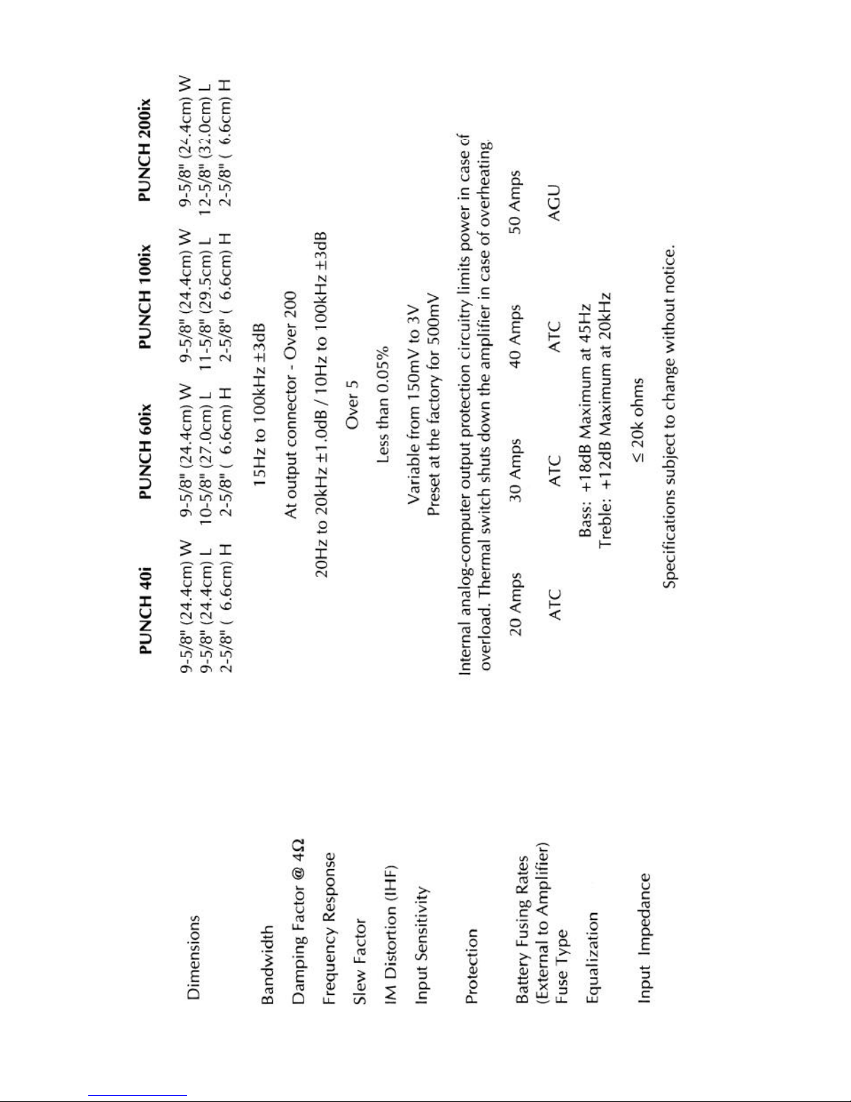
Specifications
. . . . . . . . . . . . . . . . . . . . . . . . . . . . . . . . . . . . . . . . . . . . . . . . . . . . . . . . . . . . . . . . . . . . . . . . . . . . . . . . . . . .
1
Punch Accessory
Pack
. . . . . . . . . . . . . . . . . . . . . . . . . . . . . . . . . . . . . . . . . . . . . . . . . . . . . . . . . . . . . . . . . . . . .
3
Introduction
. . . . . . . . . . . . . . . . . . . . . . . . . . . . . . . . . . . . . . . . . . . . . . . . . . . . . . . . . . . . . . . . . . . . . . . . . . . . . . . . . . . . . .
4
Operating
Features
. . . . . . . . . . . . . . . . . . . . . . . . . . . . . . . . . . . . . . . . . . . . . . . . . . . . . . . . . . . . . . . . . . . . . . .
4
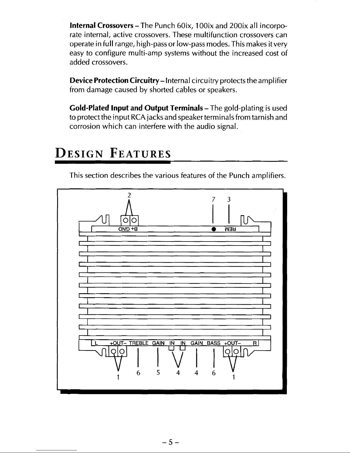
Design
Features
. . . . . . . . . . . . . . . . . . . . . . . . . . . . . . . . . . . . . . . . . . . . . . . . . . . . . . . . . . . .. . . . . . . . . . . . . . . . . . . .. .
5
Installation Considerations . . . . . . . . . . . . . . . . . . . . . . . . . . . . . . . . . . . . . . . . . . . . . . . . . . . . . . . . . . . . . . . .
7
Tools Needed
. . . . . . . . . . . . . . . . . . . . . . . . . . . . . . . . . . . . . . . . . . . . . . . . . . . . . . . . . . . . . . . . . . . . . . . . . . . . . . .
8
Battery and Charging
. . . . . . . . . . . . . . . . . . . . . . . . . . . . . . . . . . . . . . . . . . . . . . . . . . . . . . . . . . . . . . . . . . . . . . . . . . .
8
Mounting Location

-l-
-2-
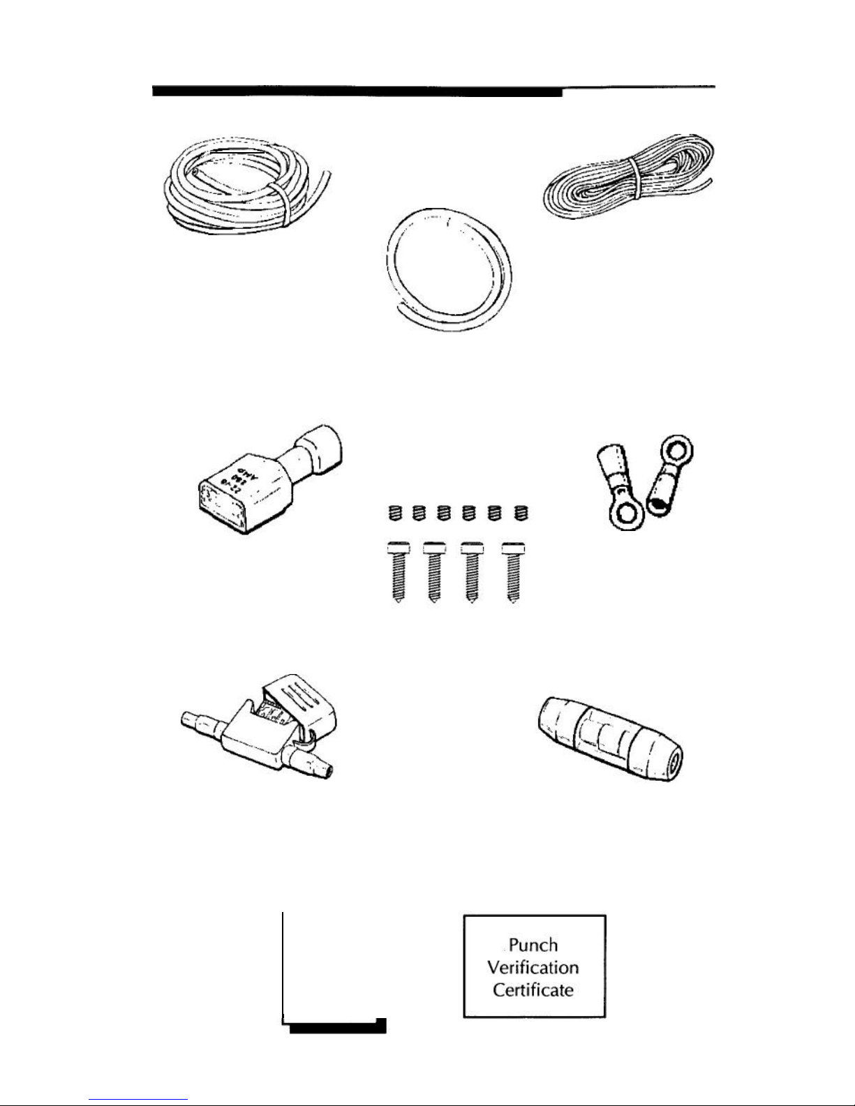
PUNCH ACCESSORY PACK
12’ (365.76cm)
Blue Remote
Turn-on Wire
17’ (518.16cm)
Red Power Wire
1.5’ (45.72cm)
Black Grounding Wire
Power Ring
Terminals
Remote Turn-on Wire
Connector Plug
Hex Head and
Mounting Screws
Power Fuse Holder with
fuse for Punch 200ix
Power Fuse Holder
with Fuse for Punch
40i,
60ix, and 100ix
Punch
Owner’s
Manual
3-

INTRODUCTION
This manual provides information on the features, installation and
operation of the Punch 40i DSM, 60ix DSM, 1
00ix
DSM and 200ix
DSM amplifiers. We suggest you save this manual for future refer-
ence.
We strongly recommend you have your Authorized Rockford Fosgate
Dealer and Service Center install the new amplifier. If you do choose
to install the amplifier yourself, please be sure to read the entire
manual before beginning.
O
PERATING
F
EATURES
The Punch 2-channel amplifiers offer unmatched quality and reliabil-
ity in high performancesound systems. The Punch amplifiers are built
using integrated Discrete Surface Mount
(DSM) technology. All
components are mounted directly on the main circuit board. This
shortens the signal path resulting in improved sound quality and
reliability. Features include:
Input level Controls -The adjustable input level controls are preset
atthefactoryto match with most popular source units. However, they
may be adjusted to allow precise matching with a wide range of
sources.
Punch Equalization Controls
-
The Punch bass and treble are finely
calibrated equalizer controls which are designed to correct for
frequency response problems found in most automobile interiors.
These controls make it possible to fine tune and adjust for the listening
environment when you are not using an external equalizer. When
used in combination with an equalizer the Punch controls should be
set to the flat position, fully counterclockwise.
Cast Aluminum
Heatsink
-
The oversized heatsink used on all the
Punch amplifiers is of cast aluminum construction. This provides
better heat dissipation to protect the circuit from thermal damage and
improve long term reliability.
End Caps- The bolt-on end caps add a visually symmetrical finish to
the amplifier. After the installation is complete, use the end caps to
cover the wires and give your system a clean, uncluttered look.
-4-
 Loading...