

Rockford Fosgate Punch 100.2, Punch 120.2, Punch 160.2, Punch 360.2, Punch 250.2 Installation & Operation Manual
...
-1-
2-channel amplifiers
Punch 100.2
Punch 120.2
Punch 160.2
Punch 250.2
Punch 360.2
Punch 500.2
Punch 800.2
Installation
& Operation
Páginas de Referencia para la Instalación
Schéma d’Installation
Installations Beiblatt
Istruzioni di Installation

Dear Customer,
Congratulations on your purchase of the world's finest brand of car audio speakers.
At Rockford Fosgate we are fanatics about musical reproduction at its best, and we
are pleased you chose our product. Through years of engineering expertise, hand
craftsmanship and critical testing procedures, we have created a wide range of products that reproduce music with all the clarity and richness you deserve.
For maximum performance we recommend you have your new Rockford Fosgate
product installed by an Authorized Rockford Fosgate Dealer, as we provide specialized training through Rockford Technical Training Institute (RTTI). Please read
your warranty and retain your receipt and original carton for possible future use.
Great product and competent installations are only a piece of the puzzle when it
comes to your system. Make sure that your installer is using 100% authentic installation accessories from Connecting Punch in your installation. Connecting Punch
has everything from RCA cables and speaker wire to Power line and battery connectors. Insist on it! After all, your new system deserves nothing but the best.
To add the finishing touch to your new Rockford Fosgate image order your Rockford
wearables, which include everything from T-shirts and jackets to hats and sunglasses.
T o get a free brochure on Rockford Fosgate products and Rockford wearables, in the
U.S. call 480-967-3565 or FAX 480-967-8132. For all other countries, call +001480-967-3565 or FAX +001-480-967-8132.
If, after reading your manual, you still have questions regarding this product, we recommend that you see your Rockford Fosgate dealer. If you need further assistance,
you can call Customer Service at 1-800-669-9899 and ask for Technical Support. Be
sure to have your serial number, model number and date of purchase available
when you call.
The serial number can be found on the outside of the box. Please record it in the
space provided below as your permanent record. This will serve as verification of
your factory warranty and may become useful in recovering your Fanatic P System
if it is ever stolen.
Serial Number: __________________________________
Model Number: __________________________________
PRACTICE SAFE SOUND™
CONTINUOUS EXPOSURE TO SOUND PRESSURE LEVELS OVER 100dB MAY CAUSE
PERMANENT HEARING LOSS. HIGH POWERED AUTOSOUND SYSTEMS MAY PRO-
DUCE SOUND PRESSURE LEVELS WELL OVER 130dB. USE COMMON SENSE AND
PRACTICE SAFE SOUND.
-1-
Specifications............................................................................................2
Introduction ..............................................................................................4
Punch Amplifier Accessory Pack ..............................................................4
2-Channel Feature Chart ..........................................................................5
Design Features ........................................................................................6
Installation Considerations......................................................................10
Mounting Location..................................................................................11
Battery and Charging ..............................................................................12
Wiring the System ..................................................................................12
Installation ..............................................................................................14
System Diagrams ....................................................................................20
Installation Troubleshooting....................................................................21
Warranty Information..............................................................................23
International Information ........................................................................24
TABLE OF CONTENTS
Sections marked
TROUBLESHOOTING
include recommendations for
curing installation problems
Sections marked
INSTALLATION
include “slam dunk”
wiring connections
Welcome to Rockford Fosgate! This manual is designed to provide
information for the owner, salesperson and installer. For those of you
who want quick information on how to install this product, please turn
to the Installation Section of this manual or refer to the icons listed
below. Other information can be located by using the Table of
Contents. We, at Rockford Fosgate, have worked very hard to make
sure all the information in this manual is current. But, as we are constantly finding new ways to improve our product, this information is
subject to change without notice.
GETTING STARTED
I
N
S
T
A
L
L
A
T
I
O
N
+ -
+ -
TROUBLE-
S
H
O
O
T
I
N
G
Visit our website for the latest information on all Rockford products.

-2-
SPECIFICATIONS
Specifications subject to change without notice
DYNAMIC POWER RATING PUNCH 100 PUNCH 120 PUNCH 160 PUNCH 250 PUNCH 360 PUNCH 500 PUNCH 800
(IHF-202 Standard) Measured at 14.4 volts
MONO into a 4 ohm load 160Wx1 200Wx1 236Wx1 320Wx1 450Wx1 710Wx1 960Wx1
PER CHANNEL into a 2 ohm load 80Wx2 94Wx2 113Wx2 160Wx2 210Wx2 330Wx2 480Wx2
PER CHANNEL into a 4 ohm load 50Wx2 64Wx2 77Wx2 100Wx2 140Wx2 210Wx2 240Wx2
CONTINUOUS POWER RATING
(MEASURED AT 13.8V)
RMS continuous power PER CHANNEL 25Wx2 30Wx2 40Wx2 62.5Wx2 90Wx2 125Wx2 200Wx2
both channels driven into a 4 ohm load
from 20 to 20,000Hz with less than 0.05%
THD+N (total Harmonic Distortion)
RMS continuous power PER CHANNEL 50Wx2 60Wx2 80Wx2 125Wx2 180Wx2 250Wx2 400Wx2
both channels driven into a 2 ohm load from
20 to 20,000Hz with less than 0.1% THD+N
(total Harmonic Distortion)
RMS continuous power MONO 100Wx1 120Wx1 160Wx1 250Wx1 360Wx1 500Wx1 800Wx1
both channels driven into a 4 ohm load
from 20 to 20,000Hz with less than 0.1%
THD+N (total Harmonic Distortion)
SIGNAL to NOISE RATIO (A-weighted) >100dB >100dB >100dB >100dB >100dB >100dB >100dB
CROSSOVER SLOPE 12DB/octave 12DB/octave 12DB/octave 12DB/octave 12DB/octave 12DB/octave 12DB/octave
CROSSOVER FREQUENCY 80Hz 80Hz 50-Hz-210Hz 50-Hz-210Hz 50-Hz-210Hz 50-Hz-210Hz 50-Hz-210Hz

-3-
SPECIFICATIONS
Specifications subject to change without notice
DIMENSIONS
(end caps installed)
PUNCH 100 PUNCH 120 PUNCH 160 PUNCH 250 PUNCH 360 PUNCH 500 PUNCH 800
2.4" 2.4" 2.4" 2.4" 2.4" 2.4" 2.4"
(6.09cm) H ((6.09cm) H (6.09cm) H (6.09cm) H (6.09cm) H (6.09cm) H (6.09cm) H
9.9" 9.9" 9.9" 9.9" 9.9" 9.9" 9.9"
(25.15cm) W (25.15cm) W (25.15cm) W (25.15cm) W (25.15cm) W (25.15cm) W (25.15cm) W
10.4" 10.4" 10.4" 11.4" 12.4" 13.4" 18.4"
(26.42 cm) L (26.42 cm) L (26.42 cm) L (28.96 cm) L (31.5 cm) L (34.04 cm) L (46.74 cm) L
FREQUENCY
RESPONSE (+ 0.5dB)
20 Hz-20kHz 20 Hz-20kHz 20 Hz-20kHz 20 Hz-20kHz 20 Hz-20kHz 20 Hz-20kHz 20 Hz-20kHz
BANDWIDTH (+ 0.3dB) 10Hz-250Hz 10Hz-200Hz 10Hz-200Hz 10Hz-200Hz 10Hz-200Hz 10Hz-200Hz 10Hz-200Hz
DAMPING FACTOR @4Ω
at output connection >200 >200 >200 >200 >200 >200 >200
SLEW RATE 30 voltsµs 30 voltsµs 30 voltsµs 30 voltsµs 30 voltsµs 30 voltsµs 30 voltsµs
IM DISTORTION <0.5% <0.5% <0.5% <0.5% <0.5% <0.5% <0.5%
SOURCE UNIT COMPATIBILITY
(+15dB gain overlap) All All All All All All All
INPUT SENSITIVITY
(0+dB gain overlap) 200mv ~ 4v 200mv ~ 4v 200mv ~ 4v 200mv ~ 4v 200mv ~ 4v 200mv ~ 4v 200mv ~ 4v
PROTECTIONNOMAD- Internal analog computer output protection circuitry limits power in case of overload. Thermal switch shuts down the amplifier in case of overheating
BATTERY FUSE RATING
(external to amplifier) 15A 20A 20A 30A 40A 50A 60A*
FUSE TYPE ATC ATC ATC ATC ATC AGU AGU
EQUALIZATION
(45Hz Punch Bass)
N/A Adjustable Variable Variable Variable Variable Variable
INPUT IMPEDANCE 20kΩ 20kΩ 20kΩ 20kΩ 20kΩ 20kΩ 20kΩ
* recommended fuse not supplied

-4-
INTRODUCTION
Rockford engineers designed the Punch 2-channel amplifiers to withstand
the rugged automotive environment while delivering superior sound quality in a flexible, reliable, and efficient package. TRANS•ANA is a low voltage circuit in the preamp stage of all Punch amplifiers that lets the music
sound crystal clear and very real, even when played at high volume levels.
This is matched with TOPAZ, a unique grounding circuit used to eliminate
noise problems associated with car audio systems and their installation.
Flexibility is accomplished with the use of a built-in crossover. The use of a
protection circuit called NOMAD, along with MOSFET and DSM (Discrete
Surface Mount) technologies improve amplifier efficiency. The result of
these components give the Punch amplifier awesome sound quality in a
“Bullet Proof” package. An explanation of these technologies, most of
which are exclusively designed and patented by Rockford, are described in
the Technical Design Features.
PUNCH AMPLIFIER ACCESSORY PACK
The accessory pack shipped with the Punch 2-channel amplifiers includes
the mounting hardware necessary to secure the amp to the vehicle and to
attach the end caps to the amplifier.
Installation & Operation Manual
Punch Verification Certificate
(4) Amplifier mounting screws (#8 x 3/4" Phillips)
(1) ATC Inline Fuseholder (Punch 120, 160, 250, 360)
(1) AGU Inline Fuseholder (Punch 500)
(2) ATC 15 Amp Fuse (Punch 100 & Punch 120)
(1) ATC 20 Amp Fuse (Punch 160)
(1) ATC 30 Amp Fuse (Punch 250)
(1) ATC 40 Amp Fuse (Punch 360)
(1) AGU 50 Amp Fuse (Punch 500)
(1) Remote Punch Bass (except Punch 100 and 120)
(1) Allen wrench 9/64”
(1) Allen wrench 3/32”
Note: Refer to the Specification section of this manual for recommended
Punch 800 fuse size.

-5-
PUNCH 2-CHANNEL AMPLIFIER FEATURE CHART
PUNCH AMPLIFIER MODEL 100 120 160 250 360 500 800
# of Channels 2 2 2 2 2 2 2
Stable into (stereo/bridged) 2Ω/4Ω 2Ω/4Ω 2Ω/4Ω 2Ω/4Ω 2Ω/4Ω 2Ω/4Ω 2Ω/4Ω
CIRCUITRY
1
TRANS•ana - circuit topology X X X X X X X
MEHSA - heat dissipating topology X X X X X X X
TOPAZ - patented noise eliminating X X X X X X X
circuitry
3
DSM - discrete surface mount X X X X X X X
MOSFETS - power supply & output devices X X X X X X
NOMAD - protection circuit X X X X X X X
FEATURES
Die Cast Heatsink X X X X X X X
Hi - level Inputs - for factory radios X X X X X X X
RCA Inputs - for after market radios X X X X X X X
Pwr/Spk Screw Terminals X X X - - - Pwr/Spk Block Terminals - - - X X X X
Adjustable Punch Bass (0.dB/+6dB/+12dB@45Hz) X - - - - Variable Punch Bass (0dB~+18dB@45Hz) (Remote) - X X X X X
Adjustable Xover (120Hz HP/80Hz LP) - X - - - - Variable Xover (50Hz - 210Hz) - - - HP/FULL/LP
4
HP/FULL/LP4HP/FULL/LP4HP/FULL/LP
4
Crossover Slope (Butterworth) 12dB 12dB 12dB 12dB 12dB 12dB 12dB
-6-
1 Additional information on features, specifications and system designs
can be found at: www.rockfordfosgate.com
2 Trans•
nova is patented under "U.S. Patent No. 4,467,288"
3 TOPAZ is patented under "U.S. Patent No. 5,751,823"
4 HP = 12dB/octave High-Pass / LP = 12dB/octave Low-Pass /
FULL = Full Range
DESIGN FEATURES
RL
Gain
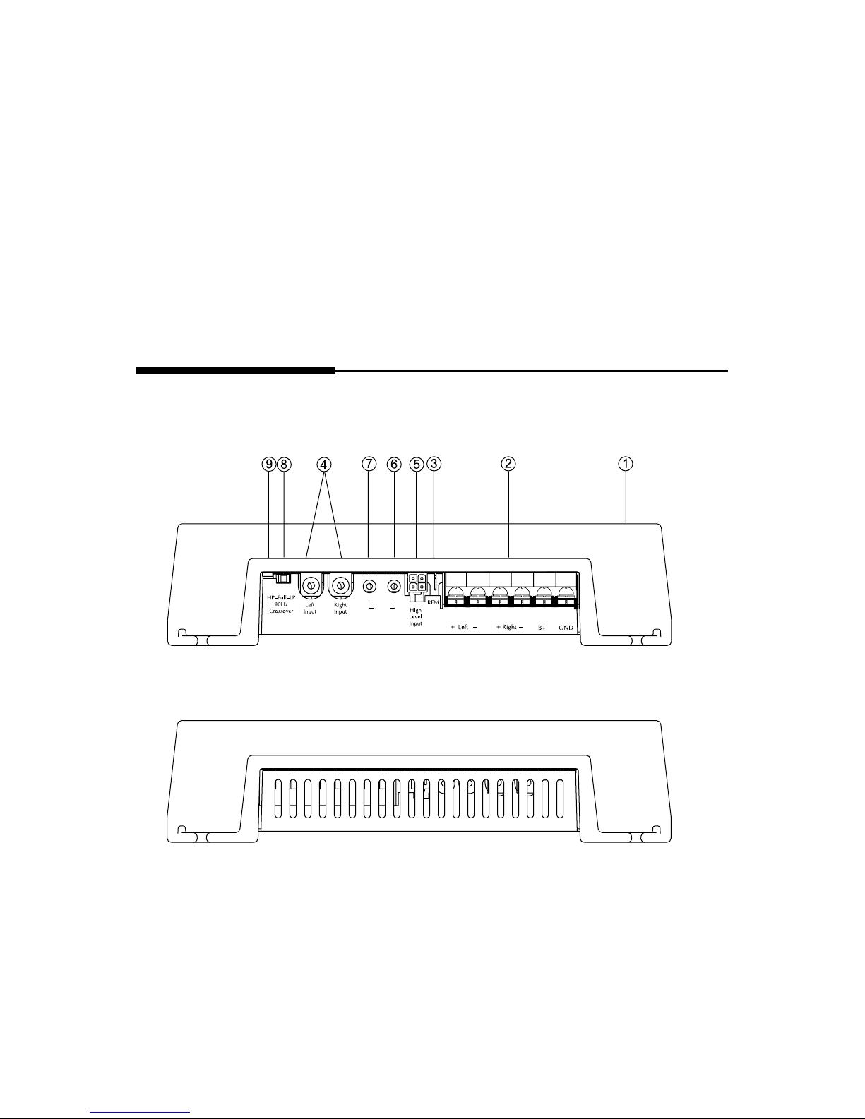
Punch 100
2-channel
-7-
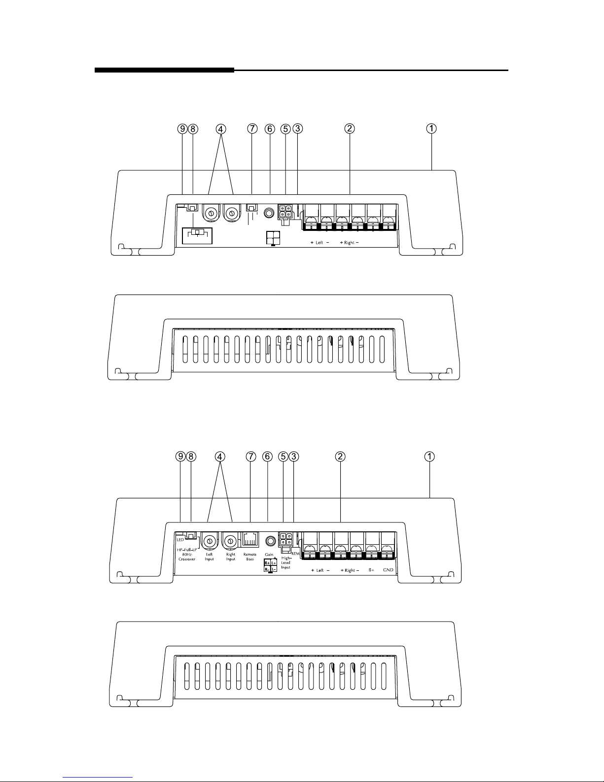
DESIGN FEATURES
REM
LED
Left Input Right Input
Gain
+12dB
+6dB
0dB
Punch
Bass
B+ GN
L+
L–
R+
R–
120HP-Full-80LP
Crossover
Punch 120
2-channel
Punch 160
2-channel
-8-
Speaker
+ L
6
8
5
5
1
21
H
14
19
L
L
R
R
HP–Full–LP
Crossover
High
Level
Input
Right
Gain
Right
Input
Left
Input
Left
Gain
Crossover
Frequency
Remote
Bass
Speaker
R
—
REM B+
GND
LED
65
80
55
50
11 0
210
Hz
145
190
Speaker
+ —
Speaker
+ R –
L+
L–
R+
R–
HP–Full–LP
Crossover
High
Level
Input
Right
Gain
Right
Input
Left
Input
Left
Gain
Crossover
Frequency
Remote
Bass
REM
B+
GND
LED
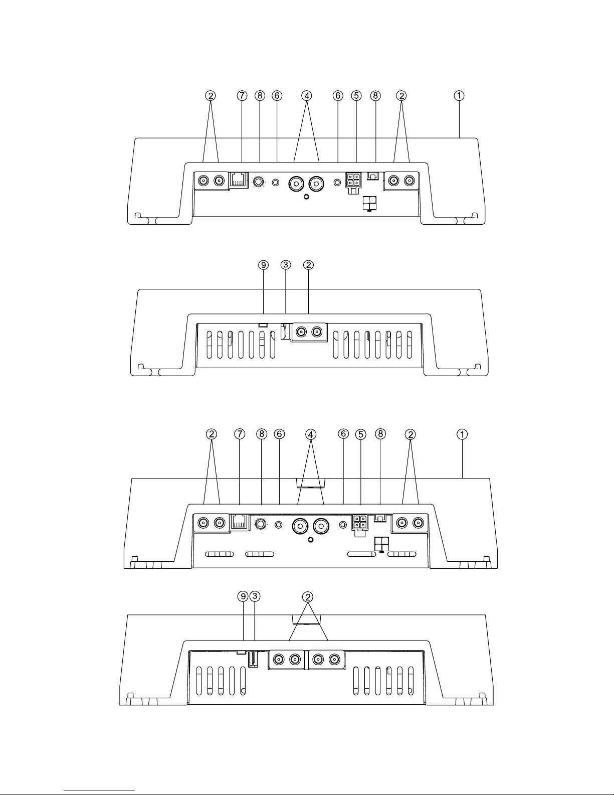
Punch 800
2-channel
Punch 250
2-channel
Punch 360
2-channel
Punch 500
2-channel

-9-
1. Cast Aluminum Heatsink – The cast aluminum heatsink of the Punch
amplifier dissipates heat generated by the amplifier's circuitry. The
inherent advantage of casting provides a 30% improvement of cooling
over conventional extrusion heatsink designs.
2. Speaker/Power Terminals – These gold-plated connectors are used for
the connection of speaker and power wire and are immune to corrosion that can cause signal degradation. The Punch 120 and Punch
160 utilize a barrier strip that will accept #10 spade lugs or bare
speaker and power wires sized from 10-18 AWG. The Punch 250,
Punch 360, Punch 500, and Punch 800 utilize heavy duty terminal
block connectors that will accept bare wires size from 8-18AWG.
3. REM Terminal – This spade terminal is used to remotely turn-on and
turn-off the amplifier when +12V DC is applied.
4. RCA Input Jacks – The industry standard RCA jack provides an easy
connection for signal level input. They are gold-plated to resist the
signal degradation caused by corrosion.
5. High Level Inputs – The high level inputs use a detachable connector
terminated with 20 AWG leads. These inputs should be used if the
source unit has only speaker line (high level) outputs and not RCA
outputs.
6. Gain Control – The input gain control is preset to match the output
of most source units. They can be adjusted to match output levels
from a variety of source units. For assistance setting the gain correctly,
contact Technical Support at 1-800-669-9899.
7. Punch Bass – The Punch Bass helps correct for acoustical deficiencies
in the listening environment. The Punch Bass allows a narrow band
adjustment at 45Hz to help reproduce full range sound without excessive boost. The Punch 120 utilizes a switch that is adjustable at
0dB/+6dB/+12dB increments. The Punch 160, Punch 250, Punch
360, Punch 500, and Punch 800 utilize a Remote Bass control that is
variable from 0dB to +18dB.
8. Internal Crossover – The internal crossover is used to delegate a spe-
cific range of frequencies to the speaker system for optimum performance. The crossover can perform three functions: High-Pass (HP),
Low-Pass (LP), or Full Range (FULL). The Punch 120 and Punch 160
utilize a 12dB/octave Butterworth crossover fixed at 120Hz HP and
80Hz LP. The Punch 250, Punch 360, Punch 500, and Punch 800 utilize a 12dB/octave Butterworth crossover variable from 50Hz to
210Hz.
9. LED Power Indicator – The LED illuminates when the unit is turned on.
 Loading...