

Rockford Fosgate PUNCH 301X, PUNCH 501X, PUNCH 801X Installation & Operation Manual

301X
501X
801X
Installation &
Operation
Installation et fonctionnement
Instalación y funcionamiento
Einbau und Betrieb
Installazione e funzionamento
4-Channel
Amplifiers

INTRODUCTION
TABLE OF CONTENTS
2
Dear Customer,
Congratulations on your purchase of the world's finest brand of car audio amplifiers. At Rockford
Fosgate we are fanatics about musical reproduction at its best, and we are pleased you chose our
product. Through years of engineering expertise, hand craftsmanship and critical testing procedures,
we have created a wide range of products that reproduce music with all the clarity and richness you
deserve.
For maximum performance we recommend you have your new Rockford Fosgate product installed
by an Authorized Rockford Fosgate Dealer, as we provide specialized training through Rockford
Technical Training Institute (RTTI). Please read your warranty and retain your receipt and original
carton for possible future use.
Great product and competent installations are only a piece of the puzzle when it comes to your
system. Make sure that your installer is using 100% authentic installation accessories from
Connecting Punch in your installation. Connecting Punch has everything from RCA cables and
speaker wire to Power line and battery connectors. Insist on it! After all, your new system deserves
nothing but the best.
To add the finishing touch to your new Rockford Fosgate image order your Rockford accessories,
which include everything from T-shirts to jackets and hats.
To get a free brochure on Rockford Fosgate products and Rockford accessories,
in the U.S. call 480-967-3565 or FAX 480-967-8132.
For all other countries, call +001-480-967-3565 or FAX +001-480-967-8132.
PRACTICE SAFE SOUND™
Continuous exposure to sound pressure levels over 100dB may cause permanent
hearing loss. High powered auto sound systems may produce sound pressure
levels well over 130dB. Use common sense and practice safe sound.
Introduction . . . . . . . . . . . . . . . . . . . . . . . . 2
Safety Instructions . . . . . . . . . . . . . . . . . . . 3
Design Features . . . . . . . . . . . . . . . . . . . . 4-5
Installation . . . . . . . . . . . . . . . . . . . . . . 5-10
Installation Considerations . . . . . . . . . . . 5
Mounting Locations. . . . . . . . . . . . . . . . 6
Battery and Charging. . . . . . . . . . . . . . . 6
Wiring the System . . . . . . . . . . . . . . . . . 6
Using Passive Crossovers . . . . . . . . . . . 10
NOTE: Review each section for more detailed information.
If, after reading your manual, you still have questions regarding this product, we recommend that
you see your Rockford Fosgate dealer. If you need further assistance, you can call us direct at
1-800-669-9899. Be sure to have your serial number, model number and date of purchase available
when you call.
The serial number can be found on the outside of the box. Please record it in the space provided
below as your permanent record. This will serve as verification of your factory warranty and may
become useful in recovering your unit if it is ever stolen.
Serial Number: _________________________________________
Model Number: ________________________________________
Operation. . . . . . . . . . . . . . . . . . . . . . . . . 11
Punch Bass (801X Only) . . . . . . . . . . . 11
Adjusting Gain . . . . . . . . . . . . . . . . . . 11
Adjusting Crossover Frequency. . . . . . . 11
Accessories. . . . . . . . . . . . . . . . . . . . . . . . 12
Troubleshooting . . . . . . . . . . . . . . . . . . . . 13
Specifications . . . . . . . . . . . . . . . . . . . . . . 14
Limited Warranty Information. . . . . . . . . . 15
International Instructions . . . . . . . . . . . . . 16
SAFETY INSTRUCTIONS
CONTENTS OF CARTON
3
Visit our web site for the latest information on all Rockford products.
GETTING STARTED
Welcome to Rockford Fosgate! This manual is designed to provide
information for the owner, salesperson and installer. For those of you who want quick information
on how to install this product, please turn to the Installation Section of this manual. Other
information can be located by using the Table of Contents. We, at Rockford Fosgate, have worked
very hard to make sure all the information in this manual is current. But, as we are constantly
finding new ways to improve our product, this information is subject to change without notice.
www.rockfordfosgate.com
This symbol with “WARNING” is intended to alert the user to the
presence of important instructions. Failure to heed the
instructions will result in severe injury or death.
This symbol with “
CAUTION” is intended to alert the user to the
presence of important instructions. Failure to heed the
instructions can result in injury or unit damage.
CAUTION: To prevent injury and damage to the unit, please read and follow the
instructions in this manual. We want you to have enjoyment from this
system, not a headache.
CAUTION If you feel unsure about installing this system yourself, have it installed
by a qualified Rockford Fosgate technician.
CAUTION Before installation, disconnect the battery negative (-) terminal to
prevent damage to the unit, fire and/or possible injury.
!
!
!
Either a Model 301X, 501X or 801X Punch
4-Channel Amplifier
Installation & Operation Manual
Mounting Hardware Kit
1 3/32" Allen Wrench
1 7/64" Allen Wrench
2 High Level Input Harnesses
1 Terminal Connector for REM power wire
1 Fuse Connector (301X & 501X Only)
1 30 Amp Fuse (301X)
1 50 Amp Fuse (501X)
The hardware kit included with each amplifier contains the mounting hardware necessary to secure
the amplifier to the vehicle and to attach the end caps to the amplifier.
NOTE: Refer to the specifications section for recommended fuse sizes for Model 801X
4
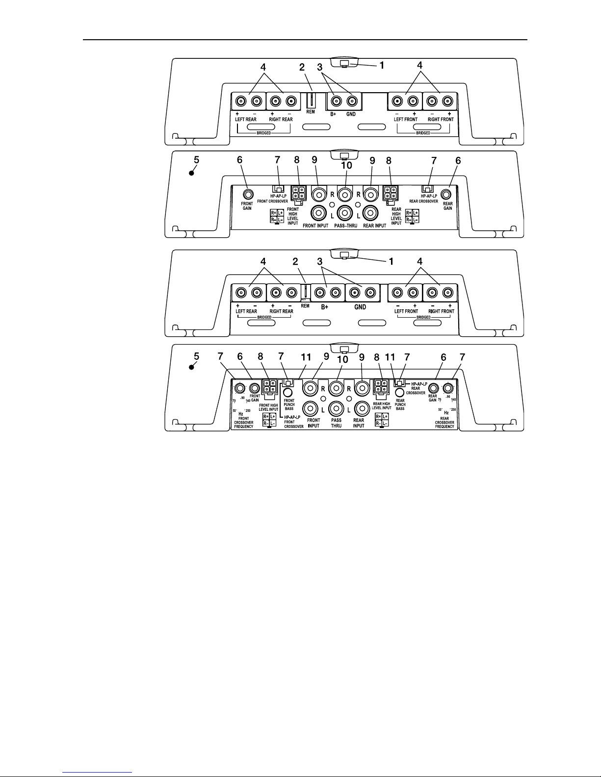
DESIGN FEATURES
1. LED Power Indicator (Top of unit) – The LED illuminates when the unit is turned on.
2. REM Terminal – This spade terminal is used to remotely turn-on and turn-off the amplifier when
+12V DC is applied.
3. Power Terminals – The power and ground connectors on the amplifier are platinum-plated and
will accommodate up to 8 AWG wire maximizing the input current capability of the amplifier.
4. Speaker Terminals – The heavy duty, platinum-plated terminal block connectors (+ and –) will
accept wire sizes from 8 AWG to 18 AWG. These platinum-plated connectors are immune to
corrosion that can cause signal deterioration.
5. Cast Aluminum Heatsink – The cast aluminum heatsink of the Punch amplifier dissipates heat
generated by the amplifier's circuitry. The inherent advantage of casting provides a 30%
improvement of cooling over conventional extrusion heatsink designs.
6. Gain Control – The input gain control is preset to match the output of most source units. It can
be adjusted to match output levels from a variety of source units.
7.
Internal Crossover (Models 301X & 501X) – Is a built-in 24dB/octave Butterworth filter
selectable between 120Hz High-Pass (HP), All Pass (AP), or 80Hz Low-Pass (LP) operation.
7.
Variable Crossover (Model 801X) – Is a built-in 24dB/octave Butterworth filter selectable for
High-Pass (HP), All Pass (AP), or Low-Pass (LP) operation variable from 50Hz to 250Hz.
8. High Level Inputs – The high level inputs use a detachable connector terminated with 20 AWG
leads. These inputs should be used if the source unit has only speaker line (high level) outputs
and not RCA outputs.
Power
Connection
Models 301X
& 501X
Power
Connection
Model 801X
Connections
Models 301X
& 501X
Connections
Model 801X

5
DESIGN FEATURES
INSTALLATION
INSTALLATION CONSIDERATIONS
The following is a list of tools needed for installation:
Volt/Ohm Meter
Wire strippers
Wire crimpers
Wire cutters
#2 Phillips screwdriver
Battery post wrench
Hand held drill w/assorted bits
1/8" diameter heatshrink tubing
Assorted connectors
Adequate Length—Red Power Wire
Adequate Length—Remote Turn-on Wire
Adequate Length—Black Grounding Wire
This section focuses on some of the vehicle considerations for installing your new amplifier.
Pre-planning your system layout and best wiring routes will save installation time. When deciding
on the layout of your new system, be sure that each component will be easily accessible for making
adjustments.
CAUTION: If you feel unsure about installing this system yourself, have it installed
by a qualified technician.
CAUTION: Before installation, disconnect the battery negative (-) terminal to
prevent damage to the unit, fire and/or possible injury.
Before beginning any installation, follow these simple rules:
1. Be sure to carefully read and understand the instructions before attempting to install the Unit.
2. For safety, disconnect the negative lead from the battery prior to beginning the installation.
3. For easier assembly, we suggest you run all wires prior to mounting your unit in place.
4. Route all of the RCA cables close together and away from any high current wires.
5. Use high quality connectors for a reliable installation and to minimize signal or power loss.
6. Think before you drill! Be careful not to cut or drill into gas tanks, fuel lines, brake or hydraulic
lines, vacuum lines or electrical wiring when working on any vehicle.
7. Never run wires underneath the vehicle. Running the wires inside the vehicle provides the best
protection.
8. Avoid running wires over or through sharp edges. Use rubber or plastic grommets to protect any
wires routed through metal, especially the firewall.
9. ALWAYS protect the battery and electrical system from damage with proper fusing. Install the
appropriate fuse holder and fuse on the +12V power wire within 18” (45.7 cm) of the battery
terminal.
10. When grounding to the chassis of the vehicle, scrape all paint from the metal to ensure a good,
clean ground connection. Grounding connections should be as short as possible and always be
connected to metal that is welded to the main body, or chassis, of the vehicle.
!
!
9. RCA Input Jacks – The industry standard RCA jacks provide an easy connection for signal level
input. They are platinum-plated to resist the signal degradation caused by corrosion.
10.
RCA Pass-Thru Jacks – The Pass-Thru provides a convenient source for daisy-chaining an
additional amplifier without running an extra set of RCA cables from the front of the vehicle to
the rear amplifier location.
11. Punch Bass (Model 801X) – The Punch Bass control helps correct for acoustical deficiencies in
the listening environment by helping produce full range sound without adding excessive boost.
The Punch Bass control is a narrow band adjustment at 45Hz variable from 0dB to + 18dB.
 Loading...