

Rockford Fosgate punch 120, punch 160, punch 250, punch 800, punch 360 Installation & Operation Manual
...
® ®
car audio
fanatics
for
punch
®
2-CHANNEL AMPLIFIER
INSTALLATION & OPERATION
2 - c h a n n e l
2 - c h a n n e l
2 - c h a n n e l
2 - c h a n n e l
2 - c h a n n e l
2 - c h a n n e l

PUNCH 120 PUNCH 160 PUNCH 250 PUNCH 360 PUNCH 500 PUNCH 800
Dynamic Power Rating
(IHF-202 Standard) - Measured at 14.4 Volts
Mono into a 4Ω Load
200 Watts x 1 236 Watts x 1 320 Watts x 1 450 Watts x 1 710 Watts x 1 960 Watts x
1
Per channel into a 2Ω Load
94 Watts x 2 113 Watts x 2 160 Watts x 2 210 Watts x 2 330 Watts x 2 480 Watts x 2
Per channel into a 4Ω Load
64 Watts x 2 77 Watts x 2 100 Watts x 2 140 Watts x 2 210 Watts x 2 240 Watts x 2
Continuous Power Rating
(Competition Standard) - Measured at 13.8 Battery Volts
RMS continuous power per channel,
30 Watts x 2 40 Watts x 2 62.5 Watts x 2 90 Watts x 2 125 Watts x 2 200 Watts x 2
both channels driven into a 4Ω load
from 20 to 20,000 Hz with less than
0.05% Total Harmonic Distortion (THD)
RMS continuous power per channel,
60 Watts x 2 80 Watts x 2 125 Watts x 2 180 Watts x 2 250 Watts x 2 400 Watts x 2
both channels driven into a 2Ω load
from 20 to 20,000 Hz, with less than
0.1% Total Harmonic Distortion (THD)
RMS continuous power mono into a
120 Watts x 1 160 Watts x 1 250 Watts x 1 360 Watts x 1 500 Watts x 1 800 Watts x 1
4Ω load from 20 to 20,000 Hz, with
less than 0.1% Total Harmonic Distortion (THD)
Signal-to-Noise Ratio (A-weighted) > 100dB > 100dB > 100dB > 100dB > 100dB > 100dB
Crossover Slope (Butterworth) 12dB/octave 12dB/octave 12dB/octave 12dB/octave 12dB/octave 12dB/octave
Crossover Frequency
80Hz 80Hz 50Hz – 210Hz 50Hz – 210Hz 50Hz – 210Hz 50Hz – 210Hz
Specifications are subject to change without notice.
– i –
S
PECIFICATIONS

PUNCH 120 PUNCH 160 PUNCH 250 PUNCH 360 PUNCH 500 PUNCH 800
Dimensions (end caps installed)
2.62" (6.65cm) H 2.62" (6.65cm) H 2.62" (6.65cm) H 2.62" (6.65cm) H 2.62" (6.65cm) H 2.62" (6.65cm) H
9.60" (24.38cm) W 9.60" (24.38cm) W 9.60" (24.38cm) W 9.60" (24.38cm) W 9.60" (24.38cm) W 9.60" (24.38cm) W
10.27" (26.08cm) L 10.27" (26.08cm) L 11.27" (28.62cm) L 12.27" (31.16cm) L 13.27" (33.70cm) L 18.27" (46.40cm) L
Heatsink Tpye (internal use only) #1 #1 #2 #3 #4 #6
Frequency Response (±0.5dB) 20Hz - 20kHz 20Hz - 20kHz 20Hz - 20kHz 20Hz - 20kHz 20Hz - 20kHz 20Hz - 20kHz
Bandwidth (±3dB) 10Hz - 200kHz 10Hz - 200kHz 10Hz - 200kHz 10Hz - 200kHz 10Hz - 200kHz 10Hz - 200kHz
Damping Factor @ 4Ω (at output connector) >200 >200 >200 >200 >200 >200
Slew Rate 30 Volts µs 30 Volts µs 30 Volts µs 30 Volts µs 30 Volts µs 30 Volts µs
IM Distortion (IHF) <0.05% <0.05% <0.05% <0.05% <0.05% <0.05%
Source Unit Compatibility (+15dB gain overlap)
17V max. (RCA) 17V max. (RCA) 17V max. (RCA) 17V max. (RCA) 17V max. (RCA) 17V max. (RCA)
Input Sensitivity (+0dB gain overlap) 250mV~4V (RCA) 250mV~4V (RCA) 250mV~4V (RCA) 250mV~4V (RCA) 250mV~4V (RCA) 250mV~4V (RCA)
650mV~11V (hi-level) 650mV~11V (hi-level) 650mV~11V (hi-level) 650mV~11V (hi-level) 650mV~11V (hi-level) 650mV~11V (hi-level)
Protection NOMAD - Internal analog-computer output protection circuitry limits power in case of
overload. Thermal switch shuts down the amplifier in case of overheating.
Battery Fuse Rating (External to Amplifier) 20A 20A 30A 40A 50A 60A*
Fuse Type ATC ATC ATC ATC AGU AGU
Equalization (45Hz Punch Bass) Adjustable Variable Variable Variable Variable Variable
(0,+6,+12dB) (0 to +18dB) (0 to +18dB) (0 to +18dB) (0 to +18dB) (0 to +18dB)
Input Impedance 20k ohms 20k ohms 20k ohms 20k ohms 20k ohms 20k ohms
*recommended fuse not supplied
Specifications are subject to change without notice.
S
PECIFICATIONS
– ii –

Dear Customer,
Congratulations on your purchase of the world's finest brand of car audio amplifiers.
At Rockford Fosgate we are fanatics about musical reproduction at its best, and we are
pleased you chose our product. Through years of engineering expertise, hand craftsmanship and critical testing procedures, we have created a wide range of products that
reproduce music with all the clarity and richness you deserve.
For maximum performance we recommend you have your new Rockford Fosgate
product installed by an Authorized Rockford Fosgate Dealer, as we provide specialized
training through Rockford Technical Training Institute (RTTI). Please read your
warranty and retain your receipt and original carton for possible future use.
Great product and competent installations are only a piece of the puzzle when it comes
to your system. Make sure that your installer is using 100% authentic installation
accessories from Connecting Punch in your installation. Connecting Punch has
everything from RCA cables and speaker wire to Power line and battery connectors.
Insist on it! After all, your new system deserves nothing but the best.
To add the finishing touch to your new Rockford Fosgate image order your Rockford
wearables, which include everything from T-shirts and jackets to hats and sunglasses.
To get a free brochure on Rockford Fosgate products and Rockford accessories, in the
U.S. call 480-967-3565 or FAX 480-967-8132. For all other countries, call +001-480967-3565 or FAX +001-480-967-8132.
If, after reading your manual, you still have questions regarding this product,
we recommend that you see your Rockford Fosgate dealer. If you need further
assistance, you can call us direct at 1-800-669-9899. Be sure to have your serial
number, model number and date of purchase available when you call.
PRACTICE SAFE SOUND™
CONTINUOUS EXPOSURE TO SOUND PRESSURE LEVELS OVER 100dB
MAY
CAUSE PERMANENT HEARING LOSS. HIGH POWERED AUTOSOUND
SYSTEMS
MAY PRODUCE SOUND PRESSURE LEVELS WELL OVER
130dB. USE COMMON SENSE AND PRACTICE SAFE SOUND.
The serial number can be found on the outside of the box. Please record it in
the space provided below as your permanent record. This will serve as
verification of your factory warranty and may become useful in recovering your
amplifier if it is ever stolen.
Serial Number: ________________________________
Model Number: ________________________________

T
ABLE OF
C
ONTENTS
Specifications .............................................................................................. i
Introduction................................................................................................ 1
Punch Amplifier Accessory Pack ................................................................... 1
2-Channel Feature Chart .............................................................................. 2
Design Features .......................................................................................... 3
Installation Considerations ........................................................................... 6
Mounting Location ...................................................................................... 7
Battery and Charging .................................................................................. 8
Wiring the System ....................................................................................... 8
Using Passive Crossovers ........................................................................... 10
Table of Component Values........................................................................ 11
Installation ............................................................................................... 12
Operation................................................................................................. 19
System Diagrams...................................................................................... 20
Troubleshooting ........................................................................................ 23
Dynamic Power Measurements................................................................... 25
Warranty Information ................................................................................ 27
International Information ............................................................................ 28
Sections marked
ADVANCED OPERATION
include in-depth
technical information
Sections marked
TROUBLESHOOTING
include recommendations for
curing installation problems
Sections marked
INSTALLATION
include “slam dunk”
wiring connections
Welcome to Rockford Fosgate! This manual is designed to provide information
for the owner, salesperson and installer. For those of you who want quick
information on how to install this product, please turn to the
Installation
Section
of this manual or refer to the icons listed below. Other information can
be located by using the Table of Contents. We, at Rockford Fosgate, have
worked very hard to make sure all the information in this manual is current. But,
as we are constantly finding new ways to improve our product, this information
is subject to change without notice.
GETTING STARTED
a
d
v
a
n
c
e
d
O
p
e
r
a
t
i
o
n
+
I
N
S
T
A
L
L
A
T
I
O
N
+ -
+ -
TROUBLE-
S
H
O
O
T
I
N
G
?

I
NTRODUCTION
Rockford engineers designed the Punch 2-channel amplifiers to withstand
the rugged automotive environment while delivering superior sound quality
in a flexible, reliable, and efficient package. TRANS•ANA is a low voltage
circuit in the preamp stage of all Punch amplifiers that lets the music sound
crystal clear and very real, even when played at high volume levels. This is
matched with TOPAZ, a unique grounding circuit used to eliminate noise
problems associated with car audio systems and their installation. Flexibility
is accomplished with the use of a built-in crossover. The use of a protection
circuit called NOMAD, along with MOSFET and DSM (Discrete Surface
Mount) technologies improve amplifier efficiency. The result of these
components give the Punch amplifier awesome sound quality in a “Bullet
Proof” package. An explanation of these technologies, most of which are
exclusively designed and patented by Rockford, are described in the
Technical Design Features.
– 1 –
P
UNCH
A
MPLIFIER
A
CCESSORY
P
ACK
The accessory pack shipped with the Punch 2-channel amplifiers includes
the mounting hardware necessary to secure the amp to the vehicle and to
attach the end caps to the amplifier.
Installation & Operation Manual
Punch Verification Certificate
(4) Amplifier mounting screws (#8 x 3/4" Phillips)
(1) ATC Inline Fuseholder (Punch 120, 160, 250, 360)
(1) AGU Inline Fuseholder (Punch 500)
(1) ATC 15 Amp Fuse (Punch 120)
(1) ATC 20 Amp Fuse (Punch 160)
(1) ATC 30 Amp Fuse (Punch 250)
(1) ATC 40 Amp Fuse (Punch 360)
(1) AGU 50 Amp Fuse (Punch 500)
Note:
Refer to the Specification section of this manual for recommended
Punch 800 fuse size.

– 2 –
P
UNCH
2-C
HANNEL
A
MPLIFIER FEATURE
C
HART
PUNCH AMPLIFIER MODEL
120 160 250 360 500 800
# of CHANNELS 22 2 222
Stable into: (stereo/bridged) 2Ω/4Ω 2Ω/4Ω 2Ω/4Ω 2Ω/4Ω 2Ω/4Ω 2Ω/4Ω
CIRCUITRY
1
TRANS•
ana
– circuit topology xx x xxx
TRANS•
nova
– patented circuit topology
2
–– – –––
Class-G
– high efficiency topology –– – –––
MEHSA
– heat dissipating technology xx x xxx
TOPAZ
– patented noise eliminating circuitry
3
xx x xxx
DSM
– discrete surface mount xx x xxx
MOSFETs
– power supply & output devices xx x xxx
NOMAD
– protection circuit xx x xxx
FEATURES
Die Cast Heatsink
4
xx x xxx
Hi-Level Inputs
– for factory radios xx x xxx
RCA Inputs
– for aftermarket radios xx x xxx
Balanced Inputs – – – – – –
Input Switches – eliminates “Y” adaptors –– – –––
Pass-Thru
– feeds signal to aux. amp –– – –––
Pwr/Spk Screw Terminals x x – – – –
Pwr/Spk Block Terminals – – x x x x
4 Gauge Pwr/Gnd – – – – – –
Adjustable Punch Bass
(0dB/+6dB/+12dB @ 45Hz)
x– – –––
Variable Punch Bass
(0dB ~+18dB @ 45Hz) –x x xxx
Adjustable Xover
(120Hz HP / 80Hz LP)
HP/FULL/LP5 HP/FULL/LP
5
––––
Variable Xover (50Hz ~ 210Hz) –– HP/FULL/LP
5
HP/FULL/LP5 HP/FULL/LP
5
HP/FULL/LP
5
Crossover Slope (Butterworth) 12dB 12dB 12dB 12dB 12dB 12dB
Phase Warp
(00 ~ 180
0
) -- - ---
1
Additional information on features, specifications and system designs can be found at: www.rockfordfosgate.com
2
Trans•nova is patented under "U.S. Patent No. 4,467,288"
3
TOPAZ is patented under "U.S. Patent No. 5,751,823"
4
Diecast Heatsink is patented under "U.S. Patent No. D401,225"
5
HP = 12dB/octave High-Pass / LP = 12dB/octave Low-Pass / FULL = Full Range
6
Recommended fuse not supplied with amplifier
– 3 –
D
ESIGN
F
EATURES
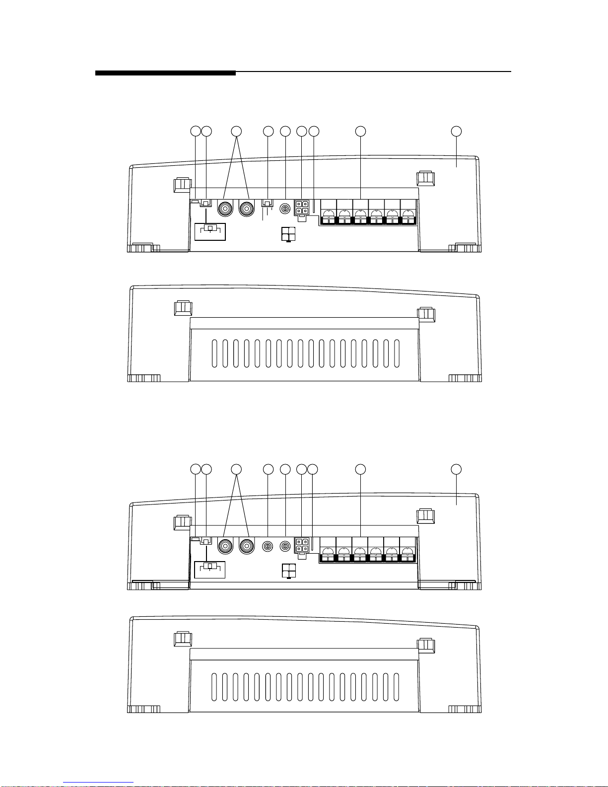
L+
L–
R+
R–
+ –
B+ GND
Left Right
+ –
120HP-Full-80LP
Crossover
REM
High
Level
Input
LED
Left Input Right Input
Gain
+12dB
+6dB
0dB
Punch
Bass
4
2
7 5
3
6
8
9
1
4
2
3
6
7
8
REM
+ –
B+ GND
High
Level
Input
LED
Left Input Right Input
Gain
Left Right
Punch
Bass
+ –
120HP-Full-80LP
Crossover
L+
L–
R+
R–
L+
L–
R+
R–
5
9
1
Punch 120
2-channel
Punch 160
2-channel
– 4 –
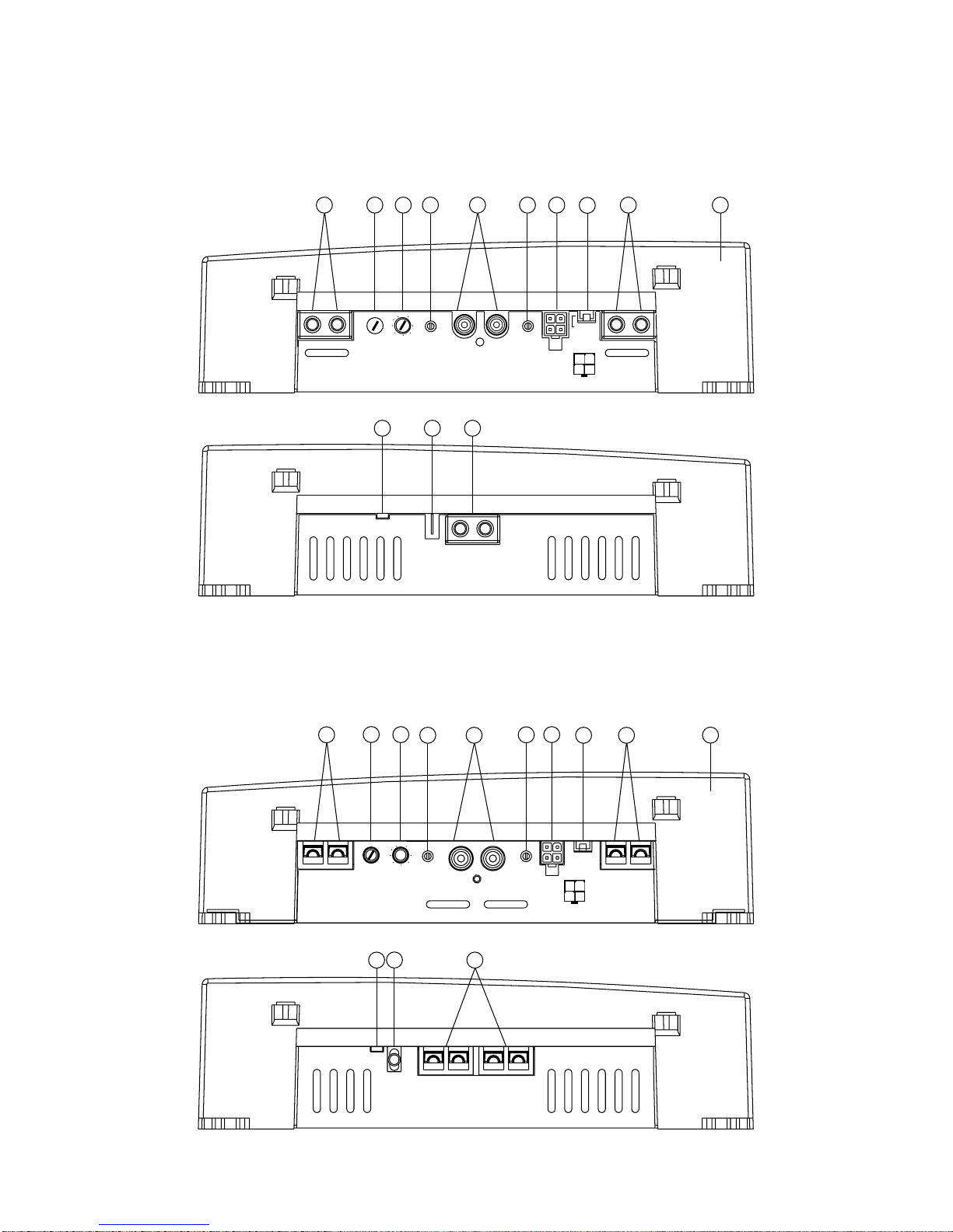
65
80
55
50
110
210
Hz
145
190
Speaker
+ L –
L+
L–
R+
R–
2
8
2
1
9
3
2
7 8
6
4
6 5
REM
B+ GND
LED
HP–Full–LP
Crossover
Right
Gain
Right
Input
Left
Input
Left
Gain
Crossover
Frequency
Punch
Bass
High
Level
Input
Speaker
+ R –
HP–Full–LP
Crossover
High
Level
Input
Right
Gain
Right
Input
Left
Input
Left
Gain
Crossover
Frequency
Punch
Bass
Speaker
+ L –
Speaker
+ R –
L+
L–
R+
R–
65
80
55
50
110
210
Hz
145
190
REM
B+
GND
LED
9
2
2
7
4
5
2
1
3
8
6
6
8
Punch 800
2-channel
Punch 250
2-channel
Punch 360
2-channel
Punch 500
2-channel

– 5 –
1. Cast Aluminum Heatsink – The cast aluminum heatsink of the Punch
amplifier dissipates heat generated by the amplifier's circuitry. The
inherent advantage of casting provides a 30% improvement of cooling
over conventional extrusion heatsink designs.
2. Speaker/Power Terminals – These gold-plated connectors are used for
the connection of speaker and power wire and are immune to corrosion
that can cause signal degradation. The Punch 120 and Punch 160
utilize a barrier strip that will accept #10 spade lugs or bare speaker and
power wires sized from 10-18 AWG. The Punch 250, Punch 360,
Punch 500, and Punch 800 utilize heavy duty terminal block connectors that will accept bare wires size from 8-18AWG.
3. REM Terminal – This spade terminal is used to remotely turn-on and
turn-off the amplifier when +12V DC is applied.
4. RCA Input Jacks – The industry standard RCA jack provides an easy
connection for signal level input. They are gold-plated to resist the signal
degradation caused by corrosion.
5. High Level Inputs – The high level inputs use a detachable connector
terminated with 20 AWG leads. These inputs should be used if the source
unit has only speaker line (high level) outputs and not RCA outputs.
6. Gain Control – The input gain control is preset to match the output of
most source units. They can be adjusted to match output levels from a
variety of source units.
7. Punch Bass – The Punch Bass helps correct for acoustical deficiencies
in the listening environment. The Punch Bass allows a narrow band
adjustment at 45Hz to help reproduce full range sound without excessive
boost. The Punch 120 utilizes a switch that is adjustable at 0dB/+6dB/
+12dB increments. The Punch 160, Punch 250, Punch 360, Punch
500, and Punch 800 utilize a control that is variable from 0dB to
+18dB.
8. Internal Crossover – The internal crossover is used to delegate a specific
range of frequencies to the speaker system for optimum performance.
The crossover can perform three functions: High-Pass (HP), Low-Pass
(LP), or Full Range (FULL). The Punch 120 and Punch 160 utilize a
12dB/octave Butterworth crossover fixed at 120Hz HP and 80Hz LP.
The Punch 250, Punch 360, Punch 500, and Punch 800 utilize a
12dB/octave Butterworth crossover variable from 50Hz to 210Hz.
9. LED Power Indicator – The LED illuminates when the unit is turned on.

I
NSTALLATION
C
ONSIDERATIONS
The following is a list of tools you will need for installing the Punch amplifier:
Allen wrenches 9/64" & 3/32" (included) Voltmeter
Wire strippers Battery post wrench
Electric hand drill w/assorted bits Wire cutters
17' (518.16cm) Red Power Wire Assorted connectors
12' (365.76cm) Remote Turn-On Wire Wire crimpers
1.5' (45.72cm) Black Grounding Wire
– 6 –
This section focuses on some of the vehicle considerations for installing your
new Punch amplifier. Checking your battery and present sound system, as
well as pre-planning your system layout and best wiring routes will save
installation time. When deciding how to lay out your new system, be sure that
each component will be easily accessible for making adjustments.
Before beginning any installation, be sure to follow these simple rules:
1. Be sure to carefully read and understand the instructions before attempting to install the amplifier.
2. For safety, disconnect the negative lead from the battery prior to
beginning the installation.
3. For easier assembly, we suggest you run all wires prior to mounting your
amplifier in place.
4. Route all of the RCA cables close together and away from any high
current wires.
5. Use high quality connectors for a reliable installation and to minimize
signal or power loss.
6. Think before you drill! Be careful not to cut or drill into gas tanks, fuel
lines, brake or hydraulic lines, vacuum lines or electrical wiring when
working on any vehicle.
7. Never run wires underneath the vehicle. Running the wires inside the
vehicle provides the best protection.
8. Avoid running wires over or through sharp edges. Use rubber or plastic
grommets to protect any wires routed through metal, especially the
firewall.
9. ALWAYS protect the battery and electrical system from damage with
proper fusing. Install a fuseholder and appropriate fuse on the +12V
power wire within 18” (45.7 cm) of the battery terminal.
10. When grounding to the chassis of the vehicle, scrape all paint from the
metal to ensure a good, clean ground connection. Grounding connections should be as short as possible and always be connected to metal
that is welded to the main body, or chassis, of the vehicle.

M
OUNTING
L
OCATION
The mounting location and position of your amplifier will have a great effect
on its ability to dissipate the heat generated during normal operation. The
design of our cast aluminum heatsink serves to easily dissipate the heat
generated over a wide range of operating conditions. However, to maximize
the performance of your amplifier, care should be taken to ensure adequate
ventilation.
Trunk Mounting
Mounting the amplifier vertically on a surface with the fin grooves running
up and down will provide the best cooling of the amplifier.
Mounting the amplifier on the floor of the trunk will work but provides less
cooling capability than vertical mounting.
Mounting the amplifier upside down to the rear deck of the trunk will not
provide proper cooling and will severely affect the performance of the
amplifier and is strongly
not
recommended.
Passenger Compartment Mounting
Mounting the amplifier in the passenger compartment will work as long as
you provide a sufficient amount of air for the amplifier to cool itself. If you
are going to mount the amplifier under the seat of the vehicle, you must have
at least 1" (2.54cm) of air gap around the amplifier's heatsink.
Mounting the amplifier with less than 1" (2.54cm) of air gap around the
amplifier's heatsink in the passenger compartment will not provide proper
cooling and will severely affect the performance of the amplifier and is
strongly
not
recommended.
Engine Compartment Mounting
Rockford Fosgate amplifiers should
never
be mounted in the engine
compartment. Not only will this void your warranty but could create an
embarrassing situation caused by the ridicule from your friends.
– 7 –

B
ATTERY AND
C
HARGING
Amplifiers will put an increased load on the vehicle's battery and charging
system. We recommend checking your alternator and battery condition to
ensure that the electrical system has enough capacity to handle the
increased load of your stereo system. Stock electrical systems which are in
good condition should be able to handle the extra load of any Rockford
amplifier without problems, although battery and alternator life can be
reduced slightly. To maximize the performance of your Rockford Fosgate
amplifier, we suggest the use of a heavy duty battery and an energy storage
capacitor.
W
IRING THE
S
YSTEM
CAUTION:
Avoid running power wires near the low level input cables,
antenna, power leads, sensitive equipment or harnesses. The power
wires carry substantial current and could induce noise into the audio
system.
• For safety, disconnect the negative lead from the battery prior to beginning
the installation.
1. Plan the wire routing. Take care when running signal level RCA cables
to keep them close together but isolated from the amplifier's power cables
and any high power auto accessories, especially electric motors. This is
done to prevent coupling the noise from radiated electrical fields into the
audio signal. When feeding the wires through the firewall or any metal
barrier, protect them with plastic or rubber grommets to prevent short
circuits. Leave the wires long at this point to adjust for a precise fit at a
later time.
2. Prepare the Power cable for attachment to the amplifier by stripping 1/
2" of insulation from the end of the wire. Insert the bared wire into the B+
terminal and tighten the set screw to secure the cable in place.
NOTE: The B+ cable MUST be fused 18" or less from the vehicle's
battery. Install the fuseholder under the hood and prepare the cable
ends as stated above. Connections should be
water tight.
Trim the power cable within 18" of the battery and
strip 1/2" of insulation from the end of the wire. Cut
the wire loop that is attached to the fuseholder in
half and splice the fuse into the power line using
appropriate inline connectors. Use the section of
cable that was trimmed earlier and connect it to the
other end of the fuseholder.
Cut
here
X
– 8 –
 Loading...