

Rockford Fosgate Punch, Punch 4040DSM, Punch 4080DSM Owner's Manual

1
8
DSM
4-CHANNEL AMPLIFIER
OWNER’S MANUAL

Dear Customer,
Congratulations on your purchase of the world’s finest brand of car audio
amplifiers. At Rockford Fosgate we are committed to musical reproduction at
its best, and we are pleased you chose our product. Through years of engineering expertise, hand craftsmanship and critical testing procedures, we have
created a wide range of products that reproduce music with all the clarity and
richness you deserve.
For maximum performance we recommend you have your new Rockford
Fosgate product installed by an Authorized Rockford Fosgate Dealer, as we
provide specialized training through Rockford Technical Training Institute
(RTTI).
Please read your warranty and retain your receipt and original carton
for possible future use
.
To add the finishing touch to your new Rockford Fosgate image, order your
Rockford accessories, which include everything from T-shirts and jackets to
hats and sunglasses.
To get a free brochure on Rockford
Fosgate products and Rockford accessories,
please call 602-967-3565 or FAX 602-967-8132. For Canada, call Korbon
Trading at 416-567- 1920. For International orders, FAX +00l- 1-602-967-
8132 or call +001-l-602-967-3565.
PRACTICE SAFE
SOUND™
CONTINUOUS EXPOSURE TO SOUND PRESSURE LEVELS OVER
1OOdB
MAY CAUSE PERMANENT HEARING LOSS. HIGH POWERED
AUTOSOUND SYSTEMS MAY PRODUCE SOUND PRESSURE LEVELS
WELL OVER 130dB. USE COMMON SENSE AND PRACTICE SAFE
SOUND.
The
serial
number can be found on the outside of the box.
Please record it in
the space provided below
as your permanent record. This will become useful
in recovering
your amplifier if it is ever stolen and serve as verification of your
factory warranty.
Serial Number:
Model Number:

TABLE OF CONTENTS
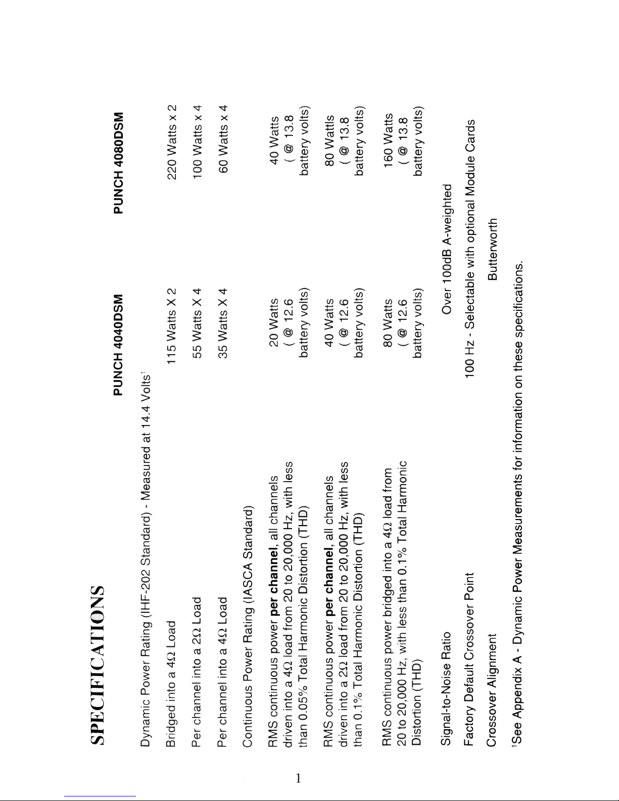
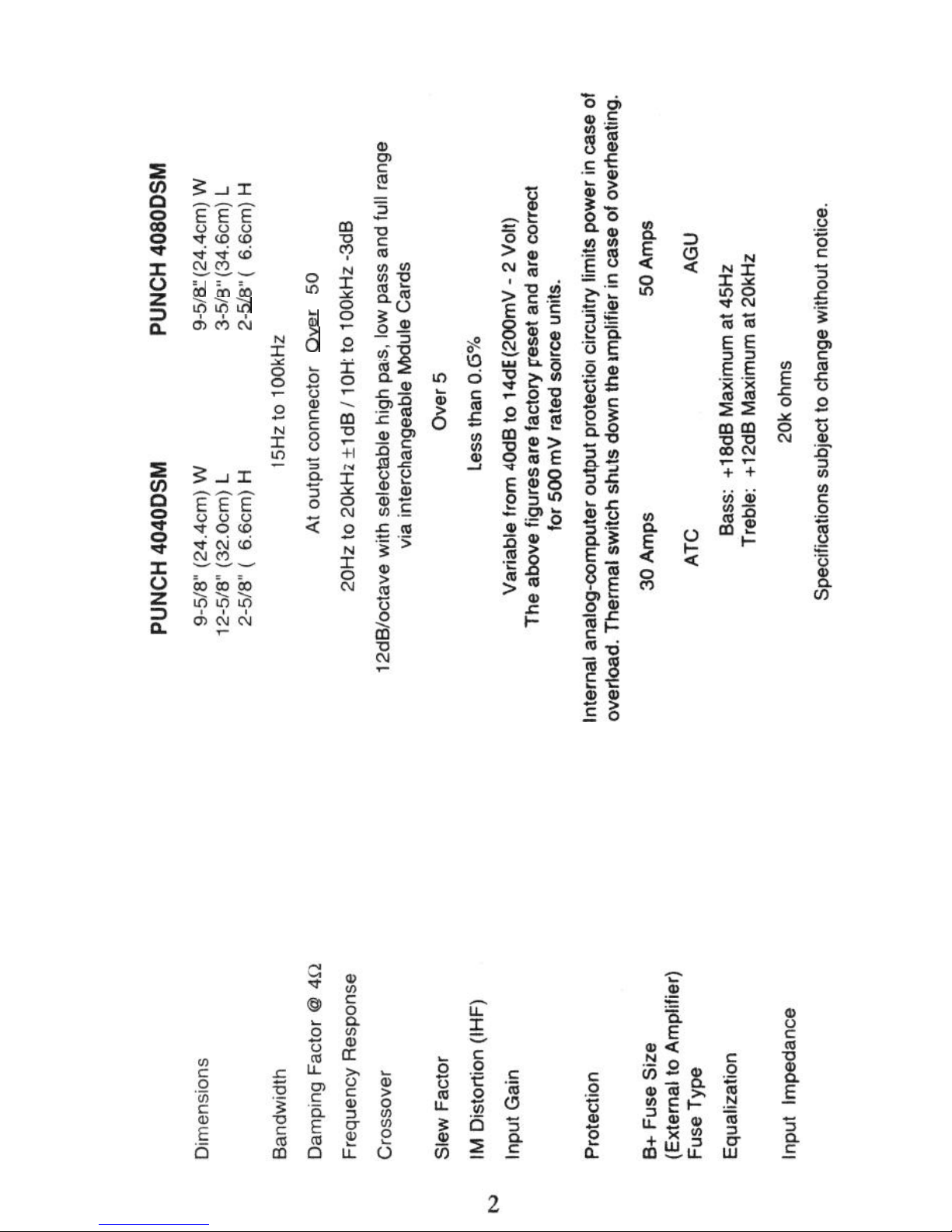
Specifications ....................................................................................
1
Punch 4-Channel Accessory Pack ...................................................
3
Introduction .......................................................................................
4
Features and
Benefits
.................................................................
4
Controls
and Features......................................................................
5
Top View of Amplifier and End Caps.. .........................................
5
Power/REM/LED Side .................................................................
6
Input/Output
Terminal Side .........................................................
7
Installation
Considerations
...............................................................
8
Tools Needed ............................................................................... 9
Battery and Charging ........................................................................
9
Mounting and Location.. ................................................................. 10
Trunk Mounting ..........................................................................
10
Passenger Compartment Mounting
...........................................
10
Wiring the Punch .....................................................................................
10
Preparing Wires and Fuses .............................................................
10
Wiring the Fuse Holder ..............................................................
10
Wiring the Ring and Spade Connectors .....................................
12
Power ......................................................................................... 12
Ground .......................................................................................
13
Remote Turn-on ........................................................................
13
Input ...........................................................................................
13
Speakers ....................................................................................
14
Bridged/Mono
Configuration .....................................................
14
Passive Crossover Impedance ................................................
14
Table
of
Component
Values..
.........................................................
16
Active Crossover Mode Selection
...................................................
17
Crossover Frequency Settings .......................................................
17
Wiring Diagrams ...........................................................................
18
Troubleshooting
............................................................................
25
Dynamic Power Measurements .....................................................
28
Warranty Information......................................................................
31
=w =w =w
hi3G-i
hcb&
5:
t
6
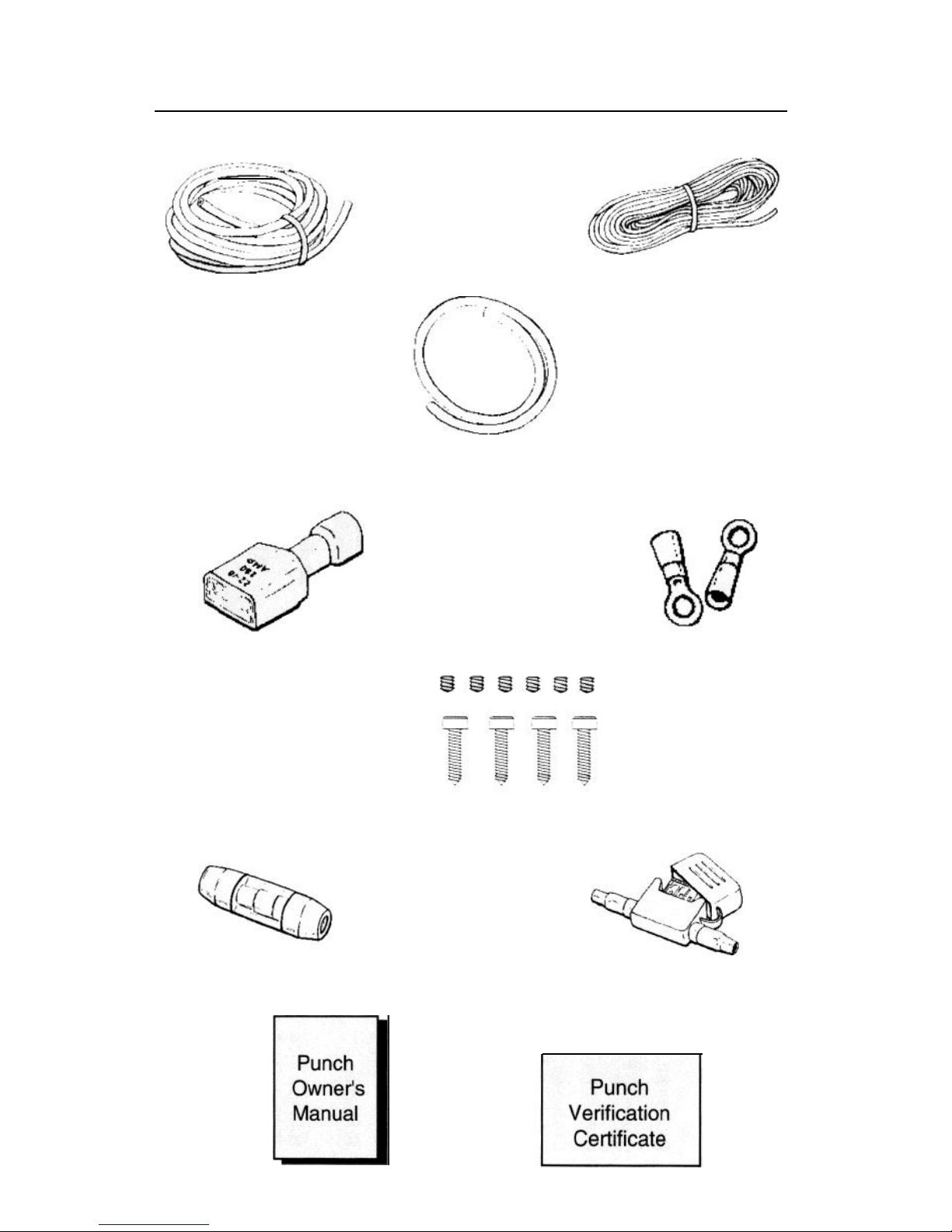
PUNCH 4-CHANNEL ACCESSORY PACK
17’ (518cm)
Red Power
Wire
Remote Turn-on Wire
Connector Plug
Fuse Holder 4080
Punch
(366cm)
Blue‘
Remote
Turn-on Wire
1.5’ (46cm) Black
Grounding Wire
Power Ring
1SB9SG
Terminals
Allen Head Set Screws
and Mounting Screws
Fuse Holder 4040
3

INTRODUCTION
Features
and
Benefits
This manual provides information on the features, instal-
lation, and operation of the Punch 4040 DSM and 4080
DSM Amplifiers. We suggest you save this manual for
future reference.
We strongly recommend you have your Authorized Rock-
ford Fosgate Dealer install your new Punch 4-channel
amplifier. If you do choose to install the amplifier yourself,
please be sure to read the entire manual before beginning.
The Rockford Fosgate 4-Channel automotive stereo power
amplifiers provide state-of-the-art sound in cars, vans,
boats, or wherever a high current
12
volt power source is
available.
“Discrete Surface Mount” (DSM)
technology is utilized
in the crafting of all of our Punch amplifiers. This process
provides greater ruggedness and consistency of both
components and layout. Already used heavily in aerospace and industrial applications, this technology is also
highly advantageous in the hostile automotive environment.
Low Level Input Senstivity.
The Punch 4-channel ad-
justable input circuits are designed to match almost any
music source. The amplifiers will drive most normal
speaker types.
Punch Equalization.
This circuit is designed to compensate for the acoustic inadequacies of the automotive
environment. This patented circuitry will correct for the
poor bass response and natural high frequency roll-off
inherent in the world of automotive stereo. The result is
full-range sound without the unpleasant changes in the
mid-range sound produced by most tone control and
equalizer circuits.
Active Electronic Crossover Modules
built-into the
4040 and 4080 features 12 dB/octave Butterworth filters.
The independent crossover points in these plug-in modules allow for various configuration possibilities.
4
Real Time Power Protection (RT.P.P.) allows
for the
greatest power output under all load conditions. When
output reaches an unsafe level it will be reduced, unlike
current limiting which often causes premature protection
or failure to protect at all.
To get a better understanding of the Punch let’s take a
closer look.
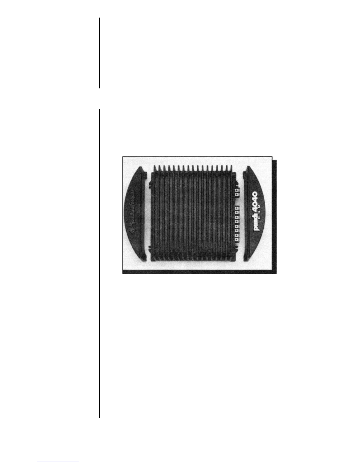
CONTROLS AND FEATURES
Punch
4-Channel
Housing
End Caps
This section describes the various controlsand features of
the Punch 4040 DSM and 4080 DSM amplifiers.
Top View of Amplifier and End Caps
The cast aluminum
heatsink
of the Punch 4-Channel is
designed for high performance cooling. The raised design
of the housing allows cables and wires to run underneath
the unit. This provides for greater wiring flexibility and
protects the cables from damage caused by excessive
heat and bending.
Interchangeable end caps conceal the wiring and input
cables, giving the amplifier a clean, “stealth” look.
Also
incorporated, is a holding dimple built into the end cap.
This small feature enables the cap to be held in place while
being mounted.
The end caps are secured to the housing with flush
mounting, captive screws.
5
Mounting
Four (4) custom, round, hex screws included in the acces-
Screws
sory pack hold the unit in place. These screws are covered
when the end caps are installed.
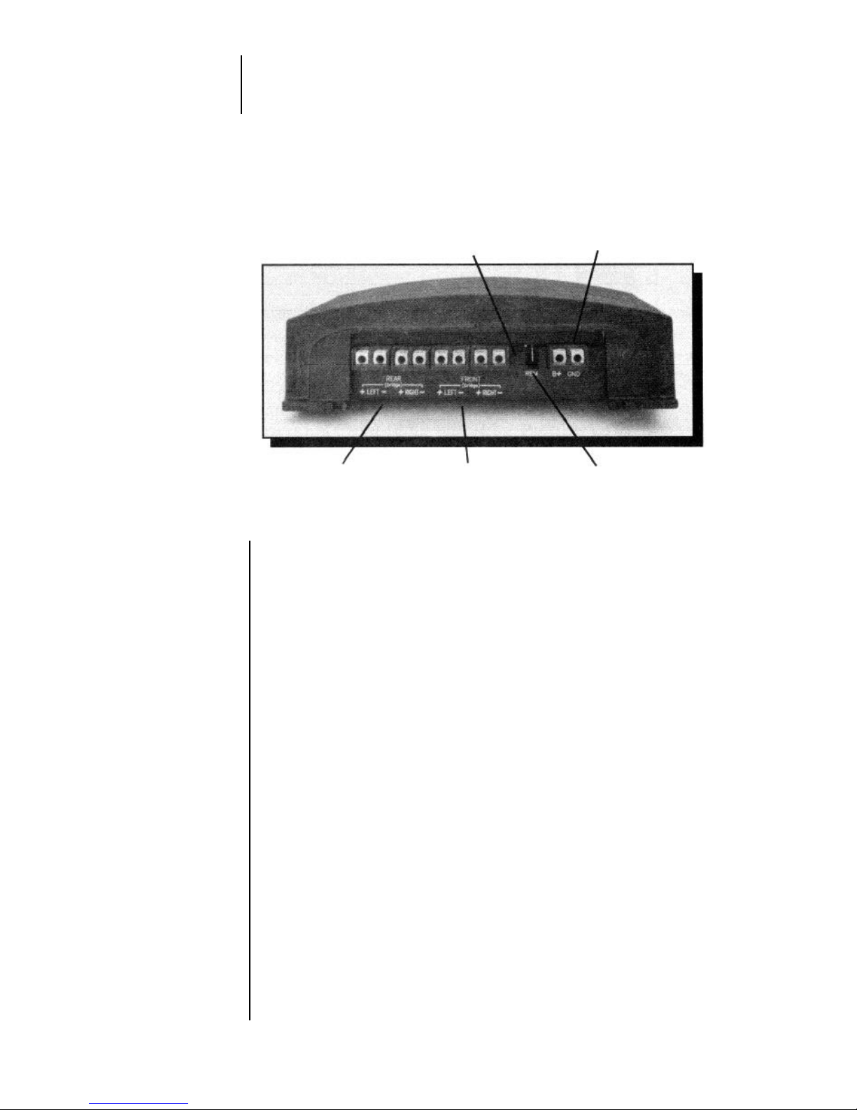
Power/REM/LED Side
LED
B+/GND
Indicator
Power Connectors
Rear Speaker
Output Terminals
Front Speaker
Output Terminals
REM
Connector
REM
Connector
LED Power
Indicator
B+/GND
Power
Connector
Speaker
Ouptut
Terminals
The Punch 4-Channel is turned on by connecting the blue
remote turn-on wire to the source unit’s “Accessory” or
“Auto Antenna” lead, either of which will go to +12 volts
when the source unit is turned on.
The LED illuminates when the unit is activated.
These connectors are used to supply power and ground
to the amplifier and accept 12 gauge
-
8 gauge wire.*
These gold-plated terminal blocks connect the Right/Left
Front and Right/Left Rear channel outputs to the speak-
ers and accept wire sizes from 8 gauge through 18 gauge.
Gold-plated connectors are immune to corrosion that can
cause signal deterioration.
*Rockford Fosgate’s Perfect Interface line of accessories in-
cludes high quality power
and speaker wire, gold plated RCA
interconnecting cable and other products to complete your
installation. Ask your Authorized Rockford Fosgate Dealerabout
Perfect Interface.
6
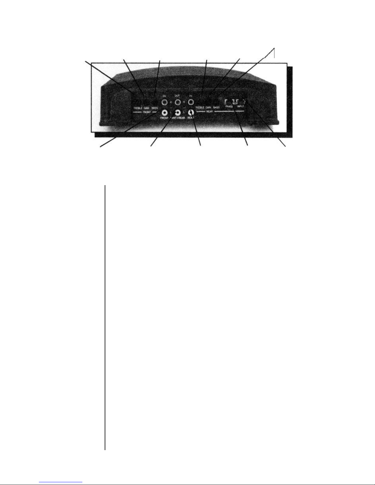
Input/Output Terminal Side
Front Treble Front Input Front Bass Rear Treble
Rear Input
Rear Bass
Adjustment Gain Adjustment Adjustment Gain Adjustment
Control Control Control Control Control
/
Control
Front Input Front+Rear Rear Input 0/180° Rear Front/Rear
Connectors Summed Pass-Thru Connectors Phase Selector
lnput Switch
Front/Rear
Input Switch
0/180° Rear
Phase
Selector
Switch
Treble/Bass
Input Gain
Controls
Connectors Switch ’
This switch allows you to use the front input to drive both
Front and Rear channels. Switching to Rear position
allows you to run separate Front and Rear inputs. This
eliminates the need for a “Y-adapter” when using the
amplifier in a bi-amplified or
4-Channel
mode.
This switch enables you to easily invert the phase of the
Rear channels on the amplifier without having to disconnect the speaker wires. See the wiring diagram on page
17 for use.
These controls adjust the amount of treble and bass
response desired. To increase the amount of response,
turn the controls clockwise; to decrease, turn the controls
counterclockwise. Note that there are separate Bass and
Treble controls for Front and Rear channels.
These controls are factory preset to 500 millivolts to
match most head units and are variable from 100 millivolts
to two volts. (More than likely they will not need
adjusting. )
If just a little volume from the source unit drives the
amplifier into distortion, reduce the input gain controls so
that the distortion doesn’t start until the source volume is
at about
3/4 of its rotation. Note that there are separate
Front and Rear gain controls.
7

Input
Connectors
Front & Rear
Summed
Pass-Thru
Connectors
The amplifier’s signal input, female, RCA jacks should be
connected to the source unit’s signal outputs with highquality RCA cables. The connectors have been plated in
gold to eliminate the possibility of corrosion that can cause
signal deterioration.
These pass-thru connectors allow you to daisy-chain an
additional Punch amplifier without running an additional
set of RCA cables from the front of the vehicle to the rear
amplifier location. The crossover module in the Pass-Thru
RCA circuit allows the daisy-chained amplifier to be con-
figured independently of the Front and Rear channels for
low pass, high pass or full range operation.
The Pass-Thru signal isderived by summing the Front Left
and Rear Left inputs to create the Left output, and summing the Front Right and Rear Right input to create the
Right output. This provides constant output regardless of
the source unit fade position.
INSTALLATION CONSIDERATIONS
This section focuses on some of the vehicle considerations for installing your new Punch 4-Channel amplifier.
Checking your battery and current sound system, as well
as pre-planning your system layout and best wiring routes
will save installation time. When deciding how to lay out
your new system, be sure that each component will be
easily accessible for making adjustments.
Before beginning any installation, be sure to follow these
simple rules:
1.
Carefully read and understand the instructions before
attempting to install the amplifier.
2.
For easier assembly, we suggest you run all wires
prior to mounting your amplifier in place.
3.
Use only quality connectors for making connections.
See your Authorized
Rockford
Fosgate Dealer for
Perfect interface wire enhancements.
8
 Loading...