

Page 1

®
PUNCH
STATUS
DISPLAY
PSD-1
INSTALLATION & OPERATION
®®
Page 2

Page 3

Dear Customer,
Congratulations on your purchase of the world's finest brand of car audio accessories.
At Rockford Fosgate we are committed to musical reproduction at its best, and we are
pleased you chose our product. Through years of engineering expertise, hand craftsmanship and critical testing procedures, we have created a wide range of products that
reproduce music with all the clarity and richness you deserve.
For maximum performance we recommend you have your new Rockford Fosgate
product installed by an Authorized Rockford Fosgate Dealer, as we provide specialized
training through Rockford Technical Training Institute (RTTI). Please read your
warranty and retain your receipt and original carton for possible future use.
To add the finishing touch to your new Rockford Fosgate image, order your Rockford
accessories, which include everything from T-shirts and jackets to hats and sunglasses.
To get a free brochure on Rockford Fosgate products and Rockford accessories, in the
U.S. call 602-967-3565 or FAX 602-967-8132. For all other countries, call +001602-967-3565 or FAX +001-602-967-8132.
PRACTICE SAFE SOUND™
CONTINUOUS EXPOSURE TO SOUND PRESSURE LEVELS
OVER 100dB MAY CAUSE PERMANENT HEARING LOSS. HIGH
POWERED AUTO SOUND SYSTEMS MAY PRODUCE SOUND
PRESSURE LEVELS WELL OVER 130dB. USE COMMON SENSE
AND PRACTICE SAFE SOUND.
If, after reading your manual, you still have questions regarding this product,
we recommend that you see your Rockford Fosgate dealer. If you need further
assistance, you can call us direct at 1-800-795-2385. Be sure to have your serial
number, model number and date of purchase available when you call.
The serial number can be found on the outside of the box. Please record it in
the space provided below as your permanent record. This will serve as
verification of your factory warranty and may become useful in recovering your
product if it is ever stolen.
Serial Number: ____________________
Model Number:____________________
Page 4

TABLE OF CONTENTS
Introduction ............................................................................................1
Accessory Pack .......................................................................................1
Design Features.......................................................................................2
Installation Considerations ......................................................................3
Mounting Locations ................................................................................4
Wiring the System ...................................................................................5
Installation ..............................................................................................6
System Diagrams...................................................................................10
Rockford Fosgate Accessories................................................................14
Troubleshooting ....................................................................................14
Specifications........................................................................................16
Warranty Information............................................................................17
International Information.......................................................................18
GETTING STARTED
Welcome to Rockford Fosgate! This manual is designed to provide
information for the owner, salesperson and installer. For those of you who
want quick information on how to install this product, please turn to the
Installation Section of this manual or refer to the icons listed below. Other
information can be located by using the Table of Contents. We, at
Rockford Fosgate, have worked very hard to make sure all the information
in this manual is current. But, as we are constantly finding new ways to
improve our product, this information is subject to change without notice.
I
® ®
N
S
T
A
L
L
A
T
I
O
N
Sections marked
INSTALLATION
include “slam dunk”
wiring connections
TROUBLE-
S
H
O
O
T
I
N
G
Sections marked
TROUBLESHOOTING
include recommendations
for curing
installation problems
Page 5

INTRODUCTION
The Punch Status Display is an LED array which monitors amplifier
performance. The PSD is a 2-channel monitor which has an indicator
for Power, three indicators for Signal Level (sig-max-clip), and an
indicator for Thermal condition. The display is designed to be
stackable for multiple amplifier monitoring and can be used with
compatible Rockford Fosgate stereo and mono amplifiers.
We recommend you have your Authorized Rockford Fosgate Dealer
install your new accessory. If you do choose to install the accessory
yourself, please be sure to read the entire manual before beginning.
ACCESSORY PACK
(1) 20' Data Interface Cable (8 conductor non-flipped)
(1) Remote/Dimmer Harness (2-pin)
(1) Mounting Bezel
(1) Backstrap
(1) Backstrap Screw (4-40 x 3/8")
(1) Backstrap Washer (#4)
– 1 –
Page 6
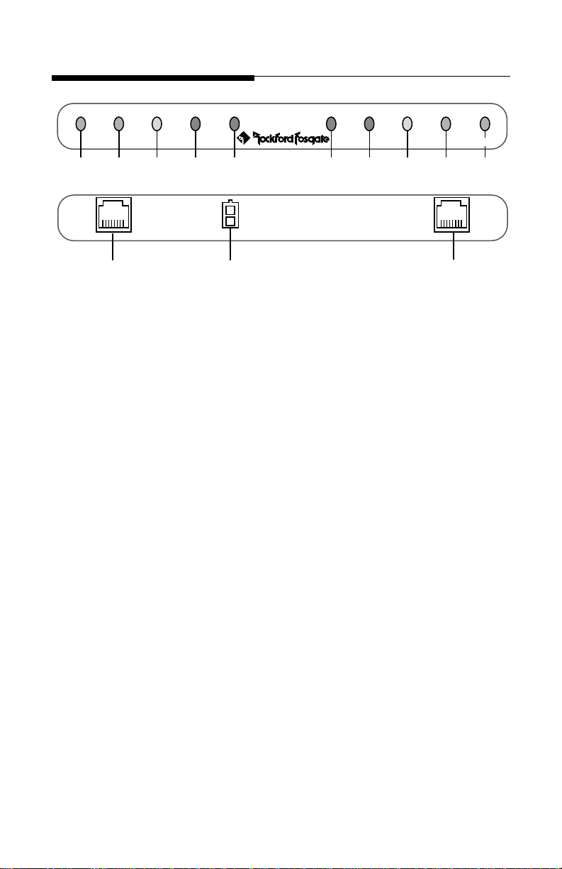
DESIGN FEATURES
POWER SIGNAL MAX CLIP THERMAL THERMAL CLIP MAX SIGNAL POWER
®
1 2 3 4 5 5 4 3 2 1
6
7
®
PSD-1
6
1. POWER Indicator – The POWER LED will illuminate when the
amplifier turns on.
2. SIGNAL Indicator – The SIGNAL LED will illuminate when audio
signal is present at the amplifier.
3. MAX Indicator – The MAX LED will illuminate when the audio signal
has reached its maximum amplified level (approximately –2dB from
clip).
4. CLIP Indicator – The CLIP LED will illuminate when the audio signal
has exceeded (clipped) its maximum amplified level.
5. THERMAL Indicator – The THERMAL LED will illuminate when a
fault is detected by the protection circuitry in the amplifier's power
supply. The power supply protection circuitry monitors overvoltage,
undervoltage and thermal conditions.
6. Data Interface Jacks – The RJ45 interface provides a convenient
connection for the data interface cable.
7. Remote/Dimmer Connector – The mini 2-pin connector provides a
convenient connection for Remote Turn-On and Dimmer input.
– 2 –
Page 7
Stereo/Mono
Left
Remote
Disable
Remote
Enable
8
Remote
Dimmer
9
Mono Right
Stereo Amp
Mono Amp(s)
Stereo Amp
Mono Amp(s)
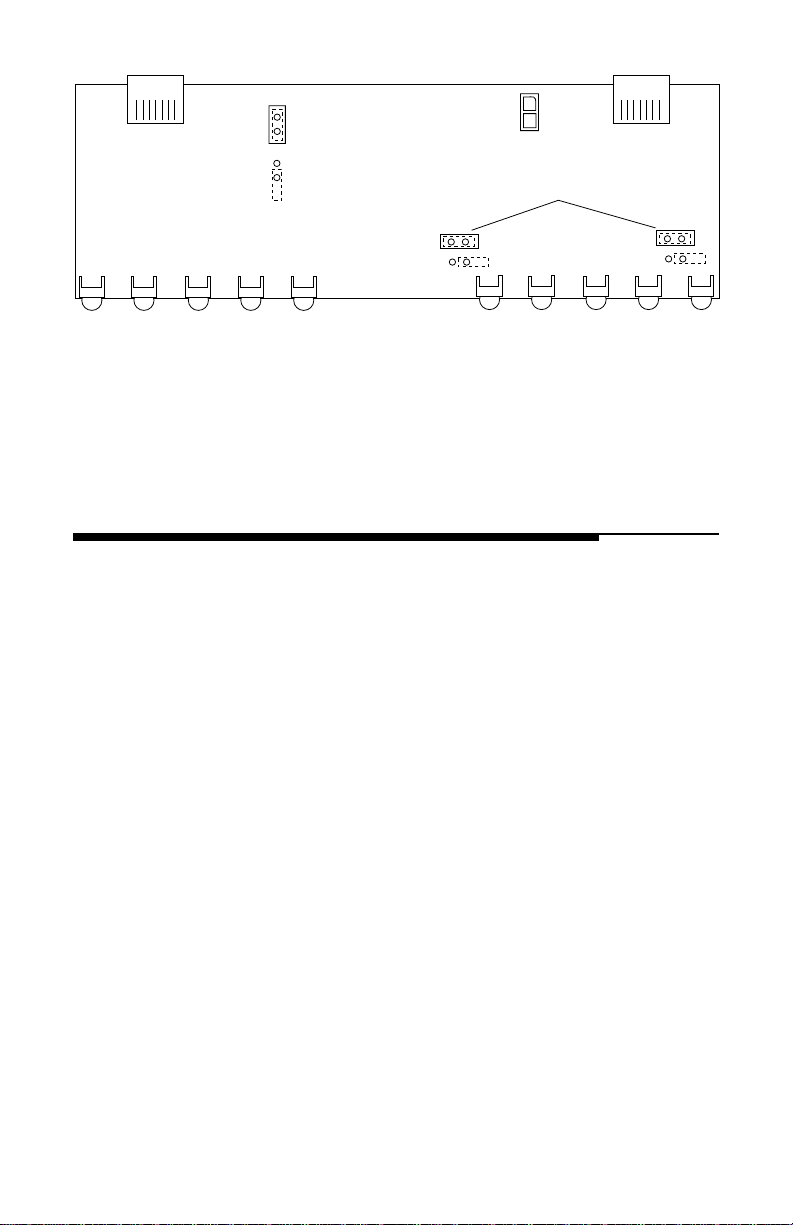
8. Remote Disable/Enable Jumper –The position of this jumper
determines whether the PSD is turned on and off by the amplifier
or with a separate switch.
9. Stereo/Mono Jumpers – These jumpers are used to configure the
PSD for Stereo or Mono amplifier input(s).
INSTALLATION CONSIDERATIONS
The following is a list of tools you will need for installing the PSD:
Battery Post Wrench Soldering Iron (optional)
#1 Phillips Screwdriver Solder (optional)
Wire Strippers (optional) Heat Gun (optional)
1/8" diameter heat shrink tubing (optional)
This section focuses on some of the vehicle considerations for installing
your new PSD. Pre-planning your layout and best wiring routes will save
installation time.
1. For safety, disconnect the negative lead from the battery prior to
beginning the installation.
2. For easier assembly, we suggest you run all wires prior to mounting
your Punch Status Display.
3. Think before you drill! Be careful not to cut or drill into vacuum lines
or electrical wiring when working on any vehicle.
4. Never run wires underneath the vehicle. Running the wires inside the
vehicle provides the best protection.
5. Avoid running wires over or through sharp edges. Use rubber or
plastic grommets to protect any wires routed through metal.
6. ALWAYS protect the battery and electrical system from damage with
proper fusing. Be sure the Remote and Dimmer wires are connected
to an appropriately fused electrical system.
– 3 –
Page 8

MOUNTING LOCATIONS
The Punch Status Display can be installed in a wide range of operating
locations. However, care should be taken to ensure optimum monitoring
without causing distractions under normal driving conditions. Listed
below are the following options for installation.
Engine Compartment
Mounting the Punch Status Display in the engine compartment will void
your warranty. We didn't think you would actually install the PSD in the
engine compartment. We just wanted to make sure you were paying
attention to the installation instructions.
Instrument Panel
Mounting the Punch Status Display in the instrument panel provides
optimum monitoring. The PSD should be securely mounted using the
“Standard Mount” or “ISO Mount” method.
Center Console
Mounting the Punch Status Display in the center console panel provides
optimum monitoring. The PSD should be securely mounted using the
“Standard Mount” or “ISO Mount” method.
Glove Box
Mounting the Punch Status Display in the glove box is adequate, but does
not provide easy monitoring. Glove Box mounting should only be done
if “Instrument Panel” or “Center Console” mounting are not acceptable
(i.e., maintaining integrity of older vehicles with metal dashboards).
Under Dash
Mounting the Punch Status Display under the dash is adequate, but does
not provide easy monitoring. Under dash mounting should only be done
if “Instrument Panel,” “Center Console” or “Glove Box” mounting are not
possible. Mount the PSD to the side of the driver's area to reduce
interference with the parking brake, gear shift or operating pedals.
– 4 –
Page 9

WIRING THE SYSTEM
For safety, disconnect the negative lead from the car battery prior to
beginning the installation.
1. Route the Data Interface Cable inside the vehicle to provide the best
protection. Leave slack at each end of the cable for the connection of
the PSD and amplifier.
2. Configure the Stereo/Mono Jumpers by removing the two Phillips screws
from each side of the PSD that hold the sheet metal top in place. Remove
the sheet metal and locate the Stereo/Mono jumpers on the PC board. To
accept a Stereo amplifier input, both jumpers should be INSTALLED on
the jumper pins. To accept a Mono or pair of Mono amplifier inputs, both
jumpers should be REMOVED from the jumper pins.
3. Configure the Remote Jumper located on the PC board. The position
of this jumper determines whether the PSD is controlled by the
amplifier or separately. When INSTALLED, the Remote Turn-On wire
is disabled and the amplifier will automatically turn on the PSD. When
the jumper is REMOVED, the Remote Turn-On wire is enabled and the
PSD is controlled by an optional switch. Determine which method is
preferable for your particular application. NOTE: The Remote Jumper must
be
enabled
4. When connecting the Remote/Dimmer Harness leads to the electrical
system, solder and heat shrink all connections for a reliable installation. For each connection, cut a 1" piece of heat shrink tubing and slide
over one of the wires. Strip each wire 3/8", then twist together and
solder. Slide the tubing over the connection and shrink the tubing with
a hot air gun until no bare wire is exposed.
when using a Power 250m2, Power 500m or Power 250m.
The Remote Turn-On (Blue) lead should be connected (when Remote
Jumper is enabled) to the remote turn-on or power antenna output
from the source unit. An in-line switch may be used if you would like
to disable the PSD during operation.
The Dimmer (Orange) lead should be connected to the “park light”
or to a switched +12 volt source when the headlights are turned on.
5. Adjust system gains
Although the PSD does monitor the output signal from the amplifier
it is not designed as a replacement for an oscilloscope or other
specialized test equipment.
6. Plug in the Data Interace Cable and Remote/Dimmer Harness into
the rear of the PSD and check for frayed wires or loose connections.
prior
to installing the Punch Status Display
– 5 –
Page 10
INSTALLATION
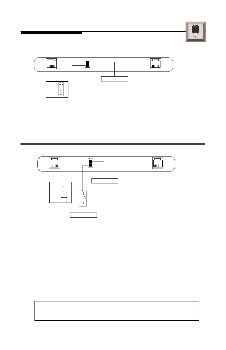
Remote Turn-On/Dimmer Wiring
Do Not
Use
Remote Jumper on
PC Board
Remote
Disable
Orange Wire
Connect to +12V
dimmer or “park
light” lead (optional)
I
® ®
N
S
T
A
L
L
A
T
I
O
N
• Remote Turn-On (Blue Wire)
not used
when Remote Jumper has
been DISABLED (installed)
• Dimmer (Orange Wire) will
dim LEDs
when connected to dimmer
or “park light” lead (+12V when headlights are turned on)
Remote Jumper on
PC Board
Remote
Enable
Blue Wire
Orange Wire
Connect to +12V dimmer or
“park light” lead (optional)
Optional
Switch
Connect to remote turn-on
lead from source unit
• Remove Cover to access Remote Jumper by removing 2 screws on
each side of the PSD
• Remote Turn-On (Blue Wire) connects to source unit's accessory
turn-on lead when Remote Jumper has been ENABLED (removed)
• An Optional Switch can be used to turn off the PSD independently
from the audio system
• Dimmer (Orange Wire) will
dim LEDs
when connected to dimmer
or “park light” lead (+12V when headlights are turned on)
NOTE: The Power 250m2, Power 250m and Power 500m must use
the ENABLED Remote turn-On for proper operation.
– 6 –
Page 11
Stereo/Mono Jumper Configuration (2-Channel Amp)
®®
®®
trans•
ana
I
® ®
N
S
T
A
L
L
A
T
I
O
N
Remote
Disable
Stereo Amp
Remote
Dimmer
Stereo Amp
POWER SIGNAL MAX CLIP THERMAL THERMAL CLIP MAX SIGNAL POWER
®
• Stereo/Mono Jumpers are
installed
• 2-Channel Amp connects to
Stereo/Mono Left
®
on jumper pins
input
PSD-1
– 7 –
Page 12
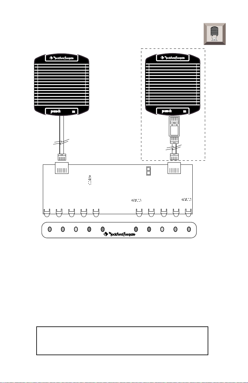
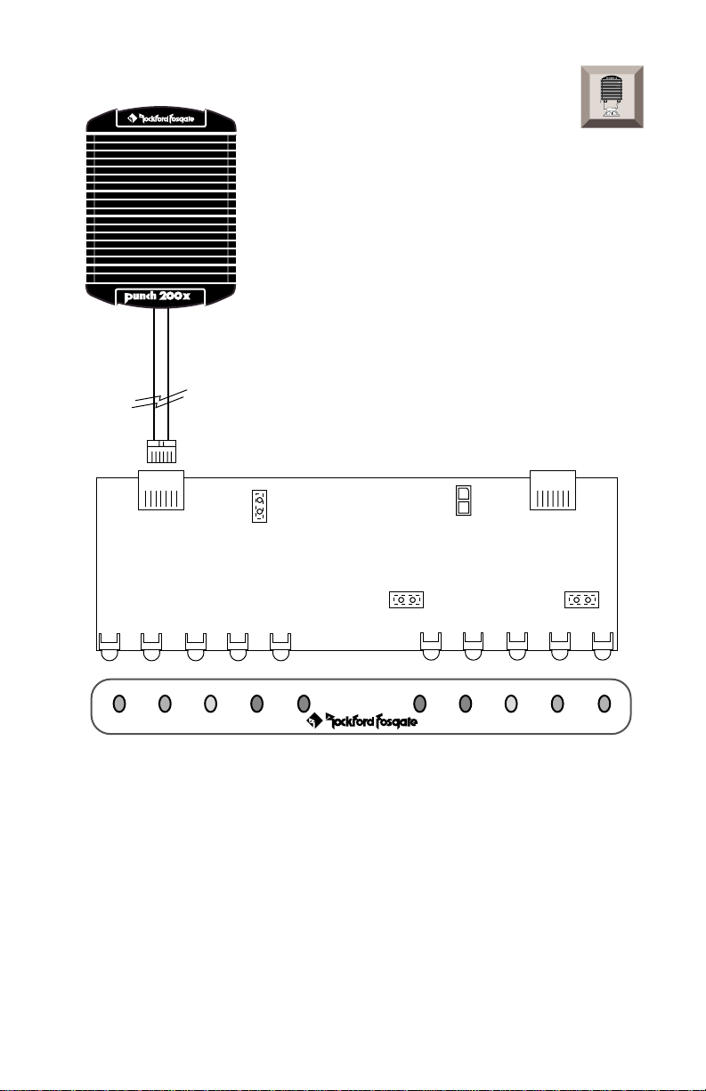
Stereo/Mono Jumper Configuration (Mono Amp/s)
(if using 2 amps)
I
® ®
N
S
T
A
L
L
A
T
I
O
N
®
250
POWER
®®
POWER
®
®®
500
✧
Remote
Remote
Enable
Mono Amp(s)
POWER SIGNAL MAX CLIP THERMAL THERMAL CLIP MAX SIGNAL POWER
®
Dimmer
Mono Amp(s)
®
PSD-1
• Stereo/Mono Jumpers are
• Single Mono Amp connects to
• Left Mono Amp connects to
• Right Mono Amp connects to
removed
from jumper pins
Stereo/Mono Left
Stereo/Mono Left
Mono Right
input
input
input
NOTE: The Power 250m2, Power 250m and Power 500m must
use the ENABLED Remote Turn-On for proper operation.
✧ Adapter used on Power 500m amplifier only
• Power 500 Adapter must connect to the amplifier side of the
Data Interface Cable for proper operation
DO NOT connect Power 500m amplifiers to the PSD
without the appropriate adapter. Please contact Rockford
Customer Service (800-669-9899) for information
– 8 –
Page 13

Standard Mount
Backstrap
I
® ®
N
S
T
A
L
L
A
T
I
O
N
Backstrap Screw
Mounting Bezel
& Washer
(Screw 3/8" Max)
Use rear screw
to secure Bezel
• Install PSD into mounting bezel using the rear screw
• Mount Backstrap securely to the PSD and the instrument panel
• Backstrap Screw should be 3/8" max. (use supplied screw)
ISO Mount
Factory Trim Panel
Screw Factory
Bracket into
Factory Bracket
Adapter
Instrument Panel
1/4" Max
• Install PSD securely into instrument panel with the factory bracket
adapter
• Factory Bracket should align with mounting holes on each side of PSD
• ISO Screws should be 1/4" max. (use existing screws)
– 9 –
Page 14

SYSTEM DIAGRAMS
Single Amp System
Full Range Monitor
POWER SIGNAL MAX CLIP THERMAL THERMAL CLIP MAX SIGNAL POWER
Tweeters
Midrange
®
®®
®®
PSD-1
–
®
Subwoofer
+
– 10 –
Page 15

Bi-Amp System
POWER SIGNAL MAX CLIP THERMAL THERMAL CLIP MAX SIGNAL POWER
POWER SIGNAL MAX CLIP THERMAL THERMAL CLIP MAX SIGNAL POWER
Tweeter/Midrange Monitor
®
®
Subwoofer Monitor
®
®
®®
®®
Subwoofers
PSD-1
PSD-1
– 11 –
®®
®®
Tweeter
Midrange
Tweeter
Midrange
Page 16

Tri-Amp System #1
POWER SIGNAL MAX CLIP THERMAL THERMAL CLIP MAX SIGNAL POWER
POWER SIGNAL MAX CLIP THERMAL THERMAL CLIP MAX SIGNAL POWER
POWER SIGNAL MAX CLIP THERMAL THERMAL CLIP MAX SIGNAL POWER
Tweeter Monitor
®
®
Midrange Monitor
®
®
Subwoofer Monitor
®
®®
®®
®
®®
®®
PSD-1
PSD-1
PSD-1
®®
®®
Subwoofers
®®
®®
– 12 –
Midrange
Tweeters
Page 17

Tri-Amp System #2
POWER SIGNAL MAX CLIP THERMAL THERMAL CLIP MAX SIGNAL POWER
POWER SIGNAL MAX CLIP THERMAL THERMAL CLIP MAX SIGNAL POWER
POWER SIGNAL MAX CLIP THERMAL THERMAL CLIP MAX SIGNAL POWER
Front Stage Monitor
®
®
Rear Stage Monitor
®
®
Subwoofer Monitor
®
®
PSD-1
PSD-1
PSD-1
®®
®®
®®
®®
Subwoofers
®®
®®
Rear Stage
®®
®®
– 13 –
Front Stage
Page 18

ROCKFORD FOSGATE ACCESSORIES
PSD CABLES (CC-1188)
20 foot 8-conductor cables are available separately for the connection
of an additional mono amplifier to Punch Status Display. This will allow
the PSD to accommodate a pair of Mono amplifiers operating individually or a pair of Mono amplifiers bridged.
TROUBLESHOOTING
Symptom Diagnosis Remedy
TROUBLE-
S
H
O
O
T
I
N
G
PSD does not
turn on (Remote
Disabled)
PSD does not
turn on (Remote
Enabled)
Remote Turn-On wire
must be used with a
250m2, 500m or 250m
Data Interface Cable
between amplifier and
PSD is damaged
Amplifier is not working properly
Voltage applied to the
PSD Remote Turn-On
wire is not between 8
and 15.5 or there is no
voltage present
Optional switch (if used)
is damaged or in the
“OFF” position
Data Interface Cable
between amplifier and
PSD is damaged
Enable Remote jumper and
connect Remote Turn-On
(blue wire) to a source of
switched +12V
Check connections, substitute
with known working cable
and repair or replace as necessary
Check connections, substitute
with known working amplifier and repair or replace as
necessary
Check wiring and repair if
necessary. If voltage is above
15.5 volts, have the electrical
system inspected by an authorized car service center
Bypass switch – if PSD turns
on, check connections and
switch position and repair or
replace as necessary
Check connections, substitute
with known working cable and
repair or replace as necessary
Amplifier is not working properly
– 14 –
Check connections, substitute
with known working amplifier and repair or replace as
necessary
Page 19

Symptom Diagnosis Remedy
TROUBLE-
S
H
O
O
T
I
N
G
PSD does not
turn on (Thermal
LED on)
Random LEDs
Illuminate
Both POWER and/or
THERMAL LEDs do
not illuminate
(Stereo Amp Connected)
Both POWER and/
or THERMAL LEDs
illuminate (Mono
Amp Connected)
Amplifier has overheated and activated its
thermal protection
Voltage applied to the
amplifier Remote TurnOn is not between 8 and
15.5 volts
Stereo amplifier is not
connected to proper
input
Single Mono amplifier
is not connected to
proper input
Stereo/Mono jumpers
are removed from
jumper pins
Stereo/Mono jumpers
are installed on jumper
pins
Turn the system off and wait
approximately 15 minutes for
the amplifier to cool down.
Check wiring and repair if
necessary. If voltage is above
15.5 volts, have the electrical
system inspected by an authorized car service center
Connect stereo amplifier to
Stereo/Mono Left input only
Connect single Mono amplifier to Stereo/Mono Left input
only
Check jumper configurations
and repair as necessary
Check jumper configurations
and repair as necessary
LEDs do not dim
(Headlights
turned on)
PSD shuts off when
amp thermals
(Remote Enabled)
Voltage applied to the
Dim (orange) wire is not
between 10.5 and 15.5
volts
Dim (orange) wire is not
connected to a source
that switches to +12
volts when the headlights are turned on
Voltage applied to the
Remote Turn-On (blue)
wire is not between 8
and 15.5 volts or there
is no voltage present
– 15 –
Connect voltmeter to source
of switched +12 volts and
verify voltage. Repair wiring
as necessary or find an alternate +12 volt source
Repair wiring as necessary or
find an alternate +12 volt
switched source
Check wiring and repair if
necessary. If voltage is above
15.5 volts, have the electrical
system inspected by an authorized car service center
Page 20

SPECIFICATIONS
Number of Channels 2
Number of Inputs 2 (Stereo/Mono Left & Mono Right)
Dimmer Level Approximately Half Illumination
Remote Turn-On +8 V to activate
Dimmer +10.5 V to activate
LED Indicator Threshold of Illumination
POWER Amplifier Remote Turn-On
SIGNAL Equivalent to 1 Watt of amplifier power
@ 4 ohms
MAX –2dB from clipping (may vary upon unit)
CLIP Signal Clipping
THERMAL ≥ +90° C (+194° F) amplifier temperature
or protection of power supply due to
under/over voltage
PSD Dimensions:
POWER SIGNAL MAX CLIP THERMAL THERMAL CLIP MAX SIGNAL POWER
®
®
7"
(17.8cm)
Mounting Bezel Dimensions:
2-3/8"
(6cm)
7-1/2"
(19.1cm)
– 16 –
PSD-1
3/4"
(1.9cm)
2-1/4"
(5.7cm)
2-1/16"
(5.2cm)
2-1/4"
(5.7cm)
Page 21

WARRANTY INFORMATION
Rockford Fosgate warrants all electronics to the original consumer/purchaser to be free
from defects in materials or workmanship for a period of three (3) years. We will cover
parts and labor provided the product was purchased from an Authorized Rockford
Fosgate Dealer. This warranty does not apply to any product on which the seals and/
or serial number have been broken, removed, tampered with, defaced or altered in any
manner. This warranty only applies to the original consumer/purchaser and is not
transferable.
Electronics found to be defective during the warranty period will be repaired or
replaced at Rockford Fosgate’s discretion. Repaired or replaced electronics will be
covered by the balance of the original warranty period only. Rockford Fosgate shall
not be responsible for any incidental or consequential damages resulting from a defect
in electronics. Some states do not allow the exclusion or limitation of incidental or
consequential damages, so the previous limitation may not be applicable.
The warranty does not cover any appearance item, any cost or expense related to the
removal or reinstallation of the product, any accessory used in conjunction with the
product, damage to the product resulting from alteration, accident, misuse or abuse,
or improper installation. This warranty does not apply if the parts or labor, which would
otherwise be provided without charge under this warranty, are obtained from any
source other than Rockford Fosgate or an Authorized Rockford Fosgate Service Center.
This warranty is the only express warranty and does not create any implied warranties.
Rockford Fosgate limits its obligations under any implied warranties under state laws
to a period not to exceed the written warranty period. Some states do not allow
limitation on how long an implied warranty lasts, so the above limitation may not
apply. This warranty applies only to products sold in the United States of America or
its possessions. For warranty outside the U.S.A., please contact the nearest Authorized
Rockford Fosgate Dealer. This warranty gives the consumer specific legal rights, and
the consumer may have other rights which vary from state to state.
A defective product must be shipped prepaid to the Authorized Rockford Fosgate
Dealer from which the consumer purchased the product or to the Rockford Fosgate
factory in Tempe, Arizona in the original factory carton or equivalent. Any shipping
loss or damage will be borne by the consumer or the consumer’s shipper. A consumer
returning a product to the factory must call (800) 669-9899 for a Return Authorization
Number. All shipments shall be clearly marked with the Return Authorization Number
on the outside of the shipping carton.
Ship to:
Rockford Corporation
Warranty Repair Department
2055 E. 5th Street
Tempe, AZ 85281 U.S.A.
Return Authorization Number:_________________
– 17 –
Page 22

NTERNATIONAL
I
INFORMATION
– 18 –
Page 23

CONECTANDO EL SISTEMA
Por seguridad, desconecte el borne negativo de la bateria de su coche
antes de comenzar la instalación.
1. Coloque el cable de Interficie de Datos en el interior de su vehiculo
de manera que éste quede protegido. Deje un trozo libre y suelto en
cada extremo del cable para poder conectar el PSD y el Amplificador.
2. Configure el Remote Jumper situado en la placa PC. La posición de
éste jumper determina si el PSD está controlado por el amplificador
o independientemente. Si está colocado, el cable de encendido
remoto es activado y el PSD es controlado por un interruptor
separado. Determine que método prefiere particularmente. NOTA:
El jumper de Remote debe estar colocado cuando use usted un
Power 250m2, un Power 500m o un Power 250m.
3. El cable del encendido remoto (Azul) debe estar conectado (cuando
el jumper de remoto también está conectado) al encendido remoto
o a la salida de alimentación de la antena de su unidad fuente. Debe
utilizar un interruptor en la própia linea o cable si quiere desactivar
el PSD.
4. El cable de Dimmer (Naranja) debe estar conectado a las “luces de
posición” o a una fuente que entregue +12 voltios cuando los faros
sean encendidos.
E
SPAÑOL
5. Ajuste las ganancias del sistema antes de instalar el visualizador del
estado de Punch.
Aunque el PSD permita monitorizar la señal del amplificador, no está
diseñado para recemplazar un osciloscópio u otro aparato de test
especializado.
– 19 –
Page 24

INSTALACIÓN
Conexionado del encendido remoto y del Dimmer
No usar
Jumper de remoto en
la placa de PC
Remote
Disable
Cable Naranja
Conectar a +12V
Dimmer o “Luces de
posición” (opcional)
I
® ®
N
S
T
A
L
L
A
T
I
O
N
• Encendido Remoto (cable Azul)
no usado
cuando el jumper del
remoto ha sido desactivado
• Dimmer (cable Naranja)
oscurecerá los LEDs
cuando sea conectado
al cable de dimmer o de “luces de posición” (+12 V cuando los faros
sean encendidos
Jumper de remoto
en la paca de PC
Remote
Disable
Cable Azul
Cable Naranja
Conectar a +12V. Dimmer o
“Luces de posición”
Interruptor
Opcional
(opcional)
Conectar al cable del
encendido remoto de la
unidad fuente
• Levante la cubierta para acceder al jumper de remoto sacando los
dos tornillos
• Conecte el cable del encendido remoto (Azul) al encendido remoto
si el jumper ha sido activado
• Un interruptor opcional puede ser usado para desconectar el PSD
independientemente del sistema de sonido
• Dimmer (cable Naranja)
oscurecerá los LEDs
cuando sea conectado
al cable de dimmer o de “luces de posición” (+12 V cuando los faros
sean encendidos
NOTA: El Power 250m2, Power 500m y Power 250m deben usar el
encendido remoto en modo activado para un mejor funcionamiento
– 20 –
Page 25

Configuración de los Jumpers (Amplificador de 2 canales)
®®
®®
trans•
ana
I
® ®
N
S
T
A
L
L
A
T
I
O
N
Remote
Disable
Stereo Amp
Remote
Dimmer
Stereo Amp
POWER SIGNAL MAX CLIP THERMAL THERMAL CLIP MAX SIGNAL POWER
®
• Los jumpers Stereo/Mono están
• 2-Channel Amp se conecta a la entrada
®
colocados
en los pines para jumpers
Stereo/Mono Left
PSD-1
– 21 –
Page 26

Configuración de los Jumpers (Amplificador/es Mono)
(if using 2 amps)
I
® ®
N
S
T
A
L
L
A
T
I
O
N
®
250
POWER
®®
POWER
®
500
®®
✧
Remote
Dimmer
Remote
Enable
Mono Amp(s)
POWER SIGNAL MAX CLIP THERMAL THERMAL CLIP MAX SIGNAL POWER
®
®
Mono Amp(s)
PSD-1
• Los Jumpers Stereo/Mono son
• Single Mono Amp se conecta a la entrada
• Mono Amp Left se conecta a la entrada
• Mono Amp Right se conecta a la entrada
sacados
de los pines para jumpers
Stereo/Mono Left
Stereo/Mono Left
Mono Right
NOTA: El Power 250m2, Power 500m y Power 250m deben usar el
encendido remoto en modo activado para un mejor funcionamiento
✧ Adaptador utilizado sólo en los amplificadores Power 500m
• El Adaptador del Power 500m debe conectar la banda del amplificador
del cable de Interficie de Datos para un funcionamiento correcto
No Conecte los amplificadores Power 500m al PSD sin el
adaptador apropiado. Por favor, contacte con el service al
cliente de Rockford para más información (800-669-9899)
– 22 –
Page 27

BRANCHEMENT DU SYSTÈME
Pour votre sécurité, déconnectez la borne négative de la batterie avant
de commencer l'installation.
1. Faire passer le cable d'interface dans le véhicule de manière à le
protéger au maximum. Laisser du mou à chaque extrémité du cable
afin de connecter le PSD et l'amplificateur.
2. Configurer le pontage (Remote Jumper) situé sur le circuit imprimé.
La position de ce jumper détermine si le PSD est contrôlé par
l'amplificateur ou séparément. Lorsque le jumper est installé, le fil
de commande est désactivé et l'amplificateur allume
automatiquement le PSD. Lorsque le jumper est enlevé, le fil de
commande d'allumage est activé et le PSD est contrôlé par un
interrupteur séparé. C'est à vous de déterminer quelle méthode
d'allumage du PSD convient le mieux à votre application. NOTE: Le
jumper d'allumage doit être enlevé lorsque le PSD est raccordé à
un Power 250m2, Power 500m ou Power 250m.
3. Lorsque le jumper de commande est enlevé, le fil (bleu) de commande
d'allumage doit être connecté au fil de commande de l'antenne
électrique de l'autoradio. Il est possible d'installer un interrupteur
sur ce fil si vous désirez éteindre le PSD.
F
RANÇAIS
4. Le fil (orange) du dimmer peut être connecté aux feux de position
ou à un fil fournissant un 12 volts positif lorsque les phares sont
allumés.
5. Ajustez les gains AVANT d'installer le Punch Status Display (PSD).
Bien que le PSD contrôle le signal de sortie de l'amplificateur il n'est
pas conçu pour remplacer un oscilloscope ou tout autre appareil de
test spécialisé.
– 23 –
Page 28

INSTALLATION
Commande d'allumage / Dimmer
ne pas
utiliser
Pontage (“jumper”) Remote sur
le circuit imprimé
Remote
Disable
Connecter à un fil 12 volts variable
(dimmer) ou aux feux de position
fil orange
(facultatif)
I
® ®
N
S
T
A
L
L
A
T
I
O
N
• La commande d'allumage (fil bleu)
n'est pas utilisé
lorsque le jumper
est branché.
• Le dimmer (fil orange) va assombrir les LEDs lorsqu'il est connecté
à un fil variable (dimmer) ou aux feux de position (+12 volts lorsque
les phares sont allumés).
Pontage (“jumper”) Remote
sur le circuit imprimé
Remote
Disable
fil bleu
fil orange
Connecter à un fil 12 volts variable
(dimmer) ou aux feux de position
(facultatif)
Interrupteur
facultatif
connecter au fil de
commande d'antenne de
l'autoradio
• Enlever le couvercle du boîtier pour accéder au jumper de commande
en retirant les deux vis.
• La commande d'allumage (fil bleu) se branche sur la sortie antenne
de l'autoradio lorsque le jumper remote est enlevé.
• Un interrupteur supplémentaire peut être branché indépendamment
du système audio
• Le dimmer (fil orange) va assombrir les LEDs lorsqu'il est connecté
à un fil variable (dimmer) ou aux feux de position (+12 volts lorsque
les phares sont allumés).
NOTE: Il faut activer la fonction “remote” et utiliser le fil bleu pour les
modèles d'amplis suivants:
Power 250m2, Power 500m et Power 250m.
– 24 –
Page 29

Configuration du Pontage Mono/Stéréo (Amplis deux)
®®
®®
trans•
ana
I
® ®
N
S
T
A
L
L
A
T
I
O
N
Remote
Disable
Stereo Amp
Remote
Dimmer
Stereo Amp
POWER SIGNAL MAX CLIP THERMAL THERMAL CLIP MAX SIGNAL POWER
®
• Les pontages Stéréo/Mono sont
• L'ampli stéréo se branche sur l'entrée de gauche
®
placés
(stereo/mono left)
PSD-1
– 25 –
Page 30

Configuration du Pontage Mono/Stéréo (Amplis mono)
(si deux amplis sont utilisés)
I
® ®
N
S
T
A
L
L
A
T
I
O
N
®
250
POWER
®®
POWER
®
500
®®
✧
Remote
Dimmer
Remote
Enable
Mono Amp(s)
POWER SIGNAL MAX CLIP THERMAL THERMAL CLIP MAX SIGNAL POWER
®
®
Mono Amp(s)
PSD-1
• Les pontages Stéréo/Mono sont
• Un seul ampli mono se branch sur l'entrée de gauche
• L'ampli mono de gauche se branche sur l'entrée de gauche
Mono Left
)
• L'ampli mono de droite se branche sur l'entrée de droit
enlevés
(Stereo/Mono Left
(Stereo/
(Mono Right
ATTENTION: Avec les amplis 250m2, Power 250m et Power 500m il faut
activer l'entrée remote du PSD
✧ Adaptateur utilisé pour le Power 500m seulement
• L'adaptateur pour le Power 500 doit être branche sur le câble de
l'interface de données du coté de l'ampli
NE PAS CONNECTER LE POWER 500 SUR LE PSD SANS
L'ADAPTATEUR PRECONISE!
– 26 –
)
)
Page 31

VERKABELUNG DES SYSTEMS
Zu Ihrer eigenen Sicherheit klemmen Sie bitte das Negativ-Kabel an Ihrer
Batterie ab, bevor Sie mit dem Anschlieβen beginnen
1. Ziehen Sie das Daten-Interface Kabel so durch Ihr Fahrzeug, daβ es
den bestmöglichen Schutz hat. Achten Sie darauf das es nicht
beschädigt werden kann. Lassen Sie an beiden Enden genug Kabel
übrig, daβ Sie problemlos Endstufe und Display anschlieβen können.
2. Einstellen der Remote Jumper auf der Platinenoberfläche. Die Posi-
tion der Jumper entscheidet ob das Display über die Endstufen oder
separat geschaltet wird. Mit eingestecktem Jumper ist die Remote
Leitung ohnc Funktion das Display wird mit dem Verstärker geschaltet.
Wird der Jumper herausgenommen, ist das Remote Kabel in Funktion
das PSD wird dann über einen separaten Schalter aktiviert. Verwenden
Sie, die für Sie günstigere Methode.
Achtung: Der Remote Jumper mu
einer Power 250m2, Power 500m oder Power 250m.
3. Das Remote Einschalt-Kabel (blau) muβ angeschlossen werden,
wenn der Jumper herausgenommen wurde. Es wird verbunden mit
der Schaltleitung des Radios “power Antenne” Sie können einen
getrennten Schalter einsetzen um das PSD ein-oder auszuschalten.
ββ
β herausgenommen werden bei
ββ
4. Das Dimmer Kabel (orange) sollte mit der Instrumentenbeleuchtung
Ihres Fahrzeuges geschaltet werden, das gibt Ihnen die Moglichkeit
die LEDs in der Helligkeit zu regulieren. Oder Sie verwenden +12
Volt Kabel des Abblendlichtes.
5. Stellen Sie erst die Gains Ihrer Anlage ein bevor Sie das Status
Display installieren. Das Status Display kann das Ausgangs-Signal
der Endstufe anzeigen, es dient aber nicht als Ersatz für ein Oszilloscope
oder anderes Testequipment.
– 27 –
D
EUTSCH
Page 32

EINBAU
Remote Einschalt-Kabel/Dimmer-Kabel
Nicht
benutzen
Remote Jumper auf
der Platine
Remote
Disable
Orangenes Kabel
mit +12 Volt der
Instrumentenbeleuchtung
verbinden
I
® ®
N
S
T
A
L
L
A
T
I
O
N
• Remote Einschalt Kabel
nicht verwenden
(blaues Kabel) wenn der
Remote Jumper auf Disabled steht
• Dimmer Kabel (Orange) reguliert die LEDs, wenn das Kabel mit der
Instrumentenbeleuchtung Ihres Fahrzeuges verbunden wird (Oder
Sie verwenden +12 Volt Kabel des Abblendlichtes.)
entfernen Sie den Jumper
von der Platine
Remote
Disable
Blaues Kabel
Orangenes Kabel
verbinden Sie dieses mit +12 Volt des
Dimmers der Instrumentenbeleuchtung
zusätzlicher
Schalter
Verbinden Sie dieses mit
dem Remote Kabel Ihres
Radios
• Öffnen Sie den Deckel, um an die Remote Jumper zu gelangen,
durch Lösen der beiden Schrauben auf jeder Seite
• Remote Einschalt-Kabel (blau) zum Anschluβ an das Remote Kabel
Ihres Radios, dabei sollte der Jumper auf Enabled stehen
• Ein zusätzlicher Schalter kann verwendet werden um das PSD
getrennt vom Audio System zu schalten
• Das Dimmer Kabel (Orange) bestimmt die Helligkeit der LEDs, wenn
es mit dem Dimmer oder der Instrumentenbeleuchtung des Fahrzeuges
verbunden wird (oder Sie verwenden +12 Volt Kabel des
Abblendlichtes.).
Achtung: Bei der Power 250m2, Power 250m und Power 500m mu
die Stellung Enabled gewählt werden, um ein einwandfreies
Funktionieren zu gewähren.
– 28 –
β
Page 33

Jumper Einstellungen (bei 2 Kanal Endstufen)
®®
®®
trans•
ana
I
® ®
N
S
T
A
L
L
A
T
I
O
N
Remote
Disable
Stereo Amp
Remote
Dimmer
Stereo Amp
POWER SIGNAL MAX CLIP THERMAL THERMAL CLIP MAX SIGNAL POWER
®
®
PSD-1
• Bei Stereo- oder Mono- Betrieb müssen die Jumper eingesetzt sein
• Bei 2 Kanal Endstufen im Stereo/Mono Betrieb bitte den linken
Eingang verwenden
– 29 –
Page 34

Jumper Einstellung (Betreib von Mono Endstufen)
(if using 2 amps)
I
® ®
N
S
T
A
L
L
A
T
I
O
N
®
250
POWER
®®
POWER
®
500
®®
✧
Remote
Dimmer
Remote
Enable
Mono Amp(s)
POWER SIGNAL MAX CLIP THERMAL THERMAL CLIP MAX SIGNAL POWER
®
®
Mono Amp(s)
PSD-1
• Im Stereo/Mono Betrieb sind die Jumper nicht eingesteckt
• Bei einer Mono-Endstufe im Stereo/Mono Betrieb verwenden Sie den
linken Eingang
• Beim Betrieb Mono Endstufe links, den linken Eingang verwenden
• Beim Betrieb Mono Endstufe rechts, den rechten Eingang verwenden
Achtung: Bei der Power 250m2, Power 250m und Power 500m muβ die
Stellung Enabled gewählt werden, um ein einwandfreies Funktionieren zu
gewähren.
✧ Zum Anschlu
ββ
β der Power 500m benötigen Sie einen Adapter
ββ
• Den Power 500m Adapter müssen Sie verwenden, um einen
einwandfreien Betrieb zu garantieren
Verbinden Sie niemals eine Power 500m and ein PSD ohne
den richtigen Adapter. Für Fragen rufen Sie unseren Service
an: 04207-5046 Germany, 071-424647 Swiss und 0663839121 Austria.
– 30 –
Page 35

CABLARE IL SISTEMA
Per motivi di sicurezza, disconnettere il cavo negativo dalla batteria
prima di iniziare l'installazione.
1. Passare il cavo di interfaccia dati all'interno dell'auto con il percorso
che permette la massima protezione. Lasciare un po’ di cavo in ecesso
ad ogni estremitá del cavo per permettere la connessione
all'amplifciatore e al PSD.
2. Configurare i ponticelli del consenso che sono positionati sul circuito
stampato. La posizione di questi ponticelli determina se il PSD sará
controllato dagli amplificatori o meno. Quando il ponticello é installato,
il cavo di consenso é disabilitato e gli amplificatori accendono
automaticamente il PSD. Quando il ponticello é rimosso, il lcavo di
consenso é abilitato e il PSD é controllato da un interruttore esterno.
Decidete quale configurazione é preferibile per la vostra
configurazione. NOTA: Il ponticello non deve essere installato
quando si impiegano il Power 250m2, il Power 500m ed il Power
250m.
3. Il cavo di consenso dell'accensione (blu) deve essere collegato
(quando il ponticello del consenso é stato rimosso) al cavo id
accensione degli amplificatori o dell'antenna elettrica proveniente
dall'autoradio É possibile inserire un interruttore supplementare per
disabilitare il PSD.
4. Il cavo dell'illuminazione (anarncione) deve essere collegato alle luci
di posizione o ad una alimentazione +12 volt presente con le luci
accese.
5. Regolate i livelli del sistema prima di installare il PSD, che, anche se
monitorizza il segnale di uscita dell'amplificatore, non é stato progettato
per sostituire oscilloscopi o altri strumenti di misura.
– 31 –
ITALIANO
Page 36

INSTALLAZIONE
Cablaggio del consenso ed illuminazione
Non
usare
Ponticello di consenso
sul circuito stampato
Remote
Disable
• Cavo di consenso di accensione (blu) non impiegato quando il
ponticello é inserito
• Il cavo dell'illuminazione (arancione) abbassa la luminositá dei LED
quando le luci dell'auto sono accese
Ponticello di consenso
sul circuito stampato
Remote
Disable
Cavo arancione
Connettere alle luci di
posizione (opzionale)
Cavo arancione
Connettere alle luci di
posizione (opzionale)
Interruttore
opzionale
I
® ®
N
S
T
A
L
L
A
T
I
O
N
Cavo Blu
Collegare al cavo di
consenso dell'accensione
dell'autoradio
• Rimuovere il coperchio del PSD togliendo le due viti per parte per
accedere al ponticello di configurazione del consenso di accensione
• Il cavo di consenso di accensione (blu) deve essere collegato
all'accensione degli amplificatori quando il ponticello é disinserito
• Un interruttore opzionale puó essere impiegato per spegnere il PSD
in modo indipendente dal sistema audio
• Il cavo dell'illuminazione (arancione) abbassa la luminositá dei LED
quando le luci dell'auto sono accese
NOTA: Il ponticello non deve essere installato quando si impiegano il
Power 250m2, Power 250m and Power.
– 32 –
Page 37

Configurazione dei ponticelli (amplificatori 2 canali)
®®
®®
trans•
ana
I
® ®
N
S
T
A
L
L
A
T
I
O
N
Remote
Disable
Stereo Amp
Remote
Dimmer
Stereo Amp
POWER SIGNAL MAX CLIP THERMAL THERMAL CLIP MAX SIGNAL POWER
®
• I ponticelli Stereo/Mono sono
installati
®
sui pin
PSD-1
• L'amplificatori 2 canali é connesso all'ingresso sinistro stereo/mono
– 33 –
Page 38

Configurazione dei ponticelli (amplificatori mono)
(if using 2 amps)
I
® ®
N
S
T
A
L
L
A
T
I
O
N
®
250
POWER
®®
POWER
®
500
®®
✧
Remote
Dimmer
Remote
Enable
Mono Amp(s)
POWER SIGNAL MAX CLIP THERMAL THERMAL CLIP MAX SIGNAL POWER
®
®
Mono Amp(s)
PSD-1
• I ponticelli Stereo/Mono sono
rimossi
dai pin
• L'amplificatore mono singolo é collegato all'ingresso sinistro
stereo/mono
• L'amplificatore mono sinistro é collegato all'ingresso stereo/
mono sisistro
• L'amplificatore mono destro é collegato all'ingresso destro mono
NOTA: Il ponticello non deve essere installato quando si
impiegano il Power 250m2, Power 250m and Power.
✧ L'adattatore é impiegato solo con il Power 500m
• L'adattatore per il Power 500m deve essere collegato vicino
all'amplificatore per il corretto funzionamento
Non collegate l'amplificatore Power 500m al PSD senza
l'apposito adattatore. Contattate il distributore Rockford
Fosgate per ulteriori informazioni.
– 34 –
Page 39

3/96
MAN-1208-A
Rockford Fosgate
Rockford Corporation
546 South Rockford Drive
Tempe, Arizona 85281 U.S.A.
In U.S.A., (602) 967-3565
In Europe, Fax (49) 4207-801250
In Japan, Fax (81) 559-79-1265
 Loading...