

Page 1
4CH AMPLIFIERS
R250-4
Total
RMS Power
Birth Date:
Serial Number:
Date of Purchase:
Installation & Operation
Page 2
0U[YVK\J[PVU
Dear Customer,
Congratulations on your purchase of the world’s finest brand of car audio
amplifiers. At Rockford Fosgate we are fanatics about musical reproduction at its best, and we are pleased you chose our product. Through
years of engineering expertise, hand craftsmanship and critical testing
procedures, we have created a wide range of products that reproduce
music with all the clarity and richness you deserve.
For maximum performance we recommend you have your new Rockford
Fosgate product installed by an Authorized Rockford Fosgate Dealer,
as we provide specialized training through Rockford Technical Training
Institute (RTTI). Please read your warranty and retain your receipt and
original carton for possible future use.
Great product and competent installations are only a piece of the puzzle
when it comes to your system. Make sure that your installer is using
100% authentic installation accessories from Rockford Fosgate in your
installation. Rockford Fosgate has everything from RCA cables and
speaker wire to power wire and battery connectors. Insist on it! After all,
your new system deserves nothing but the best.
To add the finishing touch to your new Rockford Fosgate image order
your Rockford accessories, which include everything from T-shirts to
jackets.
Visit our web site for the latest information on all Rockford products
;
www.rockfordfosgate.com
or, in the U.S. call 1-800-669-9899 or FAX 1-800-398-3985. For all other
countries, call +001-480-967-3565 or FAX +001-480-966-3983.
If, after reading your manual, you still have questions regarding this product, we recommend that you see your Rockford Fosgate dealer. If you need
further assistance, you can call us direct at 1-800-669-9899. Be sure to
have your serial number, model number and date of purchase available
when you call.
79(*;0*,:(-,:6<5+
Continuous exposure to sound pressure levels over 100dB may cause
permanent hearing loss. High powered auto sound systems may
produce sound pressure levels well over 130dB. Use common sense
and practice safe sound.
79(;08<,A<5,i*6<;,:(5:90:8<,:
Une exposition continue à des niveaux de pression acoustique upérieurs à
100 dB peut causer une perte d’acuité auditive permanente. Les systèmes
audio de forte puissance pour auto peuvent produire des niveaux de
pression acoustique bien au-delà de 130 dB. Faites preuve de bon sens et
pratiquez une écoute sans risques
79(*;08<,,3:650+6:,.<96
El contacto continuo con niveles de presión de sonido superiores a 100
dB puede causar la pérdida permanente de la audición. Los sistemas de
sonido de alta potencia para automóviles pueden producir niveles de
presión de sonido superiores a los 130 dB. Aplique el sentido común y
practique el sonido seguro.
79(2;0A0,9,5:0,:0*/,9,5:6<5+
Fortgesetzte Geräuschdruckpegel von über 100 dB können beim
Menschen zu permanentem Hörverlust führen. Leistungsstarke
Autosoundsysteme können Geräuschdruckpegel erzeugen, die weit über
130 dB liegen. Bitte wenden Sie gesunden Menschenverstand an und
praktizieren Sie sicheren Sound.
Table of Content
2 Introduction
3 Specifications
4-5 Design Features
6-9 Installation
10 Operation
11 Troubleshooting
12-16 Additional Languages
20 Limited Warranty Information
Installation Considerations
Mounting Locations
Battery and Charging
Wiring the System
Adjusting Gain / Crossover
Punch Bass / Remote Punch Level Control
French
Spanish
German
Italian
6::,9=(;,3,9,.63,+,3:<656:,5A(7,90*630
La costante esposizione a livelli di pressione acustica al di sopra dei
100dB possono causare la perdita permanente dell’udito. I sistemi
audio ad alta potenza possono produrre livelli di pressione acustica ben
superiori ai 130dB. Si consiglia il buon senso e l’osservanza delle regole
del suono senza pericoli
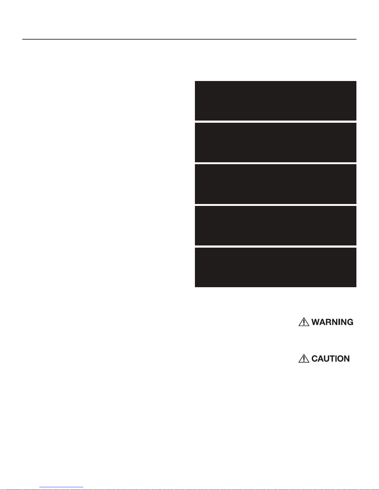
Safety
This symbol with “WARNING” is intended
to alert the user to the presence of important
instructions. Failure to heed the instructions
will result in severe injury or death.
This symbol with “CAUTION” is intended to
alert the user to the presence of important
instructions. Failure to heed the instructions
can result in injury or unit damage.
sTo prevent injury and damage to the unit, please read and follow the
instructions in this manual. We want you to enjoy this system, not get
a headache.
sIf you feel unsure about installing this system yourself, have it installed
by a qualified Rockford Fosgate technician.
sBefore installation, disconnect the battery negative (-) terminal to
prevent damage to the unit, fire and/or possible injury.
©2011 Rockford Corporation. All Rights Reversed. ROCKFORD FOSGATE associated logos where applicable are registered trademarks of Rockford
Corporation in the United States and/or other countries. All other trademarks are the property of their respective owners. Specifications subject to change without notice.
2
Page 3

:WLJPÄJH[PVUZ
Model
Rated Power
*Continuous Power Rating (RMS)
Measured @ 14.4V
Crossover Slope 12dB/Oct
Crossover Frequency HP Fixed 80Hz
Punch Bass 0/6/12dB @ 45Hz
Operating Voltage 9 - 16V DC
Frequency Response 20Hz - 20kHz ± 1dB
Battery Fuse Rating
(not supplied) 40A
THD+N @ Rated Power <1.0 @ 4 ohms
Input Sensitivity 150mV - 8V
Input Impedance 20k
S/N Ratio CEA 2006 >70
S/N Ratio @ Rated Power >90
R250-4
40x4 @ 4 ohms
65x4 @ 2 ohms
125x2 @ 4ohms(bridged)
LP Variable 50Hz - 250Hz
Channel Separation >50
Common Mode Rejection Ratio >55
Damping Factor >200
Dimensions (LxWxH) 11.6” x 7.7” x 2.4”
(29.4cm x 19.6cm x 6.1cm)
CEA 2006
Power ratings on Rockford Fosgate amplifiers conform to CEA-2006 industry standards. These guidelines
mean your amplifier’s output power ratings are REAL POWER numbers, not inflated marketing ratings.
3
Page 4
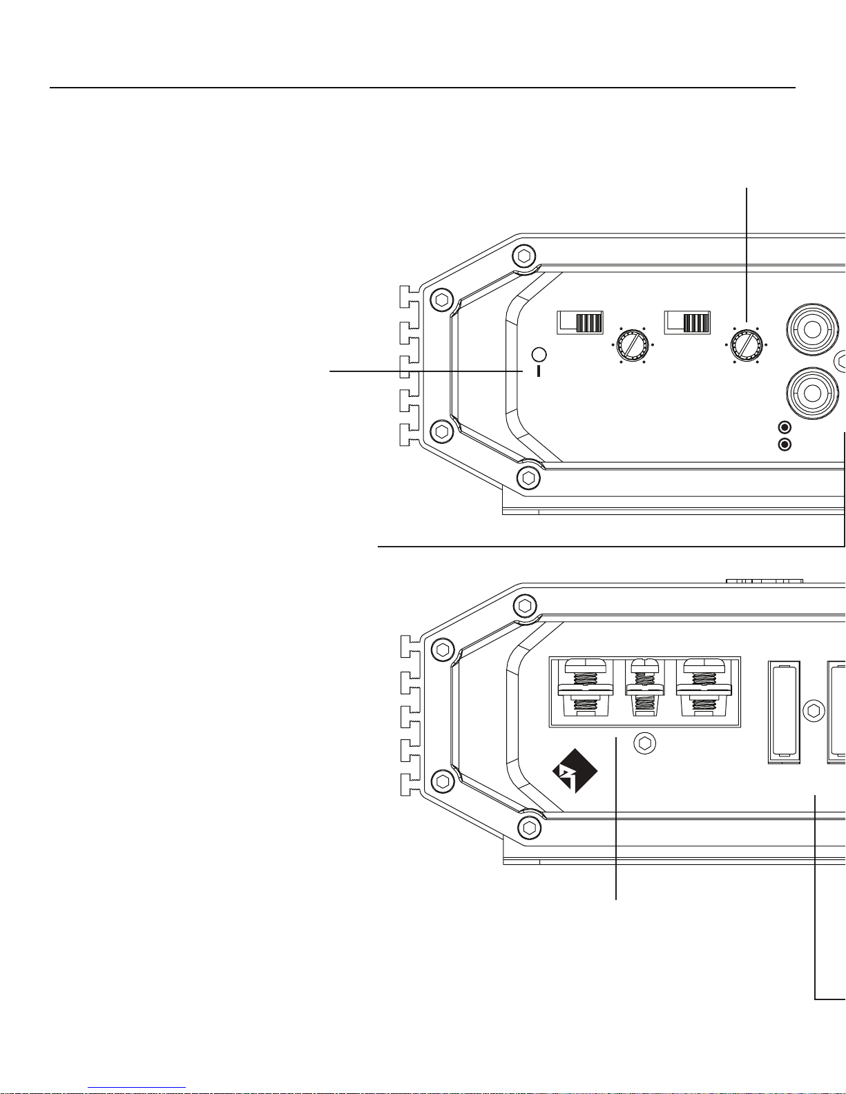
+LZPNU-LH[\YLZ
P
Gain Control
The input gain control is preset to match the output
of most source units.
Power LED
Power LED illuminates blue when
the unit is turned on.
RCA Input Jacks
The industry standard RCA jacks provide an easy connection
for signal level input. They are nickel-plated to resist the signal
degradation caused by corrosion. The Pass-Thru provides a convenient source for daisy-chaining an additional amplifier without
running an extra set of RCA cables from the front of the vehicle to
the rear amplifier location.
381&+%$66
G%G%G%
POWER
/3²$3²+3+]
100 175
75 225
50
250
)5217)5(4
Hz
/3/RZ3DVV2QO\
57
39
1
11
FRONT
GAIN
LEFT
RIGHT
IN
FRONT
B+REMGND
FUSE
4
20A 20
Power/REM Terminals
The power and ground are nickel-plated clamp wire connectors and will
accommodate 4 AWG #8 (up to 1/2”) spade or ring style connectors.
The nickel-plated clamp wire connector and will accommodate 8 AWG
#8 (up to 3/8”) spade or ring style connectors.(This terminal is used to
remotely turn-on and turn-off the amplifier when +12V DC is applied.)
Page 5

Crossover Switch
Selectable switch for 80Hz High-Pass (HP),All Pass (AP), or Low-Pass (LP) operation.
Variable Crossover
Is a built-in 12dB/octave Butterworth filter with a crossover
point variable from 50Hz to 250Hz.
+LZPNU-LH[\YLZ
UT
REAR
FRONT
57
39
1
11
REAR
GAIN
LEFT
RIGHT
+
–
381&+%$66
G%G%G%+3+]²$3²/3
100 175
75 225
50
250
5($5)5(4
Hz
/3/RZ3DVV2QO\
RIGHTLEFT
+
–
PROTECT
Protect LED
Protect LED illuminates red if a short circuit or to low of
an impedance is detected at the speaker connections. The
amplifier will automatically shut down if this occurs.
Punch Bass
This is an adjustable Bass level control centered at
45Hz @ 12dB/octave.
REAR
A
BRIDGED
0LQLPXP
SPEAKERS
Speaker Terminals
The heavy duty, nickel-plated clamp wire connectors (+ and -) will
accommodate 8 AWG #8 (up to 3/8”) spade or ring style connectors.
Fuses
These ATC fuses are easily accessible in case of failure.Always replace fuses with same
type and rating. See Specifications for fuse ratings.
illus.-1.1
5
Page 6

0UZ[HSSH[PVU
Contents
sR250-4 - Prime 4 Channel Amplifier
sMounting Hardware
sInstallation & Operation Manual
Installation Considerations
The following is a list of tools needed for installation:
sFuse-holder and fuse. (See
specifications for fuse rating)
sVolt/Ohm Meter
sWire strippers
sWire crimpers
sWire cutters
s#2 Phillips screwdriver
sBattery post wrench
This section focuses on some of the vehicle considerations for installing your new amplifier. Pre-planning your system layout and best wiring
routes will save installation time. When deciding on the layout of your new
system, be sure that each component will be easily accessible for making
adjustments.
If you feel unsure about installing this system yourself, have it installed by a qualified
technician.
Before installation, disconnect the battery negative (-) terminal to prevent damage to the unit,
fire and/or possible injury.
Before beginning any installation, follow these simple rules:
sHand held drill w/assorted bits
sAssorted connectors
sAdequate Length—Red
PowerWire
sAdequate Length—Remote
Turn-onWire
sAdequate Length—Black
GroundingWire
working on any vehicle.
7. Never run wires underneath the vehicle. Running the wires inside the
vehicle provides the best protection.
8. Avoid running wires over or through sharp edges. Use rubber or
plastic grommets to protect any wires routed through metal, especially
the firewall.
9. ALWAYS protect the battery and electrical system from damage with
proper fusing. Install the appropriate fuse holder and fuse on the +12V
power wire within 18” (45.7 cm) of the battery terminal.
10. When grounding to the chassis of the vehicle, scrape all paint from
the metal to ensure a good, clean ground connection. Grounding
connections should be as short as possible and always be connected
to metal that is welded to the main body, or chassis, of the vehicle.
Seatbelt bolts should never be used for connecting to ground.
Mounting Locations
Engine Compartment
Never mount this unit in the engine compartment. Mounting the unit in the
engine compartment will void your warranty.
Trunk Mounting
Mounting the amplifier vertically or inverted will provide adequate cooling of the amplifier. Mounting the amplifier on the floor of the trunk will
provide the best cooling of the amplifier.
Passenger Compartment Mounting
Mounting the amplifier in the passenger compartment will work as long as
you provide a sufficient amount of air for the amplifier to cool itself. If you
are going to mount the amplifier under the seat of the vehicle, you must
have at least 1” (2.54cm) of air gap around the amplifier’s heatsink.
Mounting the amplifier with less than 1” (2.54cm) of air gap around the
amplifier’s heatsink in the passenger compartment will not provide proper
cooling and will severely affect the performance of the amplifier and is
strongly not recommended.
1. Be sure to carefully read and understand the instructions before
attempting to install the unit.
2. For safety, disconnect the negative lead from the battery prior to
beginning the installation.
3. For easier assembly, we suggest you run all wires prior to mounting
your unit in place.
4. Route all of the RCA cables close together and away from any high
current wires.
5. Use high quality connectors for a reliable installation and to minimize
signal or power loss.
6. Think before you drill! Be careful not to cut or drill into gas tanks, fuel
lines, brake or hydraulic lines, vacuum lines or electrical wiring when
6
Battery and Charging
Amplifiers will put an increased load on the vehicle’s battery and charging
system. We recommend checking your alternator and battery condition
to ensure that the electrical system has enough capacity to handle the
increased load of your stereo system. Stock electrical systems which are
in good condition should be able to handle the extra load of any Prime
Series amplifier without problems, although battery and alternator life can
be reduced slightly. To maximize the performance of your amplifier, we
suggest the use of a heavy duty battery and an energy storage capacitor.
Wiring the System
If you do not feel comfortable with wiring your
new unit, please see your local Authorized
Rockford Fosgate Dealer for installation.
Page 7

0UZ[HSSH[PVU
Before installation, disconnect the battery negative (-) terminal to prevent damage to the unit,
fire and/or possible injury.
Avoid running power wires near the low level
input cables, antenna, power leads, sensitive
equipment or harnesses. The power wires carry substantial current and could induce noise
into the audio system.
1. Plan the wire routing. Keep RCA cables close together but isolated
from the amplifier’s power cables and any high power auto accessories,
especially electric motors. This is done to prevent coupling the noise
from radiated electrical fields into the audio signal. When feeding
the wires through the firewall or any metal barrier, protect them with
plastic or rubber grommets to prevent short circuits. Leave the wires
long at this point to adjust for a precise fit at a later time.
2. Prepare the RED wire (power cable) for attachment to the amplifier by
stripping 3/8” of insulation from the end of the wire. Crimp the bared
wire into a fork or ring style connector and attach to the B+ terminal.
Tighten the screw to secure the cable in place.
NOTE: The B+ cable MUST be fused 18” or less from the vehicle’s battery.
Install the fuseholder under the hood and ensure connections are water
tight.
3. Trim the RED wire (power cable) within 18” of the battery and splice in
a inline fuse holder (not supplied). See Specifications for the rating of
the fuse to be used. DO NOT install the fuse at this time.
7. Securely mount the amplifier to the vehicle or amp rack. Be careful not
to mount the amplifier on cardboard or plastic panels. Doing so may
enable the screws to pull out from the panel due to road vibration or
sudden vehicle stops.
8. Connect from source signal by plugging the RCA cables into the input
jacks at the amplifier.
Always ensure power is off or disconnected at
the amplifier before connecting RCA cables.
Failure to do so may cause damage to the amplifier and/or connected components.
9. Connect the speakers. Strip the speaker wires 3/8”, crimp the bared
wire into a fork or ring style connectors and attach to the speaker
terminals.Tighten the screw to secure into place. Be sure to maintain
proper speaker polarity. DO NOT chassis ground any of the speaker
leads as unstable operation may result.
10. Perform a final check of the completed system wiring to ensure that all
connections are accurate. Check all power and ground connections
for frayed wires and loose connections which could cause problems.
Install inline fuse near battery connection.
NOTE: Follow the diagrams for proper signal polarity.
This amplifier is not recommended for impedance loads below 2-Ohms stereo and 4-Ohms
bridged.
4. Strip 1/2” from the battery end of the power cable and crimp an
appropriate size ring terminal to the cable. Use the ring terminal to
connect to the battery positive terminal.
5. Prepare the BLACK wire (Ground cable) for attachment to the
amplifier by stripping 3/8” of insulation from the end of the wire.
Crimp the bared wire into a fork or ring style connector and attach to
the GROUND terminal.Tighten the screw to secure the cable in place.
Prepare the chassis ground by scraping any paint from the metal
surface and thoroughly clean the area of all dirt and grease. Strip the
other end of the wire and attach a ring connector. Fasten the cable to
the chassis using a non-anodized screw and a star washer.
NOTE: Keep the length of the BLACK wire (Ground) as short as possible.
Always less than 30”.
6. Prepare the Remote turn-on wire for attachment to the amplifier by
stripping 3/8” of insulation from the end of the wire. Crimp the bared
wire into a fork or ring style connector and attach to the REMOTE
terminal.Tighten the screw to secure the wire in place. Connect the
other end of the Remote wire to a switched 12 volt positive source.
The switched voltage is usually taken from the source unit’s remote
amp on lead. If the source unit does not have this output available, the
recommended solution is to wire a mechanical switch in line with a
12 volt source to activate the amplifier.
7
Page 8

0UZ[HSSH[PVU
4-Channel Stereo
illus.-2.1
8
Page 9

3-Channel (2ch Stereo & 1ch Mono *bridged)
0UZ[HSSH[PVU
illus.-2.2
9
Page 10

6WLYH[PVU
Adjusting Gain
1. Turn amplifier gains to minimum (counter-clockwise).
2. Turn the source unit volume up to 7/8 maximum (or when distortion
is just inaudible).
3. Slowly increase amplifier gain control until adequate volume is
achieved.
NOTE: Best signal to noise and dynamic range are realized with gain set to
minimum. For a more in depth setting procedure, contact Rockford Technical Support.
Avoid setting amplifier gain high as noise and
distortion will greatly increase.
Adjusting Crossover Frequency
Placing the crossover switch in the HP position sets
the amplifier to the 80hz High Pass mode, enabling
frequencies above the cut-off point to pass.
Placing the crossover switch in the AP position sets
the amplifier to the All Pass mode, preventing any
crossover adjustment, allowing all frequencies to
pass.
Placing the crossover switch in the LP position sets
the amplifier to the Low Pass mode, enabling frequencies below the cut-off point to pass, adjustable
between 50-250Hz.Turn the crossover adjustment
knob all the way down.With the system playing, turn
the crossover adjustment knob up slowly until the
desired crossover point is achieved. A good place
to start is at about 80Hz.
illus.-3.1
illus.-3.2
Punch Bass
This works along with the crossover switch on the amplifier. When set to
Low-Pass (LP) operation, this is a variable Bass Boost. Set this to your
personal preference while listening to the system.
dB
illus.-5.1
Over excursion and subsequent damage may
occur at high levels of boost.
Remote Punch Level Control
When connected, the “Gain Control” is linked and allows you to remotely
control the output level of the amplifier from the dash or center console.
10
Page 11

;YV\ISLZOVV[PUN
Troubleshooting
NOTE: If you are having problems after installation follow the Troubleshooting procedures below.
Step 1. Check Amplifier for proper connections. Verify that POWER light
is on. If POWER light is on skip to Step 3, if not continue.
1. Check in-line fuse on battery positive cable. Replace if necessary.
2. Check fuse(s) on amplifier. Replace if necessary.
3. Verify that Ground connection is connected to clean metal on the
vehicle’s chassis. Repair/replace if necessary.
4. Verify there is 9 to 14.4 Volts present at the positive battery and
remote turn-on cable. Verify quality connections for both cables at
amplifier, stereo, and battery/fuseholder. Repair/replace if necessary.
Step 2. Protect light is on.
1. If the Protect light is on, this is a sign of a possible short in the
speaker connections. Check for proper speaker connections and use
a volt/ohm meter to check for possible shorts in the speaker wiring.
Too low of a speaker impedance may also cause Protect to light.
Step 3. Check Amplifier for audio output.
Step 5. Check Amplifier if you experience excess Engine Noise.
1. Route all signal carrying wires (RCA, Speaker cables) away from
power and ground wires.
OR
1. Bypass any and all electrical components between the stereo and the
amplifier(s). Connect stereo directly to input of amplifier. If noise goes
away the unit being bypassed is the cause of the noise.
OR
1. Remove existing ground wires for all electrical components. Reground
wires to different locations. Verify that grounding location is clean,
shiny metal free of paint, rust etc.
OR
1. Add secondary ground cable from negative battery terminal to the
chassis metal or engine block of vehicle.
OR
1. Have alternator and battery load tested by your mechanic. Verify good
working order of vehicle electrical system including distributor, spark
plugs, spark plug wires, voltage regulator etc.
1. Verify good RCA input connections at stereo and amplifier. Check
entire length of cables for kinks, splices, etc. Test RCA inputs for AC
volts with stereo on. Repair/replace if necessary.
2. Disconnect RCA input from amplifier. Connect RCA input from test
stereo directly to amplifier input.
Step 4. Check Amplifier if you experience Turn-on Pop.
1. Disconnect input signal to amplifier and turn amplifier on and off.
2. If the noise is eliminated, connect the REMOTE lead of amplifier to
source unit with a delay turn-on module.
OR
1. Use a different 12 Volt source for REMOTE lead of amplifier.
11
Page 12

>HYYHU[`
Rockford Corporation offers a limited warranty on Rockford Fosgate products on the following terms:
Length of Warranty
Speakers, Signal Processors, PRIME and PUNCH Amplifiers – 1 Year
POWER Amplifiers – 2 Years
Any Factory Refurbished Product – 90 days (receipt required)
What is Covered
This warranty applies only to Rockford Fosgate products sold to consumers by Authorized Rockford Fosgate Dealers in the United States of America or its
possessions. Product purchased by consumers from an Authorized Rockford Fosgate Dealer in another country are covered only by that country’s Distributor and not by Rockford Corporation.
Who is Covered
This warranty covers only the original purchaser of Rockford product purchased from an Authorized Rockford Fosgate Dealer in the United States. In order
to receive service, the purchaser must provide Rockford with a copy of the receipt stating the customer name, dealer name, product purchased and date of
purchase.
Products found to be defective during the warranty period will be repaired or replaced (with a product deemed to be equivalent) at Rockford’s discretion.
What is Not Covered
1. Damage caused by accident, abuse, improper operations,water, theft, shipping.
2. Any cost or expense related to the removal or reinstallation of product.
3. Service performed by anyone other than Rockford or an Authorized Rockford Fosgate Service Center.
4. Any product which has had the serial number defaced, altered, or removed.
5. Subsequent damage to other components.
6. Any product purchased outside the U.S.
7. Any product not purchased from an Authorized Rockford Fosgate Dealer.
Limit on Implied Warranties
Any implied warranties including warranties of fitness for use and merchantability are limited in duration to the period of the express warranty set forth
above. Some states do not allow limitations on the length of an implied warranty, so this limitation may not apply. No person is authorized to assume for
Rockford Fosgate any other liability in connection with the sale of the product.
How to Obtain Service
Contact the Authorized Rockford Fosgate Dealer you purchased this product from. If you need further assistance, call 1-800-669-9899 for Rockford Customer Service. You must obtain an RA# (Return Authorization number) to return any product to Rockford Fosgate. You are responsible for shipment of
product to Rockford.
EU Warranty
This product meets the current EU warranty requirements, see your Authorized dealer for details.
20
Page 13

Installation assistance availible at:
www.rockfordfosgate.com/rftech
112111BCF 1230-57383-02
3OUTH2OCKFORD$RIVEs4EMPE!RIZONA5NITED3TATES
ROCKFORDFOSGATE.COM
$IRECTs4OLL&REE
 Loading...