

Page 1
I
E:
TM
Full
Range
Speakers
Serial
Number:
------
5.25"
6.5"
6"x
Installation
Installation
Instalaci6n
Einbau
Installazione
Date
of
9"
et
y
und
Betrieb
Purchase:
-
R1
-
R1653
-R1693
&
Operation
fonctionnement
funcionamiento
e
funzionamento
------
52
Page 2
SAFETY
Before installatipn,
negative (-) terminaltoprevent
to
the
unit, fire
CARTON CONTENTS
(I)
Set Prime Series
(I)
Set of decorative trim rings
Mounting Hardware
Before beginning
I.
Be
suretocarefully read and understand
install these speakers.
2.
For safety, disconnect the negative lead from
installation.
any
Full
Range Speakers
INSTALLATION CONSIDERATIONS
installation, follow these simple rules:
disconnect
and/or
the
possible injury.
instructions before attempting
the
battery priortobeginning
the
battery
damage
to
the
<Q1"
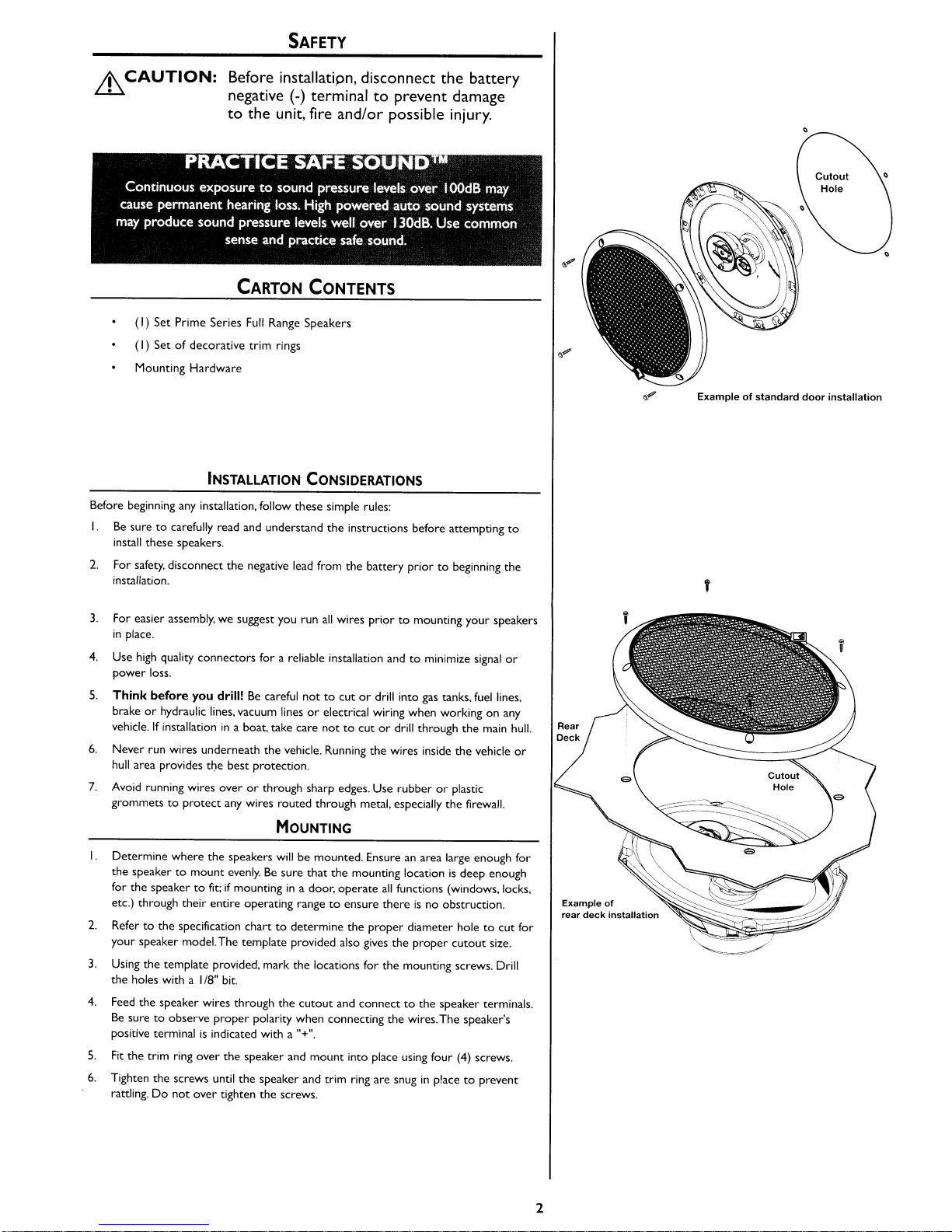
Exampleofstandard
,
door
installation
3.
For easier assembly, we suggest you run
in
place.
4.
Use
high
quality connectors for a reliable installation andtominimize
power loss.
5.
Think
before
you
drill!Becareful
brake
or
hydraulic lines, vacuum linesorelectrical wiring when workingonany
vehicle.
If
installationina boat, take care
6.
Never run wires underneath
hull
area provides tt)e
7.
Avoid running wires
grommets
to
best
protection.
overorthrough sharp edges. Use rubberorplastic
protect
any wires routed through metal, especially
the
all
wires priortomounting your speakers
nottocutordrill into gas tanks,
nottocutordrill
vehicle. Running
the
through
wires inside
the
the
MOUNTING
I.
Determine where
the
speakertomount
for
the
speakertofit:ifmountingina door,
etc.) through their entire operating range
2.
Refertothe specification
your speaker model. The template provided also gives the
3.
Using
the
the
holes with a
4.
Feed the speaker wires through the
Be
suretoobserve
positive terminal
5.
Fit
the trim ring over
6.
Tighten the screws until the speaker and trim ring are snuginplacetoprevent
rattling.
Do
the
speakers
evenly.Besure
template provided, mark the locations for the mounting screws. Drill
1/8"
bit.
proper
is
indicated with a "+".
the
not
over tighten the screws.
willbemounted. Ensureanarea large enough for
that
the
mounting locationisdeep enough
operate
all
functions (windows. locks,
to
ensure thereisno obstruction.
charttodetermine
cutout
polarity when connecting the wires.The speaker's
speaker and
the
proper
diameter holetocut
proper
cutout
and connecttothe speaker terminals.
mount
into place using four (4) screws.
signal
fuel
the
main
vehicle
firewall.
lines,
size.
or
hull.
or
for
Rear
Deck
Example
rear
deck
of
installation
2
Page 3
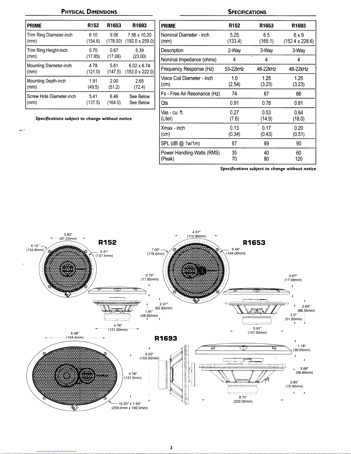
PHYSICAL
DIMENSIONS
SPECIFICATIONS
PRIME
Trim
Ring
(mm)
Trim
Ring
(mm)
Mounting
(mm)
Mounting
(mm)
Screw
Hole
(mm)
Specifications
Diameter-inch
Height-inch
Diameter-inch
Depth-inch
Diameter-inch
subject
R152
6.10
(154.6)
(17.85) (17.08)
(121.0)
(49.5) (51.2)
(137.5) (164.0)
to
change
(178.00)
0.70
4.78
1.91
5.41
without
Rl653
9.06
0.67
5.61
(147.5)
2.00
6.46
R1693
7.56x10.20
(192.0x259.0)
5.39
(23.00)
6.02x6.74
(153.0x222.0)
2.65
(72.4)
See
Below
See
Below
notice
PRIME
Nominal
(mm)
Description
Nominal
Frequency
Voice
(em)
Fs-Free
Qts
Vas-cu.
(Liter)
Xmax-inch
(em)
SPL
Power
(Peak)
Diameter-inch
Impedance
Coil
Air
ft.
(dB@1w/1m)
Handling-Watts
(ohms)
Response
(Hz)
Diameter-inch
Resonance
(RMS)
R152
5.25
(133.4) (165.1)
2-Way
4
53-22kHz
1.0
(2.54)
(Hz)
74
0.91
0.27 0.53
(7.6)
0.13
(0.34)
87
35
70
Specifications
Rl653
6.5
3-Way
4 4
48-22kHz
1.25 1.25
(3.23)
67 66
0.78
(14.9) (18.0)
..
0.17 0.20
(0.43)
89
40
80
subject
to
change
R1693
6x9
(152.4x228.6)
3-Way
48-22kHz
(3.23)
0.81
0.64
(0.51)
90
60
120
without
notice
3.83"
-(97.23mm)
---
(164.5mm) -
6.48"
R152
5.41"
(137.5mm)
o
'----
(17.85mm)
S:i2
10.20" x 7.56"
(259.0mm x 192.0mm)
0.70"
R1693
4.57"
(115.96mm)
R1653
6.46"
(164.00mm)
0.67"
(17.09mm)
=
_--..-1.-
~17'd
r I
__
~
• 2.0" i
t
:J
" I I
581"
(147.50mm)
= I
I
(6823~~m)
(51.20mm) I
,
/'
%
tl-==~====-~'-~======:JI
(])
8.74"
(222.00mm)
~
"-...
118"
(~0.05mm)
, 3.89"
(98.85mm)
2.85"
(72.40mm)
3
Page 4

Fran~ais
-t MISE
Lll
EN
broche
d'incendie
GARDE:
negative (-)dela
oudedommagesitI'apparel!.
avant
batterie
d'entamer
pour
I'installation,
eviter
tout
deconnectez
la
risquedeblessures,
Espanal
-t
PRECAUCION:
~
negativodela
posibles lesiones.
Antesdela
bateria (-)
para
instalaci6n,
prevenir
desconeete
dana
alaunidad, incendio y/o
el terminal
PRATIQUEZ
Une eXposition continue a
a J00dB
systemes audio de forte
mveaux de presSion acoustlque bIen au-dela de
Notes
pour
I'installation
Avant de
commencer
I.
Veiflez
a bien lireetcomprendre
UNE
ECOUTE
des
peue causer une perce
bon sensetpratlquez une
J'installation. suivez les
niveaux de pression acoustlque supeneurs
pUissance
les
SANS
RISQUESMD
d'acUite
auditive permanence Les
pour auto peuvent produll e des
130dBFa,tes preuve de
ecoute
sans nsques
rcgles
ci·dessous :
instructions avant d'essayer d'installer
haut-parleurs.
2.
Par mesure de securite, debranchez
mencer
I'installation.
3.
Pour faciliterIemontage des haut-parleurs,ifest
Ie
fiI
negatif delabatterie avant de com-
conseille d'installer tous
dblesauprealable.
4.
Utilisez des connecteurs de haute qualite pour assurer une installation fiable
et
reduireauminimumlapertedesignaleude puissance.
S.
Reflechissez bien avant de percer.Veillez ane
voir d'essence,Iedblage
hydraulique au de depression en travaillant surunvehicule.Encas
un
tion sur
6.
Ne
vehicule ou de13coque assurelameilleure protection.
7.
Evitezdefaire passer des
aretes
les
bateau. veillez ane
jamais faire passer de
vives.
Utilisez
fils
traversant une plaque de metal. notammentIetablier.
electrique ou les conduitesdecarburant. de freinage
pas
couper ou percerla(oque
fils
sous
Ie vehi(ule. Leur installation aI'interieur
fils
sur
des
des bords tranchants ou dans des orifices a
bagues
en caoutchouc ouenplastique
pas
couper au percerIereser-
principale.
pour
d'installa-
proteger
EI
PRACTIQUEELSONIDO
contacto contmuo con
puede
causarlaperduja permanentedela
automovlles de alta petenCia pueden produClr
supenores a
los
Consideraciones
Antesdecomenzar cualquier instalacion,
I.
AsegUrese de leer cuidadosamente y de entender
les
les
tratar de instalar estos altavoces.
2.
Por seguridad. desconecteelconductor negativo delabateda antes de comenzar
la
instalacion.
3.
Para facilitarelmontaie, sugerimos que tienda todos los cables antes de montar
sus
altavocesensu
4.
Utilice conectores de alta calidad para tener una instalacion confiable y para
reducir
al
minimo
S.
jPiense siempre antesdeperlorar!
mveles
de preSion de
130dBUsesusentJdo comun y praetJqueelsonldo segura
paralainstalaci6n
siga
sirio.
las
perdidas de senal 0 de potencia.
Tenga
SEGURO
sonodo
audlclon
Los
n1veles
escas
Simples
las
cuidadodeno
supenores a
sistemasdesonlde para
de presiondesomdo
100
dB
normas;
instrucciones antes de
cortarniperlorar en tan-
ques de combustible, tubedas de combustible. frenos 0 hidritul;cas, tuberias de
vado
0 cableado electrico
un
bote. tenga
6.
Nunca tienda cables abajo
du
casco
7.
Evite
cui
proporcionalamejor
tender cables arriba 0 a traves de bordes filosos. Use arandelas aislantes de
caucho para proteger los cables tendldos a traves de metal, especialmente
mampara cortafuegos.
al
trabajarenun
vehiculo.Sila
dado denocortarniperforar a traves
del
vehiculo.Tender los cables adentro
protecd6n.
instalationsehace en
del
casco principal.
del
vehiculo 0
la
Montage
I.
Determinez I'emplacement des haut-parleurs.
assez
grande pour assureruncontact unitorme du haut-parleur.Verifiez que I'em-
placement
portiere, actionnez toutes
extremites de leurs courses pour
2.
ConsultezIetableau
est
assez profond pourIehaut-parleur ;en casdemontage dans une
les
commandes (fenetres. serrures, etc.) iusqu'aux
vous
des
caracteristiques pour determinerIediametre de I'orifice
a decouper pour votre modele de haut-parleur.Legabarit fourni donne aussi
bon diametre de decoupe.
3.
UtilisezIegabarit fourni pour marquer I'emplacement des
les
trous
avec
une meche de
4.
Faites passer
les
fils
aux bornes du haut-parleur.
ment.
La
borne positiveduhaut-parleur
5.
Disposez j'anneau de garniture surIehaut-parleuretfixez-Ie
6 Serrez
ajustes
les
vis
jusqu'a ce queIehaut-parleuretI'anneau de garniture soient bien
de
fa~on
aprevenir
1/8
de pouce (3,2 mm).
de haut-parleur a travers I'orifice decoupeetbranchez-Ies
Veillez
abien respecter
tout
c1iquetis.Nepas
Veillez
a ce quelasurface plane soit
assurer qu'il n'y a
la
est
indiquee parun« +
trop
pas
d'obstruction.
vis
de montage. Percez
polarite lorsdubranche-
avec
serrer
les
».
quatre
vis.
•
Montaje
I.
Determine
cientemente grande para rnontar de manera plana
lugar de montaie sea suficientemente profundo para que quepaelaltavoz,sise
mantaenuna puerta. accione todas
todasugama de funcionamiento para asegurarse de que no
2.
Consultelatabladeespecificaciones para determinar
Ie
correctos paraelaguiero a
cionada tambien
3.
Usandolaplantilla proporcionada, marque los lugares para los tornillos de montaie.
4.
Tienda
altavoz.Asegurese de usarlapolaridad correctaalconectar
positivo del altavoz
6.
(4)
vis.
Coloqueelanillo
tro
7.
Apriete los tornillos hasta queelaltavoz yelanillodeacabado esten aiustados en
su
ad6ndesemontara
Iedala
Perfore
los
agujeros usando una braea de
los
cables del altavoz a traves
est3.
los
altavoces.Asegurese de que
las
funciones (ventanas. cerradura. etc.)
cortar
para su modelo de altavoz.Laplantilla propor-
medida correcta del recorte.
1/8
pulg.
del
recorte y conecte a los terminales
identificade conunsimbolo "+".
de acabado arriba del altavoz y monteloensu sitio usando cua-
(4)
tornillos.
sitia para evitar vibraciones.Noapriete demasiado
el
hayaunarea sufi-
alcavoz.Asegurese de que
haya
obstrucciones.
cuales
son
los
diametros
los
cables.EIterminal
los
tornillos.
el
en
del
4
Page 5

Deutsch
JjI.
VORSICHT:
~
um
SchiidenamGeriit,
Entfernen
Sie
Feuer
vor
bzw.
dem
mogliche
Einbau
den
negative
Verletzungenzuvermeiden.
Batteriepol,
Italiano
JjI.
ATTENZIONE:
Ll..:i.
negativo
eJo
(-) della
potenziali
batteria
lesioni
Prima
dell'installazione,
per
personali.
evitare
scollegateilterminale
danni
all'unitil,
pericoli
d'incendio
PRAKTIZIEREN
SIE
SICHEREN
SOUND
Fortgesetzte Gerauschdruckpegel von uber 100dBkonnen belm Menschen
permanentem Horverlust fuhren Le,stungsstarke Autosoundsysterne konnen
Gerauschdruckpegel erzeugen,
gesunden Menschenverstand an und praktJZlercn
dIe
we't
uber I30dB
IJegen
Bitte wenden S,e
SIC
slcheren Sound
Eklbauuberlegungen
Befolgen Sie
I.
2 Entfemen
3.
4. Verwenden
5.
6.
7.
vor
dem
Einbau diese einfachen Regeln;
Lesen
Sie
die Anleitung
Sie
vor dem
sorgf.iJtig.
bevor
Einbau
aus Sicherheitsgriinden
Sie
versuchen diese Lautsprecher einzubauen.
clas
negative
Batterie.
Urn
die Montage zu erIeichtem. empfehlen wir aile
Lautsprecher
und
Denken
Benzin-, Bremsschneiden
zu
verlegen.
Sie
nur Qualitatssteeker, urn einen zuverliissigen
Signal-
und Stromverlustzuminimieren.
Sie
nach, bevor
oderzubohren, wenn
Sie
oder
bohren' Achten
hydraulischen Leitungen,Vakuumleitungen
Sie
am Fahrzeug arbeiten.Achten
Kabel
vor
Sie
darauf, nichtinden Benzintank, die
einem Boot darauf, nicht durch den Bootsrumpfzuschneiden
Verlegen
Sie
Kabel
zu
nie unter dem Fahrzeug. Die
verlegen, bietet den besten Schutz.
Venmeiden
Plastikringe.
Sie
es, Kabel iiber scharfe Kanten zu verlegenVerwenden
urn
Kabelzuschiitzen. die durch
KabelimFahrzeug
Metall
verlegt werden (besonders die
Feuerwand).
der
Einbauzugew3hrleisten
oder
oder
Kabel
von
der
Befestigung Ihrer
Elektrokabel
Sie
beim
Einbau
zu bohren.
oder
Bootsrumpf
Sie
Gummi-
zu
OSSERVATE LE
I 1 (
)-.,1
f:'c,':>"
,'10'LSirf'
pn
--Ul
)
~\IO(Jt
II)
REGOLE
"lie
eSf)'J'I2'II)1
I,:
[~O,
,0,
.t..,q
...
)I~c,e~""'--,CI'-.J-..',r'.J':..1l"E'e
DEL
e 1
II"t~11
rl
dl\-....
j I
P(Crn"l
on·
~_~l'~SlJlll_lC~'
nt('
"SUONO
1
f"
,'J'
)('
ie'
,\
I)'
r~2'
SENZA
l~I'
1
,-,1
cl.l
~
~'I
'I
i(
~~I
)1
I
'J
-"':
"\'1
-'~L;"':.rrlL<
:,OplJ.del
h.J
:
PERICOLl"
I
(,L!
-..
C 11t!
~l')~U
~
1\
L'....
iJ'
(
jp.
~'1
...
l.l
Considerazioni sull'installazione
Primadiiniziare qualsiasi operazione d'installazione.viconsigliamodiseguire
queste
semplici regole;
zu
in
oder
I. Assicuratevi
tuare
2.
Per motividisicurezza, scoUegateilcave negative
all'installazione.
3.
Per facilitareiImontaggio.visuggeriamo
vostra
4.
Usate connettori
ridurre
5.
State attenti prima
della benzina;
sione; nonche i
6.
Non
scorrere
7.
Evitatedifar scorrere i
di
metallo, soprattutto
di
aver letta
tutte
Ie
istruzioni con cura ediaverle capite primadieffet-
qualsiasi tentative dinstallazione neiconfronti dell'unici.
da/Ia
di
far scorrere tutti i
uniti nella sua ubicazione.
di
alta
aI
minimaIaperditadisegoali0di
fate mai scorrere i
i
fili
tenutaingamma 0inplastica per proteggere
qualiti per garantire un'installazione che dil aflidamento e per
potenza
di
uapanare!
Ie
condutture del carburante, dei
fili
elettrici quando state Iavorando su
Cercatedinon trapanare edinon incidere i serbatoi
freni,
fili
SOtte
il
veicolo.AvreteIaprotezione migtiore faecendo
all'interne del veicolo.
fili
sopra 0 attraverso delle estremiti
qualsiasi
il
parafiamma.
batteria primadidare
fili
primadimontare
I'avvio
del sistema idraulico e a depres.
qualsiasi
veicolo.
affilate.
Usate guamizioni
filo
che
passi
attraverso
del
Ia
Befestigung
I.
Entscheiden.wodie Lautsprecher befestigt werden sollen. Gew.ihrleisten,
Platz ausreicht. um den Lautsprecher gteichmallig zu befestigen. Gew3hrleisten, dass
die Befestigungsstelle ausreichende Tiefe fur den Lautsprecher
einerTiire aile Funktionen (Fenster, Schloss usw.)inihrem ganzen Bereich ausprobieren urn zu gew.ihrleisten,
in
2. DieTabelle
den
LautsprechermodeU zum Ausschneiden
die richtige Ausschneidegrolle
3.
Mit
der
beiliegenden Schab lone die Stellen fiir die Befestigungsschrauben markieren.
Die Locher mit einer
4.
Die Lautsprecherkabel durch das Loch fiihren undanden Lautsprecherausgiingen
anschliellen.
Der
5.
Den Zierring iiber den Lautsprecher legen und mit 4 (vier) Schrauben an seinem
Beim
positive Anschluss des Lautsprechers ist mit einem ,,+" markiert.
class
keine B10ckierung eintritt.
Technischen Daten gibt den richtigen Lochdurchmesser fur Ihr
an.
Die beiliegende Schablone zeigt ebenfaJls
an.
1/8-Zol1
(3,2
mm) Bohrerspitze bohren.
Anschliellen
der
Kabel die ordnungsgemalle Polaritat beachten.
Platz befestigen.
6.
Die Schrauben anziehen, bis
anliegen,
urn
Klappem zu verhindem. Die Schrauben nichtzufest anziehen.
der
Lautsprecher und
der
hat;
beim Einbau
Zierring eng an ihrem Platz
class
der
Montaggio
I.
Decidete dove montare
grande
per
in
collocare comedamente. Se
Ie
ostruzioni.
poter
funzioni (finestre. serrature, ecc.), una
2 Fate rilerimento alia tabella delle specifiche
che dovrete praticare
dowione
fornisee anchelamisura giusta
3.
Utilizzandolamascherinaindowione
Praticare i fori con una punta da trapano
4. Passare i
polarita sia
cavi
corretta
identificato dal
5.
Adattare I'anellodifinitura sui diffusore e montareinposizione servendosi delle
quattro
(4)
viti.
6.
Per evitare
rumore
finitura non siano saldamenteinposizione. Non serrare
gti
a1toparlanti.Assicuratevi che sia un'area abbastanza
montare I'altoparlante a
10
montate
perIImodello del vostro altoparlante.Lamascherina
Iivello
e abbastanza profonda per poterlo
all'intemodiuno sportello. controllate
alia
volta.
per
assicurarvi
per
stabilireildiametro
che
noncisiano
corretto
del foro
in
perilforodiritaglio.
segnareIeposizioni delle
di
1/8
di
pollice
(3,2
mm).
vitidimontaggio.
del diffusore tramite I'apertura e collegarliaiterminali.Verifcare che
quandosieollegano i
cavi.IIterminale positivo del diffusore e
"+".
dovuto a vibrazioni serrareIeviti
fincheildiffusore e I'anello
Ie
viti
in
modo
eccessivo.
tutte
Ia
di
s
Page 6

Rl52
FEATURES
• 0.5"
•
Mica
•
Cold
Rl653
•
Piezo
• 0.5"
•
Mica
•
Cold
Rl693
• 0.5"
• 1.75"
Balanced
injected
Rolled
Super
Balanced
injected
Rolled
Balanced
Midrange
Dome
MYLAR
polypropylene
Steel
Frame
MYLAR
Dome
Tweeter
MYLAR
polypropylene
Steel
Frame
Dome
MYLAR
MYLAR
Tweeter
cone
Tweeter
cone
Tweeter
Speaker
•
•
Mica
Cold
injected
Rolled
polypropylene
Steel
Frame
In
U.S.A..
(480) 967-3565 -
cone
Rockford
Rockford Corporation
600 South Rockford Drive
Tempe.Arizona 85281
www.rockfordfosgate.com
Fosgate
Customer
U.S.A.
Service 1-800-669-9899
6
Page 7

LIMITED
WARRANTY
STATEMENT
.
Rockford Corporation offers a limited warranty on Rockford Fosgate products on the following terms:
Length
of
Warranty
Speakers - I Year. Any Factory Refurbished Product- 90
days
(receipt required)
WhatisCovered
This warranty applies onlytoRockford Fosgate products soldtoconsumersbyAuthorized Rockford Fosgate
in
the
Dealers
Authorized Rockford Fosgate Dealerinanother country are covered onlybythat country's Distributor and
notbyRockford Corporation.
United States ofAmericaorits
possessions. Product purchasedbyconsumers from
an
Who;sCovered
This warranty covers only the original purchaserofRockford product purchased fromanAuthorized
Rockford Fosgate Dealer
Rockford with a copy
purchase. Products found
(with a product deemed
What
is
Not Covered
I.
Damage causedbyaccident, abuse, improper operations, water, theft, shipping
or
2.Any cost
3.
Service performedbyanyone
4.Any product which has had
5.
Subsequent damagetoother
6.Any product purchased outside the
7.Any product
expense relatedtothe removalorreinstallation of product
not
in
the
United States.Inordertoreceive service,
of
the
receipt stating
to
be defective during
to
be equivalent)atRockford's discretion.
other
the
serial number defaced, altered,orremoved
components
purchased fromanAuthorized Rockford Fosgate Dealer
the
customer name, dealer name, product purchased and date of
the
warranty period
than Rockfordoran Authorized Rockford Fosgate Service
U.S.
will
be repairedorreplaced
the
purchaser must provide
Center
UmitonImplied Warranties
Any
implied
period of the express warranty
warranty, so this limitation
liabilityinconnection with the
warranties
including
may
warranties of fitness for use and merchantability are limitedindurationtothe
set
forth above. Some states do
not
apply.Nopersonisauthorizedtoassume for Rockford Fosgate
sale
ofthe product.
not
allow limitations on the length ofan
How to Obtain Service
Contact the Authorized Rockford Fosgate Dealer you purchased this product from.Ifyou need further
assistance,
Authorization number)
of product
call
1-800-669-9899 for Rockford
to
return
to
Rockford.
Customer
any
producttoRockford Fosgate.You are responsible for shipment
Service.You must obtain an RA# (Return
fUWarranty
This product meets the currentEUwarranty requirements, see yourAuthorized dealer for details.
Check
our
website
for
additional
information
updates on these products.
www.RockfordFosgate.com
any
implied
other
and
©2009
Rockford Fosgate,
registered
12/2008
1230-55419-01
B.M.
Rockford
the
Rockford Fosgate logo and
trademarksortrademarksofRockford
Corporation.
All
rights reserved.
the
PRIME
logo
are
Corporation.
either
Printed in China
Page 8

SPEAKER
MOUNTING
R1693
TEMPLATE
6.48"
(164.5mm)
,---,~---
'------
'-----
5.41"
(137.5mm)
Mounting
Holes
---------
R152
Mounting
Holes
R152
H~~~"Cutout
(121.0mm)
---~~
~
\
\
\
\
\
\
\
\
\
I
I
I
I
,
J
J
I
I
I
I
I
I
Verify Scale
1.00"
(25.40mm)
Before Using
Template
--
-------
R1693
(153.0mm x 222.0mm)
Hole
6.02" x 8.74"
8
Cutout
4.78"
(121.5mm)
--
~
~
 Loading...