

Rockford Fosgate M400-4D, PRIME M600-5, M600-4D, PRIME M750-1D, PRIME M1200-1D Installation & Operation Manual
...
A
A
AMPLIFIERS
IN
E
M400.-4D
M750-1
•
M600-4D
D
•
M1200-1
•
M600-5
D
Installation
&
Operation
Introduction
Customer,
Dear
your
Congratulations
products.
its
at
tion
of
years
procedures,
with
music
maximum
For
Fosgate
provide
we
as
Institute
original
product
Great
comes
it
when
authentic
100%
installation.
speaker
new
your
the
add
To
Rockford
your
jackets.
our
Visit
rockfordfosgate.
www.
the
in
or,
countries,
on
Rockford
At
we
and
best,
engineering
all
product
(RTTI).
carton
Rockford
wire
system
finishing
web
U.S.
call
expertise,
created
have
we
clarity
the
performance
installed
specialized
Please
possible
for
competent
and
your
to
installation
power
to
deserves
touch
accessories,
for
site
call1-800-669-9899
+001-480-967
purchase
Fosgate
pleased
are
and
we
by
training
your
read
future
system.
accessories
Fosgate
and
wire
nothing
to
which
latest
the
com
the
of
fanatics
are
we
you
craftsmanship
hand
range
wide
a
richness
an
installations
your
-3565
you
recommend
Authorized
through
warranty
use.
sure
Make
everything
has
battery
but
new
include
information
FAX
or
FAX
or
brand
finest
world's
musical
about
product.
our
chose
critical
and
have
retain
a
only
your
RCA
Fosgate
Rockford
all
that
new
your
Fosgate
Technical
receipt
your
of
piece
installer
Fosgate
cables
on
Insist
image
from
products
of
deserve.
you
Rockford
Rockford
and
are
that
Rockford
from
from
connectors.
best.
the
Rockford
everything
on
1-800-398-3985.
+001-480-966-3983.
audio
car
of
reproduc-
Through
testing
reproduce
Rockford
Dealer,
Training
and
puzzle
the
using
is
your
in
and
After
it!
order
to
T-shirts
products;
other
all
For
all,
after
If,
we
uct,
further
your
have
you
when
your
reading
recommend
serial
you
number,
assistance,
call.
manual,
you
that
can
model
you
see
call
still
your
direct
us
number
questions
have
Rockford
Fosgate
1-800-669-9899.
at
date
and
regarding
dealer.
purchase
of
prod-
this
need
you
If
sure
Be
available
to
Content
of
Table
Introduction
2
Specifications
3
4-5
6-12
13
14
15-23
Design
Installation
Features
Installation
Mounting
Battery
Wiring
Considerations
Locations
Charging
and
System
the
Operation
Adjusting
Adjusting
Input
Variable
Punch
Remote
Gain
Crossover
Switch
Phase
(Variable
EO
Punch
Level
Troubleshooting
Additional
Languages
Frequency
Selectable)
&
Control
French
Spanish
German
Italian
.
©2013
poration
Limited
24
Rockford
United
the
in
Warranty
Corporation.
States
Information
Rights
All
and/or
other
Reserved
countries.
2
ROCKFORD
trademarks
other
All
are
and
the
FOSGATE
Safety
A\
WARNING
~
ihCAUTION
prevent
To
•
instructions
headache.
a
feel
you
If
•
qualified
a
by
installation,
Before
•
damage
prevent
of
logos
their
respective
associated
property
injury
this
in
unsure
Rockford
to
where
This
alert
structions.
result
This
alert
structions.
result
damage
and
manual.
installing
about
Fosgate
disconnect
unit,
the
applicable
Specifications
owners
symbol
user
the
severe
in
symbol
user
the
injury
in
the
to
want
We
this
technician
the
and/or
fire
registered
are
with
the
to
Failure
injury
with
the
to
Failure
or
unit,
to
you
system
battery
possible
subject
"WARNING"
presence
heed
to
or
"CAUTION"
presence
heed
to
damage.
unit
please
enjoy
yourself,
is
of
instructions
the
death.
is
of
instructions
the
and
read
system,
this
have
.
negative
(-)
injury.
change
to
of
trademarks
intended
important
will
intended
important
can
follow
not
installed
it
terminal
Rockford
without
Cor-
notice.
to
in-
to
in-
the
get
to

Con
Hat
'
ng
(Hfv1S)
CrossDver
Operating
Freq
Battery
THD+
N@
Rated
t
:n
Cr
ossover
u
enc
Fuse
(not
Ra
Power
uous
Powe
Mea
sure
14_4V
Slope
F
reque1tcy
Voltage
y
Response
Hating
sup
pl
i
te
d
Power
ed)
Specifications
-
r
d
<1.0
%
<1
.
0%
<1.0%
@4
@ 2
ohms
ohms
@4o
h
.0%
@2
ms
oh
ms
<1
FIR:
<1
.
0%
@ 4
<1.0%
@ 2 o
Sub:
<1.0%@
<1.0%
@ 2 oh
ohms
4 oh
hm
ms
ms
s
<
1.0%@
<1.0%@
<
1.0%
@1
4
2
ohm
ohms
ohm
s
<1.0%@
<
1.0
%@2
<1.0%@
4
1
ohms
ohms
ohm
M
udc
tior:
(28
.
2em
x
17.
2emx5
.1
em)
(33
.5cmx
17.2emx5.1
em)
·
Rated
power
when
ampli
fier
is
wired
in
a
bridge
d
configu
rat
ion.
CEA
2006
Power
rating
s
on
m
ean
your
ampiifi
Ro
e
r's
c
klord
outp
Fosgate
ut
pow
er ra
a
mp
tings
I
ifi
are
ers
con
REA
.L
fo
rm
PO
W
to
ER
CEA
num
-
2006
bers,
indu
no
t
st
in
ll
ry
st
andards.
at
ed
ma
The
se
guid
e
lin
es
rk
et
i
ng
ra
ti
ng
s
3
Design Features
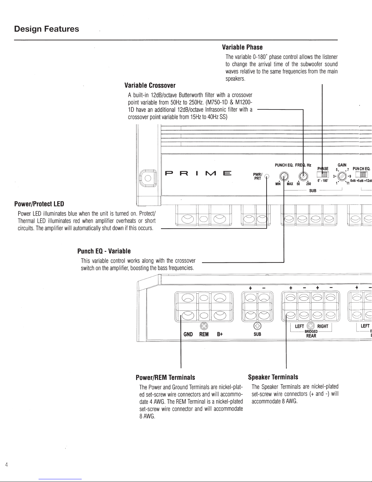
Power/Protect
Power
LED
Thermal
circuits. The
LED
illuminates
LED
illuminates
amplifier
blue
when
red
when
will
automatically
the
unit
amplifier
shut
Variable
is
turned
overheats
down
if
built-in
A
po
int
10
ssover
cro
on
s
thi
Crossover
12dB/octave
variable
have
an
point
(§]
.
Protect/
or
short
occurs.
from
50Hz
additional
variable
p
Butterworth
to
12dB/octave
from
A
e
filter
250Hz. (M750-1
Infrasonic
15Hz
to
I
M
0
Variable
The
variable
to
change
waves
speakers
with a crossover
D &
filter
40Hz
SS)
E
e
Phase
the
relative
.
M1200-
with
a
u
0-180° phase
arrival
time
to
the
same
PUNCH
PWR/
~
PRT
I~
1"-
.0 .
MIN
control
allows
the
listener
of
the
subwoofer
frequencies
EQ.
MAX
FRE
0.
50
from
the
.
Hz
PHSE
_
~-!.
250
SUB
g g g g
sound
main
5 7
l·0.·
1
GAIN
11
PUN
9
od
~
Q
£
CHEQ
<IB+12dl
•
.
Punch
This
variable
switch
EQ -Variable
control
wor
on
the
amplifier, boosting
ks
along
with
the
the
bass
frequencies
111
~--------~
Power/REM
The
Power
ed
set-screw
date 4 AWG. The
set-screw
8AWG.
Terminals
and
Ground
wire
wire
connector
crossover
.
G
e
GND
Terminals
connectors
REM
Terminal
and
0
G
0
e
~
REM
B+
are
nickel-plat-
and
will
accommo-
is a nickel-plated
will
accommodate
+
-
+
a
u
~
@
SUB
Speaker
The
Speaker
set-screw
accommodate 8 AWG.
g
~
Terminals
Terminals
wire
connectors
-
+
-
a a a
g g g
(©)
RIGHT
BRIDGED
REAR
are
nickel-plated
(+and
-)
+
~
I
will
L
- I
LEFT
I
4
Design Features
PUN
[
lB+E
CH EQ.
•n
idB+12dB
I
)g
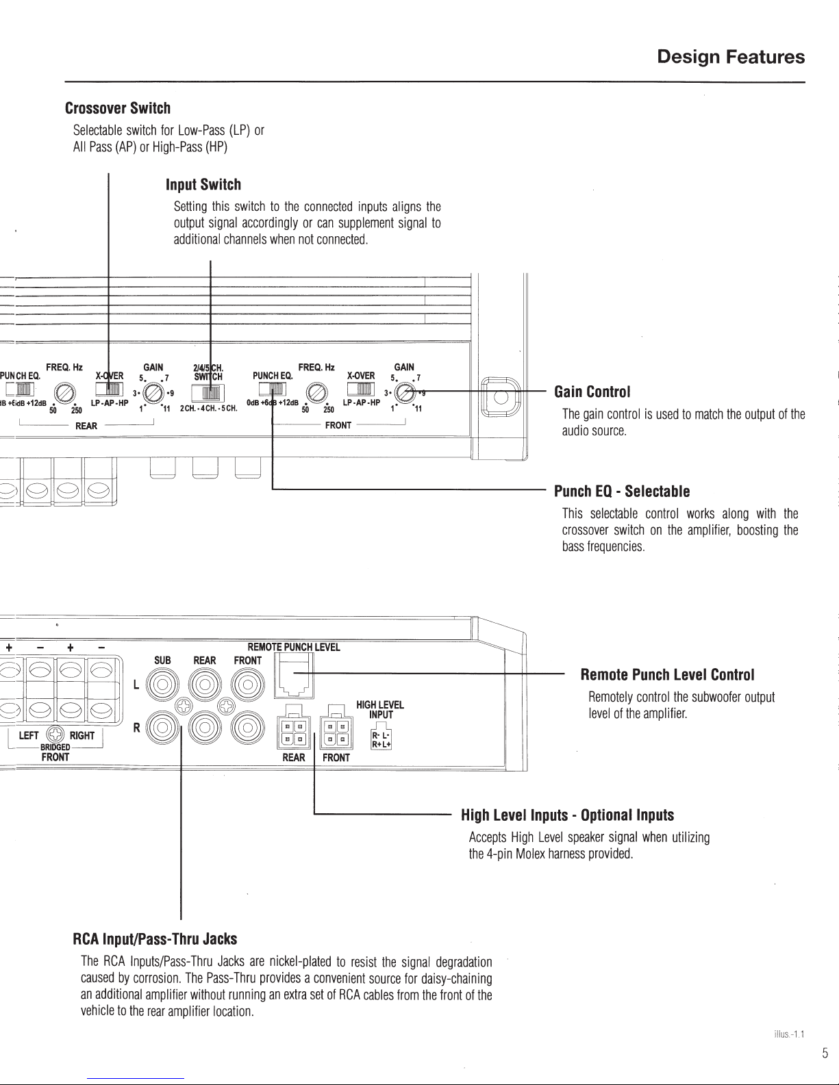
Crossover
Selectable
All
Pass
FREQ.
Hz
0
sO
2•50
LP·AP·HP
REAR
g
g
Switch
switch for
(AP)
or
:.c
WI
X·
ER
s.
c~
3·0·9
1"
Low-Pass
High-Pass
GAIN
• 7
"11
I
(HP)
Input
Switch
Setting
output
additional
2/4/5
SWI
2CH.·4CH.·5CH.
uuu
(LP)
or
this
switch
to
the
connected
signal
accordingly
channels
~H.
CH
PoC
OdB+6j!+12dB • • LP·AP·HP 1•
when
i Q.
1--·----
or
not
FREQ.
0
50
inputs
can
supplement
connected
Hz
.
X-OVER
DDJ
250
FRONT
·--
aligns
signal
GAIN
s.
3•
the
to
-·
.7
..
"11
I
~
~
I
~
Gain
Control
The
gain control
audio
source.
Punch
EO -Selectable
This
selectable
crossover
bass frequ
is
control
switch
encies.
used
on
to
works
the
amplifier,
match
along
the
output
with
boosting
of
the
the
the
+ +
c
~o~
~
;Jggg
L
-
o
r
LEFT ~ RIGHT
BRilGED
FRONT
RCA
The RCA
c
aused
an
vehicle
I
Input/Pass-Thru
additional
SUB
L
~~~
l
l
R
(j~~
REAR
~
Jacks
Inputs/Pass-
by
corro
amplifier
to the
rear
Thru
sio
n.
The
without
amplifier loc
Pass-
FRONT
~
Jacks
Thru
running
ation.
REMOTE
are
nickel-plated
provides a convenient
an
PUNCH
REAR
extra
set
LEVEL
FRONT
to
of
resi
RCA
cables from
st
the
sour
signal
degradation
ce
for
daisy-chaining
the
front
High
Acce
th
e 4-
of the
level
Inputs -Optional
pts
High
Level
pin
Molex
harness
Remote
Remotely control
lev
el
of the
speak
er
signal when
provided.
Punch
amplifier.
Inputs
level
the
subwoofer
utilizing
Control
output
illus.-1.1
5
Installation
Contents
•
Prime
Amplifier
•
Mounting
•
Allen
•
Punch
Installation
The
following
•
Fuse-holder
specifications
•
Volt/Ohm
•
Wire
•
Wire
•
Wire
•
#2
•
Battery
This
ing
your
routes
system,
adjustments.
If
you
a
qualified
Hardware
Wrench
Level
Control
Considerations
is a list
and
for
Meter
strippers
crimpers
cutters
Phillips
screwdriver
post
wrench
section
focuses
new
amplifier.
will
save
installation
be
sure
that
feel
unsure
about
technician
.6. CAUTION
Lt.
CAUTION
1.
Be
sure
to
carefully read
attempting
2.
For
beginning
3.
For
your
4.
Route
current
safety,
the
easier
assembly,
unit
in
all
of
wires.
to
install
disconnect
place
the
of
tools
fuse. (See
fuse
rating)
on
some
Pre-planning
time. When
each
component
installing
.
Before
ative
fire
Before
simple
the
unit.
the
installation
we
suggest
.
RCA
cables
needed
for
of
the
vehicle
your
will
this
system
installation,
(-)terminal
and/or
possible
beginning
rules
and
understand
negative
.
you
close
•
4-pin
Molex
Connector
equipped)
•
Installation & Operation
Manual
installation:
•
Hand
held
drill
w/assorted bits
•
Assorted
•
Adequate
Wire
•
Adequate
Turn-on
•
Adequate
Grounding
system
deciding
be
:
lead
run all
together
connectors
Length-Red
Length-Remote
Wire
Length-Black
Wire
considerations
layout
and
on
the
layout
easily accessible
yourself,
disconnect
to
any
have
prevent
damage
injury.
installation,
the
instructions
from
the
wires
prior
and
away
the
battery
from
it
battery
follow
to
(if
Power
for
install-
best
wiring
of
your
new
for
making
installed
neg-
to
the
unit,
these
before
prior
mounting
any
high
by
to
6.
Think
before
lines,
brake
working
7.
Never
run
vehic
le
8.
Avoid
plastic
the
firewall.
9.
ALWAYS
proper
power
wire
10.
When
grounding
the
metal
connections
to
metal
Seatbelt
Mounting
To
1"
proper
Trunk
Mounting
ing
provide
Passenger
Mounting
you
are
have
A--
~
Battery
Amplifiers
system.
to ens
increased
in
Series
be
s
uggest the
Locations
ensure
(2.54cm)
cooling.
Mounting
the
of
the
amplifier.
the
the
provide a sufficient
going
to
at
least
CAUTION
and
will
We
ure
that
load
good
condition
amplifier
reduced
you
drill!
or
hydraulic
on
any
vehicle.
wires
underneath
provides
running
grommets
fusing.
optimal
best
Compartment
the
best
wires
to
protect
protect
the
battery
Install
the
within
18"
to
the
to
ensure a good, clean
should
be
that
is
welded
bolts
should
performance, mount
of
air
gap
around
amplifier
amplifier
mount
1" (2.
Mounting
cooling
in
the
54cm)
vertically
of
the
amount
amplifier
of
Charging
put
an
increased
recommend
the
of
without
slightly.
use
of a heavy
checking
electrical system
your
stereo
should
proble
To
maximize
Be
careful
not
to
cut
lines,
vacuum
the
protection.
over
or
any
and
appropriate
(45.7
em)
chassis
as
short
to
the
main
never
the
or
the
amplifier
the
amplifier.
Mounting
passenger
of
air
under
air
gap
Never
mount
ment.
Mounting
partment
load
system. Stock electrical
be
able to
ms, although
the performance
duty
battery
lines
vehicle. Running
through
be
sharp
wires
routed
electrical
fuse
holder
of
the
battery
of
the
vehicle,
ground
as
possible
body,
used
for
the
amplifier's
inverted
around
will
on
your
will
on
compartment
for
the
amplifier
the
seat
the
this
unit
the
void
your
the
vehicle's
alternator
has
enough
handle
the
battery
and
an ene
or
drill
into
or
electrical
the
edges.
through
metal,
system
from
and
fuse
terminal.
scrape
connection.
and
always
or
chassis, of
connecting
amplifier
heat
sink
provide
the
floor
will
to
cool
of
the
vehicle,
amplifier
's
in
the
unit
in
warranty.
battery
and
capacity
systems
extra
load
and
of
your
rgy
storage
engine
the
battery
alternator
gas
tanks,
wiring
wires
inside
Use
rubber
especially
damage
on
the+
all
paint
Grounding
be
connected
the
vehicle
to
ground.
with
at
to
provide
adequate
of
the
trunk
work
as
long
itself.
you
heats
ink.
compart-
engine
and
charging
condition
to
handle
which
of
any
life
amplifier,
capacitor.
fuel
when
the
or
with
12V
from
.
least
cool-
will
as
If
you
must
com-
the
are
Prime
can
we
5.
Use
high
quality
connectors
signal
or
power
loss.
6
for a reliable
installation
and
to
minimize
 Loading...