

Page 1
A
I
R1-HD4-9813
E
Serial
Number:
____
_
Date
of
Purchase:
____
_
Page 2
Dear
Customer,
Congratulations
products.
tion
years
procedures,
music
For
Fosgate
as
Institute
original
Great
when
100%
installation.
speaker
your
To
your
jackets.
Visit
www.
or,
countries,
At
Rockford
at
its
best,
and
of
engineering
we
with
all
the
maximum
we
provide
product
it
new
add
Rockford
our
performance
product
specialized
(RTTI).
carton
and
comes
authentic
Rockford
wire
to
system
the
finishing
web
site
for
to
accessories,
rockfordfosgate.
in
the
U.S.
call1-800-669-9899
call
+001-480-967
on
your
purchase
Fosgate
we
are
expertise,
have
created a wide
clarity
and
installed
Please
read
possible
competent
your
system.
installation
Fosgate
power
wire
deserves
touch
tor
the
we
pleased
hand
richness
we
recommend
by
an
Authorized
training
your
future
installations
Make
accessories
has
and
battery
nothing
to
your
which
latest
information
com
-3565
of
the
world's
are
fanatics
you
chose
craftsmanship
range
of
you
deserve.
you
Rockford
through
warranty
use.
everything
new
include
Rockford
and
are
sure
that
from
connectors.
but
the
best.
Rockford
everything
on
or
FAX
1-800-398-3985.
or
FAX
+001-480-966-3983.
finest
about
musical
our
product.
and
products
have
your
Fosgate
Technical
retain
your
only a piece
your
installer
Rockford
from
RCA
Insist
Fosgate
from
all
Rockford
brand
of
reproduc-
Through
critical
that
reproduce
new
Dealer,
receipt
of
the
is
Fosgate
cables
on
it!
image
T-shirts
products;
For
car
audio
testing
Rockford
Training
and
puzzle
using
in
your
and
After
all,
order
to
all
other
If,
after
reading
uct,
we
recommend
further
assistance,
have
your
serial
when
you
call.
Safety
This
symbol
to
alert
the
instructions.
will
result
This
symbol
alert
the
user
instructions.
can
result
•
To
prevent
instructions
a
headache.
your
with
user
Failure
in
severe
with
Failure
in
injury
to
injury
manual,
that
you
you
can
number,
model
"WARNING"
to
the
presence
to
heed
injury
"CAUTION"
the
presence
to
heed
or
unit
and
damage
in
this
manual.
you
still
see
your
call
us
direct
number
is
of
the
instructions
or
death.
is
intended
of
the
instructions
damage.
to
We
have
questions
Rockford
at
1-800-669-9899.
and
intended
important
to
important
the
unit,
want
you
to
regarding
Fosgate
date
ili
ili
please
dealer.
of
purchase
I.\
WARNING
I.\
CAUTION
read
enjoy
this
system,
and
this
prod-
If
you
need
Be
sure
available
follow
not
to
the
get
Table
of
Content
8-10
11-13
14-15
2
Introduction
3
Specifications
4-5
Design
Wiring
6
7
Installation
Installation
Ultra
Electra
Street
Tri
Installation
Road
Road
Installation
Warranty
16
Diagram
Classic®
Glide®
All
Models
Features
Considerations
Glide®
Glide®
Glide®
Glide
Ultra®
•
If
you
feel
by a qualified
•
Before
installation,
prevent
damage
unsure
Rockford
to
about
installing
Fosgate
disconnect
the
unit,
this
technician.
the
fire
and/or
system
battery
possible
yourself,
negative
injury.
have
(-)
terminal
it
installed
to
Page 3
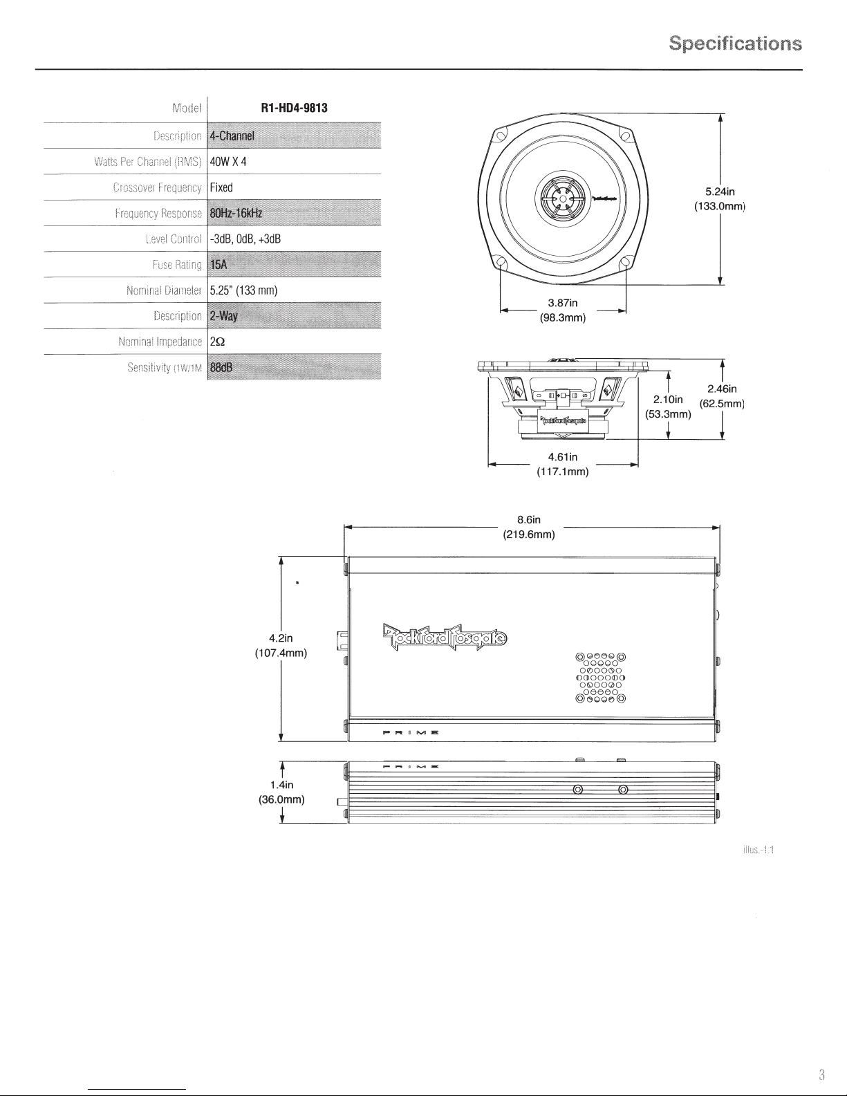
Specifications
5.24in
(133.0mm)
Sensi!iv:ty
i1W/1M
.
.2in 4
(107 .4mm)
L
~
~
p R
~
~
4.61in
(117.1mm)
8 6in
(219.6mm)
0G0G0
@
O@G
0@
OQ:l00(Sl0
00>0001[)0
01»00(2)0
@oe?oeGe
~o@
lliiiii:
~
t
1.4in
(36.0mm)
!
i:l
us.
! .1
3
Page 4
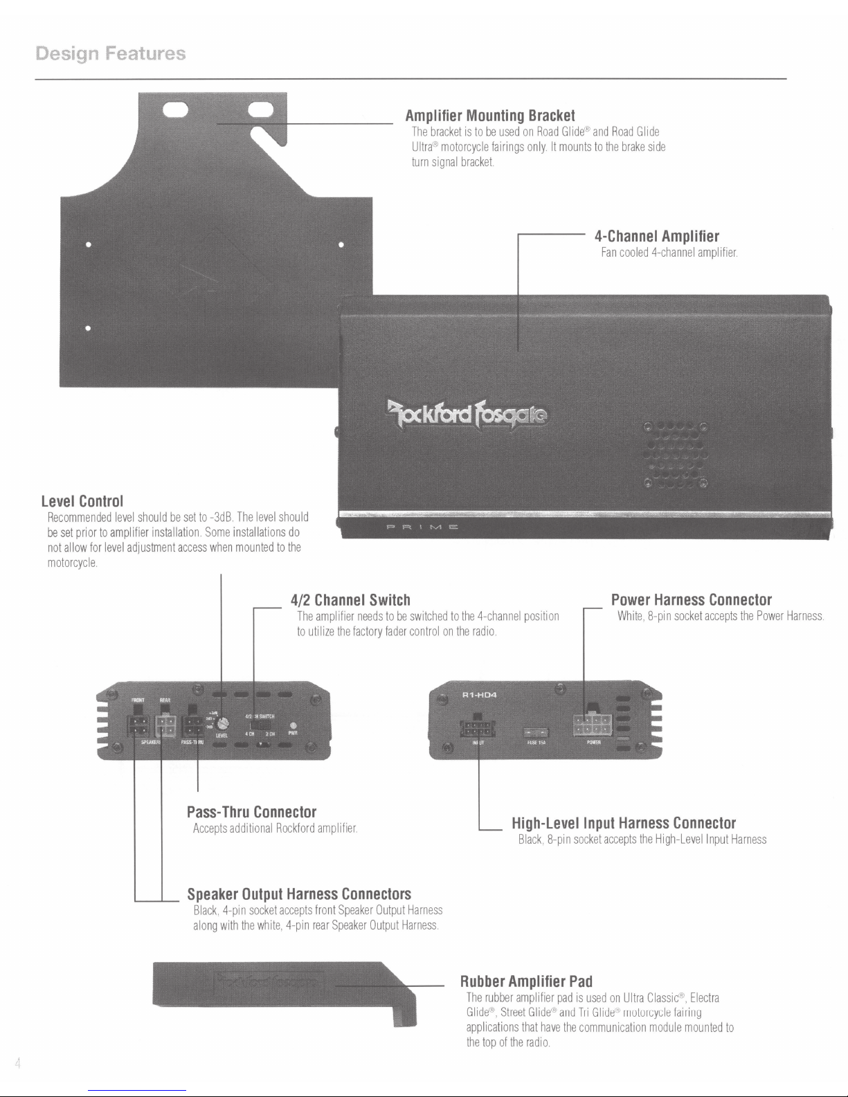
Design Features
level
Control
Recommended
be
set
prior
to
amplifier
not
allow
for
level
motorcycle
.
level
should
installation. Some
adjustment
be
set
access
to
-3d
when
B.
The
level
installations
mounted
should
do
to
the
Amplifier
The
Ultra® motorcycle
turn
bracket
signal
bracket.
Mounting
is
to
be
used
fairings
Bracket
on
Road
Glide® and
only. It
mounts
Road
Glide
to
the
brake
side
4-Channel
Fan
cooled
4-channel
Amplifier
amplifier
.
Pass-
Thru
Accepts
._____....____
Speaker
Black, 4-pin
along
with
Connector
additional
Output
socket
the
white, 4-pin
4/2
Channel
The
amp!
to
utilize
Rockford
amplifier
Harness
accepts
front
rear
Switch
ifier
needs
to
be
the
factory
fader
.
Connectors
Speaker
Output
Speaker
Output
switched
control
Harness
Harness
to
the
4-chan
on
the
radio
~
R1-H04
: . .
!HI
lit
.
Rubber
The
rubber
Glide
applications
the
top
nel
position
.
f1JS!
High-Level
Black, S-pin
Amplifier
amplifier
®,
Street
Glide® and
that
of
the
radio
15A
have
.
.
Pad
pad
the
Power
White, S-pin
LiiB
PQWEA
Input
socket
is
used
Tri
Glide® motorcycle
communication
~
Harness
accepts
the
on
Ultra
Harness
socket
~
Connector
High-Level
Classic
®,
fairing
module
mounted
Connector
accepts
input
Harness
Electra
to
the
Power
Harness
.
Page 5
Design Features
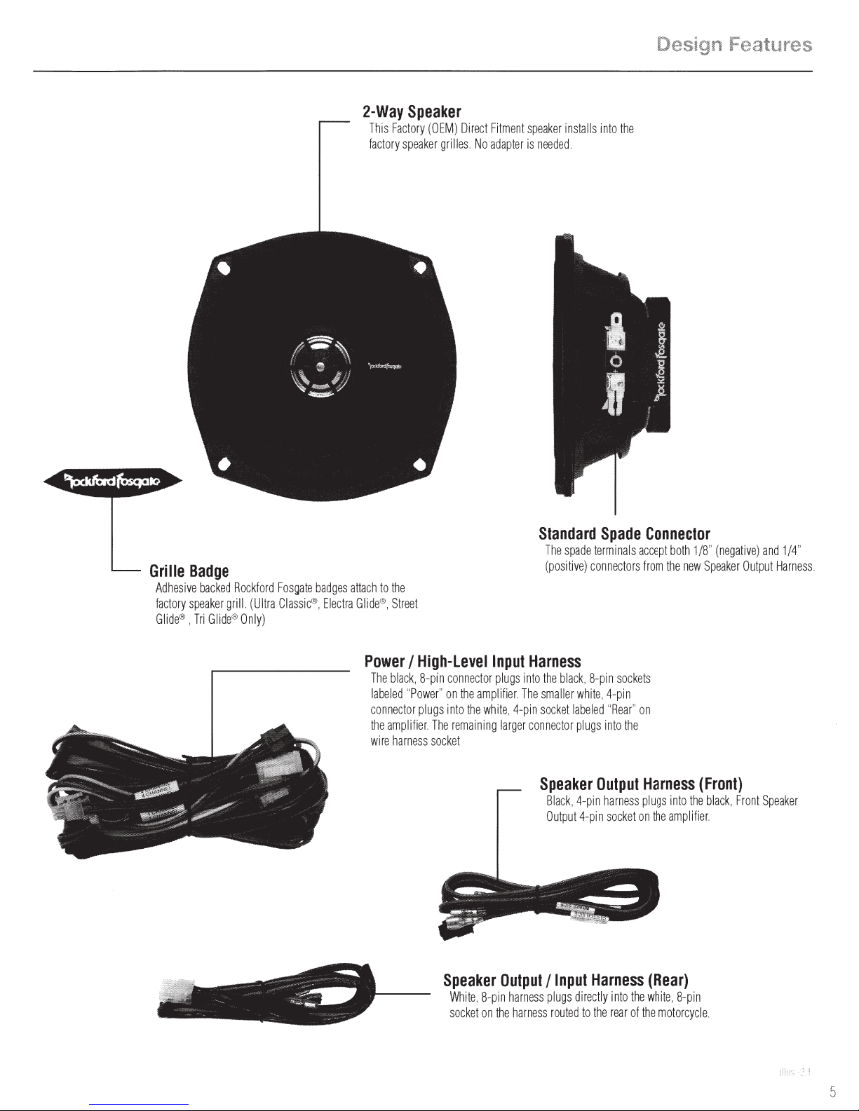
2-Way
Th
is
Fac
factory
Speaker
tory
(OEM)
speaker
grilles
Direct Fitme
No adap
nt
speaker
ter is
need
installs in
ed.
to
the
Grille
Badge
Adhesive bac
fa
ctory spea
G
lide®,
Tri
ked
Rockfo
ker grill (
Glid
e® O
rd Fosgate badges attach to
Ultr
a Cl
assic®, Electra G
nly
)
the
lid
e®, Stre
et
Power I High-Levellnput
The blac
k, 8-p
l
abeled
connec
the amp
wir
e harness
"Power"
tor pl
ugs
lifi
er The rema
socket
in connect
or plugs into
on the amplif
int
o the
whit
ini
ng
Harness
ier
The smaller
e, 4-pin socket label
larger c
Standard
The spade terminals
(pos
the black, 8-
onnector plugs into
Speaker
Bl
ack
tp
Ou
itiv
e) con
whit
, 4-pin h
ut
4-p
Spade
necto
pin
e, 4-pin
ed
"Rea
Output
arness plugs
in soc
Connector
acc
ept
rs from the n
socke
ts
r"
on
the
Harness
ket on the a
both 1/8"
ew
Speake
(Front)
into the bla
mplifi
er
(nega
ck, Fro
tiv
e)
r Outp
nt
and
1/4"
ut Harn
Spea
ker
ess
Speaker
White, 8-pin harness
soc
Output I Input
ket on t
he harn
plu
gs
ess routed
Harness
directly into the white,
to t
he rea
(Rear)
r of the motorcycle
8-p
in
Page 6
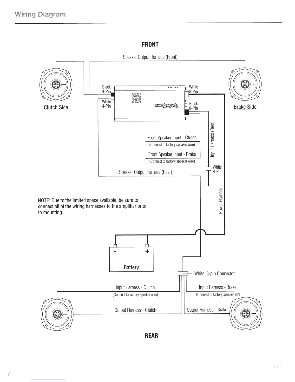
ing Diagram
Wir
FRONT
Clutch
NOTE:
connect
mounting.
to
Due
all
Side
the
to
the
of
limited
wiring
available,
space
harnesses
to
be
the
Speaker
Output
ker
a
pe
S
sure
amplifier
Output
to
prior
Harness
Speaker
ront
F
(Conn
Front
nn
Co
(
rnes
Ha
(Front)
fa
to
t
ec
Speak
fact
to
t
ec
(Rear)
s
cto
er
put
In
ry s
Input
spea
ry
o
Clutch
-
peaker
Brake
-
ker
Whi
Pin
8-
Black
8-Pin
wire)
e)
wir
te
::<;
Q)
fS
(/)
(/)
Q)
E
I
"'
Whit
Pin
4-
e
(/)
(/)
Q)
c:
::<;
I
Brake
Side
Input
nec
n
(Co
Output
Battery
ess
rn
Ha
ry
acto
to f
t
ess
Harn
+
tc
lu
- C
r w
speake
ch
lut
- C
REAR
h
tor
ec
nn
Co
in
8-p
e,
Whit
ake
Br
ss-
Harne
t
Inpu
e)
ir
r w
speake
ory
fact
to
t
nec
n
Out
(Co
Brake
s -
es
Harn
ut
p
e)
ir
Page 7

Contents
•
4-Channel
•
Amplifier
•
2-Way
•
Power
•
High-Level
•
Speaker
Installation
The
following
•
Wrenches 1 Sockets3/8",
•
Allen
•
Torx-
•
#2
Mounting
Speakers
Harness
Output
1/2",
Wrench
T10,
Phillips
Amplifier
Input
Tools
is a list
10mm
T25
Screw
Bracket
(2
Pair)
Harness
Harness
of
suggested
7/16",
1/8",
5/32"
Driver
•
•
•
•
•
tools
•
•
•
Mounting
Zip
Ties
Velcro
Pads
Grille
Badges
Rubber
Amplifier
needed
for
Small
Flat
Wire
Cutters
Scissors
Screws
Pad
installation:
Blade
Screw
Driver
Installation
This
section
focuses
audio
kit.
This
styles
offered
from
1998
to
Glide®,
Road
NOTE:
This
If
you
feel
unsure
a
qualified
Lt.
Lt.
•
•
•
technician.
CAUTION
CAUTION
Be
sure
to
attempting
Consult
information.
options
This
(OEM)
your
and
motorcycle
4-speaker
Considerations
on
some
considerations
manual
will
illustrate
by
Harley-Davidson®
2013.
(Ultra
Classic®,
Glide®
and
Road
Glide
kit
will
not
work
on
about
installing
carefully
to
install
this
motorcycle's
Models
may
aftermarket
audio
setup.
this
Before
installation,
ative
(-)
fire
and/or
Before
beginning
simple
rules:
read
and
motorcycle
service
differ
accessories
kit
is a complete
for
the
installation
from
the
Electra
Ultra®.)
CVO™
models.
system
terminal
from
to
possible
understand
audio
manual
year
added.
installing
of
two
production
Glide®,
yourself,
disconnect
prevent
injury.
any
kit.
to
replacement
Street
have
damage
installation,
the
instructions
for
year
depending
your
motorcycle
different
years
Glide®,
it
installed
the
battery
to
follow
model
on
to
the
fairing
ranging
Tri
by
neg-
the
unit,
these
before
specific
factory
factory
•
With
the
addition
system
is
in
•
Utilize a blanket
or
any
other
the
fairing.
•
Visit
rockfordfosgate.com
videos
and
of
proper
or
item
that
product
an
amplifier,
working
fender
information.
cover
may
order.
be
accidentally
for
be
to
protect
more
sure
that
your
the
front
be
dropped
comprehensive
current
fender
while
charging
from
tools
removing
installation
Page 8

Installation
Ultra
Glide®
Tri
1 -
Step
begin
To
remove
Classic®,
models.
Fairing
with
the
Removal
remove
,
windshield.
Electra
top
the
Glide®,
below
bolts
Street
the
Glide®
windshield
and
and
need
will
You
Speaker
2 -
fairing
the
the
to
take
Remove
completely
Step
After
terminals.
grille
disconnect
to
the
removed,
is
the
fairing.
the
off
fairing
Removal
unplug
screws
Remove
each
harness
motorcycle
the
of
the
secure
that
speaker
from
wires
the
out
headlight
the
.
both
from
factory
the
of
to
speaker
speaker
factory
and
grille.
remove
aside,
the
set
fairing.
This
will
windshield
the
have
you
Once
of
inside
the
screws
the
Q
v
on
front
fairing.
the
allow
remaining
remove
to
you
NOTE:
and
clutch
3 -
Step
the
Take
Rockford
new
sure
Be
brake
Speaker
factory
keep
to
speakers.
side
Installation
speaker
speaker
to
track
grille
the
wires
the
of
assembly
factory
grille
are
that
carefully
and
.
plugged
attach
into
the
the
Page 9

Installation
NOTE:
You
can
insert
and
use a flat
onto
the
the
terminals
Reattach
bladed
speaker
up.
the
speaker
for a tight
Step 4-Amplifier
All
of
the
wiring
harnesses
the
one
side
screwdriver
fit.
Be
and
grille
assembly
Pre-Wire
are
color
of
the
or
pry
sure
coded
speaker
bar
to
to
orientate
to
the
for
into
gently
the
fairing.
ease
of
the
assembly
pry
the
grille
speaker
with
installation.
Step 5 -Amplifier
Without
Using
the
of
NOTE:
be
provides
Communication
the
supplied
radio
and
the
radio
for
When
applied
close
adequate
Velcro
the
bottom
proper
applying
to
the
clearance
Mounting
Module
pad,
cut
of
the
amplifier.
adhesion.
the
Velcro
gauge
cluster
for
the
it
to
the
fairing
in
half
top
side
and
Be
sure
of
so
when
the
apply
to
to
clean
the
radio,
installed
reinstalled.
the
top
the
top
it
needs
amplifier
of
to
NOTE:
Due
to
the
the
wiring
harnesses
recommended
setting
Refer
to
is
-3dB.
wiring
setting
diagram
connections
limited
to
the
the
on
space
available,
amplifier
Level
at
Page 6 for
prior
this
time.
harness
be
sure
to
to
mounting.
The
recommended
and
wire
connect
It
is
also
all
of
With
Communication
Models
supplied
equipped
rubber
with
foot
Module
the
communication
to
the
bottom
side
module,
of
the
installing
amplifier
the
is
required.
Page 10

Installation
Velcro
the
Attach
underside
Once
of
amplifier
the
on
amplifier.
the
is
the
of
top
mounted,
now
module
wire
communication
can
you
up
the
the
to
and
speakers.
Remote
7 -
Step
speakers
the
After
the
plug
to
I
amp
the
the
When
may
zip
be
connected
for
Unplug
Then
NOTE:
which
should
Wire
are
cigarette
the
ifier.
existing
orange
routing
damage
cause
up
tied
the
wired,
ighter.
I
wire
and
lighter
onto
wires,
the
to
out
cigarette
your
orange
This
the
be
wiring
the
of
will
wire
the
is
and
wire
avoid
to
lighter
cigarette
sure
harnesses.
components.
of
way
need
remote
into
plug
terminal.
sharp
Any
be
to
power
the
edges
extra
turn-on
harness.
wiring
Fairing
6 -
Step
factory
the
Take
you
Input
can
speaker
High-Level
Now
Rockford
Speaker
speaker
Harness.
the
plug
terminals.
wires
new
Wiring
plug
and
are
These
Speaker
Output
them
labeled
Harness
directly
and
clutch
onto
to
in
brake
the
the
new
side.
Step
Proceed
to
instructions.
8
on
page
14
for
continued
installation
negative
for
1/8"
the
sizing
utilize
easy
for
connections.
terminals
The
NOTE:
positive(+)
for
10
(-)and
the
1/4"
Page 11

Road
1 -
Step
Leaving
screws.
Glide®
Removal
windshield
the
and
Road
place,
in
Glide
remove
Ultra®
inner
six
the
models.
fairing
fairing
the
Pull
fairing
the
Speaker
2 -
Step
fairing
the
After
terminals.
grille.
the
toward
mounts.
Remove
Unplug
removed,
is
the
front
the
headlight
Removal
unplug
that
screws
the
of
secure
and
bike
harness
wires
the
the
Installation
it
release
to
up
aside.
fairing
set
and
speaker
both
from
speaker
factory
from
from
screws
the
After
the
unbolt
to
Some
NOTE:
completely
accessory
factory
removed,
are
signal
turn
signal
turn
removed.
This
styles
your
use
brackets.
varies
stay
depending
brackets
or
socket
attached
and
aftermarket
on
ratcheting
some
wrench
can
and
be
Be
NOTE:
and
clutch
Remove
each
sure
brake
speaker
to
side
keep
the
of
track
speakers.
factory
the
of
out
wires
gri
that
lie.
plugged
are
into
the
Page 12
Installation
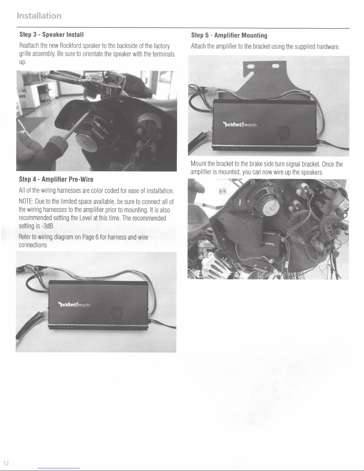
Step
3 -
Speaker
Install
Step
5
-Amplifier
Mounting
Reattach
grille
the
new
assembly.
up.
Step
4 -
Amplifier
All
of
the
wiring
NOTE:
Due
to
the
the
wiring
harnesses
recommended
setting
is
-3dB.
setting
Rockford
Be
sure
speaker
to
orientate
Pre-Wire
harnesses
limited
to
the
the
are
space
amplifier
Level
to
the
the
color
coded
available,
prior
at
this
time.
backside
speaker
with
for
ease
be
sure
to
mounting.
The
recommended
of
the
the
of
installation.
to
connect
It
factory
terminals
all
of
is
also
Attach
the
Mount
the
amplifier
amplifier
bracket
is
mounted,
to
to
the
the
brake
you
bracket
side
can
now
using
turn
wire
the
supplied
signal
up
the
hardware.
bracket.
Once
speakers.
the
Refer
to
wiring
connections
diagram
on
Page
6
for
harness
and
wire
12
Page 13

Step
6 -
Fairing
Take
the
factory
speaker
High-Levellnput
Now
you
can
plug
Rockford
NOTE:
for
speaker
The
terminals
positive(+)
sizing
Speaker
wires
Harness.
the
new
These
Speaker
terminals.
utilize
for
easy
Wiring
and
plug
are
labeled
Output
the
1/8"
for
connections.
them
directly
clutch
Harness
negative(-)
in
and
onto
and
to
the
brake
the
the
1/4"
Installation
new
side.
Step
7 -
Remote
After
the
speakers
connected
for
Unplug
Then
NOTE:
which
should
the
amplifier.
the
plug
When
may
be
to
the
zip
are
the
cigarette
existing
orange
routing
cause
damage
tied
up
Wire
wired,
I
ighter.
cigarette
wire
onto
your
wires,
t<J
and
out
the
orange
This
lighter
the
be
the
wiring
of
the
wire
is
the
wire
and
cigarette
sure
to
avoid
harnesses.
way
of
components.
will
need
remote
plug
into
lighter
terminal.
sharp
Any
to
be
power
the
edges
extra
turn-on
harness.
wiring
Page 14

Installation
All
Models
Step
8 -
Routing
Pass
the
power
harness
fairing
and
route
next
Power
and
to
the
Harness I Rear
rear
speaker
factory
wiring
harness
harness.
Speaker
through
Harness
the
.Lh
WARNING
Step
10
-Gas
Tank
Once
all
wires
are
the
tank
console.
communication
wire
The
gas
the
console
prevent
fire
hazard.
Console
routed
down
Remember
and
the
to
gas
cap
should
is
off
put
any
gas
fumes
Installation
the
top
side
of
reconnect
cap.
the
not
be
left
off.
Once
the
cap
back
on
creating a potential
the
tank,
reinstall
vent
line,
the
to
Routing
recommended.
tight
Step 9 -Gas
Remove
underneath
and
the
new
wire
Be
fit.
Tank
the
gas
tank
of
it.
communication
harness
sure
Console
console
You
will
wires
to
zip
need
(if
equipped).
along
with
tie
the
harness
Removal
so
you
can
to
remove
the
factory
together
route
the
gas
harness
for a clean,
the
harness(s)
cap,
vent
is
tube
Step
11 -Rear
Unscrew
speaker.
and
the
Disconnect
remove
Speaker
speaker
speaker.
grilles
the
Removal
from
factory
the
rear
wiring
pods
from
and
the
speaker
remove
factory
terminal
14
Page 15
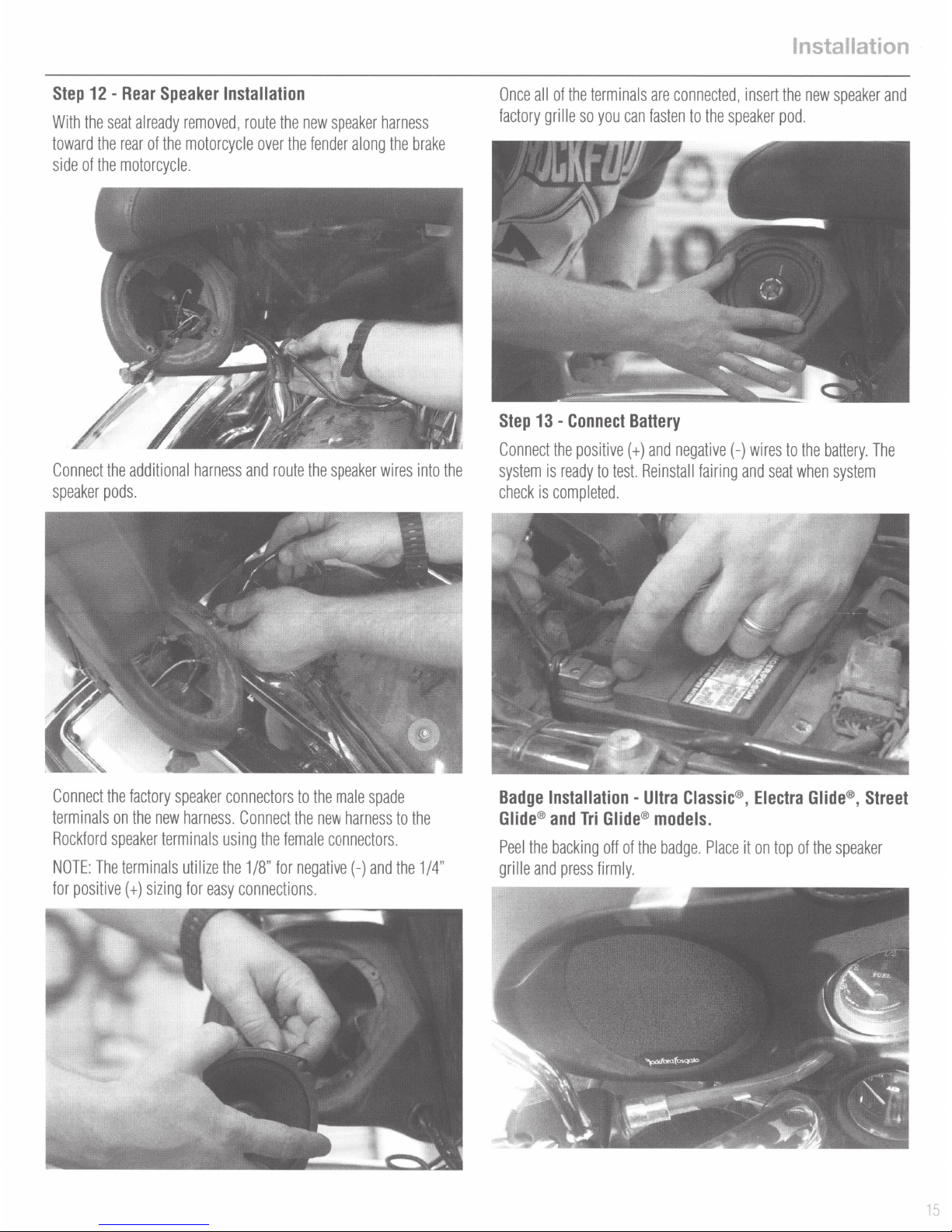
Step
12-
With
the
toward
side
of
Rear
seat
already
the
rear
of
the
motorcycle.
Speaker
removed,
the
motorcycle
Installation
route
the
new
over
the
speaker
fender
harness
along
the
brake
Once
all
factory
Step
13
of
the
grille
so
-
Connect
terminals
you
can
Battery
are
connected,
fasten
to
the
speaker
insert
Installation
the
new
speaker
pod.
and
Connect
speaker
Connect
terminals
Rockford
NOTE:
for
the
pods.
the
The
positive
additional
factory
on
the
new
speaker
terminals
terminals
(
+)
sizing
harness
speaker
harness.
using
utilize
the
for
easy
and
route
connectors
Connect
1/8"
connections.
the
for
the
female
to
negative(-)
the
speaker
the
male
new
harness
connectors.
wires
spade
to
and
the
into
the
1/4"
the
Connect
system
check
Badge
Glide®
Peel
grille
is
is
Installationand
the
and
the
positive
ready
to
test.
completed.
Tri
Glide®
backing
press
off
of
firmly.
(
+)
and
Reinstall
Ultra
models.
the
badge.
negative
(-)
fairing
Classic®,
Place
wires
and
seat
Electra
it
on
top
to
the
when
Glide®,
of
the
battery.
system
Street
speaker
The
15
Page 16

Warranty
Rockford
length
POWER
BMW
All
Any
What
This
possessions.
tor
Who
This
to
purchase.
Products
What
1.
2.
3.
4.
5.
6.
7.
Corporation
of
Amplifiers-
®
Direct
other
products
Factory
is
Covered
warranty
and
not
is
Covered
warranty
receive
service,
found
is
Not
Damage
Any
cost
Service
Any
product
Subsequent
Any
product
Any
product
Warranty
2
Fit
Speakers-
- 1
Year
Refurbished
applies
only
Product
by
purchased
Rockford
covers
only
the
purchaser
to
be
defective
Covered
caused
by
or
expense
performed
which
damage
purchased
not
purchased
offers
a
limited
Years
2
Years
Product-
to
Corporation.
the
accident,
related
by
anyone
has
to
Rockford
by
original
must
during
abuse,
to
the
other
had
the
other
components
outside
from
90
serial
warranty
days
(receipt
Fosgate
consumers
purchaser
provide
the
removal
the
an
products
from
Rockford
warranty
improper
or
than
Rockford
number
.
U.S.
Authorized
on
Rockford
required)
sold
to
consumers
an
Authorized
of
Rockford
period
operations,water,
reinstallation
defaced,
Rockford
with
will
or
an
Authorized
altered,
product
a
copy
be
repaired
of
Fosgate
Fosgate
Rockford
purchased
of
the
or
theft,
shipping.
product.
Rockford
or
removed
Dealer.
products
by
Authorized
Fosgate
from
receipt
stating
replaced
Fosgate
.
on
the
Rockford
Dealer
in
an
Authorized
the
customer
(with
a
product
Service
following
Fosgate
another
country
Rockford
deemed
Center.
terms:
Dealers
name,
in
are
covered
Fosgate
dealer
name,
to
be
equivalent)
the
United
only
Dealer
product
in
by
the
at
Rockford
States
of
America
that
country's
United
States.
purchased
's
discretion.
Distribu-
In
and
date
or
its
order
of
limit
on
Any
implied
above
Rockford
How
to
Contact
tomer
product
EU
Warranty
This
product
Implied
warranties
.
Some
Fosgate
Obtain
the
Authorized
Service.
to
Rockford.
meets
Warranties
states
do
any
Service
You
must
the
including
not
allow
other
liability
Rockford
obtain
current
warranties
limitations
in
connection
Fosgate
an
RA#
EU
warranty
of
fitness
on
the
length
with
Dealer
you
purchased
(Return
Authorization
requirements,
for
the
use
of
sale
see
an
and
merchantability
implied
warranty,
of
the
product.
this
product
number)
your
to
Authorized
from.
return
dealer
are
so
If
any
limited
this
limitation
you
need
product
for
details.
in
duration
may
further
to
Rockford
to
the
not
apply
assistance
Fosgate.
period
.
No
,
call1
of
person
-
800
You
are
the
express
is
authorized
-
669
-
9899
responsible
warranty
to
assume
for
Rockford
for
shipment
set
forth
for
Cus
of
-
16
Page 17

600
South
Direct:
Rockford
(480)
967-3565
Drive
•
Tempe,
•
Arizona
Toll
Free:
85281
(800)
United
669-9899
States
ROC
KFO
R
DFOSGATE.
COM
 Loading...