

Rockford Fosgate Power T15kW Installation & Operation Manual


2
INTRODUCTION
A message from the design engineer:
Dear Fanatic:
Congratulations on your decision to purchase the most powerful and advanced mobile audio amplifier available today.With proper setup and
care it should bring you enjoyment for many years to come. I hope you enjoy it and the way it reproduces music as much as I have enjoyed
creating for you. Like many new technologies, this amplifier has received praise from some and skepticism from others, one thing is for certain:
This amplifier needs to be heard to be believed. Sit down, hang on and LISTEN.
Sincerely, Anthony D'Amore
Dear Customer,
Congratulations on your purchase of the world's finest brand of car audio amplifiers.At Rockford Fosgate we are fanatics about musical
reproduction at its best, and we are pleased you chose our product.Through years of engineering expertise, hand craftsmanship and critical
testing procedures, we have created a wide range of products that reproduce music with all the clarity and richness you deserve.
For maximum performance we recommend you have your new Rockford Fosgate product installed by an Authorized Rockford Fosgate Dealer,
as we provide specialized training through Rockford Technical Training Institute (RTTI). Please read your warranty and retain your receipt and
original carton for possible future use.
Great product and competent installations are only a piece of the puzzle when it comes to your system. Make sure that your installer is using
100% authentic installation accessories from Connecting Punch in your installation. Connecting Punch has everything from RCA cables and
speaker wire to Power line and battery connectors. Insist on it! After all, your new system deserves nothing but the best.
To get a free brochure on Rockford Fosgate products and Rockford accessories, visit our web site at: www.rockfordfosgate.com
or, in the U.S. call 1-800-669-9899 or FAX 1-800-398-3985. For all other countries, call +001-480-967-3565 or FAX +001-480-967-8132.
If, after reading your manual, you still have questions regarding this product, we recommend that you see your Rockford Fosgate dealer. If you
need further assistance, you can call us direct at 1-800-669-9899. Be sure to have your serial number, model number and date of purchase
available when you call.
The serial number can be found on the outside of the box. Please record it in the space provided below as your permanent record.This will
serve as verification of your factory warranty and may become useful in recovering your unit if it is ever stolen.
Serial Number:
Model Number: POWER T15kW
TABLE OF CONTENTS
Introduction. . . . . . . . . . . . . . . . . . . . . . . . . . . . . . . . . . . 2
Safety Instructions . . . . . . . . . . . . . . . . . . . . . . . . . . . . . 3
Design Features . . . . . . . . . . . . . . . . . . . . . . . . . . . . . . 4-6
Hybrid Technology . . . . . . . . . . . . . . . . . . . . . . . . . . . . . . . . 4
Installation . . . . . . . . . . . . . . . . . . . . . . . . . . . . . . . . . 7-12
Installation Considerations. . . . . . . . . . . . . . . . . . . . . . . . . . 7
Mounting Locations . . . . . . . . . . . . . . . . . . . . . . . . . . . . . . . 7
Wiring the System . . . . . . . . . . . . . . . . . . . . . . . . . . . . . . . . 8
Example System Configurations. . . . . . . . . . . . . . . . . . . . . . 9
Operation . . . . . . . . . . . . . . . . . . . . . . . . . . . . . . . . . . . 13
Adjusting Gain . . . . . . . . . . . . . . . . . . . . . . . . . . . . . . . . . . 16
Adjusting Crossover Frequency. . . . . . . . . . . . . . . . . . . . . 16
Infrasonic Filter. . . . . . . . . . . . . . . . . . . . . . . . . . . . . . . . . . 16
Channel Link . . . . . . . . . . . . . . . . . . . . . . . . . . . . . . . . . . . . 17
Troubleshooting . . . . . . . . . . . . . . . . . . . . . . . . . . . . . . 14
Specifications. . . . . . . . . . . . . . . . . . . . . . . . . . . . . . . . . 15
Limited Warranty Information . . . . . . . . . . . Back Page
GETTING STARTED
Welcome to Rockford Fosgate! This manual is designed to provide information for the owner, salesperson and installer. For those
of you who want quick information on how to install this product, please turn to the Installation Section of this manual. Other
information can be located by using the Table of Contents.We, at Rockford Fosgate, have worked very hard to make sure all the
information in this manual is current. But, as we are constantly finding new ways to improve our product, this information is subject
to change without notice.
3
SAFETY
PRACTICE SAFE SOUND™
Continuous exposure to sound pressure levels over 100dB may cause permanent hearing loss. High powered auto sound
systems may produce sound pressure levels well over 130dB. Use common sense and practice safe sound.
You know with an amplifier like this there must be some warning involved.With power, there comes responsibility. So be responsible
for the safe installation and use of this amplifier. If you can’t be responsible, your parents just may take this amp from you, and
who knows what they would do with it.
We strongly suggest you have this amplifier installed by an Authorized Rockford Fosgate Dealer for your safety and ease of mind.
CONTENTS OF CARTON
This symbol with “WARNING” is intended to alert the user to the presence of important
instructions. Failure to heed the instructions will result in severe injury or death.
This symbol with “CAUTION” is intended to alert the user to the presence of important
instructions. Failure to heed the instructions can result in injury or unit damage.
WARNING: RISK OF ELECTRIC SHOCK. Use extreme caution when handling or making speaker
connections.The voltage at the speaker terminals can cause injury or death. Read and understand
the instructions in this manual before making any connections.
CAUTION: This amplifier weighs in excess of 195 lbs (88.4 kg).To prevent injury and/or damage to the unit, do
not lift, move, or reposition the unit without assistance.
CAUTION: To prevent injury and damage to the unit, please read and follow the instructions in this manual.
We want you to enjoy this system, not get a headache.
CAUTION If you feel unsure about installing this system yourself, have it installed by a qualified Rockford Fosgate
technician.
CAUTION Before installation, disconnect the battery negative (-) terminal to prevent damage to the unit, fire
and/or possible injury.
Visit our web site for the latest information on all Rockford products.
www.rockfordfosgate.com
A Power T15kW 4-Channel Amplifier
Installation & Operation Manual
2 Mounting Brackets
Mounting Hardware Kit
4
DESIGN FEATURES
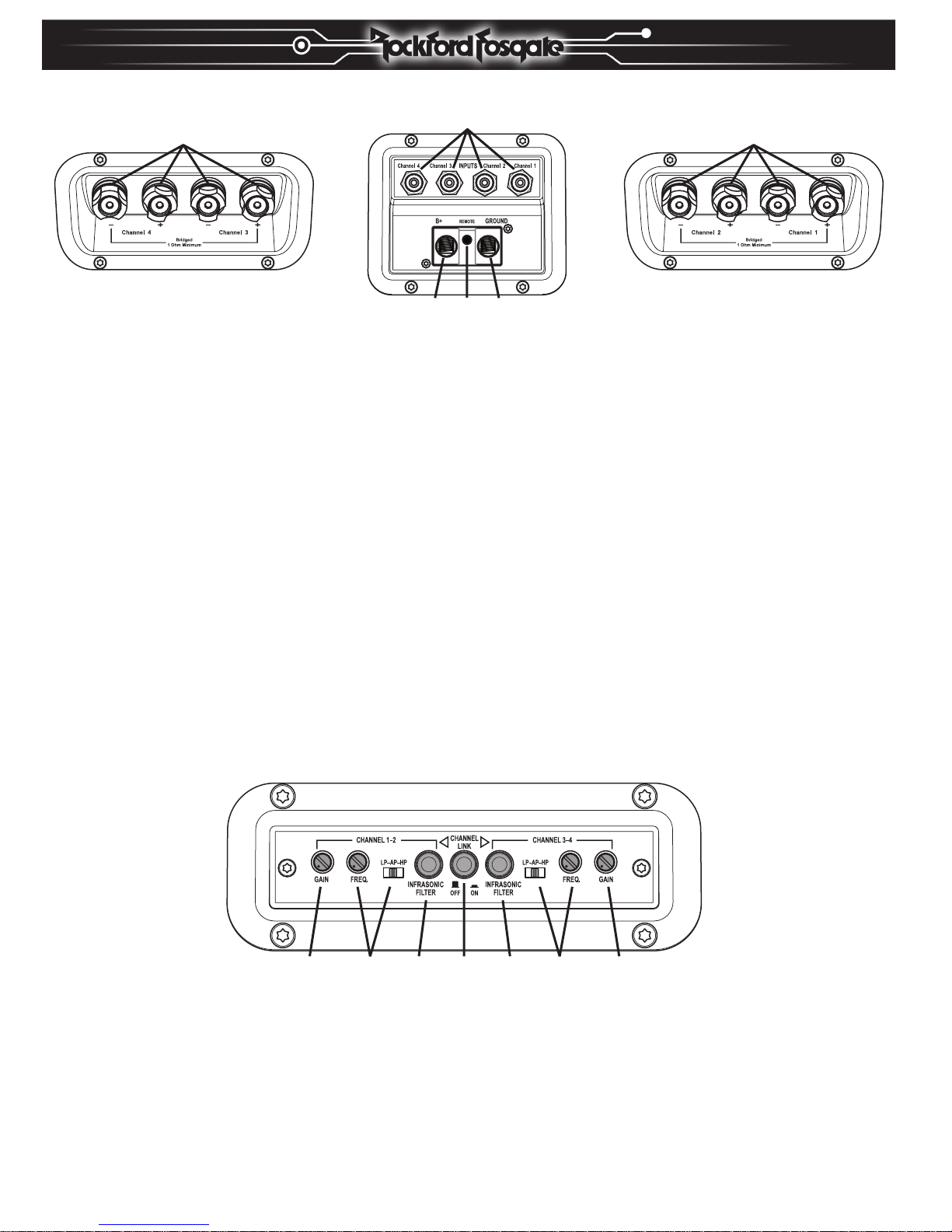
Back Panel – RCA Inputs, Power Connection and Speaker Outputs
1. Power Terminals – The power and ground connectors on the amplifier are platinum-plated and will accommodate up to
1/0 AWG wire, maximizing the input current capability of the amplifier.
2. REMOTE Terminal – This heavy duty, platinum-plated wire connector will accept wire sizes from 12 AWG to 24 AWG.
This terminal is used to remotely turn-on and turn-off the amplifier when +12V DC is applied.
3. RCA Input Jacks – The industry standard RCA jacks provide an easy connection for signal level input.They are platinum-plated
to resist the signal degradation caused by corrosion.
4. Speaker Terminals – These high current binding posts (+ and -) will accept wire sizes up to 4 AWG.
Front Panel – Controls
5. Gain Control – The input gain control is preset to match the output of most source units. It can be adjusted to match output
levels from a variety of source units. Setting displayed at item 16 on the top panel status board.
6. Variable Crossover – Is a built-in 12dB/octave Butterworth filter selectable for Low-Pass (LP),All Pass (AP), or High-Pass (HP)
operation variable from 32Hz to 300Hz. Setting displayed at item 17 on the top panel status board.
7. Infrasonic Filter Button Switch – Pressing this switch in, switches on a 24dB/octave infrasonic filter designed to prevent fre-
quencies below the audio range from being applied to the subwoofer from the amplifier. Consequently improving subwoofer performance and power handling, particularly in vented enclosures.
8. Channel Link Button Switch – Pressing this switch in, switches the inputs to a 2-channel mode, allowing connection to only
the Channel-1 and Channel-2 inputs with a full 4-channel output. Setting displayed at item 15 on the top panel status board.
NOTE: When the Channel Link Button Switch is engaged, only the Channel 1-2 controls will function and the gain and frequency
displays on the top panel status board for channels 3 and 4 will turn off.
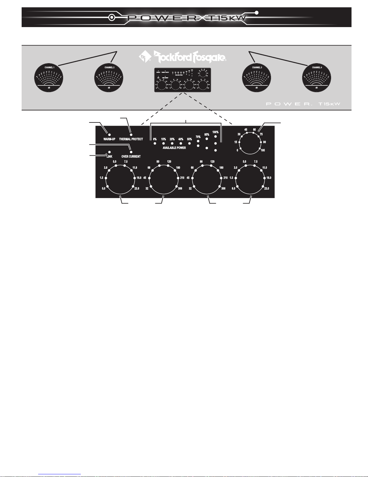
Top Panel – Status Boards
9. Output Display – These LED needle simulation displays show the real-time output of the amplifier from - 00(infinity) to +2dB.
During normal operation the indicator should not reach +2dB, as this indicates clipping.
10. Warm-Up – This LED will be on while the unit warms up when it is first turned on. Depending on the available power, the unit
may take up to a minute to warm up.
11. Thermal Protect – This LED comes on if the amplifier reaches the third stage of thermal protection.The amplifier will shut
down to cool if this occurs.
Back Panel — RCA Inputs, Power Connection and Speaker Outputs
4 4
3
121
Front Panel – Controls
5678765
5
DESIGN FEATURES
Top Panel — Status Boards
12. Available Power – These LEDs show the reserve energy of the hybrid system available for output power.
NOTE: If the available power display constantly reads below 70%, check the supply power system or reduce the amount of load
connected to the amplifier.
13. Temperature °C – These LEDs display the internal temperature of the MOSFETS.
14. Over Current – This LED comes on if there is a short in the speaker wiring, damage to speakers, or the connected load is
bellow 0.5-ohm stereo and 1-ohm bridged.The audio will also mute if this occurs.
15. Link – This LED will show if the Channel Link has been turned on. if on, only the Channel 1-2 controls will function and the
gain and frequency displays for channels 3 and 4 will turn off.
16. Gain dB – These LEDs show the gain setting on the front panel controls 0.0 to 23.0 dB.
17. Frequency Hz – These LEDs show the crossover frequency setting on the front panel controls 32Hz to 300Hz.
Special Design Features
- Patent pending Hybrid Technology power supply design
- Dual oversized toroidial transformers
- 16 High Current TO-247 Power MOSFETs in power supply section
- 80 Precision Matched TO-3P High Current MOSFETs in output section
- Power Supply switching rate 33,000 times per second
- 94,000 micro-Farads of power supply filter capacitance
- One hundred and eighty 400 Farad ultracapacitors in power supply's Hybrid system
- Active and Passive capacitor balancing circuitry
- Reserve Energy of over 200,000 Joules
- Forced air thermostatically controlled fan cooling system
- 375 Amps maximum current draw
- Large Extruded Aluminum Internal Heatsinks for cooling of MOSFET devices
- Separate PCBs for; Preamplifier,Amplifiers, and Power Supply for low noise operation
- 1% tolerance resistors and high quality film capacitors in audio signal path
9
10
14
15
11
16 17
12
9
13
1617
 Loading...