

Rockford Fosgate P1-SVC, Punch P1S48, Punch P1S88, Punch P1S410, Punch P1S810 Installation & Operation Manual
...Page 1
LJ
N
P1-SVC
-
SINGLE
VOICE
COIL
SUBWOOFERS
4-0hm
8-0hm
8"
P1S48
P1S88
10
1
'
P1S410
P1S810
12"
P1S412
P1S812
15"
P1S415
P1S815
Installation
&
Operation
Serial
Number:
_
DateofPurchase:
----
Page 2
SAFETY
CARTON CONTENTS
~
CAUTION:
Before installation, disconnect
the
battery
negative (-) terminaltoprevent
damage
to
the
unit, fire
and/or
possible injury.
( I) Punch P I Series
Subwoofer
(I) Painted PVC
decorative
trim
ring
(8)
Socket
head
wood
screws
(8)
"Speed
Clips"
screw
mounting
clips
(I)
Socket
head
driver
bit
RECOMMENDED
ENCLOSURES
This manual outlines
two
specific
typesofenclosures
that
provide
distinctly different
performance.
This
sectionisto
help you decide
which
typeisbest
for
your
application.
SEALED
ENCLOSURES
Sealed
enclosures
are
the
simplesttobuild.
The
most
important
part
of
building a sealed
enclosureisto
make
sure
that
the
enclosureisairtight.
Using glue and
some
typeofsealantonail
seams
will
ensure
solid
construction
and
prevent
air leaks.
The
box
volume will directly impact
the
performanceofthe
speaker. Larger
enclosures
will provide flatter
response
and
deeper
bass
where
smaller
boxes
will provide a bump
in
the
response
curve
and generally higher
output
for
greater
SPL.
BUILDING
AN
ENCLOSURE
To
work
properly,
the
wallsofthe
enclosure
mustberigid and
not
flex
when
subjectedtothe
high
pressures
generatedbythe
speaker's
operation.
For
optimum
performance,werecommend
using 3/4" MDF
(Medium Density Fiberboard) and internal bracing.
The
enclosure
should
be
glued
together
and
secured
with nailsorscrews.
CALCULATING
VOLUME
Calculating volumeismerely a
matterofmeasuring
the
dimensions
in
inches and using
the
formula: H x W x D divided by 1728 (cubic feet).
See
block
below.
120.0...------t---1----+--I---+--+---+---+-+------+---1---I---I--+-+--I--+--I
Advantages ofsealed enclosures:
Small
enclosures
Linear (Flat)
response
No
port
noise
High
power
handlingatall
frequencies
Excellent
for
sound
quality
Extended low frequency
output
when
comparedtovented
enclosures
VENTED
ENCLOSURES
Vented
enclosures
vary only from
the
sealed
enclosureinthatavent
or
portisaddedto"tune"
the
enclosure.
The
enclosures
recommended
are
designed
for
great
overall
performance.
Larger boxes
tendtobe easy
to
tunetolower
frequencies while medium and small boxes
are
easier
to
tunetohigher frequencies.
The
vented
designisless linear
in
response
than
the
sealed
box
but
with noticeably
more
output
at
the
tuning frequency.
BoxVolume
Height"xWidth"xDepth"
Dividedby(cubic
feet)
I
728
If
two
facing sides
areofuneven length, add
them
together
and divide by
twototake
the
average. Using this
number
will
give you
the
volume
without
the
necessityofcalculating
the
boxinsections and adding
the
sections
together.
The
thicknessofthe
baffle material
reduces
the
internal
volume
so
this
mustbesubtracted
from
the
outside
dimensions
to
determine
the
internal volume.
The
speaker
itself also
reduces
the
internal volume.
The
amountofair displaced by each modelislisted
on
the
specification
sheet
and should alsobesubtracted
from
the
gross
volume calculation.
Advantages of
vented
enclosures:
Higher average
output
than
sealed
Tuning frequency can
be
easily adjusted by changing
port
length
Deep
bass
response
with
lower
power
requirements
Great
for
high
output
with
limited
power
110.0
'I------t----f---+-+---J---+-+-1--+------+----+---I---+--+--+---+--l-I
,
100.0i-----+----I1-'--t--;;;;;<JdIIlfII..----III/I··...".-+'--+If/II'--+--f-+-------+------+--+-+--+-+-J-+--I
1-------------_._----_.-----1----------,-,'-+--------:,,::::-+-
---+----+--+--+---1--------------------·-·--·-
1--···
·----------+----------1-------1-------1------1-----1----~---I
90.0
+-----t--:L,.,,'--.::.l//I>llI!P
...
.dIIJ4-III/I--t--+--+-+-+---+-1-------+----+--+-+--+-+--~
...
1--------------_--",~-d!IUP'.-7"1'---1-----------
--+---------.-+------\-------1-----1------\---+--1------·----------------------+-------------1-----------1--------1------1------1-----1------1---1
80.0
",,16fIJI'
I
_1IIfIIIII"
I ---+·--·-----·--------1-----------1-----+-----+---+----+--·--j----f------------------------+--------·------+---------+-------1-------1-----1----
AII1!P"
I
_____
I
70.0
~~F~-----------------------I--
,-----------I---------+------+-------I-----+---j-+--+---.----.-------------------j--------------+---------+----+---
---
-------------1
I
1000.0200.060.0 80.0 100.0
Frequency, Hz
60.0
...---_....l-
__
I.----..._..l.--'--...I.-
.........
--w-
---Io
__
-"--_..L..---l-....L.--I-....l--'--I
10.0 20.0 40.0
.",111/.1<.
Sealed Box _ Vented Box
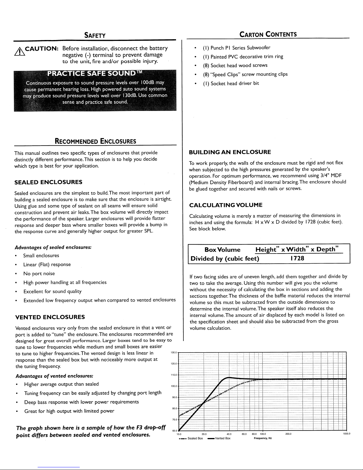
The graph shown here
is
a sample
of
how
theF3drop-off
point
differs
between
sealed
and
vented
enclosures.
Page 3

SEALED
ENCLOSURES
NOTE:
Vbisthe
gross volume, whichisthe
TOTAL internal volume, before any
speaker
and/or
port
displacement.
All
external dimensions
were
basedonthe
useof3/4" (1.90cm) materials.
NOTE:
When
using enclosures
other
than recommended,
call
Technical
Support
for
correct
application.
Optimum
Sealed
Enclosure
Recommendation
Recommended
Sealed
EnclosureVolume Range
SEALDED
ENCLOSURES
8
11
1011
12
11
15
11
Pl
8481
Pl
S88
P1S4101Pl881
0
P1S412
1Pl8812
P1S415
1Pl8815
Vb-
Internal
Area
cu.
ft.
0.23
0.59
1.02
1.58
(Liter)
(6.51)
(16.42)
(28.88)
(44.74)
F3-
-3dB
Point
(Hz)
62.1
50.9
43.5
39.0
Qtc-
Enclosure
Damping
0.877
0.875
1.097
1.266
H-
Height-inch
10.0
12.0
14.0 18.0
(cm)
(25.40)
(30.48)
(35.56)
(45.72)
W-
Width-inch
12.0
14.0 18.0
21.0
(cm)
(30.48)
(35.56) (45.72)
(53.34)
D-
Depth-inch
6.0
9.25
10.0
10.0
(cm)
(15.24)
(23.50)
(25.40)
(25.40)
VENTED
ENCLOSURES
SEALDED
ENCLOSURES
8
11
Pl
848/PlS88
Vb-
Volume
Range
cu.
ft.
0.20to0.30
(Liter)
(5.66to8.50)
1011
12
11
15
11
Pl
S4101Pl8810P1S412
1Pl8812
P1S4151P1S815
0.50to0.85 0.70to1.80
1.30to3.50
(14.16to24.07)
(19.82to50.97)
(36.81to99.10)
Specifications
subject
to
change
without
notice
NOTE:
Vbisthe
gross volume, whichisthe
TOTAL internal volume, before any
speaker
and/or
port
displacement.
All
external dimensions
were
basedonthe
useof3/4" (1.90cm) materials.
NOTE:
When
using enclosures
other
than recommended,
call
Technical
Support
for
correct
application.
Optimum
Vented
(Ported)
Enclosure Sizes
VENTED
ENCLOSURES
8
11
1011
12
11
15
11
P1
8481
Pl
S88
Pl
S4101Pl881
0
P1S412
1Pl8812
P1S415
1Pl8815
Vb-
Internal
Area
cu.
ft.
0.65
1.40
1.79
2.66
(Liter)
(18.41) (39.64)
(50.69) (75.32)
Fb-
Tuning
Frequency
(Hz)
42.7
37.3
36.3
34.4
F3-
-3dB
Point
(Hz)
36.8 32.6
34.4 33.9
H-
Height-inch
12.0 12.0 14.0
18.0
(cm)
(30.48) (30.48)
(35.56)
(45.72)
W-
Width-inch
18.0
20.0
25.0
28.0
(cm)
(45.72)
(50.80) (63.50)
(71.12)
D-
Depth-inch
8.0
14.0
12.0
12.0
(cm)
(20.32) (35.56) (30.48) (30.48)
P-
Port
Diameter
and
Length-inch
(1)
2x 6
(1)
3x 8
(1)
3x 6
(1)
4x8
(cm)
(1)
(5.08x15.24)
(1)
(7.62x20.32)
(1)
(7.62x15.24)
(1)
(10.16x20.32)
Numberofports
notedin()
Specifications
subject
to
change
without
notice
NOTE:
The
port
shown can be placed on any face of
the
enclosureaslongasthe
port
ends are
not
obstructed.
3
Page 4

PHYSICAL DIMENSIONS
PUNCH
P1-SVC
8
11
1011
12
11
15
11
Pl
S481
Pl
S88
Pl
S4101P1S810
P1S412
1
P1S812
P1S4151P1S815
A -
Trim
Ring
Diameter-inch
8.75
10.875
12.75
15.50
(cm)
(22.23)
(27.62)
(32.39)
(39.37)
B -
Trim
Ring
Heigth-inch
0.50
0.625
0.625
0.75
(cm)
(
1.27)
(1.59)
(1.59)
(1.90)
c-
Mounting Diameter-inch
7.125 9.25
11.125
13.875
(cm)
(18.10)
(23.50)
(28.26) (35.24)
D-
Mounting Depth-inch
4.125
5.125
5.875 6.875
(cm)
(10.48)
(
13.02)
(
14.92)
(
16.83)
E-
Overall Diameter-inch
8.50
10.625
12.50
15.25
(cm)
(21.59)
(27.00)
(31.75)
(38.42)
F -
Screw Hole Diameter-inch 8.00
10.25
12.125
14.875
(cm)
(20.32)
(26.04) (30.80)
(37.78)
G - Speaker Displacement -
cu.
ft.
0.024
0.043 0.048
0.060
(Liter) (0.69)
(
1.22)
(
1.36)
(1.70)
Specifications
subjecttochange
without
notice
I~..---[Q]f-------~"I
4
Page 5

SPECIFICATIONS
PUNCH
Pl-SVG
8
11
1011
12
11
15
11
P1
5481
P1
S88
P1S4101P1
S81
0
P1S4121P1S812
P1S4151P1S815
Nominal Impedance (ohms)
4/8
4/8
4/8
4/8
Frequency Response
(Hz)
40-250
30-250
26-250
24-250
Voice
Coil
Diameter -
inch
1.50
(4-Layer)
1.50
(6-Layer)
1.50
(6-Layer)
1.50
(6-Layer)
(cm)
(3.81)
(3.81)
(3.81) (3.81)
Displacement -
cu.
ft.
0.024 0.043
0.048 0.060
(Liter)
(0.69)
(
1.22)
(
1.36)
(
1.70)
Fs
- Free Air Resonance
(Hz)
40
30
26
24
Qts 0.52/0.54
0.52/0.55
0.53/0.57
0.62/0.66
Vas-cu.
ft.
0.48
1.57
3.88
6.07
(Liter)
(13.5) (44.4)
(110.0) (
172.0)
Xmax -
inch
0.275
0.295 0.295
0.315
(cm)
(0.70)
(0.75)
(0.75) (0.80)
SPL
(dB
@ Iw/l
m)
84
85
86
87
Power Handling-Watts
(RMS)
150
150
150
200
(Peak)
300
300
300
400
Specifications subjecttochange
without
notice
..
+
20-
WIRING
CONFIGURATIONS
By
varying
the
wiring configurationofyour
speakers you can
create
an
impedance load
to
match
your
system.Altering
the
wiring configurations
gives a range
of
options for impedance loads. Series, Parallel,
or
Series-Parallel wiring configurations
are
different techniques for wiring
speakers
that
provide different loads. Series configurationisa string
method
where
speakers
are
wired endtoend. Parallel configuration
uses
twoormore
speakers wired across
common
terminals.
Series-Parallel configuration combines both techniques.
Choose
the
wiring diagram
that
correspondstothe
numberofwoofers and
the
impedanceofyour
amplifier.
Parallel Wiring
(2)
4
ohm
SVC Speaker =2 ohm
Load
SUB'NOOFER
CROSSOVERS
There
are
two
operational typesofcrossovers, passive and active.
Passive crossovers (coils
or
inductors)
are
placed on
the
speaker leads
between
the
amplifier and speaker.An active crossoverisan electronic
filter
that
separates
the
audio signal fedtodifferent amplifiers. For
optimum subwoofer performance,
we
recommend using an active
80-100Hz low-pass
crossoverat12dB/octave.
5
Series/Parallel Wiring
®
40
(4) 4
ohm
SVC Speaker =4 ohm
Load
Page 6

FEATURES
Protective
PVC
textured
magnet
cover.
High density
compressed
half-roll sealed
poly-foam
surround
Tear and fatigue
resistant
poly-cotton
spider.
Vented
spider
cavity.
/
Decorative
ABS
Trim Ring.
High Modulus Polypropylene Cone/Acrylic dustcap assembly.
Custom
insulated IO-AWG nickel plated push terminals.
Sturdy
16
gauge
compound
bend
frame.
Optimized
motor
magnetics
with
extended
pole piece and
bumped
backplate.
• High
modulus
closed conical polypropylene
cone
and
ABS/Acrylic
dustcap
assembly
geometry.
•
Tear
& fatigue
resistant
poly-cotton spider.
• High
density
compressed
half-roll
sealed
poly-foam
surround.
• High
temp
voice coil
with
spun-laced
Nomex
™ insulating
re-inforcment
collar.
•
Optimized
motor
magnetics
with
extended
pole
and
bumped
backplate.
•
Fatigue
resistant
and
reduced
strain
"stitched
on"
flexible lead
wire
design.
• Multi-point
high-temp/high-strength
neck
joint
bonding
technique.
•
Sturdy
16
guage
compound
bend
frame
geometry.
• Semi-flexible PVC
removable
protective
motor
cover.
•
Custom
insulated/isolated
compression
input
terminal
assembly.
•
Proprietary
spider
venting/cooling
technique.
8
Page 7

LIMITED
WARRANTY
STATEMENT
Rockford Corporation offers a limited warranty on Rockford Fosgate products on
the
following terms:
LengthofWarranty
Speakers
- IYear.
Any
Factory
Refurbished
Product
- 90 days
(receipt
required)
WhatisCovered
This warranty applies onlytoRockford Fosgate products soldtoconsumersbyAuthorized Rockford Fosgate
Dealers
in
the
United States ofAmericaorits possessions. Product purchasedbyconsumers from
an
Authorized Rockford Fosgate Dealerinanother
country are covered onlybythat
country's Distributor and
notbyRockford Corporation.
WhoisCovered
This warranty covers only
the
original purchaserofRockford product purchased from an Authorized
Rockford Fosgate Dealer
in
the
United States.Inordertoreceive service,
the
purchaser must provide
Rockford with a copy of
the
receipt stating
the
customer name, dealer name, product purchased and date of
purchase. Products found
to
be defective during
the
warranty period
will
be repairedorreplaced
(with a product deemed
to
be equivalent)atRockford's discretion.
What
is
Not
Covered
I.
Damage causedbyaccident, abuse, improper operations, water, theft, shipping
2.Any
costorexpense relatedtothe
removalorreinstallation of product
3.
Service performedbyanyone
other
than Rockfordoran Authorized Rockford Fosgate Service
Center
4.Any product which has had
the
serial number defaced, altered,orremoved
5.
Subsequent damagetoother
components
6.Any product purchased outside
the
U.S.
7.Any product
not
purchased fromanAuthorized Rockford Fosgate Dealer
LimitonImplied Warranties
Any
implied warranties
including
warranties of fitness for use and merchantability are limitedindurationtothe
period of the express warranty set forth above. Some states do
not
allow limitations on the length ofanimplied
warranty, so this limitation
may
not
apply.Nopersonisauthorizedtoassume for Rockford Fosgate
any
other
liabilityinconnection with the sale of the product.
HowtoObtain Service
Contact
the
Authorized Rockford Fosgate Dealer you purchased this product from.Ifyou need further
assistance,
call
1-800-669-9899 for Rockford
Customer
Service.You must obtain an
RA#
(Return
Authorization
number)
to
return any producttoRockford Fosgate.You are responsible for shipment
of product
to
Rockford.
EUWarranty
This product meets
the
currentEUwarranty requirements, see yourAuthorized dealer for details.
Check
our
website
for
additional
information
and
updatesonthese
products.
www.RockfordFosgate.com
©2006 Rockford
Corporation.
All
rights reserved.
Rockford Fosgate,
the
Rockford Fosgate logo, and
the
PUNCH
logo
are
either
registered
trademarksortrademarksofRockford
Corporation.
12/068.M.
1230-533
13-01
Printed in China
 Loading...