

Rockford Fosgate P132, P142, P152, P15652, P1653 Installation & Operation Manual
...
u
N
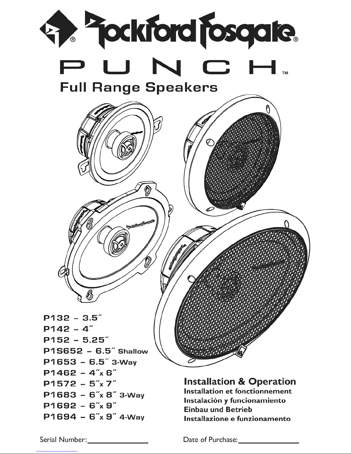
Full
Range
Speakers
P132
P142
P152
P15652
P1653
P1462
P1572
P16B3
P1692
P1694
Serial Number: _ Date of Purchase: _
-
-
-
3.5"
4··
5.25··
-
-
6.5··
-
4··x
-
5··x
-
6··x
-
6··x
-
6··x
6.5··
3-Way
6··
7··
B··
9··
9··
Shallow
3-Way
4-Way
Installation &
Installation
Instalaci6n y funcionamiento
Einbau
Installazioneefunzionamento
und
et
Betrieb
Operation
fonctionnement
SAFETY
Before installation, disconnect the battery
negative (-) terminal
to
the
unit, fire and/or possible injury.
PRACTICE
Continuous exposure[0sound pressure levels over 1000B
cause penTIanent hearing
may
produce sound pressure levels
sense and practice safe sound.
CARTON CONTENTS
(I)
P'loir
Punch
~
lVll
<I)
P'loir
of
grilIesItrim
<I)
PloiroflocbfKu pbtes
(2)
P10ir
of.1cbpw' plates (PI52,
Mounting HJ.rdw.lre
rirlp
(P14t
SAFE
10$$.
High
R.an&e
$peaktn
(PI S1, PIS651, PI6S),
Pl0462.
PIsnonly)
PI
5652,
PI6S)
to
SOUND'"
powered
well
over
PI692
only)
prevent damage
auto
sound systems
13OdB.
and
may
Use common
PI6'J1
only)
..•..
//~~
U'.
I...
'.
......
............
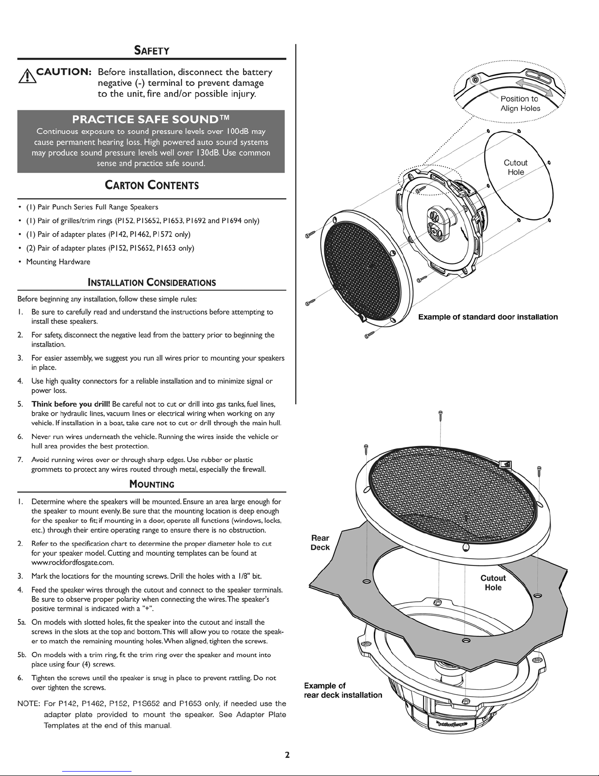
Position
Align
_--------~--~
to
Holes
~~
'
>
•
Befot'e
beginn;ng
I.
Be
~chese~
2. For
insQbtion.
3.
For
in
pbce.
<t.
Use
any
~
to
amuly
~kty,
disconnect
easier
assembly.
high
quaiit)' connectors for
..........
5.
Think
before
bnke
or
hydr.llulic
vehicle. If installation
6.
Never
rurl
hull area provides the
7. Avoid rurlrlirlg
grommeutoprotect
I.
Determine
the
for
etC.)
2.
Reier
for
www.rocldordlospte.cOtn.
J.
Mat1l.
~.
Feed
Be
positive
Sa..
On mode/$
screws
ertomatch
so.
On mode/$ with a
pbce
6.
Tighten the
O¥ef"
NOTE:
wi~s
wi~s
wne~
speakertomount
the
speake!"
through their
to
the specification
your
speake<'
the
Ioations
the
spe.akef'......-es
SUf'e
to
obser¥e
renninal
witto
in
the
slots
the
uWl&
b."
screws
ti&"ten
the
F()(
P142, P1462,
adapter plate
Templates
INSTALLATION
in$aIbtion,
Itid
and
the
nepthoe lead from
_
wuest)'OU
you drill!Beareful
lines. Y1(uum linesorele<tric.al
in
a
!loa[,
underneath
best
protection.
overorthrough sharp edges. Use
any wires
CONSIDERATIONS
foIow
these
understand
run
lo
relW;lle installation
r.ot
take
a~
the
vehicle. RUMing
routed
through metal, especially
simple rules:
~
to
not
MOUNTING
the
speakers
evenly.Besure
to
fie;
ifmounting
entire
model
lor
proper pobrity
is
indicated
slotted
at
the
~
trim
(-4)
iCf'eWS.
until the speaker is
iCf'eWS.
provided
at
the end01this
willbemounted. Ensure an area large enough for
that
in
opet1ting rangetoerlsure
chantodetermine
Cuttitlt:
the
t!v"ougtl
holes.
top
q fit the
a door,
and mounting
ITIOI.Wltins:
mourltin&
screws. Drill
the
eutDut
when
with a"+".
fit the
spe.akef'
and bottom.
holes.When
trim
rin&
snug
Pl52,
P1S652
to
mount
manual.
die
instruetion$
the
~
cutordrill
to
cutordrill through
the mourltirlg location
operate
the
templates
and
connect
conn«tirlg the wires.The speaker's
into
This
will.,....,
0'0'er
in pbce
and
P1653 only, if needed use the
the speaker.
~
loUempOng
b3.tt~
prioo'
to
begming
prior
to
mounting your
and
to
minimize
into
gas
wiri~
the
wi~s
all
there
proper
the
holes with a IIfr'
the
o1.Iigned.
the
speaker
to
tanks,
wben
worki~
inside
the
rubberorplastic
the
functions (wirldows,locks.
C\ItOtIt
~
is
is no
obstruction.
diameter
an
be
found
to
the
speaker tenl'Iinak.
and
you
to
rotate
Dgtlten
the
and
ratding..
see
mall
mount into
Adapter Plate
signal
fuel
the
firewall.
deep
hole
~
speaken
on
m<lirl
vehicle
enough
to
at
bit..
the
the
Do
to
the
or
ijnes,
any
hull.
CUt
speak.
not
EJr:ampleofstandard
or
Rear
door
installaUon
De"
Cutout
Ho~
Exam~of
rear
de<:k installaUon
2

SPECIFICATIONS
P1 Full Range
Nominal Diameter - inch (mm) 3.5” (89) 4.0” (102) 5.25” (133) 6.5” (165) 6.5” (165) 4” x 6” (102 x 152)
Description 2-Way 2-Way 2-Way 2-Way 3-Way 2-Way
Nominal Impedance (ohms) 4Ω 4Ω 4Ω 4Ω 4Ω 4Ω
Frequency Response (Hz) 120-22kHz 100-22kHz 70-22kHz 65-22kHz 60-24kHz 90-22kHz
Voice Coil Diameter - inch (mm) 0.75 (20.0) 1.0 (25.4) 1.0 (25.4) 1.0 (25.4) 1.0 (25.4) 1.0 (25.4)
Fs - Free Air Resonance (Hz) 120 Hz 100 Hz 70 Hz 65 Hz 60 Hz 90 Hz
Qts 0.60 0.80 0.68 0.68 0.68 0.80
Vas - cu. ft. (Liter) 0.03 (0.9) 0.09 (2.5) 0.19 (5.4) 0.60 (16.8) 0.60 (16.8) 0.08 (2.2)
Xmax - inch (mm) 0.04 (1.0) 0.06 (1.5) 0.08 (2.0) 0.14 (3.5) 0.14 (3.5) 0.08 (2.0)
SPL (dB @ 1w/1m) 85 dB 86.5 dB 87 dB 88 dB 89 dB 87.5 dB
Power Handling-Watts (RMS / Peak) 20 W / 40 W 30 W / 60 W 40 W / 80 W 55 W / 110 W 60 W / 120 W 35 W / 70 W
Mounting Diameter-inch (mm) 3.21 (81.59) 4.04 (102.55) 4.81 (122.21) 5.05 (128.19) 5.57 (141.35) 3.63 x 5.80 (92.28 x 147.40)
Mounting Depth-inch (mm) 1.38 (35.00) 1.69 (43.00) 1.87 (47.50) 1.89 (48.00) 2.17 (55.00) 1.81 (46.00)
Includes Grille/Trim Ring NO NO YES YES YES NO
Trim Ring Diameter-inch (mm) – – 6.22 (158.00) 6.89 (175.00) 6.97 (177.00) –
Trim Ring Height-inch (mm) – – 0.88 (22.34) 0.93 (23.68) 0.83 (21.00) –
Includes Adaptor Plate NO 4”x6”/6”x8” 5”x7”/6”x9” 5”x7”/6”x9” 5”x7”/6”x9” 6”x8”
P132 P142 P152 P1S652 P1653 P1462
Specifications subject to change without notice.See figures on following pages.
SPECIFICATIONS
P1 Full Range
Nominal Diameter - inch (mm) 5” x 7” (127 x 178) 6” x 8” (152 x 203) 6” x 9” (152 x 229) 6” x 9” (152 x 229)
Description 2-Way 3-Way 2-Way 4-Way
Nominal Impedance (ohms) 4Ω 4Ω 4Ω 4Ω
Frequency Response (Hz) 75-22kHz 65-24kHz 60-22kHz 60-24kHz
Voice Coil Diameter - inch 1.0 (25.4) 1.0 (25.4) 1.0 (25.4) 1.0 (25.4)
Fs - Free Air Resonance (Hz) 75 Hz 65 Hz 60 Hz 60 Hz
Qts 0.68 1.00 0.72 0.72
Vas - cu. ft. (Liter) 0.19 (5.4) 0.48 (13.6) 0.78 (22.0) 0.78 (22.0)
Xmax - inch (mm) 0.08 (2.0) 0.14 (3.5) 0.18 (4.5) 0.18 (4.5)
SPL (dB @ 1w/1m) 89 dB 90 dB 91 dB 91 dB
Power Handling-Watts (RMS / Peak) 60 W / 120 W 65 W / 130 W 75 W / 150 W 75 W / 150 W
Mounting Diameter-inch (mm) 4.58 x 6.71 (116.25 x 170.42) 4.88 x 6.92 (124.00 x 175.82) 5.62 x 8.28 (142.70 x 210.42) 5.62 x 8.28 (142.70 x 210.42)
Mounting Depth-inch (mm) 2.20 (56.00) 2.28 (58.00) 3.07 (78.00) 3.07 (78.00)
Includes Grille/ Trim Ring NO NO YES YES
Trim Ring Diameter-inch (mm) – – 7.56 x 10.24 (192.00 x 260.00) 7.56 x 10.24 (192.00 x 260.00)
Trim Ring Height-inch (mm) – – 0.82 (20.86) 0.82 (20.86)
Includes Adaptor Plate 6”x8” NO NO NO
P1572 P1683 P1692 P1694
See figures on following pages.
Specifications subject to change without notice.
3
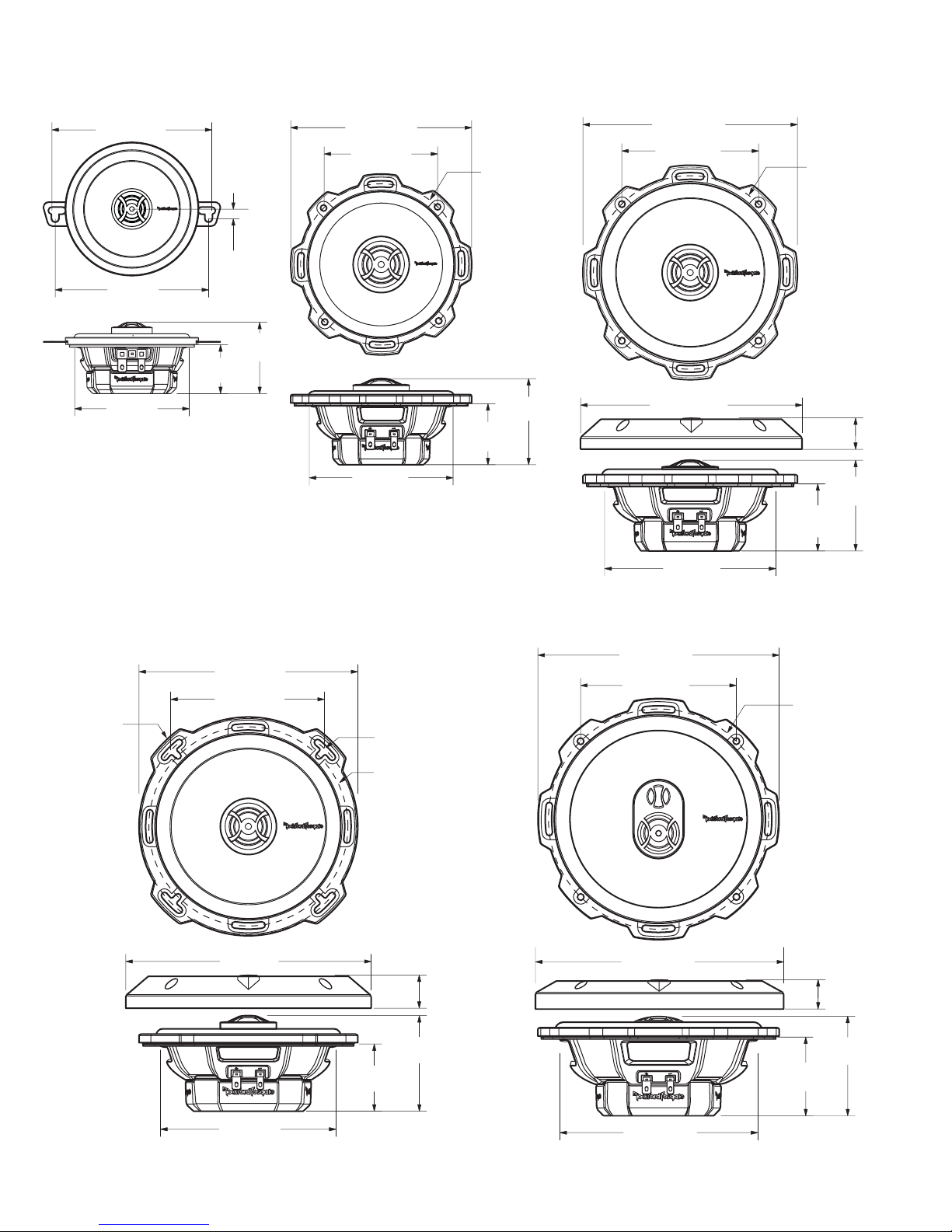
SPECIFICATIONS
P142P132
4.50"
(114.07mm)
0.26"
(6.70mm)
4.31"
(109.40mm)
2.00"
(50.74mm)
1.36"
(34.50mm)
3.21"
(81.59mm)
Cutting and mounting templates available at:
www.rockfordfosgate.com/rftech.
(129.00mm)
(80.98mm)
(102.55mm)
5.08"
3.19"
4.04"
4.53"
(115.00mm)
Diameter
(61.37mm)
1.71"
(43.50mm)
2.42"
P152
6.02"
(153.00mm)
3.84"
(97.58mm)
6.22"
(158.00mm)
4.81"
(122.21mm)
(138.00mm)
Diameter
(22.34mm)
1.87"
(47.50mm)
5.43"
0.88"
2.55"
(64.67mm)
P1S652 P1653
6.69"
(170.00mm)
Diameter
6.14"
(156.00mm)
4.31"
(109.60mm)
6.89"
(175.00mm)
6.10"
(155.00mm)
Diameter
5.59"
(142.00mm)
Diameter
0.93"
(23.68mm)
2.68"
(68.17mm)
1.89"
(48.00mm)
6.77"
(172.00mm)
4.37"
(111.02mm)
6.97"
(177.00mm)
(157.00mm)
Diameter
0.83"
(21.00mm)
2.17"
(55.00mm)
6.18"
2.80"
(71.10mm)
5.05"
(128.19mm)
Specifications subject to change without notice.
5.57"
(141.35mm)
4
 Loading...