

Page 1

®®
INSTALLATION
& O PERATION
HIGH
PERFORMANCE
PARAMETRIC
EQUALIZER
Page 2

Dear Customer,
Congratulations on your purchase of the world's finest brand of car audio signal
processors. At Rockford Fosgate we are committed to musical reproduction at its best,
and we are pleased you chose our product. Through years of engineering expertise, hand
craftsmanship and critical testing procedures, we have created a wide range of products
that reproduce music with all the clarity and richness you deserve.
For maximum performance we recommend you have your new Rockford Fosgate
product installed by an Authorized Rockford Fosgate Dealer, as we provide specialized
training through Rockford Technical Training Institute (RTTI). Please read your
warranty and retain your receipt and original carton for possible future use.
To add the finishing touch to your new Rockford Fosgate image order your Rockford
accessories, which include everything from T-shirts and jackets to hats and sunglasses.
To get a free brochure on Rockford Fosgate products and Rockford accessories, in the
U.S. call 602-967-3565 or FAX 602-967-8132. For all other countries, call +001-602-
967-3565 or FAX +001-602-967-8132.
The serial number can be found on the outside of the box. Please record it in
the space provided below as your permanent record. This will serve as
verification of your factory warranty and may become useful in recovering your
equipment if it is ever stolen.
Serial Number: ____________________
Model Number:____________________
If, after reading your manual, you still have questions regarding this product,
we recommend that you see your Rockford Fosgate dealer. If you need further
assistance, you can call us direct at 1-800-795-2385. Be sure to have your serial
number, model number and date of purchase available when you call.
PRACTICE SAFE SOUND™
CONTINUOUS EXPOSURE TO SOUND PRESSURE LEVELS OVER
100dB MAY CAUSE PERMANENT HEARING LOSS. HIGH POWERED AUTO SOUND SYSTEMS MAY PRODUCE SOUND PRESSURE LEVELS WELL OVER 130dB. USE COMMON SENSE AND
PRACTICE SAFE SOUND.
Page 3

TABLE OF CONTENTS
Introduction ............................................................................................1
Accessory Pack .......................................................................................1
Technical Design Features ......................................................................2
Design Features.......................................................................................3
Installation Considerations ......................................................................5
Mounting Location..................................................................................6
Wiring the System ...................................................................................6
OEQ2 Installation....................................................................................8
OEQ2 Operation ...................................................................................13
System Diagrams...................................................................................16
Rockford Fosgate Accessories................................................................20
Troubleshooting ....................................................................................21
Specifications........................................................................................24
Warranty Information............................................................................25
International Information.......................................................................26
Sections marked
TROUBLESHOOTING
include recommendations
for curing
installation problems
Sections marked
INSTALLATION
include “slam dunk”
wiring connections
I
N
S
T
A
L
L
A
T
I
O
N
® ®
TROUBLE-
S
H
O
O
T
I
N
G
Sections marked
ADVANCED OPERATION
include in-depth
technical information
a
d
v
a
n
c
e
d
O
p
e
r
a
t
i
o
n
Welcome to Rockford Fosgate! This manual is designed to provide
information for the owner, salesperson and installer. For those of you who
want quick information on how to install this product, please turn to the
Installation Section of this manual or refer to the icons listed below. Other
information can be located by using the Table of Contents. We, at
Rockford Fosgate, have worked very hard to make sure all the information
in this manual is current. But, as we are constantly finding new ways to
improve our product, this information is subject to change without notice.
GETTING STARTED
Page 4

– 1 –
INTRODUCTION
The OEQ2 is an octave equalizer used to help compensate for
acoustical inaccuracies common in the automobile environment.
The OEQ2 is a stereo equalizer with ten bands of frequency adjustment spaced at octave intervals. Each band can accommodate up to
12dB of boost or cut to overcome dips and peaks in the response
curve. Frequency Warp controls shift center frequencies half an
octave up and half an octave down for precise adjustment. Input and
output gains are utilized for proper gain settings while a pair of LED
monitors track input levels. The high output voltage available from
the OEQ2 allows it to also be used as a line driver, and its low output
impedance supports the connection of several amplifiers without
signal degradation. The OEQ2 is a versatile, high performance
equalizer with convenient features that will fine tune any system and
help solve response problems.
ACCESSORY PACK
Installation and Operation Manual
(4) Mounting Screws
(1) Power Connector
Page 5

TECHNICAL DESIGN FEATURES
◆ High-Q Filters
Hi-Q filters are utilized for adjusting narrow frequency bands in an
equalizer. Filter “Q” or Quality Factor is a measure of the “narrowness” of the filter response. Using Low-Q (wide) filters in an equalizer
allows adjustments made on one control to strongly effect neighboring frequencies during boost or cut. Hi-Q filters avoid problems like
adjacent band overlap which minimize the time needed to remove
frequency response errors.
THE RESULT: Avoids adjacent band overlap through precise filtering.
◆ Frequency Warp
The Frequency Warp controls shift the center frequency of each band
higher or lower in frequency (up to 1/2 octave). This enables the
equalizer to pinpoint “dips” and “peaks” in the response curve. The
frequency warp is useful when using an RTA (Real Time Analyzer) to
find and correct problems located between the equalizer's center
frequencies.
THE RESULT: Easier to equalize response errors by pinpointing
problem frequencies.
◆ Balanced Line Inputs
Using the BLT (Balanced Line Transmitter) provides the last word in
achievable rejection of noise induced in the cable between the
source and the signal processor. The differential input circuitry used
in the balanced input system rejects whatever signals are common to
both of the shielded, twisted pair conductors. Balanced line is
universally used in concert installations where the stage and mixing
consoles are hundreds of feet apart. Long signal cables and electrically-noisy environments make signal integrity and noise rejection
an extremely difficult challenge.
THE RESULT: Quiet transmission of audio from source to signal
processor.
– 2 –
Page 6
DESIGN FEATURES
– 3 –
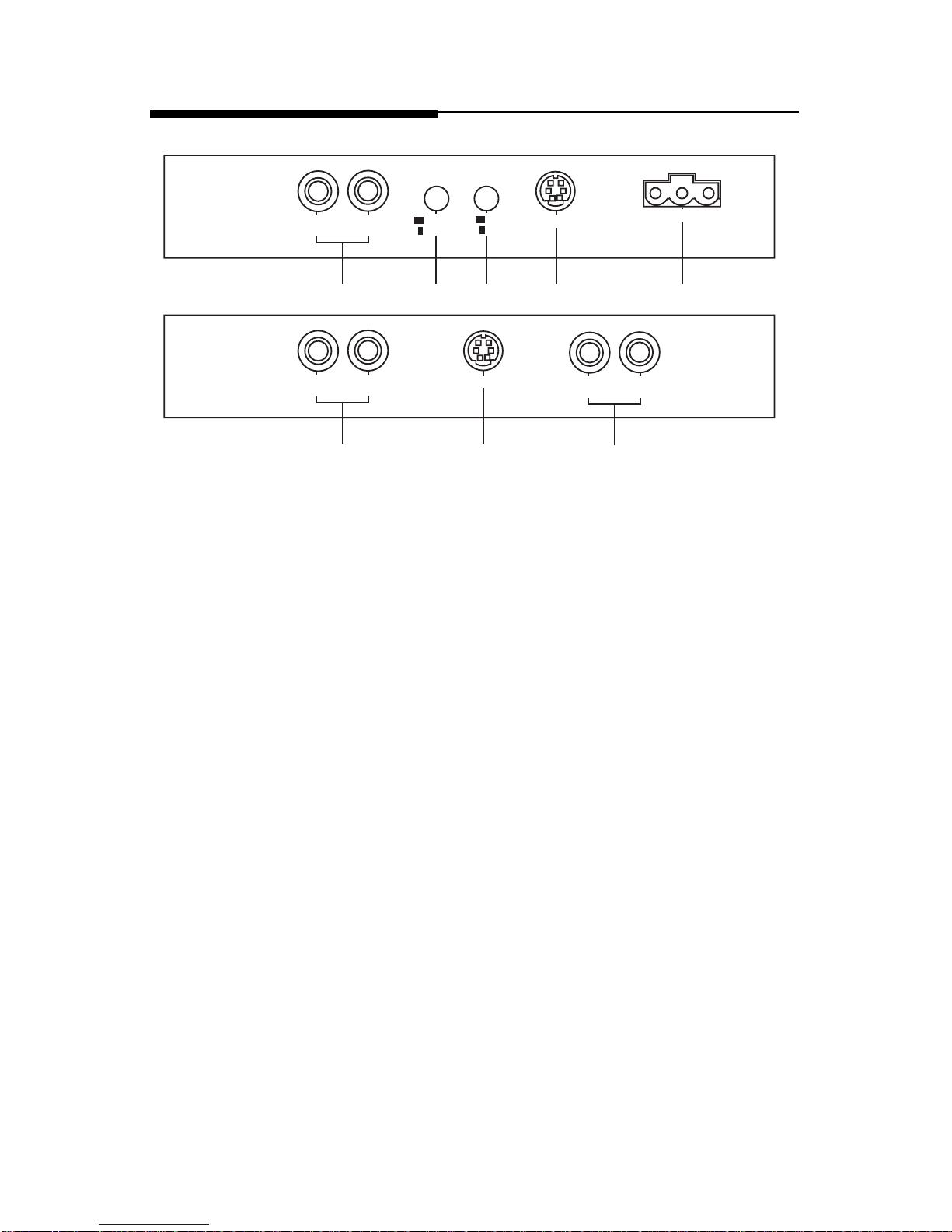
6
RIGHT LEFT
LEFTINRIGHT
IN
GND B+ REM
BAL INRCA
BAL
BYPASS
ENGAGE
1432 12
6
RIGHT LEFT
7
BAL OUT
1. RCA Input Jacks – The industry standard RCA jacks provide easy
connections for signal level input. They are gold-plated to resist the
signal degradation caused by corrosion.
2. Balanced Line Input – This input will allow the optional Balanced
Line Transmitter to be used for better noise rejection.
3. Signal Input Switch– This switch allows selection of either RCA or
Balanced Line inputs.
4. Engage/Bypass Switch – This switch enables the OEQ2 to process the
signal or bypass the Boost/Cut and Frequency Warp controls for a
“dry” output.
5. Input Sensitivity Controls – The input sensitivity controls are preset
for
500mV
which will match the output of most source units. They
can be adjusted to match input levels ranging from
500mV to 9.3V
.
6. RCA Output Jacks – The RCA Output Jacks provide a parallel output
and are used to connect the signal to the next component's input
jacks. They are gold-plated to resist the signal degradation caused by
corrosion.
7. Balanced Line Output – The balanced output allows a balanced line
cable to be used between the output of the OEQ2 and the input of the
next component to provide better noise rejection.
Page 7
– 4 –
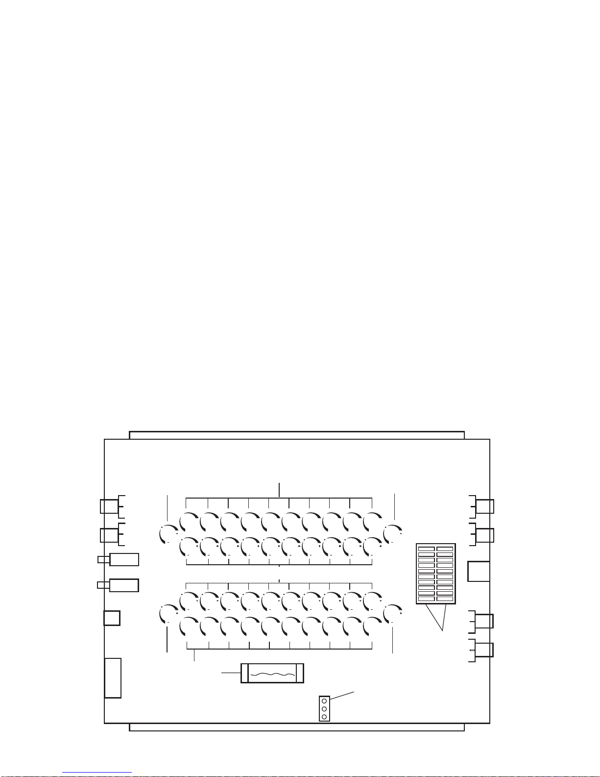
8. Output Level Attenuators – The Output Level Attenuators are
used to cut the output level for matching the input of the amplifier.
They can be adjusted to levels ranging from a minimum ratio of
1:0 (no output) to a maximum ratio of 1:1.
9. Boost/Cut Controls – These controls provide up to 12dB of boost
or cut to the selected frequency.
10. Frequency Warp Controls – These controls provide up to an
octave range (1/2 octave up and 1/2 octave down) from the center
frequency to pinpoint “dips” and “peaks”.
11. LED Level Indicators – The level indicators monitor the input level
of the OEQ2. The indicators utilize green, amber and red LEDs to
represent low, high and maximum signal level.
12. Power Connector – The power connector provides a convenient
connection for ground, power and remote. The connector uses
“screw lock” terminals to secure the power wires and is removable for quick disconnects.
13. B+ Fuse – The B+ fuse protects the power supply and battery from
short circuits and power failures.
14. DGND/AGND Jumper – This jumper is used for troubleshooting
systems which may exhibit noise due to ground loops or lack of
ground potential.
0
+
12
-12
0
+
12
-12
0
+
12
-12
0
+
12
-12
0
+
12
-12
0
+
12
-12
0
+
12
-12
0
+
12
-12
0
+
12
-12
0
+
12
-12
0
+
12
-12
0
+
12
-12
0
+
12
-12
0
+
12
-12
0
+
12
-12
0
+
12
-12
0
+
12
-12
0
+
12
-12
0
+
12
-12
0
+
12
-12
L
E
F
T
R
I
G
H
T
DGND
CHS
AGND
5
11
14
13
5
8
8
9
9
10
Page 8

– 5 –
INSTALLATION CONSIDERATIONS
This section focuses on some of the vehicle considerations for installing
your new OEQ2. Pre-planning your system layout and best wiring routes
will save installation time. When deciding how to lay out your new
system, be sure that each component will be easily accessible for making
adjustments.
Before beginning any installation, be sure to follow these simple rules:
1. Be sure to carefully read and understand the instructions before
attempting to install the OEQ2.
2. For safety, disconnect the negative lead from the battery prior to
beginning the installation.
3. For easier assembly, we suggest you run all wires prior to mounting
your OEQ2 in place.
4. Route all of the RCA cables close together and away from any high
current wires.
5. Use high quality connectors for a reliable installation and to minimize signal or power loss.
6. Think before you drill! Be careful not to cut or drill into gas tanks, fuel
lines, brake or hydraulic lines, vacuum lines or electrical wiring when
working on any vehicle.
7. Never run wires underneath the vehicle. Running the wires inside the
vehicle provides the best protection.
8. Avoid running wires over or through sharp edges. Use rubber or
plastic grommets to protect any wires routed through metal, especially the firewall.
9. ALWAYS protect the battery and electrical system from damage with
proper fusing. Install the appropriate fuseholder and fuse on the
+12V power wire within 18” (45.7 cm) of the battery terminal.
10. When grounding to the chassis of the vehicle, scrape all paint from
the metal to ensure a good, clean ground connection. Grounding
connections should be as short as possible and always be connected
to metal that is welded to the main body, or chassis, of the vehicle.
The following is a list of tools you will need for installing the OEQ
2
Red power wire Wire strippers
Blue remote turn-on wire Wire cutters
Black grounding wire Voltmeter
Electric hand drill w/assorted bits Jeweler's slotted screwdriver
Battery post wrench
Page 9

MOUNTING LOCATION
The mounting location for the OEQ2 should allow easy access to the
controls for making necessary adjustments. The OEQ2 will most likely be
adjusted only at the time of installation and will not need further
adjustment unless changes to the audio system are performed. To ensure
optimum performance, care should be taken when mounting the equal-
izer in the following locations:
Engine Compartment
Mounting the OEQ2 in the engine compartment will void your warranty.
The only thing that should be mounted in the engine compartment is that
big metal thing that makes the vehicle go fast.
Passenger Compartment Mounting
Mounting the equalizer in the passenger compartment will provide easy
access for making adjustments by ear. Select an area which is free from
excessive dirt or dust. If mounting under the seat, be sure the OEQ2 will
avoid misadjustment from driver or passenger seat movement.
Trunk Mounting
Mounting the equalizer in the trunk will provide easy access for making
adjustments with an RTA (Real Time Analyzer) and pink noise. Select an
area which will avoid possible damage or misadjustment from loading
and unloading items such as groceries, golf clubs and packages from the
trunk.
– 6 –
WIRING THE SYSTEM
For safety, disconnect the negative lead from the car battery prior to
beginning the installation.
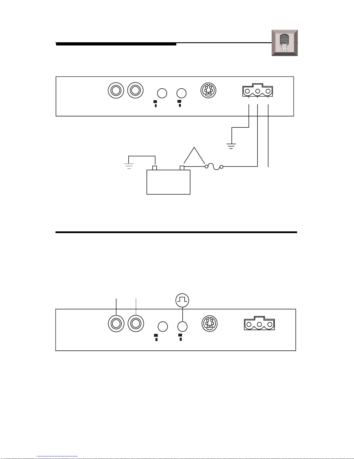
1. Wire the Power Connector
The B+ lead should be connected to a source of non-switched 12 volts
DC. Prepare a length of cable from the constant +12V by stripping 3/8"
of insulation from the end of the wire. Insert the bared wire into the B+
terminal of the power connector and fasten the screw.
NOTE: The B+ lead of the audio system MUST be fused 18" or less from
the vehicle's battery. Install a fuseholder, along with the necessary
fuse, under the hood. Connections should be water tight.
The REM lead should be connected to the remote turn-on or power
antenna output from the source unit. Prepare a length of cable from the
source of switched voltage by stripping 3/8" of insulation from the end
Page 10

of the wire. Insert the bared wire into the REM terminal of the power
connector and fasten the screw. Total current consumption through
this lead is negligible.
The GND lead should be connected to the chassis ground of the
vehicle. Prepare a length of cable (approximately 12" long) to be used
for the ground lead by stripping 3/8" of insulation from each end.
Insert one end of bared wire into the GND terminal of the power
connector and fasten the screw. Prepare the chassis ground by
scraping any paint from the metal surface and thoroughly clean the
area of all dirt and grease. Strip the other end of the wire and attach
a ring connector. Fasten the cable to the chassis using a non-anodized
screw and star washer.
2. Connect the Source Inputs
To accept RCA inputs, the signal input switch should be OUT.
Connect the front RCA outputs from the source unit to the “LEFT IN”
and “RIGHT IN” connectors on the OEQ2.
To accept Balanced Line Inputs, the signal input switch should be IN.
Connect the front RCA outputs from the source unit to the inputs on
the BLT. Connect the balanced line cable from the BLT to the “BAL
IN” connector on the OEQ2.
3. Connect the Outputs
Connect the appropriate outputs from the OEQ2 to the corresponding
inputs on the amplifier(s) or signal processor(s). For greater system
flexibility, all outputs from the OEQ2 are configured in parallel (refer
to the System Diagrams section of this manual for examples).
4. Adjust System Levels
Set the gain controls on the amplifier(s) as well as the input gain and
output attenuators on the OEQ2 to minimum. Adjust all Boost/Cut
and Frequency Warp controls to their center position. Adjust 1kHz
Boost/Cut to maximum. Using a 1kHz test tone recorded at ”0dB” or
“all bits high,” adjust the source unit for its maximum unclipped
output. Adjust the input sensitivity on the OEQ2 until the first red LED
on the OEQ2 starts to illuminate. Stop the test tone and do not readjust
the volume control. Readjust 1kHz on Boost/Cut to its center position.
Play a musical track with high dynamic content and adjust the output
attenuators on the OEQ2 to the desired output level (be sure Left and
Right channels are matched). Typically, the amplifier gain controls
will be left at minimum for optimum signal-to-noise ratio. For more
information on adjusting system levels, refer to the Installation
section of this manual.
– 7 –
Page 11
– 8 –
OEQ2 INSTALLATION
I
N
S
T
A
L
L
A
T
I
O
N
® ®
LEFTINRIGHT
IN
BAL INRCA
BAL
BYPASS
ENGAGE
Less than 18"
–
+
GND B+ REM
Power Connections
Connect to B+ of battery
with a 2 amp fuse.
Connect to chassis
ground of vehicle.
Connect to remote
turn-on lead of
source unit.
LEFTINRIGHT
IN
BAL INRCA
BAL
BYPASS
ENGAGE
GND B+ REM
RCA
Input
RCA Input Connections
• RCA Outputs from source connect to
LEFT IN
and
RIGHT IN
of OEQ
2
• Signal Input Switch is
out
for RCA Input
NOTE: DO NOT use RCA and Balanced Line Inputs simultaneously.
Page 12
– 9 –
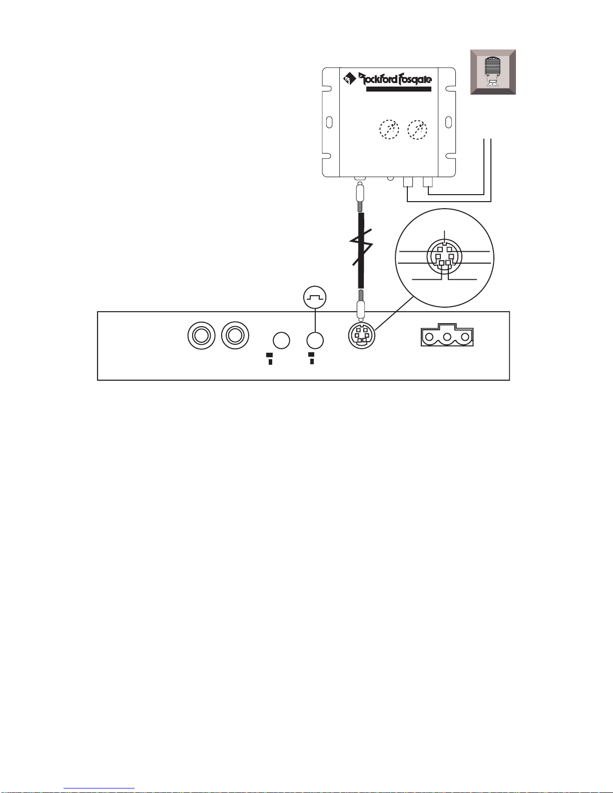
BLT Input Connections
• RCA Outputs from source connect to input of Balanced Line Transmitter
• Balanced Line Cable from BLT connects to
BAL IN
of OEQ
2
• Signal Input Switch is
pressed in
for balanced line input
NOTE: DO NOT use RCA and Balanced Line Inputs simultaneously.
LEFTINRIGHT
IN
BAL INRCA
BAL
BYPASS
ENGAGE
GND B+ REM
BALANCED LINE TRANSMITTER
INPUT
L R
BALANCED LINE
OUTPUT
®
®
LED
+ L Signal
Shield
+ R Signal
– R Signal
– L Signal
–15V+15V
RCA Input
I
N
S
T
A
L
L
A
T
I
O
N
® ®
Page 13

– 10 –
I
N
S
T
A
L
L
A
T
I
O
N
® ®
RCA Output Connections
BAL OUT
RIGHT LEFT
LEFTRIGHT
BAL OUT
RIGHT LEFT
RIGHT LEFT
+ L Signal
Shield
+ R Signal
– R Signal
– L Signal
NCNC
• Balanced Output connects to
balanced input
of next component
Balanced Output Connections
• RCA Outputs are configured in
parallel
• Use either RCA Output for
input
of next component
Page 14

Level Setting the OEQ
2
– 11 –
1. Set the Gain Controls on the amplifier(s) as well as the input gain and
output attenuators on the OEQ2 to
minimum
.
2. Adjust Boost/Cut and Frequency Warp Controls to their
center
position
3. Adjust 1k on OEQ2 to
maximum
boost (+12dB)
4. CD Software used to set levels is a test tone of 1kHz at “0dB” or
“All Bits High”
5. Adjust Source Unit to 3/4 volume (or maximum unclipped output)
6. Adjust Input Sensitivity on the OEQ2 until the first red LED illuminates
7. Stop Test Tone and do not readjust the volume control
8. Adjust 1k on OEQ2 back to its
center
position
9. Play Musical Track with high dynamic content
10. Adjust Output Attenuators on the OEQ2 to the desired output level
11. Leave Amplifier Gains at
minimum
for optimum signal-to-noise ratio
AUD
SEL
1 2 3 4 5 6
RDM
RPT
SCAN
PAUSE
D.SCN
DIM
AM
FM
Ch
RPTLD
RDM
DISC
ST
P.SCN LOUDDSPL
R
CLOCK
ILLUM
PWR
AUTO
® ®
VOL
TUNE
0
+
12
-12
0
+
12
-12
0
+
12
-12
0
+
12
-12
0
+
12
-12
0
+
12
-12
0
+
12
-12
0
+
12
-12
0
+
12
-12
0
+
12
-12
0
+
12
-12
0
+
12
-12
0
+
12
-12
0
+
12
-12
0
+
12
-12
0
+
12
-12
0
+
12
-12
0
+
12
-12
0
+
12
-12
0
+
12
-12
L
E
F
T
R
I
G
H
T
® ®
High Performance Parametric Equalizer
a
d
v
a
n
c
e
d
O
p
e
r
a
t
i
o
n
1kHz Test Tone @ “0dB”
Page 15

Level Setting the OEQ2 with a BLT
– 12 –
a
d
v
a
n
c
e
d
O
p
e
r
a
t
i
o
n
+
–
9.0
VAC
BALANCED LINE TRANSMITTER
®
®
1kHz Test Tone @ “0dB”
0
+
12
-12
0
+
12
-12
0
+
12
-12
0
+
12
-12
0
+
12
-12
0
+
12
-12
0
+
12
-12
0
+
12
-12
0
+
12
-12
0
+
12
-12
0
+
12
-12
0
+
12
-12
0
+
12
-12
0
+
12
-12
0
+
12
-12
0
+
12
-12
0
+
12
-12
0
+
12
-12
0
+
12
-12
0
+
12
-12
L
E
F
T
R
I
G
H
T
® ®
High Performance Parametric Equalizer
L
R
L
R
AUD
SEL
1 2 3 4 5 6
RDM
RPT
SCAN
PAUSE
D.SCN
DIM
AM
FM
Ch
RPTLD
RDM
DISC
ST
P.SCN LOUDDSPL
R
CLOCK
ILLUM
PWR
AUTO
® ®
VOL
TUNE
1. Set the Gain Controls on the amplifier(s) as well as the input gain and
output attenuators on the OEQ2 and BLT to
minimum
.
2. Adjust Boost/Cut and Frequency Warp Controls to their
center
position
3. Adjust 1k on OEQ2 to
maximum
boost (+12dB)
4. CD Software used to set levels is a test tone of 1kHz at “0dB” or
“All Bits High”
5. Adjust Source Unit to 3/4 volume (or maximum unclipped output)
6. Remove BLT Cover to access gain pots
7. Adjust BLT Gain to
9.0 VRMS
using an AC Voltmeter
8. Adjust Input Sensitivity on the OEQ2 until the first red LED illuminates
9. Stop Test Tone and do not readjust the volume control
10. Adjust 1k on OEQ2 back to its
center
position
11. Play Musical Track with high dynamic content
12. Adjust Output Attenuators on the OEQ2 to the desired output level
13. Leave Amplifier Gains at
minimum
for optimum signal-to-noise ratio
Page 16

– 13 –
OEQ2 OPERATION
Boost/Cut Control
The Boost/Cut controls are used to increase or reduce emphasis in a specific
octave of music. Each control provides up to 12dB of boost or cut to the
selected frequency. The following graph shows the effect of each control at
the full boost (+12dB) and full cut (–12dB) positions.
Hz
• Graph Illustrates each Boost/Cut control adjusted to –12dB,
0dB, and +12dB
d
B
r
Minimum
–12
+12
–12dB
0
–12
+12
0
Maximum
–12
+12
+12dB
Center
+0dB
0
Page 17

Frequency Warp Control
The Frequency Warp controls are used to fine adjust the center frequency of
the Boost/Cut controls. Each Warp control allows for a range of 1/2 octave
above and below the center frequency. The following graph illustrates the
operating range of the 1kHz Warp control at its minus (–), center (•), and plus
(+) positions.
– 14 –
• Graph Illustrates Frequency Warp of 1kHz adjusted to Minus, Center,
and Plus
Plus
–
+
(1.5kHz)
0
–
+
0
Minus
–
+
(750Hz)
Center
(1kHz)
0
Page 18

Engage/Bypass Switch
The Engage/Bypass Switch is useful in system tuning when comparing the
differences between an equalized and non-equalized system. With the
switch in the IN position, all EQ functions are engaged and can be heard.
With the switch in the OUT position, all EQ functions except the input gains
and output attenuators are bypassed from the signal path. In Bypass mode, the
OEQ2 can be used at the front of the system as a line driver. The signal from
the source unit is amplified with the OEQ2 input gains. This higher voltage
will help overcome noise which may be picked up in the cable. The higher
voltage results in a better signal-to-noise ratio at the amplifier's input.
• OEQ2 Bypass Mode allows all functions, except Input Gains and Output
Attenuators, to be
bypassed
• An Alternative Line Driver can be made with the OEQ2 by using it in
Bypass
mode and placing it near the
front of the signal chain
– 15 –
0
+
12
-12
0
+
12
-12
0
+
12
-12
0
+
12
-12
0
+
12
-12
0
+
12
-12
0
+
12
-12
0
+
12
-12
0
+
12
-12
0
+
12
-12
0
+
12
-12
0
+
12
-12
0
+
12
-12
0
+
12
-12
0
+
12
-12
0
+
12
-12
0
+
12
-12
0
+
12
-12
0
+
12
-12
0
+
12
-12
L
E
F
T
R
I
G
H
T
DGND
CHS
AGND
• OEQ2 Engage Mode allows
all EQ functions
to be heard
0
+
12
-12
0
+
12
-12
0
+
12
-12
0
+
12
-12
0
+
12
-12
0
+
12
-12
0
+
12
-12
0
+
12
-12
0
+
12
-12
0
+
12
-12
0
+
12
-12
0
+
12
-12
0
+
12
-12
0
+
12
-12
0
+
12
-12
0
+
12
-12
0
+
12
-12
0
+
12
-12
0
+
12
-12
0
+
12
-12
L
E
F
T
R
I
G
H
T
DGND
CHS
AGND
Engage
Bypass
Equalized Output
Full Range Output
20Hz 20kHz
20Hz 20kHz
Page 19

SYSTEM DIAGRAMS
RCA Input/RCA Output
– 16 –
0
+
12
-12
0
+
12
-12
0
+
12
-12
0
+
12
-12
0
+
12
-12
0
+
12
-12
0
+
12
-12
0
+
12
-12
0
+
12
-12
0
+
12
-12
0
+
12
-12
0
+
12
-12
0
+
12
-12
0
+
12
-12
0
+
12
-12
0
+
12
-12
0
+
12
-12
0
+
12
-12
0
+
12
-12
0
+
12
-12
L
E
F
T
R
I
G
H
T
® ®
High Performance Parametric Equalizer
AUD
SEL
1 2 3 4 5 6
RDM
RPT
SCAN
PAUSE
D.SCN
DIM
AM
FM
Ch
RPTLD
RDM
DISC
ST
P.SCN LOUDDSPL
R
CLOCK
ILLUM
PWR
AUTO
® ®
VOL
TUNE
®®
POWER
250
®
RCA Input
OEQ2 located in
front of vehicle
RCA Output
Tweeter
Midrange
Tweeter
Midrange
Page 20

RCA Input/Balanced Output
– 17 –
0
+
12
-12
0
+
12
-12
0
+
12
-12
0
+
12
-12
0
+
12
-12
0
+
12
-12
0
+
12
-12
0
+
12
-12
0
+
12
-12
0
+
12
-12
0
+
12
-12
0
+
12
-12
0
+
12
-12
0
+
12
-12
0
+
12
-12
0
+
12
-12
0
+
12
-12
0
+
12
-12
0
+
12
-12
0
+
12
-12
L
E
F
T
R
I
G
H
T
® ®
High Performance Parametric Equalizer
AUD
SEL
1 2 3 4 5 6
RDM
RPT
SCAN
PAUSE
D.SCN
DIM
AM
FM
Ch
RPTLD
RDM
DISC
ST
P.SCN LOUDDSPL
R
CLOCK
ILLUM
PWR
AUTO
® ®
VOL
TUNE
®®
POWER
250
®
RCA Input
OEQ2 located in
front of vehicle
Balanced
Output
Tweeter
Midrange
Tweeter
Midrange
Page 21

Balanced Input/RCA Output
– 18 –
0
+
12
-12
0
+
12
-12
0
+
12
-12
0
+
12
-12
0
+
12
-12
0
+
12
-12
0
+
12
-12
0
+
12
-12
0
+
12
-12
0
+
12
-12
0
+
12
-12
0
+
12
-12
0
+
12
-12
0
+
12
-12
0
+
12
-12
0
+
12
-12
0
+
12
-12
0
+
12
-12
0
+
12
-12
0
+
12
-12
L
E
F
T
R
I
G
H
T
® ®
High Performance Parametric Equalizer
BALANCED LINE TRANSMITTER
®
®
L
R
L
R
®®
POWER
250
®
®®
POWER
250
®
m
AUD
SEL
1 2 3 4 5 6
RDM
RPT
SCAN
PAUSE
D.SCN
DIM
AM
FM
Ch
RPTLD
RDM
DISC
ST
P.SCN LOUDDSPL
R
CLOCK
ILLUM
PWR
AUTO
® ®
VOL
TUNE
Optional Balanced
Line Transmitter
Balanced
Output
OEQ2 located in
rear of vehicle
RCA Output
Tweeter
Midrange
Woofers
Page 22

– 19 –
0
+
12
-12
0
+
12
-12
0
+
12
-12
0
+
12
-12
0
+
12
-12
0
+
12
-12
0
+
12
-12
0
+
12
-12
0
+
12
-12
0
+
12
-12
0
+
12
-12
0
+
12
-12
0
+
12
-12
0
+
12
-12
0
+
12
-12
0
+
12
-12
0
+
12
-12
0
+
12
-12
0
+
12
-12
0
+
12
-12
L
E
F
T
R
I
G
H
T
® ®
High Performance Parametric Equalizer
®
®®
4
BALANCED LINE TRANSMITTER
®
®
L
R
L
R
®®
POWER
250
®
®®
POWER
250
®
m
AUD
SEL
1 2 3 4 5 6
RDM
RPT
SCAN
PAUSE
D.SCN
DIM
AM
FM
Ch
RPTLD
RDM
DISC
ST
P.SCN LOUDDSPL
R
CLOCK
ILLUM
PWR
AUTO
® ®
VOL
TUNE
Balanced Input/RCA & Balanced Output
OEQ2 located in
rear of vehicle
Optional Balanced
Line Transmitter
RCA Output
RCA Output
Balanced Input
Woofers
Midbass
Tweeter
Midrange
Balanced
Output
Page 23

ROCKFORD FOSGATE ACCESSORIES
Balanced Line Transmitter (FG-BLT)
The Balanced Line Transmitter converts signal RCA cables from the
source unit to balanced signals. The BLT improves sound quality in the
system by eliminating noises generated by vehicle electrical systems.
The BLT is available for Rockford Fosgate products that offer a
balanced input.
®
Extra Balanced Cables (RP4205)
Additional 16' Balanced Line cables are available from the Connecting Punch line of Accessories.
– 20 –
®
ATTENTION: We recommend your Authorized Rockford Fosgate Dealer
install your new accessory.
LEFTINRIGHT
IN
GND B+ REM
BAL INRCA
BAL
BYPASS
ENGAGE
BALANCED LINE TRANSMITTER
®
®
NOISE
L
R
L
R
AUD
SEL
1 2 3 4 5 6
RDM
RPT
SCAN
PAUSE
D.SCN
DIM
AM
FM
Ch
RPTLD
RDM
DISC
ST
P.SCN LOUDDSPL
R
CLOCK
ILLUM
PWR
AUTO
® ®
VOL
TUNE
Page 24

TROUBLESHOOTING
Symptom Diagnosis Remedy
– 21 –
OEQ2 does not
turn on (Power
LED is off)
Check the alternator, battery, fuse and wiring and
repair as necessary. If the
voltage is above 15.5 volts,
have the electrical system
inspected by an authorized
car service center.
Check the alternator, battery, fuse, and wiring and
repair as necessary. If the
voltage is above 15.5 volts,
have the electrical system
inspected by an authorized
car service center.
Remove cover from OEQ
2
and replace with 2 Amp fuse.
Check wiring and repair as
necessary.
Check connections, substi-
tute with known working
source and cables, and repair or replace as necessary.
Check connections, substitute with known working
BLT cables and repair or replace as necessary.
Readjust output attenuators
as necessary.
Voltage applied to the
REM terminal of the
OEQ
2
is not between 5
and 15.5 volts.
Voltage to the B+ terminal of the OEQ2 is not
between 5 and 16 volts
or there is no voltage
present.
Internal B+ fuse is blown
OEQ2 is not properly
grounded.
OEQ2 has no sound
(Power LED is on)
RCA Input from source
unit is not connected or
not functioning properly.
When using the BLT,
Balanced Line Input from
BLT is not connected or
not functioning properly.
Output attenuators are at
minimum.
TROUBLE-
S
H
O
O
T
I
N
G
Page 25

– 22 –
Symptom Diagnosis Remedy
Turn-On Pop
Disconnect input signal to
OEQ
2
and turn OEQ2 on and
off. If noise is eliminated, connect REM lead of OEQ2 to
remote turn-on wire with a
delay module.
Readjust input gain of OEQ2
as necessary. Refer to Installa-
tion section of this manual for
proper level adjustment.
Readjust output attenuators as
necessary. Refer to Installa-
tion section of this manual for
proper level adjustment.
Check system with known
working source and repair or
replace original source as
needed.
Replace cables with known
good cables and repair or replace as necessary.
Check wiring and repair as
necessary or connect ground
to different location.
Check connections and run
the RCA cables on a different
route away from sources of
high current. If radiated noise
persists, use a BLT.
Voltage spike from output of preceding component is entering OEQ
2
through input signal
Input gains are incorrectly set.
Output attenuators set
to minimum or incorrectly set.
Source unit output too
low or source unit has
no output.
RCAs or BLT cable between source and OEQ
2
have bad or broken
ground shield.
Source unit is not properly grounded.
Noise is radiating into
RCA signal cable.
Distorted or Low
Output
TROUBLE-
S
H
O
O
T
I
N
G
Several LEDs
illuminating with
no music playing
Engine Noise
Page 26

Symptom Diagnosis Remedy
Check connections and bypass
additional components (crossovers and preamps) between
the source unit and the amplifier. Connect one component
at a time using muting plugs
(RCA signal shorted to shield)
at the input of each added component to determine the culprit. Repair or replace components as necessary.
Check ground connections
and connect amplifiers, signal
processors, and other components to a central location or
try a different grounding point
on the chassis.
Use only RCA or BLT input at
one time.
Remove the cover from the
OEQ
2
and locate jumper J1,
labeled DGND and AGND,
next to the transformer (round
donut with wires). This jumper
applies ground to the chassis
of the OEQ2. There are three
possible connections:
A. No Jumper Connection –
no ground applied to the
chassis
B. DGND – power supply
ground applied to chassis
C. AGND – RCA shield ap-
plied to chassis
Experiment with these jumper
configuration options until a
reduction in noise is observed.
Select the Signal Input Switch
for “BAL” input.
– 23 –
Engine Noise
• If noise persists, see your Authorized Rockford Fosgate Dealer.
TROUBLE-
S
H
O
O
T
I
N
G
Bad component in the
signal chain.
Multiple grounds in the
audio system.
RCA and BLT inputs are
utilized simultaneously.
Noise is entering the
system via a possible
ground loop.
Jumper Placement
Diagrams
Engine Noise
(BLT Input)
Signal Input switch not
selected for BLT input.
•
•
•
•
•
•
•
•
•
A.
DGND
Chass
AGND
DGND
Chass
AGND
DGND
Chass
AGND
C.
B.
Page 27

Operating Voltage +10V to +16VDC
Current Consumption 500mA
B+ Fuse Size (internal) 2 Amp
Fuse Type AGC
Frequency Response 20-20kHz ±0.1dB
Signal-to-Noise Ratio >98dBA
Distortion (THD + Noise) 0.02%
Input Impedance 20kΩ
Output Impedance 51Ω
Input Voltage 9.3 VRMS max
Output Voltage 9.3 VRMS max
Number of Channels 2
Number of Inputs 2 RCA or 1 Balanced
Number of Outputs 4 RCA and 1 Balanced (all paralleled)
Octave Centers 31, 62, 125, 250, 500, 1k, 2k, 4k, 8k, 16k
Level Adjustment Range ±12dB
Frequency Warp Range ±1/2 octave (from center frequency)
Dimensions 6"W x 73⁄4"L x 11⁄8"H
(without mounting flange) (15.2cm x 19.7cm x 2.9cm)
Dimensions 7"W x 73⁄4"L x 11⁄8"H
(with mounting flange) (17.8cm x 19.7cm x 2.9cm)
– 24 –
SPECIFICATIONS
Specifications are subject to change without notice.
Page 28

Rockford Fosgate warrants all electronics to the original consumer/purchaser to be free
from defects in materials or workmanship for a period of three (3) years. We will cover
parts and labor provided the product was purchased from an Authorized Rockford
Fosgate Dealer. This warranty does not apply to any product on which the seals and/
or serial number have been broken, removed, tampered with, defaced or altered in any
manner. This warranty only applies to the original consumer/purchaser and is not
transferable.
Electronics found to be defective during the warranty period will be repaired or
replaced at Rockford Fosgate’s discretion. Repaired or replaced electronics will be
covered by the balance of the original warranty period only. Rockford Fosgate shall
not be responsible for any incidental or consequential damages resulting from a defect
in electronics. Some states do not allow the exclusion or limitation of incidental or
consequential damages, so the previous limitation may not be applicable.
The warranty does not cover any appearance item, any cost or expense related to the
removal or reinstallation of the product, any accessory used in conjunction with the
product, damage to the product resulting from alteration, accident, misuse or abuse,
or improper installation. This warranty does not apply if the parts or labor, which would
otherwise be provided without charge under this warranty, are obtained from any
source other than Rockford Fosgate or an Authorized Rockford Fosgate Service Center.
This warranty is the only express warranty and does not create any implied warranties.
Rockford Fosgate limits its obligations under any implied warranties under state laws
to a period not to exceed the written warranty period. Some states do not allow
limitation on how long an implied warranty lasts, so the above limitation may not
apply. This warranty applies only to products sold in the United States of America or
its possessions. For warranty outside the U.S.A., please contact the nearest Authorized
Rockford Fosgate Dealer. This warranty gives the consumer specific legal rights, and
the consumer may have other rights which vary from state to state.
A defective product must be shipped prepaid to the Authorized Rockford Fosgate
Dealer from which the consumer purchased the product or to the Rockford Fosgate
factory in Tempe, Arizona in the original factory carton or equivalent. Any shipping
loss or damage will be borne by the consumer or the consumer’s shipper. A consumer
returning a product to the factory must call (800) 669-9899 for a Return Authorization
Number. All shipments shall be clearly marked with the Return Authorization Number
on the outside of the shipping carton.
Ship to:
Rockford Corporation
Warranty Repair Department
2055 E. 5th Street
Tempe, AZ 85281 U.S.A.
Return Authorization Number:_________________
WARRANTY INFORMATION
– 25 –
Page 29

INTERNATIONAL
INFORMATION
– 26 –
Page 30

– 27 –
Lea detenidamente las siguientes instrucciones de instalación del producto.
INTRODUCCIÓN
El OEQ2 es un ecualizador de octava que se ha de utilizar para
compensar las inexactitudes acústicas comunes en el interior de los
automóviles. El OEQ2 es un ecualizador estereo con ajustes en diez
bandas de frecuencia espaciadas en intervalos de una octava. Cada
banda puede realzar o atenuar hasta 12dB para subsanar los picos o
valles de la respuesta frecuencial. Los controles Frequency Vary le
permiten desplazar la frecuencia central de cada banda hasta en
media octava hacia arriba o hacia abajo para un control más preciso.
Las ganancias de entrada y salida se han de utilizar para un ajuste
perfecto de niveles, con la ayuda de una pareja de monitores LED. El
OEQ2 es un ecualizador versatil que le ayundará a sacar el mejor
rendimiento de su sistema.
CABLEADO DEL SISTEMA
Por seguridad, desconecte el cable negativo de bateria antes de
comenzar la instalación.
Cableado del conector
El terminal B+ debe ser conectado a una fuente no conmutada de 12V
continuous. Prepare un cable de la longitud adecuada desde la fuente
de 12V+ y pele 1cm de aislante del cable en el extremo que vaya a
conectar al aparato. Inserte el cable pelado en el orificio B+ del
conector y asegúrelo con el tornillo.
NOTA: El terminal B+ de sistema de audio debe estar protegido con
un fusible no más lejos de 45cm de la bateria. Instale un portafusibles
y el correspondiente fusible en el compartimento del motor. Las
conexiones deben ser resistentes al agua.
El terminal REM ha de conectarse al terminal remote o antena de su
radio-cassette. Prepare un cable de la longitud adecuada desde la
fuente y pele 1cm de aislante del cable en el extremo que vaya a
conectar al aparato. Inserte el cable pelado en el orificio REM del
conector y asegúrelo con el tornillo. El consumo de corriente de este
terminal es despriciable.
El terminal GND ha de conectarse al chasis del vehiculo. Prepare un
cable de la longitud adecuada (mejor no más de 30cm) y pele 1cm
de aislante del cable en el extremo que vaya a conectar al aparato.
Inserte el cable pelado en el orificio GND del conector y asgúrelo con
el tornillo. Antes de conectar a chasis elimine la pintura de la
superficie del metal y limpie la superficie de polvo y grasa. Pele el otro
extremo del cable y añádale un conector de anillo. Asegure el cable
al chasis con un tornillo no anodizado.
Page 31

INSTALACION DEL OEQ
2
LEFTINRIGHT
IN
BAL INRCA
BAL
BYPASS
ENGAGE
GND B+ REM
BALANCED LINE TRANSMITTER
INPUT
L R
BALANCED LINE
OUTPUT
®
®
LED
+ L Signal
Shield
+ R Signal
– R Signal
– L Signal
–15V+15V
RCA Input
– 28 –
ESPAÑOL
Conexiones de entrada RCA
LEFTINRIGHT
IN
BAL INRCA
BAL
BYPASS
ENGAGE
GND B+ REM
• Conecte las salidas RCA de su fuente de sonido a las entradas LEFT
IN y RIGHT IN del OEQ
2
• El conmutador SIGNAL INPUT ha de estar no pulsado cuando utilice
entradas RCA
Conexiones de entrada BLT
• Conecte las salidas RCA de su fuente a la entrada del transmisor de linea
balanceada
• Conecter el cable de salida de linea balanceada a la entrada BAL del OEQ
2
• El conmutado SIGNAL INPUT ha de estar pulsado cuando utilice entradas BLT
NOTA: No use las entradas RCA y BLT simultáneamente.
Entrada
RCA
Page 32

– 29 –
Veuillez lire les instructions suivantes pour l'installation de ce produit. Ne
pas les suivre pourrait causer des blessures ou endommager le véhicule.
INTRODUCTION
L'OEQ2 est un égaliseur d'octave destiné à compenser les différences
acoustiques dans l'environnement automobile. C'est un égaliseur
stéréo avec 10 bandes de fréquence espacées à des intervalles
réguliers d'une octave. Chaque bande peut être amplifiée ou attenuée
de 12dB. Pour permettre l'ajustement fin de la courbe de réponse,
chaque fréquence est variable d'une demi octave vers le haut ou vers
le bas vis-à-vis de la fréquence de centre. Les gains d'entrée et de
sortie sont réglables séparément. L'appareil est équipé d'un affichage
LED indiquant le niveau d'entrée. L'OEQ2 est un égaliseur polyvalent
aux caractéristiques performantes pour affiner et résoudre les
problèmes de réponse de votre système.
CABLAGE DU SYSTÈME
Pour votre sécurité, veuillez déconnecter le pôle négatif de la batterie
avant de commencer l'installation.
Câblage du connecteur d'alimentation
La position B+ doit être connectée à un positif 12 volt permanent.
Coupez à bonne longueur le câble venant de la batterie et dénudez
le sur environ 2 cm. Introduisez la partie dénudée dans le terminal B+
du connecteur d'alimentation et serrez la vis.
ATTENTION: Le conducteur B+ du système audio doit être muni
d'un fusible le plus près possible de la batterie du véhicule. Installez
le porte-fusible sous le capot moteur. Les connections doivent être
étanches.
La position REM doit être connectée à la sortie antenne électrique de
l'appareil radio. Coupez à bonne longueur le câble venant de la radio
et dénudez le sur environ 2 cm. Introduisez la partie dénudée dans le
terminal REM du connecteur d'alimentation et serrez la vis. La
consommation de courant de cette entrée est négligeable.
La position GND doit être connectée au chassis du véhicule. Coupez
à bonne longueur le câble venant du chassis et dénudez le sur environ
2 cm. Introduisez la partie dénudée dans le terminal GND du
connecteur d'alimentation et serrez la vis. Pour obtenir un bon
contact de masse au chassis, grattez la peinture à l'endroit de la
connection et dégaissez-le ensuite. Attachez le cable avec une cosse
ronde, une vis galvanisée et une rondelle étoile.
Page 33

INSTALLATION DU OEQ
2
Connections d'entrée RCA
LEFTINRIGHT
IN
BAL INRCA
BAL
BYPASS
ENGAGE
GND B+ REM
• Les sorties RCA de la source se branchent sur l'entrée LEFT IN
(gauche) et RIGHT IN (droite) du OEQ
2
• Le commutateur de signal d'entrée doit être en position sortie
Connections d'entrée BLT
LEFTINRIGHT
IN
BAL INRCA
BAL
BYPASS
ENGAGE
GND B+ REM
BALANCED LINE TRANSMITTER
INPUT
L R
BALANCED LINE
OUTPUT
®
®
LED
+ L Signal
Shield
+ R Signal
– R Signal
– L Signal
–15V+15V
RCA Input
• Les sorties RCA de la source se branchent sur l'entrée du BLT
• Le câble balancé du BLT se connecte sur l'entrée BAL IN du OEQ
2
• Le commutateur de signal d'entrée doit être enfoncé
ATTENTION: Ne pas brancher les entrées RCA et BLT simultanément.
Entrée
RCA
– 30 –
FRANÇAIS
Page 34

Bitte lesen Sie die folgende Gebrauchsanleitung sorgfältig durch. Dies kann
Sie und das Produkt vor Fehlern oder sogar vor Beschädigung schützen.
EINLEITUNG
Der OEQ2 ist ein parametrischer Equalizer der Akustische Probleme
Ihrer Anlage oder Ihres Fahrzeuges ausbessern soll. Der OEQ2 ist ein
10 Band Stereo Equalizer bei dem einzeine Frequenzbänder, unterteilt
in interval-Oktaven eingestellt werden kônnen. Jedes Band kann um
plus-oder minus 12dB verändert werden, um so Probleme des
Frequenzverlaufes zu korrigieren. Die Frequenz-Kontrolle erlaubt
Ihnen die jeweilige Frequenz um eine 1/2 Oktave anzuheben oder
abzusenken. Eingangs- und Ausgangs-Pegelregler erlauben Ihnen,
den OEQ2 optimal an Ihre Anlage einzupassen. So übernimmt der
OEQ2 die Feinabstimmung Ihrer Anlage und hilft Ihnen einen möglichst
geraden Frequenzgang zu haben.
ANSCHLUβ DES OEQ
2
Anschluβ des Stromsteckers
Der B+ Anschluβ sollte mit einem Dauerplus Ihres Fahrzeuges
verbunden werden. Verwenden Sie ein Kabel das konstant 12 Volt hat
und isolieren es am Ende ca. einen 1/2 cm ab. Stecken Sie es dann in
das B+ Terminal und ziehen die Schraube fest.
Achtung: Das B+ Kabel Mub 46cm nach der Stromaufnahme
abgesichert sein. Installieren Sie einen Sicherungshalter mit der
passenden Sicherung und stellen Sie sicher das er Spritzwasser
geschützt ist.
Die Einschaltleitung sollten Sie von der Remote-oder Antennenspannung Ihres Radios abgreifen. Isolieren Sie es ca. einen 1/2 cm am
Ende des Kabels ab und schrauben es im Remote-Terminal fest Die
Spannung die in diesem Kabel fliebt ist sehr gering.
Das Erdungskabel sollte direkt mit der Erdung des Fahrzeuges
verbunden werden. Das Kabel sollte nicht länger wie 30 cm sein.
Isolieren Sie wieder das Ende ab und schrauben es im Ground
Terminal des OEQ2 fest. Der Erdungspunkt an Ihrem Fahrzeug sollte
Lackfrei und sauber sein. Dort sollten Sie dann das andere Ende des
Erdungskabels befestigen. Stellen Sie sicher das Sie einen guten
Massepunkt wahlen.
– 31 –
Zur Sicherheit klemmen Sie den Negativ-Pol Ihrer Batterie ab.
Page 35

DEUTSCH
OEQ2 EINBAU
Chinch-Eingangs Buchsen
LEFTINRIGHT
IN
BAL INRCA
BAL
BYPASS
ENGAGE
GND B+ REM
• Chinch-Ausgänge der Signalquelle rechts und links mit right in und
left in verbinden
• Signal-Eingangsschalter auf out für Chinch-Eingang stellen
BLT Eingang
LEFTINRIGHT
IN
BAL INRCA
BAL
BYPASS
ENGAGE
GND B+ REM
BALANCED LINE TRANSMITTER
INPUT
L R
BALANCED LINE
OUTPUT
®
®
LED
+ L Signal
Shield
+ R Signal
– R Signal
– L Signal
–15V+15V
RCA Input
• Chinch Ausgang der Signalquelle mit dem BLT verbinden
• Balanced Line Kabel vom BLT mit Bal in des OEQ2 verbinden
• Signal-Eingangsschalter auf in für Balanced Line Input stellen
Achtung: Verwenden Sie niemals Chinch-und Balanced Line Kabel gemeinsam
Chinch
Eingänge
– 32 –
Page 36

Leggere attentamente le istruzioni riportate in questo manuale. Non osservare
le correte procedure di impiego puó provacare danni al veicolo o a voi stessi.
CABLARE IL SISTEMA
Per sicurezza, disconnettere il cavo negativo dalla batteria prima di
iniziare l'installazione.
Cablare il connettore di alimentazione.
Alla terminazione siglata B+ connettere un cavo spellato per circa
8mm inserendolo nel foro apposito e fermandolo serrando la vite.
Collegare l'altra estremitá del cavo ad un polsitivo costante (sempre
presente) dell'auto.
NOTA: Il cavo positivo del sistema audio deve essere protetto da un
fusibile posto a non piú di 40cm dalla terminazione positiva della
batteria e deve essere a tenuta d'acqua.
Alla terminazione REM connettere un cavo proveniente dal remote
dell'autoradio (es. antenna elettrica). Il consumo di corrente é
assolutament trascurabile.
Alla terminazione GND connettere un cavo opportunamente portato
alla massa del telaio deve essere pulito dalla vernice e da eventuali
grassi o siliconi ed il cavo deve essere solidamente fissato ipiegando
un terminale ad anello ed una vite non anodizzata.
INTRODUZIONE
OEQ2 é un equalizzatore ad ottave impiegato per compensare i difetti
acustici tipici dell'interno delle automobili. OEQ2 é un equalizzatore
stereo con 10 bande di interveno spaziate ad ottave. Ciascuna banda
puó arrivare ad un'esaltazione od attenuazione massime di 12dB per
compensare picchi o buchi nella curva di risposta. Per ciascuna
banda puó essere regolato con massima precisione il punto di
intervento, spostandolo di ±1/2 ottave, con il controllo Frequency
Warp. Per un ottimale interfacciamento sono previsti controlli di
livello di ingresso e di uscita separati ed una comoda barra LED per
controllare lo stadio di ingresso. OEQ2 é un versatile equalizzatore
con ottime caratteristiche che permettono di tarare il sistema alla
perfezione e di compensare i problemi di risposta dell'auto.
– 33 –
Page 37

INSTALLAZIONE DELL'OEQ
2
Connessione degli ingressi RCA
LEFTINRIGHT
IN
BAL INRCA
BAL
BYPASS
ENGAGE
GND B+ REM
• Le uscite RCA della sorgente vengono collegate agli ingressi LEFT IN
e RIGHT IN dell'OEQ
2
• Lo switch deve essere nella posizione RCA (rilasciato)
Connessione dell'ingresso
bilanciato BLT
LEFTINRIGHT
IN
BAL INRCA
BAL
BYPASS
ENGAGE
GND B+ REM
BALANCED LINE TRANSMITTER
INPUT
L R
BALANCED LINE
OUTPUT
®
®
LED
+ L Signal
Shield
+ R Signal
– R Signal
– L Signal
–15V+15V
RCA Input
Intresso
RCA
ITALIANO
– 34 –
• Le uscite RCA della sorgente vengono collegate agli ingressi del Bal-
anced Line Transmitter BLT (fornito a parte)
• Il cavo bilanciato del BLT vieve connesso all'ingresso BAL IN dell'OEQ
2
• Lo switch deve essere nella posizione BAL (premuto).
NOTA: Non impiegare gli ingressi bilanciati ed RCA contemporaneamente.
Page 38

NOTES
Page 39

NOTES
Page 40

Rockford Fosgate
Rockford Corporation
546 South Rockford Drive
Tempe, Arizona 85281 U.S.A.
In U.S.A., (602) 967-3565
In Europe, Fax (49) 4207-801250
In Japan, Fax (81) 559-79-1265
2/96
MAN-1135-A
 Loading...