

Rockford Fosgate Marine M400-4D, Marine M600-4D, Prime M400-4D, Prime M600-4D Installation & Operation Manual

I
NTRODUCTION
Dear Customer,
Congratulations on your purchase of the world's finest brand of car audio amplifiers. At Rockford Fosgate we are
fanatics about musical reproduction at its best, and we are pleased you c hose our product.Through years of engineering expertise, hand craftsmanship and critical testing procedures, we have created a wide range of products
that reproduce music with all the clarity and richness you deserve.
For maximum performance we recommend you have your new Rockford Fosgate product installed by an
Authorized Rockford Fosgate Dealer, as we provide specialized training through RockfordTechnicalTraining Institute
(RTTI). Please read your warranty and retain your receipt and original carton for possible future use.
Great product and competent installations are only a piece of the puzzle when it comes to your system. Make sure
that your installer is using 100% authentic installation accessories from Rockford Fosgate in your installation.
Rockford Fosgate has everything from RCA cables and speaker wire to power wire and battery connectors.
Insist on it! After all, your new system deserves nothing but the best.
To add the finishing touch to your new Rockford Fosgate image order your Rockford accessories, which include
everything from T-shirts to jackets.
To get a free brochure on Rockford Fosgate products and Rockford accessories,
visit our web site at: www.rockfordfosgate.com
or, in the U.S. call 1-800-669-9899 or FAX 1-800-398-3985.
For all other countries, call +001-480-967-3565 or FAX +001-480-966-3983.
PRACTICE SAFE SOUND™
Continuous exposure to sound pressure levels over 100dB may cause permanent
hearing loss. High powered auto sound systems may produce sound pressure levels well
over 130dB. Use common sense and practice safe sound.
If, after reading your manual, you still have questions regarding this product, we recommend that you see
your Rockford Fosgate dealer. If you need further assistance, you can call us direct at
1-800-669-9899. Be sure to have your serial number, model number and date of purchase available when
you call.
The serial number can be found on the outside of the box. Please record it in the space provided below as
your permanent record.This will serve as verification of your factory warranty and may become useful in
recovering your unit if it is ever stolen.
Serial Number: ______________________________________
Model Number: _____________________________________
T
ABLE OFCONTENTS
Introduction ......................2
SafetyInstructions.................3
DesignFeatures ...................4
Installation......................5-7
InstallationConsiderations..............5
MountingLocations....................5
BatteryandCharging ..................6
WiringtheSystem.....................6
Operation.........................8
AdjustingGain........................8
Adjusting Crossover Frequency . . . . . . . . . . 8
2/4ChannelSwitch....................8
PunchEQ............................8
Troubleshooting...................9
Specifications ....................10
Limited Warranty Information .....11
NOTE: Review each section for more detailed information.
© 2012 Rockford Corporation. All rights reserved.
Rockford Fosgate, the Rockford Fosgate logo, and the PRIME logo are either
registered trademarks or trademarks of Rockford Corporation.
2
GETTING STARTED
Welcome to Rockford Fosgate! This manual is designed to provide information for the owner,
salesperson and installer. For those of you who want quick information on how to install this product,
please turn to the Installation Section of this manual. Other information can be located by using the
Table of Contents.We, at Rockford Fosgate, have worked very hard to make sure all the information in
this manual is current. But, as we are constantly finding new ways to improve our product, this
information is subject to change without notice.
S
AFETYINSTRUCTIONS
This symbol with “WARNING” is intended to alert the user to the
presence of important instructions. Failure to heed the instructions
will result in severe injury or death.
This symbol with “CAUTION”isintendedtoalerttheusertothe
presence of important instructions. Failure to heed the instructions
canresultininjuryorunitdamage.
CAUTION: To prevent injury and damage to the unit, please read and follow the
instructions in this manual.We want you to enjoy this system, not get a
headache.
CAUTIONIf you feel unsure about installing this system yourself, have it installed by a
qualified Rockford Fosgate technician.
CAUTIONBefore installation, disconnect the battery negative (-) terminal to prevent
damage to the unit, fire and/or possible injury.
C
ONTENTS OFCARTON
A Marine M400-4D or M600-4D 4 Channel
Amplifier
Installation & Operation Manual
Mounting Hardware Kit
The hardware kit included with each amplifier contains the mounting hardware necessary to secure the
amplifier to the vehicle.
Visit our web site for the latest information on all Rockford products.
www.rockfordfosgate.com
3
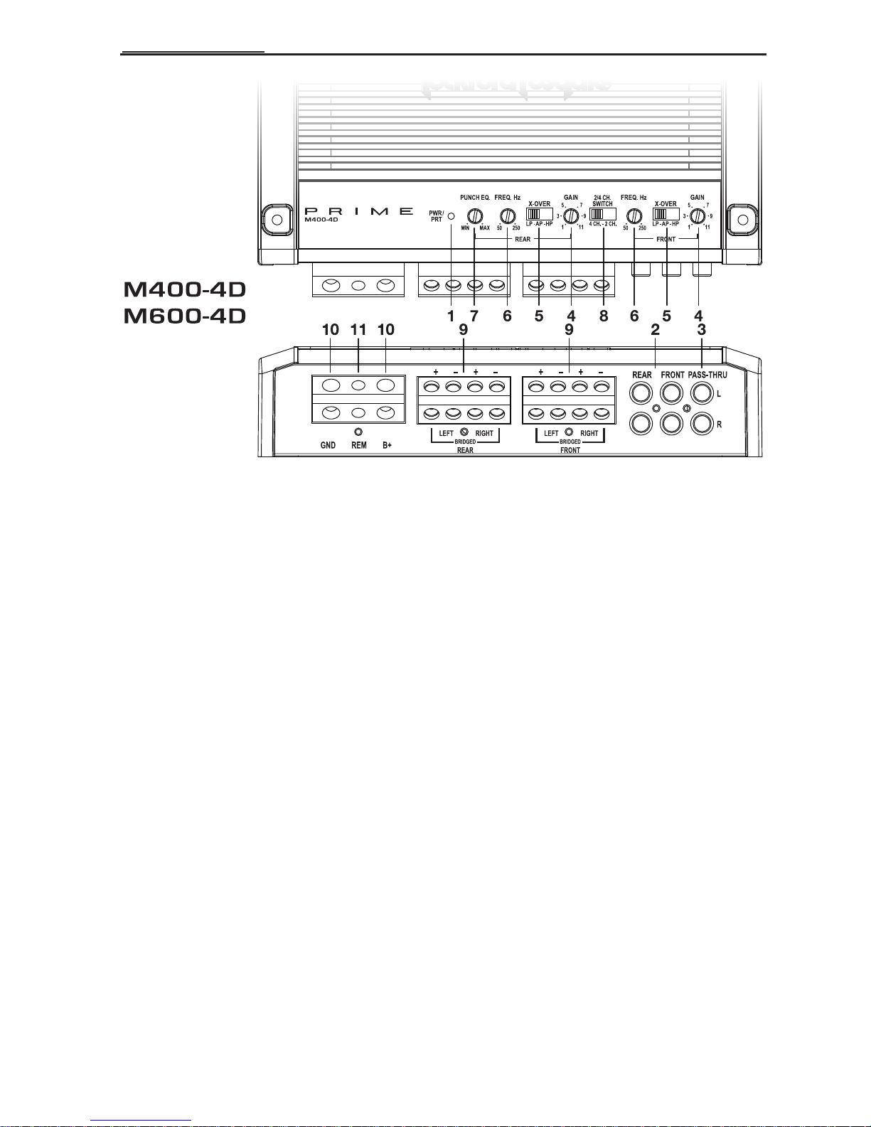
D
ESIGNFEATURES
1. Power/Protect LED – Power LED illuminates blue when the unit is turned on. Protect LED
illuminates red if a short circuit or to low of an impedance is detected at the speaker connections.The
amplifier will automatically shut down if this occurs.
2. RCA Input Jacks – The industry standard RCA jacks provide an easy connection for signal level input.
They are nickel-plated to resist the signal degradation caused by corrosion.
3. RCA Pass-Thru Jacks – This Pass-Thru provides a convenient source for daisy-chaining an additional
amplifier without running an extra set of RCA cables from the front of the vehicle to the rear amplifier
location.
4. Gain Control – The input gain control is preset to match the output of most source units.
5. Crossover Switch – Selectable switch for High-Pass (HP),All Pass (AP), or Low-Pass (LP) operation.
6. Variable Crossover – Is a built-in 12dB/octave Butterworth filter with a crossover point variable
from 50Hz to 250Hz.
7. Punch EQ – A Gyrator based Punch EQ that eliminates frequency shift with boost.This works along
with the crossover switch on the amplifier.When set to Low-Pass (LP) operation, this control is a narro w
band adjustment variable from 0dB to +18dB @ 45Hz.
8. 2/4 Channel Switch – Setting this switch to the 2CH. position, switches the inputs to a 2-channel
mode, allowing connection to only the front inputs with a 4-channel output.
9. Speaker Terminals – The heavy duty, nickel-plated set-screw wire connectors (+and -)will
accommodate 8 AWG.
10. Power Terminals – The power and ground are nickel-plated set-screw wire connectors and will
accommodate 4 AWG.
11. REM Terminal – The nickel-plated set-screw wire connector and will accommodate 8 AWG.This
terminal is used to remotely turn-on and turn-off the amplifier when +12V DC is applied.
4
 Loading...