

Rockford Fosgate Fanatic P FNP1414, Fanatic P FNP1514, Fanatic P FNP1614F, Fanatic P FNP1614 Operating & Installation Manual
Page 1

component systems
® ®
car audio
fanatics
for
operation &operation &
operation &operation &
operation &
installationinstallation
installationinstallation
installation
Page 2

Dear Customer,
Congratulations on your purchase of the world's finest brand of car audio speakers. At
Rockford Fosgate we are fanatics about musical reproduction at its best, and we are
pleased you chose our product. Through years of engineering expertise, hand craftsmanship and critical testing procedures, we have created a wide range of products that
reproduce music with all the clarity and richness you deserve.
For maximum performance we recommend you have your new Rockford Fosgate
product installed by an Authorized Rockford Fosgate Dealer, as we provide specialized
training through Rockford Technical Training Institute (RTTI). Please read your
warranty and retain your receipt and original carton for possible future use.
Great product and competent installations are only a piece of the puzzle when it comes
to your system. Make sure that your installer is using 100% authentic installation
accessories from Connecting Punch in your installation. Connecting Punch has
everything from RCA cables and speaker wire to Power line and battery connectors.
Insist on it! After all, your new system deserves nothing but the best.
To add the finishing touch to your new Rockford Fosgate image order your Rockford
wearables, which include everything from T-shirts and jackets to hats and sunglasses.
To get a free brochure on Rockford Fosgate products and Rockford accessories, in the
U.S. call 602-967-3565 or FAX 602-967-8132. For all other countries, call +001-602967-3565 or FAX +001-602-967-8132.
If, after reading your manual, you still have questions regarding this product,
we recommend that you see your Rockford Fosgate dealer. If you need further
assistance, you can call us direct at 1-800-669-9899. Be sure to have your serial
number, model number and date of purchase available when you call.
PRACTICE SAFE SOUND™
CONTINUOUS EXPOSURE TO SOUND PRESSURE LEVELS OVER 100dB
MAY
CAUSE PERMANENT HEARING LOSS. HIGH POWERED AUTOSOUND
SYSTEMS
MAY PRODUCE SOUND PRESSURE LEVELS WELL OVER
130dB. USE COMMON SENSE AND PRACTICE SAFE SOUND.
The serial number can be found on the outside of the box. Please record it in
the space provided below as your permanent record. This will serve as
verification of your factory warranty and may become useful in recovering your
product if it is ever stolen.
Serial Number: ________________________________
Model Number:________________________________
Page 3

Welcome to Rockford Fosgate! This manual is designed to provide information
for the owner, salesperson and installer. For those of you who want quick
information on how to install this product, please turn to the
Installation
Section
of this manual or refer to the icons listed below. Other information can
be located by using the Table of Contents. We, at Rockford Fosgate, have
worked very hard to make sure all the information in this manual is current. But,
as we are constantly finding new ways to improve our product, this information
is subject to change without notice.
G
ETTING
S
TARTED
Sections marked
TROUBLESHOOTING
include recommendations for
curing
installation problems
I
N
S
T
A
L
L
A
T
I
O
N
® ®
TROUBLE-
S
H
O
O
T
I
N
G
T
ABLE OF
C
ONTENTS
Introduction................................................................................................1
Package Contents ....................................................................................... 1
Design Features .......................................................................................... 2
Installation Considerations ...........................................................................4
Mounting Location ...................................................................................... 5
Installation ................................................................................................. 6
Troubleshooting.......................................................................................... 9
Specifications ........................................................................................... 10
Warranty Information ................................................................................ 11
International Information............................................................................12
Sections marked
INSTALLATION
include “slam dunk”
wiring connections
Page 4

I
NTRODUCTION
This manual provides information on the features and installation of the
Fanatic P Systems. We suggest you save this manual for future reference.
We strongly recommend you have your Authorized Rockford Fosgate Dealer
install the Fanatic P System. If you do choose to install the system yourself,
please be sure to read the entire manual before beginning.
FNP1414
(2) FNP1401 Tweeters
Includes 3/4" [20mm] mylar dome tweeter,
flush mount housing, surface mount housing,
wedge mount housing
(2) Tweeter Mounting Brackets
(4) #8 32 x .500 Screws
(4) #8 32 Black Nuts
(8) #8 x .75 Phillips Screws
(2) .110 Female Fast-on Connectors
(2) .110 Male Fast-on Connectors
(2) FNP1404 4" Midrange Speakers
(2) 4" Speaker Grilles
(2) 4" Speaker Grille Rings
(2) “RF” Speaker Grille Logos
(2) FNP142x 2-Way Crossovers
(8) #8 x 1.25 Phillips Screws
(20) 18 Gauge Speaker Wire
P
ACKAGE
C
ONTENTS
– 1 –
FNP1514
(2) FNP1401 Tweeters
Includes 3/4" [20mm] mylar dome tweeter,
flush mount housing, surface mount housing,
wedge mount housing
(2) Tweeter Mounting Brackets
(4) #8 32 x .500 Screws
(4) #8 32 Black Nuts
(8) #8 x .75 Phillips Screws
(2) .110 Female Fast-on Connectors
(2) .110 Male Fast-on Connectors
(2) FNP1405 51⁄4" Midrange Speakers
(2) 51⁄4" Speaker Grilles
(2) 51⁄4" Speaker Grille Rings
(2) “RF” Speaker Grille Logos
(2) FNP142x 2-Way Crossovers
(8) #8 x 1.25 Phillips Screws
(20) 18 Gauge Speaker Wire
FNP1614F
(2) FNP1401 Tweeters
Includes 3/4" [20mm] mylar dome tweeter,
flush mount housing, surface mount housing,
wedge mount housing
(2) Tweeter Mounting Brackets
(4) #8 32 x .500 Screws
(4) #8 32 Black Nuts
(8) #8 x .75 Phillips Screws
(2) .110 Female Fast-on Connectors
(2) .110 Male Fast-on Connectors
(2) FNP1406F 6" Midrange Speakers
(2) 6" Speaker Grilles
(2) 6" Speaker Grille Rings
(2) “RF” Speaker Grille Logos
(2) FNP142x 2-Way Crossovers
(8) #8 x 1.25 Phillips Screws
(20) 18 Gauge Speaker Wire
FNP1614
(2) FNP1401 Tweeters
Includes 3/4" [20mm] mylar dome tweeter,
flush mount housing, surface mount housing,
wedge mount housing
(2) Tweeter Mounting Brackets
(4) #8 32 x .500 Screws
(4) #8 32 Black Nuts
(8) #8 x .75 Phillips Screws
(2) .110 Female Fast-on Connectors
(2) .110 Male Fast-on Connectors
(2) FNP1406 61⁄2" Midrange Speakers
(2) 61⁄2" Speaker Grilles
(2) 61⁄2" Speaker Grille Rings
(2) “RF” Speaker Grille Logos
(2) FNP142x 2-Way Crossovers
(8) #8 x 1.25 Phillips Screws
(20) 18 Gauge Speaker Wire
Page 5
D
ESIGN
F
EATURES
Tweeter
1. 3/4" Mylar Dome Tweeter – To ensure accurate high frequency reproduction,
the tweeter dome must be both light and strong. The Fanatic P Component
Systems use a mylar dome that has extremely low mass and high strength for
smooth high frequency reproduction.
2. Ferrofluid Cooling – This synthetic fluid is held in place in the magnetic gap. It
bathes the voice coil allowing higher power handling and greater reliability.
3. Neodymium Magnet – What good would a tweeter be if it was too big to mount
in your favorite spot? The Fanatic Component Systems use a highly efficient
neodymium magnet to enable a very small tweeter to have very big performance.
– 2 –
4
5
6
7
8
2
1
3
9
Page 6

D
ESIGN
F
EATURES
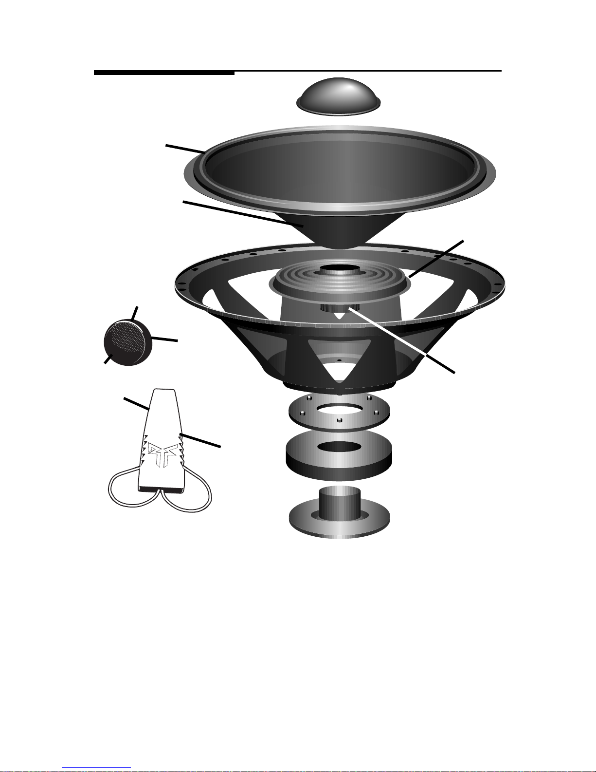
Midrange
4. Foam Surround – The specially treated foam surround withstands the
extremes of the automotive environment and “decouples” the cone from
the basket and the mounting surface for superior sound quality.
5. Mica Filled Polypropylene Cone – The ideal cone material would be
infinitely strong, very light and would have very high damping to ensure
great sound quality. The Fanatic P Series Component Systems use a
mica filled polypropylene cone that is strong, light and has high internal
damping to provide excellent reproduction of sound.
6. Cupped Spider – The spider has the job of centering the voice coil and
providing the rear suspension for the speaker. The Fanatic P Component
Systems use a durable cupped spider to ensure great sound with long
life and durability.
7. Large 1" Voice Coil with Anodized Aluminum Former – Just like all
Rockford Fosgate woofers, all Fanatic Component System midrange
drivers use an aluminum voice coil former for more efficient dissipation
of heat. Dissipating the heat is key to long life and high power handling,
so go ahead and crank it up!
Crossover
8. Butterworth Crossover – Features an 18dB per octave high-pass
crossover for the tweeter. The steeper slope of the tweeter crossover
gives better power handling.
9. Optical Compression – This built-in protection circuit limits power to the
tweeter when the “danger” threshold is exceeded. Because it simply
limits power and doesn't shut the tweeter off, this circuit is completely
inaudible.
– 3 –
Page 7

I
NSTALLATION
C
ONSIDERATIONS
Tools Needed
The following is a list of some of the tools necessary for the installation of your
speakers.
Power Drill with assorted bits #2 Phillips Screwdriver
Tape Measure Voltmeter
General
1. For safety, disconnect the negative lead from the battery prior to beginning
the installation.
2. Never run wires underneath the vehicle. Running the wires inside the vehicle
provides the best protection.
3. Avoid running wires over or through sharp edges. Use rubber or plastic
grommets to protect any wires routed through metal.
4. Mount the speakers/crossovers away from electrical sources (other than the
amplifier), i.e., power cables, electronic fuel pumps, vehicle computers,
and other potential noise sources.
5. Mount the speakers/crossovers away from areas of extreme heat or
moisture.
Speakers
1. Make sure there is an area large enough for the speaker to mount. Warning!
Failure to do this can cause damage to the speaker if the speaker frame
is bent during installation.
2. Check to see that the location is deep enough for the speaker(s) and the
location does not interfere with the normal operation of the vehicle.
3. When mounting the speaker(s) in the door of a vehicle, make sure the
speaker(s) do not interfere with either the door or window operation.
4. When mounting the speaker(s) on the rear deck of the vehicle, check the
operation of the rear hatch or trunk lid. Make sure the torsion bars and other
moving parts are not obstructed by the speaker(s) installation.
• Please refer to the Specifications section of this manual for proper mounting
diameter and depth of the speaker(s).
Crossovers
1. Make sure there is a flat area large enough for the crossover to mount.
2. For best results, mount the crossover(s) next to the amplifier for a decorative
finish to the installation and to provide an easy upgrade (no new wires to
run) for a bi-amp Rockford Fosgate system in the future.
– 4 –
Page 8

M
OUNTING
L
OCATION
A solid front stage with a good image is one of the most difficult tasks to achieve
in a vehicle. No car has the optimum listening environment. This makes proper
sound staging very difficult to accomplish. Most speakers tend to be placed
where they will fit easily, as opposed to where they can perform the best.
The
mounting location of your speakers will have a great effect on the sound quality
of your stereo system. The special care taken to place the speakers will yield
many hours of listening enjoyment in return. Several important recommendations should be followed.
• Place the speakers where they have a direct
path to the listening area.
• For the best integration between the midrange
and tweeter, the tweeter should be placed
less than 2" from the midrange. (Figure 1)
• If you cannot place the tweeter less than 2"
from the midrange, then place the tweeter
more than 7" from the midrange. Placing
the tweeter 2"-7" from the midrange can
cause destructive interference (frequency
response problems) which will affect the
speaker's ability to reproduce the frequency range around the crossover
frequency of the system.
• Whenever possible, place the tweeter directly above or below the midrange
as this maximizes the imaging (point source) capability of the speakers.
(Figure 2)
Figure 1
2" or less
Figure 2-A
Figure 2-B
– 5 –
Page 9

• Sound radiated from a “point source” has the most optimum stereo imaging
because the separation of the acoustical centers between the midrange and
tweeter for each channel is at the optimum. Figure 2-A describes a
horizontal speaker alignment. In a closed environment such as an
automobile, horizontal speaker alignment can cause severe amplitude and
phase differences which will degrade not only the imaging, but also the
frequency response. This is due to the path length differences between the
midrange and tweeter. Figure 2-B displays a vertical alignment between the
midrange and tweeter. With a vertical alignment, the path length difference
between the midrange and tweeter are reduced to a minimum. The result
is a negligible difference in path lengths between the midrange and tweeter
regardless of the proximity of the listener to the speakers. Mounting the
speaker with minimum path length difference will ensure the best staging
and imaging possible from your audio system.
I
NSTALLATION
Mounting the Midrange
– 6 –
I
N
S
T
A
L
L
A
T
I
O
N
® ®
1. Cut the proper size hole for the midrange/woofer.
• For the FNP-1404, cut an 90.48mm (39⁄16") diameter hole
• For the FNP-1405, cut a 113.50mm (415⁄32") diameter hole
• For the FNP-1406F, cut a 127mm (5") diameter hole
• For the FNP-1406, cut a 139.06mm (51⁄2") diameter hole
2. Place the mounting ring over the mounting hole and mark the location of
the screw mounting holes.
3. Remove the ring. Drill the holes for the screws using a 1/8" drill bit.
4. Route the wire through the hole.
5. Attach the wires and be sure to observe the proper speaker polarity.
6. Place the speaker into the hole and screw the speaker into place. Be
careful not to bend the speaker frame during this step.
7. Press the speaker grille into the mounting ring.
Page 10

– 7 –
Flush Mount Tweeter
Tweeter
Surface Mount Tweeter
I
N
S
T
A
L
L
A
T
I
O
N
® ®
Trim Ring
Back
Plate
Flush
Housing
Tweeter
Trim Ring
Back
Plate
Surface
Housing
Wedge Mount Tweeter
Tweeter
Wedge
Housing
Page 11

Crossover Connections
• Be Sure to Maintain Speaker Polarity
– 8 –
Negative (Black Wire)
Positive (Black/White Stripe Wire)
Midrange Negative
Tweeter Negative
Tweeter Positive
Midrange Positive
(One channel of amplifier)
+
(Purple Dot)
–
+
–
+
–
High-passing the Midrange
I
N
S
T
A
L
L
A
T
I
O
N
® ®
• The Fanatic Component Systems are optimized for full range music
reproduction. In cases where a subwoofer is used, the midrange can be
high-passed in order to prevent overlapping frequencies from the
midrange into the subwoofer.
1.Determine the frequency range that the subwoofer will play (i.e.: 20Hz80Hz)
2.Use the low-pass crossover frequency of the subwoofer system (i.e.:
80Hz) as the high-pass crossover frequency for the midrange
3.Select the appropriate capacitor value (i.e.: 500µF) to properly high-pass
the midrange
4.Place the capacitor in series with the “+” terminal of the speaker
Frequency Speaker
Hertz (4 ohms)
C1
80Hz 500µF
100Hz 400µF
130Hz 300µF
200Hz 200µF
260Hz 150µF
400Hz 100µF
Midrange Negative
Midrange Positive
+
–
C1
0dB
–3dB
80Hz
Subwoofer Midrange Tweeter
6dB/octave High-Pass
Page 12

T
ROUBLESHOOTING
No sound from
speakers
Symptom Diagnosis Remedy
Check and repair or replace
wiring as needed.
Check system with known
working amplifier and repair
or replace as needed.
Check for shorts in the wiring
with a volt/ohm meter and repair or replace wires as needed.
Check system with known working speaker and repair or replace as needed.
Wires between amplifier,
crossover or speakers not
connected properly.
Amplifier has no output.
Speaker wires are shorted
to each other or to the chassis of the vehicle.
Speakers are blown.
Incorrect wiring between
crossover and speakers
Excessive power from amplifier
Equalizer in system (if
available) has excessive
boost in the high frequency
range
Check wiring and repair or replace as needed.
Check gain settings on amplifier and readjust as necessary
Check settings on equalizer and
readjust as necessary
Distorted sound
from speakers
Tweeters “burn
up” easily
– 9 –
Engine Noise from
One or More
Speakers
Check for shorts in the wiring
with a volt/ohm meter and repair or replace wires as needed.
Re-route speaker wiring away
from noise sources. (Refer to
the Installation Consider-
ations section of this manual.)
Move crossovers away from
noise sources. (Refer to the In-
stallation Considerations section of this manual.)
Speaker wires shorted to
chassis of vehicle.
Speaker wires are routed
near radiated noise source.
(Power cables, vehicle
computers, etc.)
Crossover is mounted near
radiated noise source.
(Power cables, vehicle
computers, etc.)
Page 13

System Model Number FNP1414 FNP1514 FNP1614F FNP1614
Midrange Model Number FNP1404 FNP1405 FNP1406F FNP1406
Nominal Diameter 4" 5
1
⁄4"6"6
1
⁄2"
Nominal Impedance 4Ω 4Ω 4Ω 4Ω
Frequency Response 100Hz-8kHz 60Hz-6kHz 61Hz-6kHz 55Hz-5kHz
Fs (Hz) 100Hz 60Hz 61Hz 55Hz
Qes .907 .705 .701 .926
Qms 3.372 2.896 2.58 3.558
Qts .715 .567 .551 .733
Vas (ft3/liter) .078/2.2 .29/8.1 .335/9.5 .59/16.7
Xmax (in/mm) .09/2.4 .11/2.9 .11/2.9 .11/2.9
Sensitivity 84.9dB 86.4dB 86.8dB 87.1dB
RMS Power Handling 50 Watts 50 Watts 50 Watts 50 Watts
Mounting Diameter 90.48mm 113.50mm 127mm 139.06mm
(39⁄16") (415⁄32") (5") (51⁄2")
Mounting Depth 48mm (1
29
⁄32") 60mm (23⁄8") 61mm (213⁄32") 63mm (21⁄2")
S
PECIFICATIONS
(Specifications are subject to change without notice)
– 10 –
Wedge
Mount
Surface
Mount
Flush
Mount
* Power Ratings (PE) is established with recommended filter network.
1.75"
.875"
3.687"
4.437"
1.74"
1.00"
1.94"
.375"
1.00"
.25"
1.795"
.965"
.675"
1.562"
1.24"
Model FNP142x
Crossover Type 2-Way
Crossover Frequency 6.3kHz @ 4Ω
Crossover Slope 18dB/octave High-Pass
Full Range Low-Pass
Filter Q 0.707 (Butterworth)
Tweeter Protection Optical Compression
Dimensions See drawings
Model FNP1401
Nominal Diameter 3/4" (20mm)
Nominal Impedance 4Ω
Frequency Response 2.8kHz-20kHz
Fs 2.8kHz
Sensitivity 91dB
RMS Power Handling 50 Watts*
Mounting Diameter See drawings
Mounting Depth See drawings
Page 14

– 11 –
L
IMITED
W
ARRANTY
I
NFORMATION
Rockford Corporation offers a limited warranty on Rockford Fosgate products on the following
terms:
• Length of Warranty
1 year on speakers 30 days on speaker B-stock (receipt required)
3 years on electronics 90 days on electronic B-stock (receipt required)
2 years on source units
• What is Covered
This warranty applies only to Rockford Fosgate products sold to consumers by Authorized
Rockford Fosgate Dealers in the United States of America or its possessions. Product
purchased by consumers from an Authorized Rockford Fosgate Dealer in another country
are covered only by that country’s Distributor and not by Rockford Corporation.
• Who is Covered
This warranty covers only the original purchaser of Rockford product purchased from an
Authorized Rockford Fosgate Dealer in the United States. In order to receive service, the
purchaser must provide Rockford with a copy of the receipt stating the customer name,
dealer name, product purchased and date of purchase.
• Products found to be defective during the warranty period will be repaired or replaced
(with a product deemed to be equivalent) at Rockford's discretion.
• What is Not Covered
1. Damage caused by accident, abuse, improper operations, water, theft
2. Any cost or expense related to the removal or reinstallation of product
3. Service performed by anyone other than Rockford or an Authorized Rockford Fosgate
Service Center
4. Any product which has had the serial number defaced, altered, or removed
5. Subsequent damage to other components
6. Any product purchased outside the U.S.
7. Any product not purchased from an Authorized Rockford Fosgate Dealer
• Limit on Implied Warranties
Any implied warranties including warranties of fitness for use and merchantability are
limited in duration to the period of the express warranty set forth above. Some states do not
allow limitations on the length of an implied warranty, so this limitation may not apply. No
person is authorized to assume for Rockford Fosgate any other liability in connection with
the sale of the product.
• How to Obtain Service
Please call 1-800-669-9899 for Rockford Customer Service. You must obtain an RA#
(Return Authorization number) to return any product to Rockford Fosgate. You are
responsible for shipment of product to Rockford.
Ship to: Electronics
Rockford Corporation
Warranty Repair Department
2055 E. 5th Street
Tempe, AZ 85281
RA#:_________________
Ship to: Speakers
Rockford Acoustic Design
(Receiving-speakers)
609 Myrtle N.W.
Grand Rapids, MI 49504
RA#:_________________
Page 15

INTERNATIONAL
INFORMATION
– 12 –
Page 16

2/98
LIT9943
Rockford Fosgate
Rockford Corporation
546 South Rockford Drive
Tempe, Arizona 85281 U.S.A.
In U.S.A., (602) 967-3565
In Europe, Fax (49) 8503-934014
In Japan, Fax (81) 559-79-1265
MADE IN THE USA
This product is designed, developed and assembled in the USA by a dedicated
group of American workers. The majority of the components used in the
construction of this product are produced by American companies. However,
due to the global nature of their manufacturing facilities and the loudspeaker
parts industry in general, some parts may be manufactured in other countries.
 Loading...