

Rockford Fosgate 250 sERIES, 250X2, 250m Installation & Operation Manual

®®

INTRODUCTION
The “250 Series” Power amplifiers represent the best Rockford Fosgate has to offer! Our
engineers devised technical features which would be considered overkill by other audio
manufacturers, but not at Rockford Fosgate! Trans•nova, DIABLO, and TOPAZ, exclusively
designed by Rockford, are just a few of these features which are described in the Technical
Design Features section of this manual.
The 250x2 is a two-channel amplifier which is optimized to drive 2Ω stereo and 4Ω bridged
loads. The 250m is a single channel amplifier optimized to drive a 2Ω (single amp) or a 4Ω
bridged load (pair of amps bridged to a single load.)
The 250x2 and 250m utilize Rockford's innovative technologies for awesome sound quality,
reliable performance ad tremendous amounts of output power. The “250 Series” represent
exactly what Rockford Fosgate designs: Car Audio for Fanatics!

Dear Customer,
Congratulations on your purchase of the world's finest brand of car audio amplifiers. At Rockford Fosgate we
are fanatics about musical reproduction at its best, and we are pleased you chose our product. Through years
of engineering expertise, hand craftsmanship and critical testing procedures, we have created a wide range of
products that reproduce music with all the clarity and richness you deserve.
For maximum performance we recommend you have your new Rockford Fosgate product installed by an
Authorized Rockford Fosgate Dealer, as we provide specialized training through Rockford Technical Training
Institute (RTTI). Please read your warranty and retain your receipt and original carton for possible future use.
Great product and competent installations are only a piece of the puzzle when it comes to your system. Make
sure that your installer is using 100% authentic installation accessories from Connecting Punch in your
installation. Connecting Punch has everything from RCA cables and speaker wire to Power line and battery
connectors. Insist on it! After all, your new system deserves nothing but the best.
To add the finishing touch to your new fanatic image order your Rockford Fosgate wearables, which include
everything from T-shirts and jackets to hats and sunglasses.
To get a free brochure on Rockford Fosgate products and Rockford wearables, please call 602-967-3565 or FAX
602-967-8132. For International orders, FAX +001-1-602-967-8132 or call +001-1-602-967-3565.
PRACTICE SAFE SOUND™
CONTINUOUS EXPOSURE TO SOUND PRESSURE LEVELS OVER 100dB MAY CAUSE PERMANENT
HEARING
WELL
If, after reading your manual, you still have questions regarding this product, we recommend that you see your
Rockford Fosgate dealer. If you need further assistance, you can call us direct at 1-800-795-2385. Be sure to have
your serial number, model number and date of purchase available when you call.
The serial number can be found on the outside of the box. Please record it in the space provided below as your
permanent record. This will serve as verification of your factory warranty and may become useful in recovering
your amplifier if it is ever stolen.
LOSS. HIGH POWERED AUTOSOUND SYSTEMS MAY PRODUCE SOUND PRESSURE LEVELS
OVER 130dB. USE COMMON SENSE AND PRACTICE SAFE SOUND.
Serial Number: __________________________________________
Model Number:__________________________________________

TABLE OF CONTENTS
Introduction ..............................................................................................................................................................1
Punch Accessory Pack ..............................................................................................................................................1
Technical Design Features ........................................................................................................................................2
250x2 Design Features ..............................................................................................................................................5
250m Design Features...............................................................................................................................................7
Installation Considerations ........................................................................................................................................9
Mounting Locations ................................................................................................................................................10
Battery and Charging...............................................................................................................................................10
Wiring the System ...................................................................................................................................................11
Using the XCard......................................................................................................................................................13
Customizing the XCard ...........................................................................................................................................13
XCard Resistor Chart ...............................................................................................................................................14
250x2 Installation....................................................................................................................................................15
Using the 250x2 Internal Switching Network...........................................................................................................18
Using the 250x2 Balanced Line Inputs.....................................................................................................................23
250m Installation ....................................................................................................................................................25
Using the 250m Internal Switching Network ...........................................................................................................30
System Diagrams.....................................................................................................................................................33
Rockford Fosgate Accessories..................................................................................................................................37
Troubleshooting ......................................................................................................................................................42
Autosound 2000’s Quick Check for Troubleshooting ..............................................................................................45
250x
Specifications................................................................................................................................................47
2
250m Specifications................................................................................................................................................48
Warranty Information..............................................................................................................................................49
International Information.........................................................................................................................................50
GETTING STARTED
Welcome to Rockford Fosgate! This manual is designed to provide information for the owner, salesperson and
installer. For those of you who want quick information on how to install this product please turn to the
section of this manual or refer to the icons listed below. Other information can be located by using the Table of
Contents. We, at Rockford Fosgate, have worked very hard to make sure all the information in this manual is
current. But, as we are constantly finding new ways to improve our product, this information is subject to change
without notice.
a
O
▲
p
d
e
v
r
a
a
n
t
c
i
e
o
d
n
Sections marked
ADVANCED
OPERATION
include in-depth
technical information
I
® ®
N
S
T
A
L
L
A
T
I
O
N
Sections marked
INSTALLATION
include “slam dunk”
wiring connections
Installation
TROUBLE-
Sections marked
TROUBLESHOOTING
include recommendations
for curing installation
problems
S
H
O
O
T
I
N
G

Our Dream
nova
The “250 Series” Power amplifiers represent the best Rock-
ford Fosgate has to offer! Our engineers devised technical
features which would be considered overkill by other audio
manufacturers, but not at Rockford Fosgate! Trans•
DIABLO and TOPAZ, exclusively designed by Rockford, are
just a few of these features which are described in the
Technical Design Features section of this manual.
is a two-channel amplifier
2
250x
The
drive 2Ω stereo and 4Ω bridged loads. The
channel amplifier
4Ω bridged load (pair of amps bridged to a single load).
The 250x
nologies for awesome sound quality, reliable performance
and tremendous amounts of output power. The “250 Series”
represent exactly what Rockford Fosgate designs:
for Fanatics!
optimized to drive a 2Ω (single amp) or a
and 250m utilize Rockford's innovative tech-
2
which is optimized to
250m is a single
,
Car Audio
PUNCH AMPLIFIER ACCESSORY PACK
The accessory pack shipped with the “250 series” Power amplifiers include the mounting hardware necessary
to secure it to the vehicle as well as attaching the end caps.
Installation & Operation Manual
Punch Verification Certificate
(8) Allen Head screws for speaker and power connectors (250x2)
(6) Allen Head screws for speaker and power connectors (250m)
(4) Mounting screws for end caps
(4) Mounting screws for amplifier
(1) Allen wrench 7/64"
(1) Allen wrench 3/32"
– 1 –
TECHNICAL DESIGN FEATURES
Many of the solutions to common design problems encountered by Rockford Fosgate engineers created entire
new circuit designs as well as new ways to construct the Punch 250x
amplifiers, no expense was spared in design and construction from the unique circuitry design to the
manufacturing process that has proven to be the industry reference for many years. Described below are just some
of the accomplishments achieved by our engineering and manufacturing staff.
and 250m Power Amplifiers. In our flagship
2
◆ trans•
The trans•
allows the audio signal to pass through the amplifier at
floating” power supply and is configured to increase power gain. The increase in power gain allows the drive
stage to operate at a lower voltage. A low voltage drive stage is the same principle used in high quality
preamplifiers to produce high linearity and wide bandwidth.
The resulting design utilizes an output stage with a simpler gain structure and a shorter total signal path than
conventional high voltage (bi-polar) designs. The number of stages is reduced from five or more to three. The
output stage is further refined into a trans-impedance stage (current to voltage converter) to achieve a short loop
(fast) negative feedback. The output stage is driven cooperatively by a transconductance stage (voltage to current
converter).
THE RESULT: Superior sound quality, greater efficiency and higher reliability.
nova
nova
(TRANS conductance NOdal Voltage Amplifier) is a patented circuit (U.S. Patent 4,467,288) that
E-I I-E
(TRANSconductance NOdal Voltage Amplifier)
low voltage
trans•nova circuitry
. Each amplifier channel utilizes its own “fully
◆ DIABLO (Dynamically Invariant A-B Linear Operation)
DIABLO
in circuit design which reduces high frequency distortion. Amplifiers which utilize a large array of output
MOSFETs cause a high capacitive load on the driver stage. This load can make the high frequencies sound harsh.
The DIABLO circuit eliminates high frequency distortion by allowing the driver to operate with 20dB or more
of current headroom, whereas traditional drives have only 6dB of current headroom.
THE RESULT: Lower distortion and greater inherent stability.
(Dynamically Invariant A-B Linear Operation - patent application in process) is an important advance
◆ TOPAZ (Tracking Operation Pre-Amplifier Zone)
The
TOPAZ
automotive amplifier design. This innovative new development allows vastly improved isolation of the input
signal grounds from the power supply ground of the amplifier. This is accomplished by allowing the source unit
to control the potential “environment” of the entire input structure or “zone” of the amplifier. This process
improves the noise rejection of the amplifier by 30-40dB – an astounding 20-100 times better than amplifiers
without TOPAZ.
THE RESULT: Elimination of troublesome ground loop noise between source and amplifier.
(Tracking Operation Pre-Amplifier Zone) circuitry solves ground loop noise problems common to
– 2 –
◆ DSM (Discrete Surface Mount Technology)
The
DSM
(Discrete Surface Mount) manufacturing process combines the advantages of both discrete components
and integrated circuitry. Rockford Fosgate is the only American amplifier manufacturer to have invested millions
into this process. DSM components differ from conventional discrete components in different ways. They are
more compact, more rugged, and they efficiently dissipate generated heat. Using them wherever appropriate
allows the advantages associated with discrete circuitry to be retained while also providing room for both highly
advanced processing features and generous PC board copper paths where needed. Their short lead-out structures
allow maximum audio performance and highest signal-to-noise ratios to be obtained in amplifiers of desirable
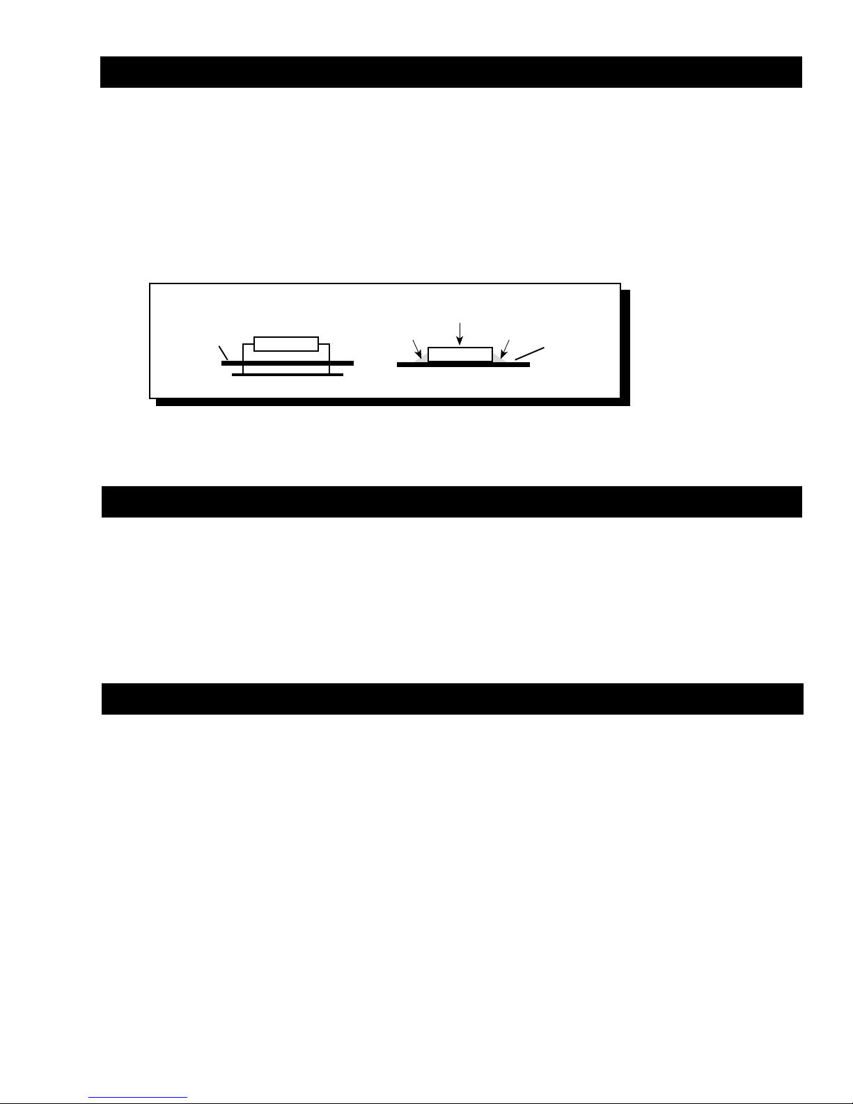
package size without resorting to “amplifier-on-a-chip” shortcuts. These advantages are shown below in Figure 1.
Solder
Component
Solder
PC Board
Figure 1
PC Board
Thru-Hole Surface Mount
THE RESULT: Less connections, improved reliability, shorter signal paths, superior signal-to-noise ratio and
awesome sonic performance.
◆ XCard (Internal Crossover)
The Power amplifiers utilize internal active crossovers. These crossovers have many performance advantages
such as using discrete components for exact frequency adjustments which are far superior to potentiometers.
Additionally, the
modification, many crossover frequencies and slope configurations can be achieved.
THE RESULT: Increased system design flexibility with a precise electronic crossover without the limitations of
conventional potentiometer designs.
XCard
can be configured for high-pass, low-pass and full range operation. With slight
◆ Stereo Pass-Thru
The
Pass-Thru
for extra RCA cables or “Y” adapters. The 250m Pass-Thru provides constant Full Range stereo output. The 250x
has the ability to provide constant Full Range stereo output as well as distribute one of its internal XCards to the
Pass-Thru for a dedicated High-Pass or Low-Pass output.
THE RESULT: Convenient signal level output for adding extra amplifiers.
output provides a convenient source for daisy-chaining an additional amplifier without the need
2
– 3 –

◆ Balanced Line Inputs (250x2)
Using the 250x2 with the
BLT
(Balanced Line Transmitter)
provides the last word in achievable rejection of noise
induced in the cable between the source and the amplifier.
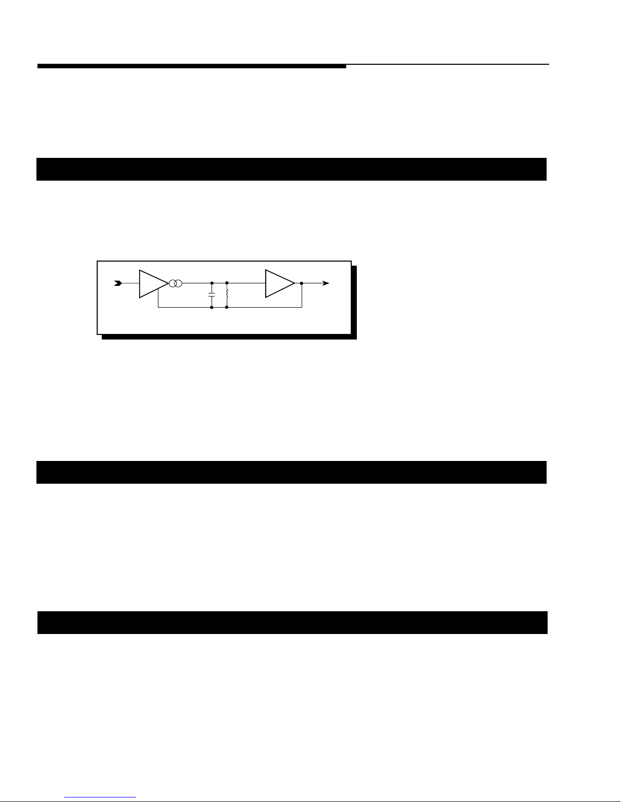
The differential input circuitry (Figure 2) used in the balanced input system rejects whatever signals are common
to both of the shielded, twisted-pair conductors. Balanced
line is universal in concert installations where the stage and
Figure 2
Center
Conductor
Outer
Shield
Differential inputs only amplify the difference between two conductors. Note: the noise spikes appear on both the center conductor and the outer shield and therefore are not amplified.
RCA Input
Differential
Input
mixing consoles are hundreds of feet apart. Long signal
cables and electrically-noisy environments make signal
integrity and noise rejection an extremely difficult challenge.
THE RESULT: Quiet transmission of audio from source to amplifier.
◆ NOMAD (NOn-Multiplying Advanced Decision)
The Power amplifiers use an
operating conditions. The innovative
sophisticated version of this technique ever used, bringing previously unavailable levels of accuracy, stability,
temperature immunity and reliability to this critical process. NOMAD makes advanced decisions based on
device voltages to precisely control the awesome levels of current available in the output MOSFETs to safe values
– but only when absolutely needed.
analog computer process
NOMAD
(NOn-Multiplying Advanced Decision) system is the most
to absolutely maximize safe output power under all
THE RESULT: Extremely fast protection system that always protects the amplifier and never degrades the sound.
◆ MOSFET Devices (Metal Oxide Semiconductor Field Effect Transistor)
Rockford Fosgate is one of the few manufacturers in any of the sound communities to utilize MOSFET devices
in both the
power supply
and the
output stages. MOSFET
(Metal Oxide Semiconductor Field Effect Transistor)
devices offer several important inherent advantages over the 30 year old technology of bi-polar design. These
advantages include: thermal stability, switching speed, ultra low output impedance and wider bandwidth
linearity. In addition, MOSFET and vacuum tubes share many important operating characteristics. However, the
MOSFET device is much faster, wider in bandwidth, measurably lower in distortion and far more linear than
vacuum tubes.
THE RESULT: Operational characteristics of vacuum tubes without the performance limitations of tube design.
◆ ITS (Increased Thermal Stability)
The
ITS
(Increased Thermal Stability) Power Supply design is new in Rockford Fosgate amplifiers. A major
problem associated with any amplifier design is how to get rid of the heat generated by its circuitry. Clearly, it
is highly desirable to minimize the amount of heat generated in the first place. The “250 series” Power amplifiers
employ a new toroidal power transformer design in which the high current input leads are carried directly to the
switching power MOSFETs. This both minimizes PC board heating and takes advantage of natural air cooling of
these leads.
THE RESULT: Maximizes power supply efficiency by eliminating unnecessary heat generation.
– 4 –
250X2 DESIGN FEATURES
1. Cast Aluminum Heatsink – The cast aluminum heatsink of the Punch Power amplifier dissipates heat
generated by the amplifier's circuitry. The inherent advantage of casting provides a 30% improvement of
cooling over conventional extrusion heatsink designs.
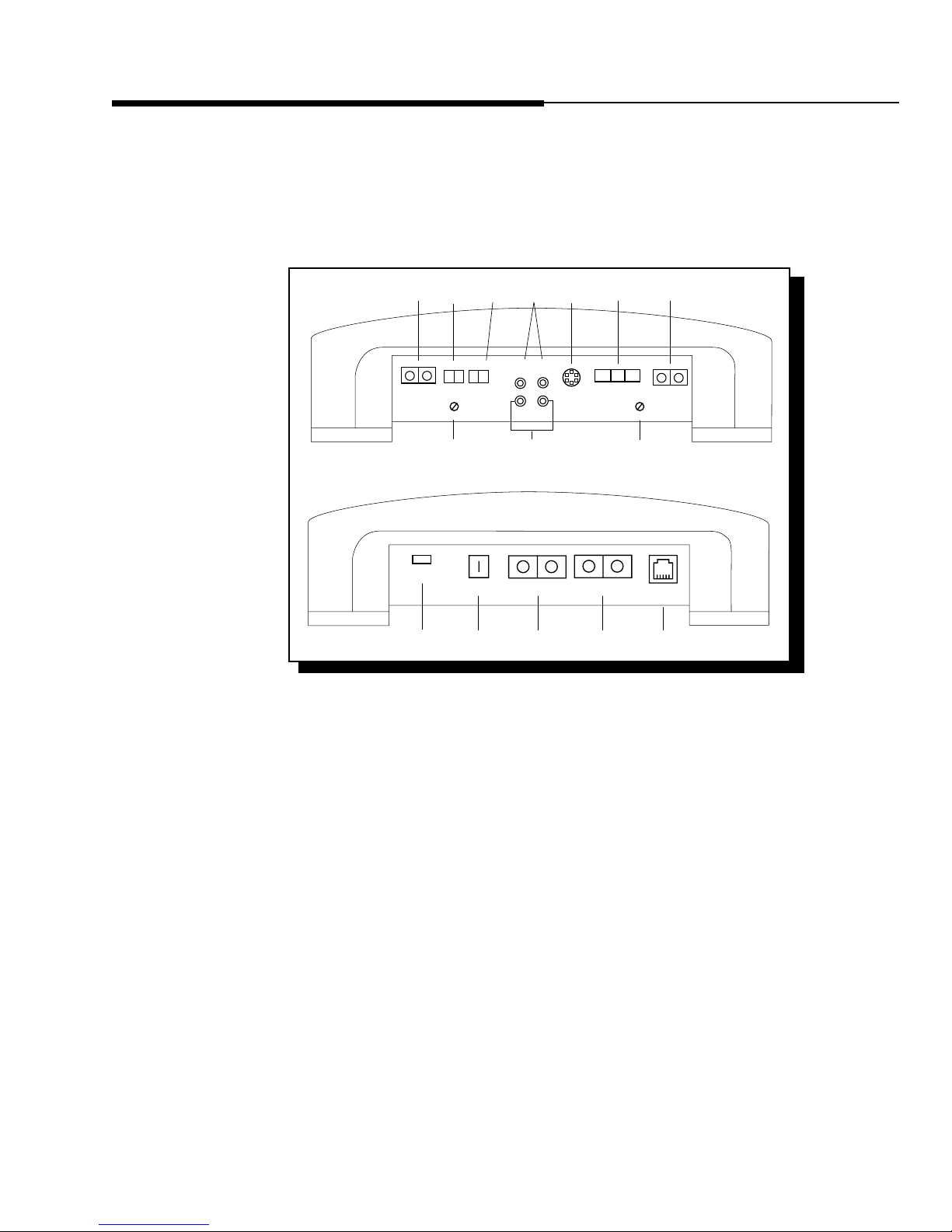
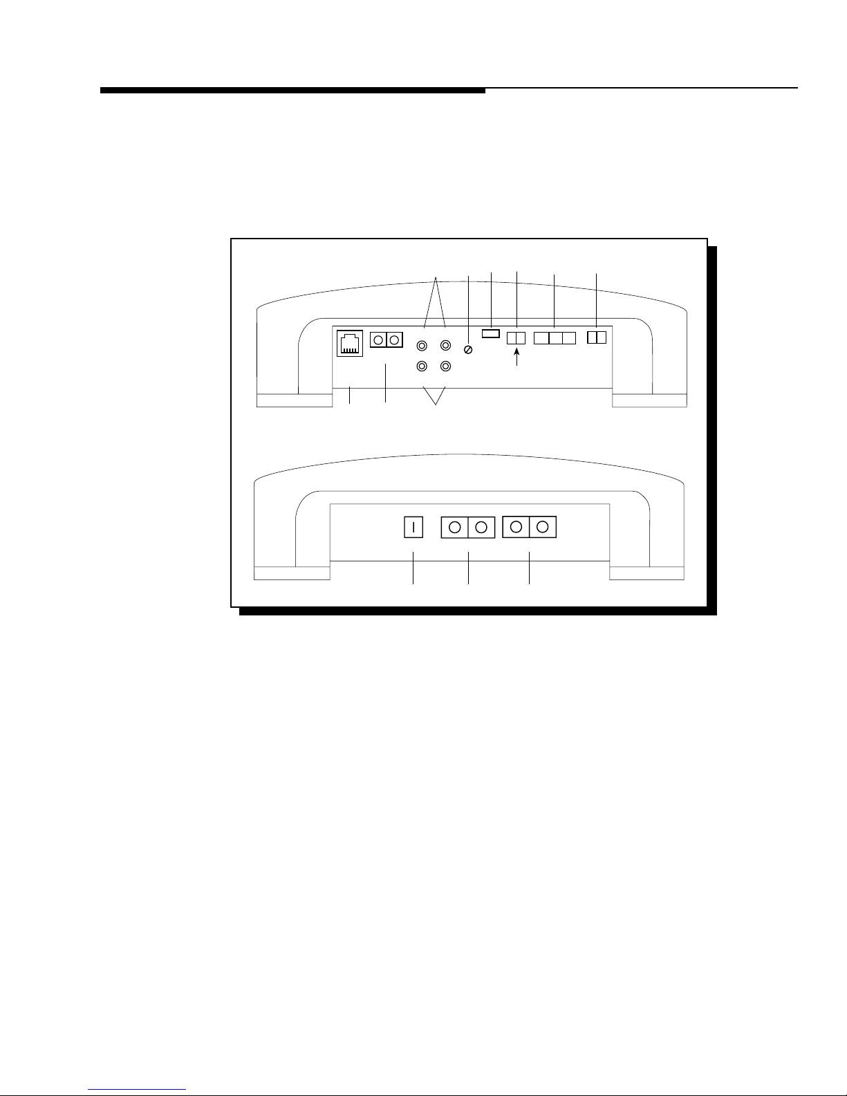
2. End Caps – Interchangeable end caps conceal the wiring and input cables, giving the amplifier a clean
“stealth” look.
3 13 8
Unbal.
Speaker
+ L –
0°-180
°
10
Power
Bal.
REM Dual GNDDual B+
Pass
Thru
L (Mono)
L
697
R
R
Bal.
Input
EZ-180°-0
Bridged
°
Speaker
– R +
GainGain
10
Punch Status
Display
312
16 5 4 4 17
3. Speaker Terminals – The heavy duty, gold-plated terminal block connectors (+ and –) will accept wire
sizes from 8 AWG to 18 AWG. These gold-plated connectors are immune to corrosion that can cause signal
deterioration.
4. Power Terminals – The dual power and ground connectors on the Punch Power amplifier are gold-plated
and will accommodate up to two 8 AWG wires maximizing the input current capability of the amplifier.
5. REM Terminal – This gold-plated spade terminal is used for the AP (auto power) or remote turn on of the
Punch 250x2 Power amplifier.
6. RCA Input Jacks – The industry standard RCA jack provides an easy connection for signal level input. They
are gold-plated to resist the signal degradation caused by corrosion.
7. Balanced Line Input– This input will allow the balanced inputs to be used in conjunction with the Punch
250x2 Power amplifier to provide better noise rejection.
8. Signal Input Switch – This switch allows selection of either the RCA or Balanced Line inputs.
9. RCA Pass-Thru Jacks – The Pass-Thru provides a convenient source for daisychaining an additional
amplifier. This eliminates the need for additional RCA cables or “Y” adapters. One of the internal
crossovers can be designated to the Pass Thru output creating a dedicated low-pass, high-pass, or full range
output.
– 5 –
10. Input Sensitivity Controls – The input level controls are preset for 500mV which will match the output
Low-Pass Full RangeHigh-Pass
ROCKFORD CORPORATION
M
ADE IN THE USA
®
®
AMPLIFIER
XCard 1
XCard 2
Audiophile Bypass
Not Used
XCard 1
XCard 2
Pass Thru
XCard Options
XCard 1
XCard 2
11
14 & 15
XCard 1
XCard 2
Amplifier
XCard 1
XCard 2
XCard Options
Not Used
Audiophile Bypass
Not Used
Amp Only
Pass Thru
Amplifier
Amplifier
HP
➝
➝
LP
HP
➝
➝
LP
FULL
↕
PO
W
ER
250
®
*Bridging Note: The Punch 250x
2
can be
bridged in many configurations. Refer to your
owner's manual to determine which mode will
work best in your system.
125 Watts X 2 into 4 Ohms
with less than 0.05% THD + N from 20-20kHz
225 Watts X 2 into 2 Ohms
with less than 0.10% THD + N from 20-20kHz
of most source units. They can be adjusted to match input levels ranging from 300mV to 5V.
11. Internal Crossovers – These built-in crossover cards are configurable for a multitude of operating
frequencies. The orientation of the card in its socket determines its function of high-pass, low-pass or full
range operation.
12. E-Z Bridge Switch / 0
°-180° Phase Switch – This dual purpose switch enables you to E-Z bridge the
amplifier or invert the signal phase of the right channel.
13. Phase Switch – This switch enables you to easily invert the phase of the left channel without having to
disconnect the speaker wires.
14. Crossover Switching – These internal switches allow the crossover to be distributed to the amplifier and
Pass-Thru in many different configurations.
15. Audiophile Bypass – One of the crossover switching configurations allows the internal crossover circuit
to be bypassed, maintaining Audiophile sound quality due to a shorter signal path.
16. LED Power Indicator – The LED gives a visual indication of the status of the amplifier, lighting when the
unit is turned on.
17. Punch Status Display – The RJ11 interface allows connection of an LED display used to monitor amplifier
performance.
– 6 –
250m DESIGN FEATURES
1. Cast Aluminum Heatsink – The cast aluminum heatsink of the Punch Power amplifier dissipates heat
generated by the amplifier's circuitry. The inherent advantage of casting provides a 30% improvement of
cooling over conventional extrusion heatsink designs.
2. End Caps – Interchangeable end caps conceal the wiring and input cables, giving the amplifier a clean
“stealth” look.
Punch
Status
Display
14
6
Speaker
– +
R Pass ThruL Pass Thru
3
8
REM Dual GNDDual B+
5 4 4
9 7
RL (Mono)
Gain
13 1112
Power
24dB/12dB/0dB
L + R / L
(Mono)
X-Over
0°–180°
3. Speaker Terminals – The heavy duty, gold-plated terminal block connectors (+ and –) will accept wire
sizes from 8 AWG to 18 AWG. These gold-plated connectors are immune to corrosion that can cause signal
deterioration.
4. Power Terminals – The dual power and ground connectors on the Punch Power amplifier are gold-plated
and will accommodate up to two 8 AWG wires maximizing the input current capability of the amplifier.
5. REM Terminal – This gold-plated spade terminal is used for the AP (auto power) or remote turn on of the
Punch 250m Power amplifier.
6. RCA Input Jacks – The industry standard RCA jack provides an easy connection for signal level input. They
are gold-plated to resist the signal degradation caused by corrosion.
7. Summed Stereo / Mono Switch – This switch is used to select whether 1 or 2 signal inputs will be used
to drive the amplifier.
8. Pass-Thru RCA Jacks – The Pass-Thru provides a convenient source for daisychaining an additional
amplifier.This eliminates the need for additional RCA cables or “Y” adapters. The Pass-Thru output is Full
Range only.
9. Input Sensitivity Control – The input level control is preset for 500mV which will match the output of most
source units. It can be adjusted to match input levels ranging from 300mV to 5V.
– 7 –
10. Internal Crossover – This built-in crossover card is configurable for a multitude of operating frequencies.
Low Pass Full RangeHigh Pass
FULL
↕
ROCKFORD CORPORATION
MADE IN THE USA
®
XCard 1
10
+
–
Do Not Chassis
Ground Any
Speaker Wire.
+ –
HP
➝
➝
LP
HP
➝
➝
LP
250 Watts X 1 into 4 Ohms
with less than 0.10% THD + N from 20-20kHz
500 Watts X 1 into 2 Ohms
with less than 0.15% THD + N from 20-20kHz
®
250
POWER
®
AMPLIFIER
The orientation of the card in its socket determines the function of high-pass, low-pass or full range
operation.
11. Phase Switch – This switch enables you to easily invert the phase without having to disconnect the
speaker wires.
12. Crossover Switch – This multi-function switch enables you to select a 12dB per octave slope or 24dB per
octave slope of the internal crossover. When switched to 0dB, the internal crossover circuit can be
bypassed, maintaining Audiophile sound quality due to a shorter signal path.
13. LED Power Indicator – The LED illuminates when the unit is turned on.
14. Punch Status Display – The RJ11 interface allows connection of an LED display used to monitor amplifier
performance.
– 8 –

INSTALLATION CONSIDERATIONS
Tools Needed
The following is a list of tools you will need for installing the Punch 250x2 and 250m Power amplifiers:
Allen wrenches 7/64" & 3/32" (included) Wire Cutters
Wire strippers Voltmeter
Battery post wrench Wire crimpers
Electric hand drill and assorted bits Assorted connectors
This section focuses on some of the vehicle considerations for installing your new Punch amplifier. Checking
your battery and present sound system, as well as pre-planning your system layout and best wiring routes will
save installation time. When deciding on the layout of your new system, be sure that each component will be
easily accessible for making adjustments.
Before beginning any installation, be sure to follow these simple rules:
1. Carefully read and understand the instructions before attempting to install the amplifier.
2. For safety, disconnect the negative lead from the battery prior to beginning the installation.
3. For easier assembly, we suggest you run all wires prior to mounting your amplifier in place.
4. Route all of the RCA cables close together and away from any high current wires.
5. Use high quality Connecting Punch accessories for a reliable installation and to minimize signal or
power loss.
6. Think before you drill! Be careful not to cut or drill into gas tanks, fuel lines, brake or hydraulic lines,
vacuum lines or electrical wiring when working on any vehicle.
7. Never run wires underneath the vehicle. Running the wires inside the vehicle provides for best
protection.
8. Avoid running wires over or through sharp edges. Use rubber or plastic grommets to protect any wires
routed through metal, especially the firewall.
9. ALWAYS protect the battery and electrical system from damage with proper fusing. Install a fuseholder
and fuse on the +12V power wire within 18" (45.7cm) of the battery terminal.
10. When grounding to the chassis of the vehicle, scrape all paint from the metal to ensure a good, clean
ground connection. Grounding connections should be as short as possible and always be connected
to metal that is welded to the main body, or chassis, of the vehicle.
– 9 –

MOUNTING LOCATIONS
The mounting location and position of your amplifier will have a great effect on its ability to dissipate the heat
generated under normal operation. The design of our cast aluminum heatsink serves to easily dissipate the heat
generated over a wide range of operating conditions. However, to maximize the performance of your amplifier,
care should be taken to ensure adequate ventilation.
Trunk Mounting
Mounting the amplifier vertically on a surface with the fin grooves running up and down will provide the best
cooling of the amplifier.
Mounting the amplifier on the floor of the trunk will work but provides less cooling capability than
vertical mounting.
Mounting the amplifier upside down to the rear deck of the trunk will not provide proper cooling and will
severely affect the performance of the amplifier and is strongly
Passenger Compartment Mounting
Mounting the amplifier in the passenger compartment will work as long as you provide a sufficient amount of
air for the amplifier to cool itself. If you are going to mount the amplifier under the seat of the vehicle, you must
have at least 1" (2.54cm) of air gap around the amplifier's heatsink.
not
recommended.
Mounting the amplifier with less than 1" (2.54cm) of air gap around the heatsink in the passenger compartment
will not provide proper cooling and will severely affect the performance of the amplifier and is strongly
not
recommended.
Engine Compartment Mounting
Rockford Fosgate amplifiers should
warranty but could create an embarrassing situation caused by the ridicule from your friends.
never
be mounted in the engine compartment. Not only will this void your
BATTERY AND CHARGING
Amplifiers will put an increased load on the vehicle's battery and charging system. We recommend checking
your alternator and battery condition to ensure that the electrical system has enough capacity to handle the
increased load of your stereo system. Stock electrical systems which are in good condition should be able to
handle the extra load of any Rockford amplifier without problems, although battery and alternator life can be
reduced slightly. To maximize the performance of your Rockford Fosgate amplifier, we suggest the use of a heavy
duty battery, high output alternator and an energy storage capacitor.
– 10 –
WIRING THE SYSTEM
CAUTION: Avoid running power wires near the low level input cables, antenna, power leads, sensitive
equipment or harnesses. The power wires carry substantial current and could induce noise into the audio system.
1. Configure the internal XCard crossovers prior to installation. Refer to the “Using the Internal Switching
Network” (page 18 for the 250x2 and page 30 for 250m) for further information.
2. Plan the wire routing. Take care when running signal level RCA cables to keep them close together but
isolated from the amplifier's power cables and any high power auto accessories, especially electric motors.
This is done to prevent coupling the noise from radiated electrical fields into the audio signal. When feeding
the wires through the firewall or any metal barrier, protect them with plastic or rubber grommets to prevent
short circuits. Leave the wires long at this point to adjust for a precise fit at a later time.
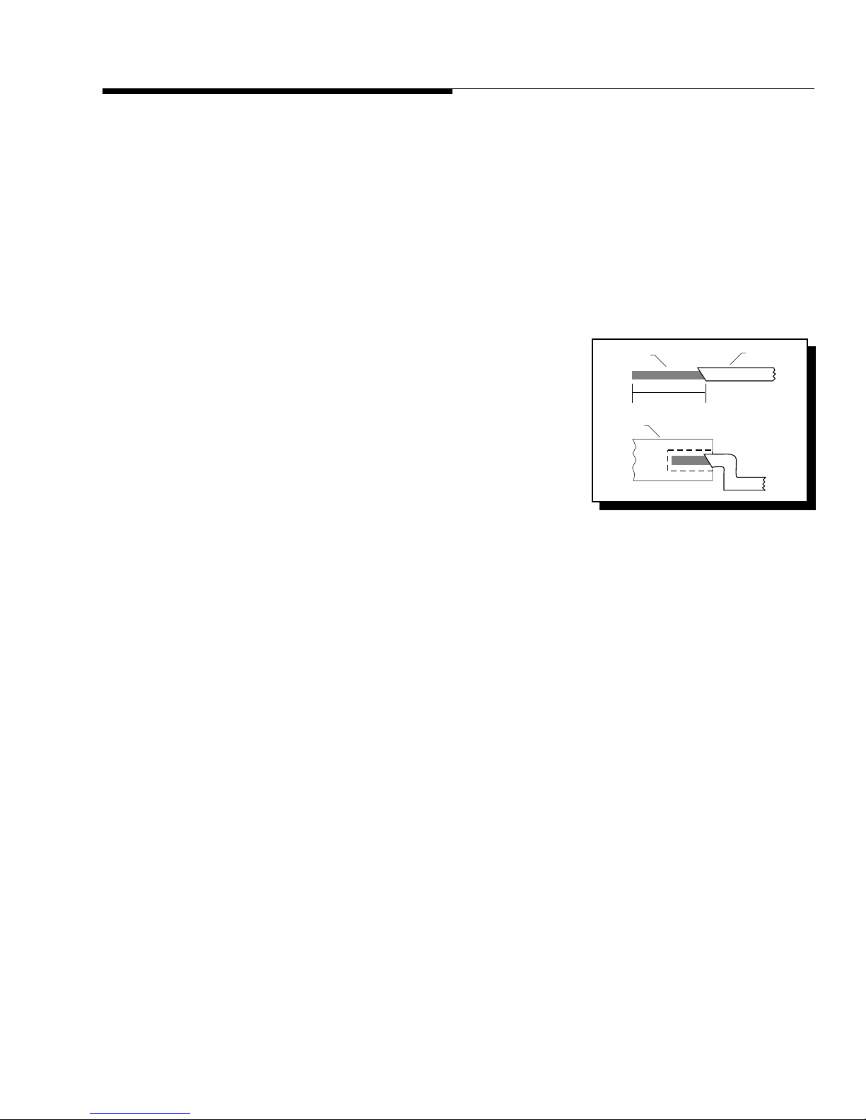
3. Prepare the Power cable for attachment to the amplifier by stripping
5/8" of insulation from the end of the wire. The use of 8 gauge power
cable can interfere with the installation of the end caps. Proper wire
dress can prevent this from occurring. To prevent the wire from
fraying, strip the insulation at a 45° angle. Insert the bared wire into
the B+ terminal with the long side of the insulation on the top. Bend
STRIP WIRE
AMP
>
><
5/8"
>
INSULATION
>
the cable down at a 90° angle. Tighten the set screw to secure the
cable in place. We recommend using (2) 8 gauge cables for power
and for ground. This will give you the best performance possible.
4. Strip 3/8" from the battery end of the power cable and crimp a large ring terminal to the cable. Use the ring
terminal to connect to the battery positive terminal. Do not install the fuse at this time.
5. Prepare a length of cable to be used for the ground connection. Strip 5/8" of insulation from the end of the
cable as described above and connect to the appropriate terminal of the amplifier. Prepare the chassis ground
by scraping any paint from the metal surface and thoroughly clean the area of all dirt and grease. Strip the
other end of the wire and attach a ring connector. Fasten the cable to the chassis using a non-anodized screw
and a star washer.
6. Prepare the REM turn-on wire for connection to the amplifier by stripping 5/8" of insulation from the wire
end and crimping an insulated spade connector in place. Slide the connector over the REM terminal on the
amplifier. Connect the other end of the REM wire to a switched 12 volt positive source. The switched signal
is usually taken from the source unit's auto antenna or the accessory lead. If the source unit does not have
these outputs available, the recommended solution is to wire a mechanical switch in line with a 12 volt
source to activate the amplifier.
7. Securely mount the amplifier (with supplied screws) to the vehicle or amp rack. Be careful not to mount the
amplifier on cardboard or plastic panels. Doing so may enable the screws to pull out from the panel due
to road vibrations or sudden vehicle stops.
8. Connect the source signal to the amplifier by plugging the RCA cables into the input jack(s) at the amplifier.
If using Balanced Line Inputs, refer to page 23.
9. Connect the speakers. Strip the speaker wires 5/8" and insert into the appropriate terminal on the amplifier.
Insert the bared wire into the speaker terminal and tighten the set screw to secure into place. Be sure to
maintain proper speaker polarity.
may result.
DO NOT chassis ground any of the speaker leads as unstable operation
– 11 –

10. Perform a final check of the completed system wiring to ensure that all connections are accurate. Check all
power and ground connections for frayed wires and loose connections which could cause problems from
road vibrations.
11. After the final inspection is complete, install the power fuse and enjoy listening. During the initial listening
period, you may need to “fine tune” any phasing and level settings within your particular vehicle. To aid in
this procedure, play a track with high musical content and cruise around your neighborhood. After fully
evaluating the transient response of your system and making any final adjustments, all your neighbors within
a 1 mile radius will assume that you have just successfully completed another upgrade to your audio system
for which they will probably spill thumbtacks on your driveway.
NOTICE!
Amplifiers using the trans•
warming up. We recommend operating the 250x2 and 250m for approximately 15 minutes prior to evaluation under judging criteria or tune-ups to
establish its normal operating temperature.
* Your friends will call it MAGIC, you can call it Rockford technology! *
nova
topology improve in sound quality after
– 12 –
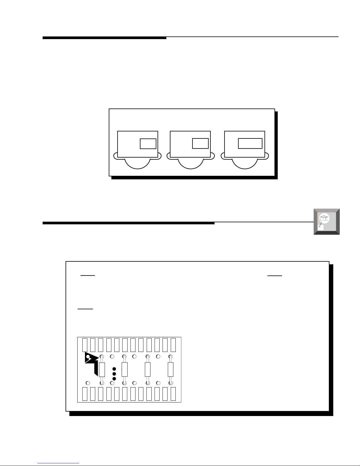
USING THE XCARD
↕
➝
➝
➝
➝
The crossover functions are controlled through the use of an XCard and can be set for high-pass, low-pass or full
range operation. The 100Hz XCard shipped with your amplifier is set for Full Range. Each crossover card has two
faces: one face operates Full Range, the other has arrows to indicate the edge for selecting HP (high-pass) or LP
(low-pass) operation. Orient the card with the desired operating edge, indicated by the arrow, toward the socket
terminals inside the amplifier. Firmly, but carefully, plug the card into the socket.
Low-Pass Full RangeHigh-Pass
LP
HP
HP
LP
CUSTOMIZING THE XCARD
The crossover point can be altered by changing the resistor value. Use the following formula to select the
appropriate resistor value to be placed on the XCard.
3386
f
o
7234
f
o
= R (in kΩ) for .047µf cap
= R (in kΩ) for .022µf cap
The actual formula is: R =
Where: R = Ω
FULL
1
2πfoc
fo = desired crossover frequency
c = capacitor in farads
ex: .047 x 10-6 for .047mf cap
a
O
▲
p
d
e
v
r
a
a
n
t
c
i
e
o
d
n
Crossover Card
High Pass
R1
Low Pass
Full Range
R2
R1
FULL
R2
– 13 –
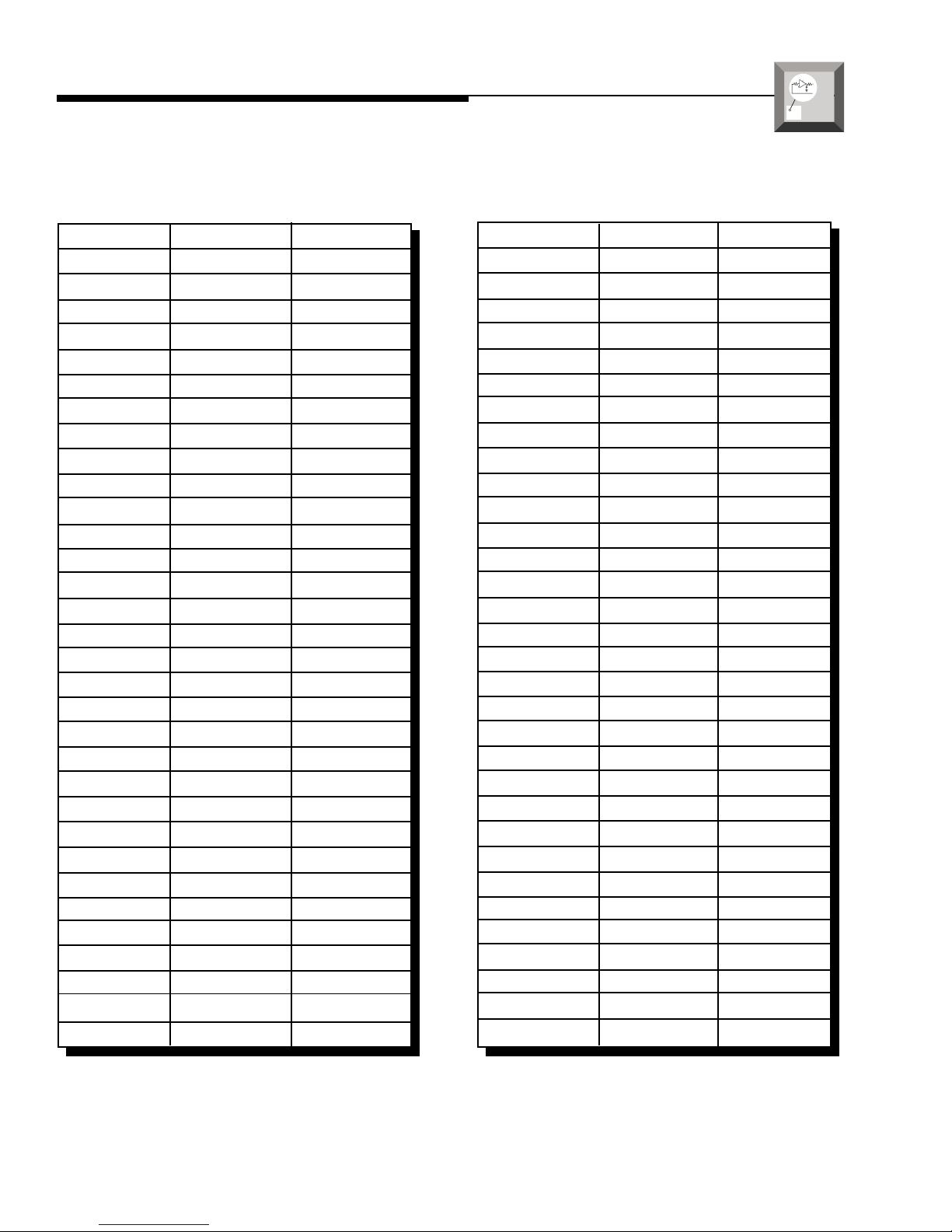
XCARD RESISTOR CHART
a
O
▲
p
d
e
v
r
a
a
n
t
c
i
e
o
d
n
Butterworth Alignment Q = .707
1% resistors used with 0.047
µµ
µF capacitors
µµ
Frequency R1 R2
20Hz 169kΩ 169kΩ
25Hz 133kΩ 133kΩ
30Hz 110kΩ 110kΩ
35Hz 95.3kΩ 95.3Ω
40Hz 84.5kΩ 84.5kΩ
45Hz 75kΩ 75kΩ
50Hz 68.1kΩ 68.1kΩ
55Hz 61.9kΩ 61.9kΩ
60Hz 56.2kΩ 56.2kΩ
65Hz 52.3kΩ 52.3kΩ
70Hz 48.7kΩ 48.7kΩ
75Hz 45.3kΩ 45.3kΩ
80Hz 42.2kΩ 42.2kΩ
84Hz 40.2kΩ 40.2kΩ
90Hz 37.4kΩ 37.4kΩ
200Hz 16.9kΩ 16.9kΩ
300Hz 11.3kΩ 11.3kΩ
400Hz 8.45kΩ 8.45kΩ
500Hz 6.65kΩ 6.65kΩ
600Hz 5.62kΩ 5.62kΩ
700Hz 4.75kΩ 4.75kΩ
800Hz 4.22kΩ 4.22kΩ
900Hz 3.74kΩ 3.74kΩ
1kHz 3.40kΩ 3.40kΩ
1.2kHz 2.80kΩ 2.80kΩ
2kHz 1.69kΩ 1.69kΩ
3kHz 1.10kΩ 1.10kΩ
4kHz 845Ω 845Ω
5kHz 665Ω 665Ω
6kHz 562Ω 562Ω
7kHz 487Ω 487Ω
8kHz 422Ω 422Ω
Butterworth Alignment Q = .707
5% resistors used with 0.047
µµ
µF capacitors
µµ
Frequency R1 R2
21Hz 160kΩ 160kΩ
26Hz 130kΩ 130kΩ
30.8Hz 110kΩ 110kΩ
37Hz 91kΩ 91Ω
41Hz 82kΩ 82kΩ
45Hz 75kΩ 75kΩ
49.8Hz 68kΩ 68kΩ
54.6Hz 62kΩ 62kΩ
60.5Hz 56kΩ 56kΩ
66.4Hz 51kΩ 51kΩ
72Hz 47kΩ 47kΩ
N/A N/A N/A
78.7Hz 43kΩ 43kΩ
86.8Hz 39kΩ 39kΩ
94Hz 36kΩ 36kΩ
212Hz 16kΩ 16kΩ
308Hz 11kΩ 11kΩ
413Hz 8.2kΩ 8.2kΩ
498Hz 6.8kΩ 6.8kΩ
605Hz 5.6kΩ 5.6kΩ
720Hz 4.7kΩ 4.7kΩ
787Hz 4.3kΩ 4.3kΩ
940Hz 3.6kΩ 3.6kΩ
1kHz 3.3kΩ 3.3kΩ
1.2kHz 2.7kΩ 2.7kΩ
2.1kHz 1.6kΩ 1.6kΩ
3kHz 1.1kΩ 1.1kΩ
4.1kHz 820Ω 820Ω
5kHz 680Ω 680Ω
6kHz 560Ω 560Ω
7.2kHz 470Ω 470Ω
7.9kHz 430Ω 430Ω
– 14 –
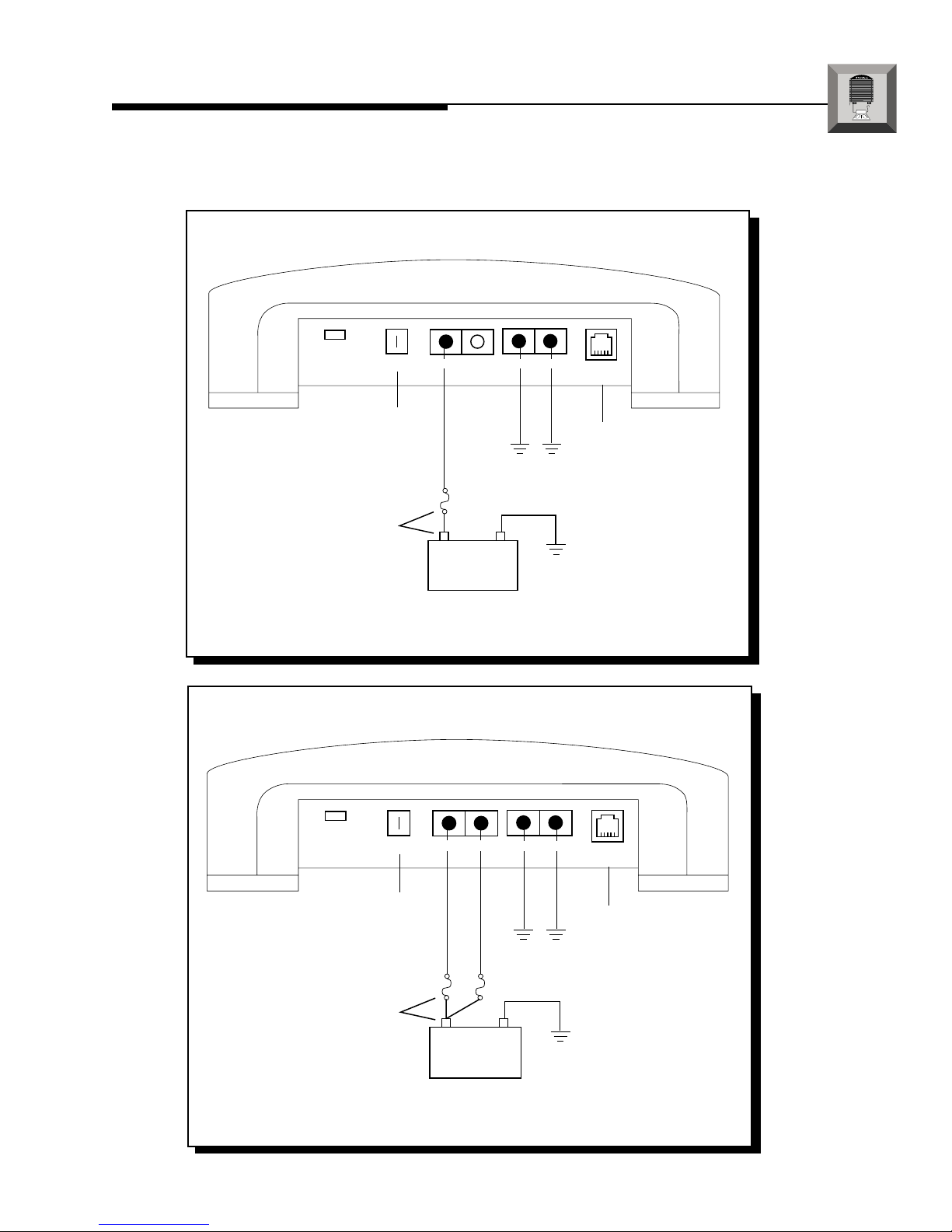
250X2 INSTALLATION
I
® ®
N
S
T
A
L
L
A
T
I
O
N
250x
Power Connections (Option #1)
2
Power
REM
Connect to remote
turn-on lead of
source unit.
Dual B+ Dual GND
Connect to chassis
ground of vehicle*
Less than 18"
+ –
Connect to B+ of battery
with a 60 amp fuse.
*Keep ground connections as close to each other as possible.
Punch Status
Display
Connect to
optional
PSD
250x2 Power Connections (Option #2)
Power
Less than 18"
*Keep ground connections as close to each other as possible.
REM
Connect to remote
turn-on lead of
source unit.
Connect to B+ of battery
with two 30 amp fuses.
Dual B+ Dual GND
Connect to chassis
ground of vehicle*
+ –
Punch Status
Display
Connect to
optional
PSD
– 15 –
 Loading...