

Page 1

RFX-8140
Installation Reference Sheet
Páginas de Referencia para la Instalación
Schéma d’Installation
Installations Beiblatt
Istruzioni di Installation
®®
Page 2
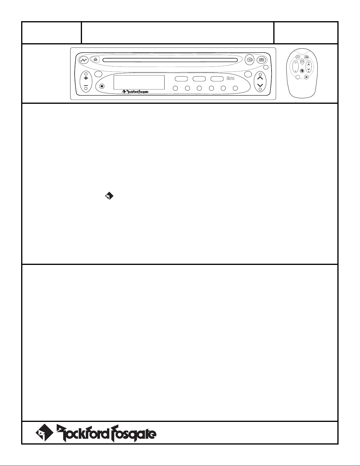
RFX-8140
VOL
AUD
PWR
Detachable Faceplate w/IR Remote
®®
RFX-8140
FEATURES
GENERAL
• ISO Mountable – 178mm x 50.4mm (trim ring removed)
• SMART-On (Sequentially Managed Accessory Remote
Turn-On) Separate turn-on leads for amplifiers and signal processors
that protect speakers and electronics from damaging transients
• Any Button Wake-Up
• Clock
• Cell Phone Mute
• Switchable Loudness – Enables bass response to be boosted at
low listening levels
AM / FM ST / CD Player / CD Changer Controller
• IR Remote Compatible w/ Pulse – Ability to operate
functions via remote control as well as trigger external devices (amp
racks, neon lights, etc.)
• Dimmable Dual Color Illumination – Green or Amber color
• Smart Power Antenna Output
AUDIO
phile
PREAMP
• Low Source Impedance – Enables multiple amplifiers to be
driven without signal loss
• 2-ch BAL/RCA Pre-Out – 6-pin Balanced or RCA
®
Specification
Reference
Sheet
+
–
CLOCK ILLUM
AUTO
P.SCN LOUDDSPL
RDMRPTSCAN PAUSED.SCN DIM
43 521
COMPACT
DIGITAL AUDIO
SEL
TUNE
6
®
1-6
• Source Tone Memory – Enables separate Bass and Treble
memory for different formats
• Dual External Audio Inputs – Allows the source unit to play
additional audio sources (VCR, video game, etc.)
• Signal Processor Loop – Allows an external processor to be
inserted before the source unit’s volume control
TUNER
• Gen 3.2 w/patented Digital Automatic Alignment
• MIR (Multipath Interference Rejection) – Improves audio
performance when radio reception is poor
• World Wide Tuner – America/Europe/Aust/Saudi
• 24 Station Presets – 6AM/18FM Presets
• Auto Store – Auto programming of all 24 presets
COMPACT DISC
• 5.0 Hologram laser w/multi-damping
• Dual 1 Bit D/A Converters w/8x Oversampling
• Digital Servo Control w/Auto Focus – Adjusts to CD
manufacturing tolerances for accurate tracking
SPECIFICATIONS
FM TUNER
Frequency Response ................................. 30Hz – 15kHz
Usable Sensitivity..........................................20dB @ 1uV
Alternate Ch. Selectivity ........................................... 90dB
Adjacent Ch. Selectivity ...........................................50dB
50dB Quieting Sensitivity........................................ 18dBf
Signal-to-Noise Ratio ...............................................72dB
Channel Separation...................................≥25dB @ 1kHz
Capture Ratio ................................................ 2.6 @ 45dBf
CD PLAYER
Usable Discs ..................................................... 5” and 3”
Frequency Response ...................... 20Hz – 20kHz (±2dB)
Signal-to-Noise Ratio .............................................>90dB
Channel Separation.................................................. 86dB
Dynamic Range .....................................................100dB
®®
AM TUNER
Sensitivity..........................31dBf max. @ 10dB sensitivity
–6dB Bandwidth .......................5kHz min. – 12kHz max.
GENERAL
Operating Voltage ............................... +10.5 to +16V DC
Pre-Out Voltage (vol. max.)................................ 8.5 Vrms
Preamp Output Impedance ....................................... 50Ω
Equalization ....................................... Bass ±8dB @ 60Hz
Treble ±10dB @ 10kHz
Chassis Dimensions ........................... 7"W x 63⁄8"D x 2"H
(178mm x 162mm x 50.4mm)
Nosepiece Dimensions ................... 71⁄16"W x 7⁄8"D x 2"H
(179.7mm x 22.2mm x 50.4mm)
Weight ................................................... 3.46 lbs. (1569g)
IR REMOTE
Dimensions............................... 29⁄16” W x 33⁄4” L x 3⁄4” H
(6.51cm x 9.53cm x 1.9cm)
Specifications subject to change without notice
Page 3
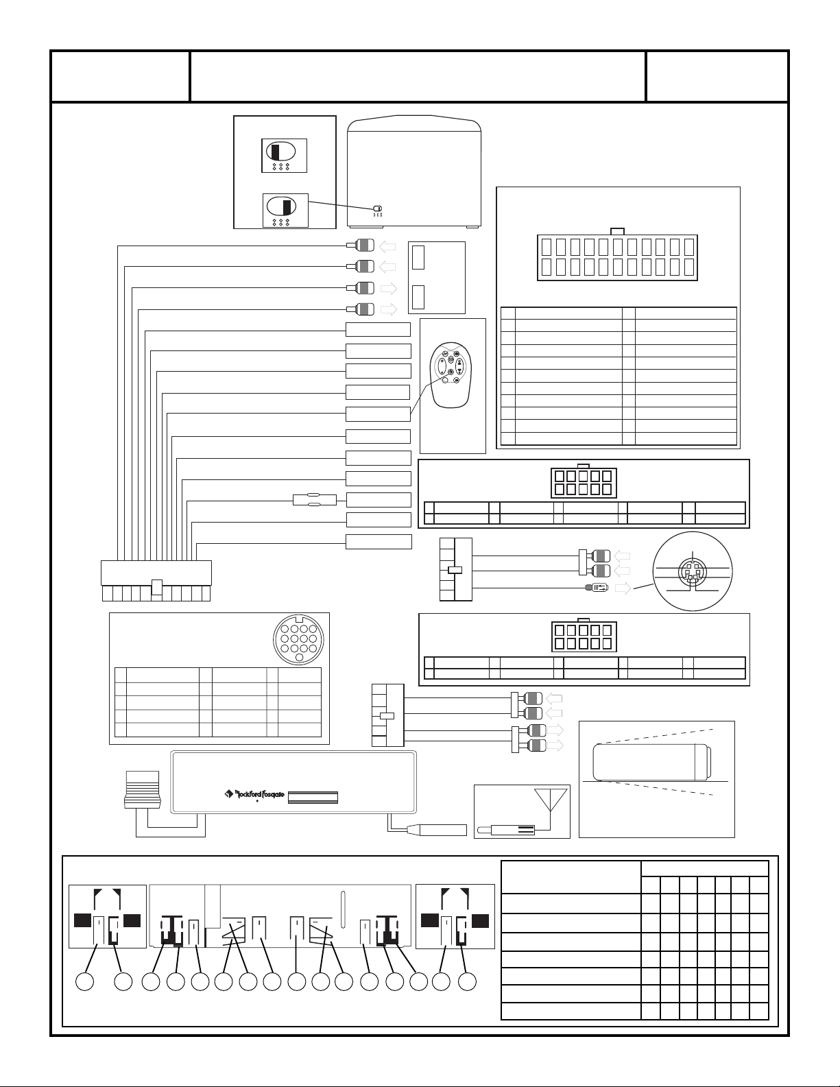
RFX-8140
AM / FM ST / CD Player / CD Changer Controller
Detachable Faceplate w/IR Remote
Installation
Reference
Sheet
The External Signal Processor
Loop is defaulted to the
BYPASS position.
To ENABLE the External
Signal Processor Loop,
remove the bottom cover and
adjust the selector switch.
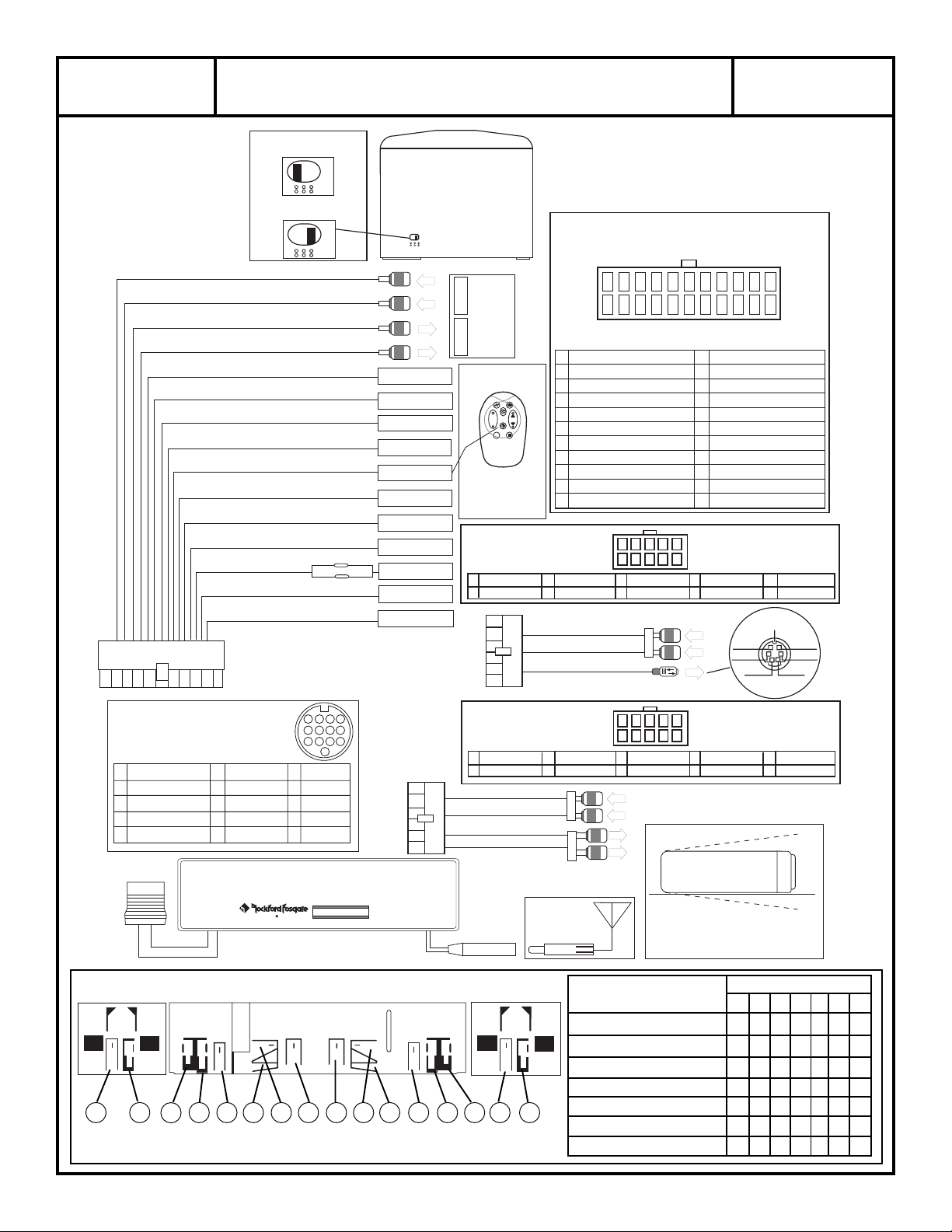
Signal Processor Loop (L) (Input)
Signal Processor Loop (R) (Input)
Signal Processor Loop (L) (Output)
Signal Processor Loop (R) (Output)
Dimmer Out (External Control) (Output)
Dimmer In (+12V to activate) (Input)
Ex Audio-2 (GND to activate) (Input)
Audio Mute (GND to activate) (Input)
Turn-On “C” (300mA Max) (Output)
(Pulsed 500ms)
Turn-On “B” (300mA Max) (Output)
(.5 sec DELAY ON – FAST OFF)
Turn-On “A” (2.0 Amp Max) (Output)
(FAST ON – .5 sec DELAY OFF)
Power Antenna (300mA Max) (Output)
Battery +12V (Input)
Ignition (switched +12V) (Input)
Chassis Ground (Input)
Signal Processor Loop
BYPASS
E
X
T
ENABLE
E
X
T
22-pin harness
Orange/White
Orange
Green/White
Brown
Blue/Red
Blue/White
Lt. Blue
Dk. Blue
10A Fuse
Yellow
Red
Black
Turn-On “B” = Amplifier(s)
Turn-On “A” = Signal Processor(s)
Radio
Remove Bottom Cover
10-pin harness
OUTIN
External
Signal
Processor
IR Remote
RFX-1110
Press “Diamond R”
Button to Pulse
Turn on “C”
Battery Replacement
(2) CR2032
Balanced DIN Harness
Ext Aud-1 (L–)
1
2
Ext Aud-1 (L+)
+
–
®
1-6
FA-1614-A
Ext. Aud-1 Input White (Left)
Ext. Aud-1 Input Red (Right)
Bal. Aud. Output (6-pin DIN)
22 21 20 19 18 17 16 15 14 13 12
1110987654321
(Looking into the Radio Connector)
1
N/C
2
Turn-On “B”
3
Turn-On “A”
4
Turn-On “C“
5
Audio Mute
6
Ex Audio-2
7
Sig. Processor Loop IN (R–)
8
Sig. Processor Loop OUT (R–)
9
Sig. Processor Loop IN (L–)
10
Sig. Processor Loop OUT (L–)
11
Chassis Ground
10
9
Ext Aud-1 (R–)
3
4
Ext Aud-1 (R+)
5
6
Power Harness
FA-1609-A
(Blue/White)
(Lt. Blue)
(Blue/Red)
(Brown)
(Green/White)
(Black)
432
8
6
1
7
5
DIN (R–)
DIN (R+)
G
R
E
E
N
12
N/C
13
Dimmer Out
14
Dimmer In
15
Ignition +12V
16
N/C
17
Pwr. Antenna
18
Sig. Processor Loop IN (R+)
19
Sig. Processor Loop OUT (R+)
20
Sig. Processor Loop IN (L+)
21
Sig. Processor Loop OUT (L+)
22
Battery +12V
DIN (L GND)
7
8
DIN (R GND)
(Orange/White)
(Orange)
(Red)
(Dk. Blue)
(Yellow)
(Looking into the
Radio Connector)
DIN (L–)
9
10
DIN (L+)
GND
Shield
+ R Signal
– R Signal
+ L Signal
– L Signal
NCNC
CD Changer/
Ex Audio-2 DIN
(Looking into the Changer DIN)
1
Right Signal (+)
2
Audio Common (–)
3
Left Signal (+)
4
Shield (Barrel)
5
Ground
6
N/C
7
N/C
8
N/C
9
N/C
10
Battery (+12V)
®®
RESET
4321
8765
12
11
E&C Data
12
N/C
13
N/C
11 10 9
13
Left Side View
G G C
C
C B F A D E E D
A
F B C
RCA Harness
Ext. Aud-1 (L–)
1
Ext. Aud-1 (L+)
2
Ext. Aud-1 Input White (Left)
Ext. Aud-1 Input Red (Right)
Audio Output White (Left)
Audio Output Red (Right)
Antenna
Input
Right Side ViewTop View
(Looking into the Radio
Left (–)
7
8
Right (–)
FA-1613-A
Ext Aud-1 (R–)
3
Ext Aud-1 (R+)
4
G
R
E
E
N
G
R
A
Y
Antenna
10
9
5
6
432
8
6
1
7
5
N/C
Right (+)
Minimum & Maximum
Mounting Angle
Instrument Panel Thickness Tabs to Bend
ABCDEFG
1.2mm to 2.5mm x x x
2.4mm to 3.5mm x x x
3.6mm to 4.5mm x x
4.6mm to 5.5mm x x x
5.6mm to 7.0mm x x
7.0mm to 12mm x x x
12.0mm to 15mm x x
Connector)
N/C
9
10
Left (+)
20°
20°
Page 4
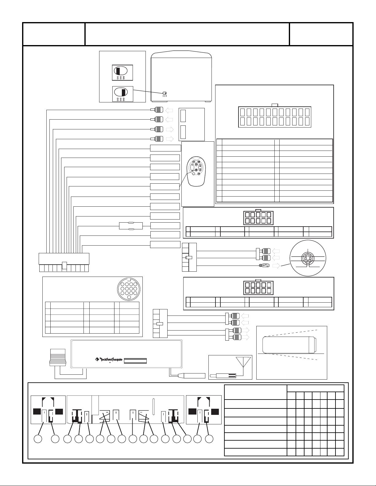
RFX-8140
AM/FM ST/Reproductor de CD’s/Controlador de Cargador de CD’s
Frontal Extraible con Mando a Distáncia
Páginas de Referencia
para la Instalación
La conexión del Procesador
de Señal Externo, está en
posición BYPASS por defecto.
Para Activar la conexión del
Procesador de Señal Externo,
Conexión del Procesador
de Señal
BYPASS
ACTIVADO
saque la tapa y ajuste el
communtador como proceda.
Entrada de la Conexión del Procesador de Señal (L)
Entrada de la Conexión del Procesador de Señal (R)
Salida de la Conexión del Procesador de Señal (L)
Salida de la Conexión del Procesador de Señal (R)
Salida de Dimmer (Control Externo) (Salida)
Entrada de Dimmer (+12V para ser activado)
(Entrada)
Audio Externo (GND para ser activado)
(Entrada)
Silenciador de Audio
(Entrada)
Encendido “C” (300mA Máx) (Salida)
(Pulsado 500ms)
Encendido “B” (300mA Máx) (Salida)
(Delay de 0.5 segundos conectado apagado Rápido)
Encendido “A” (2.0 Amp Máx) (Salida)
(Encendido Rápido Delay de 0.5 segundos desconcectado)
Alimentación de la Antena
(Máx 300mA (Salida)
Batería +12V (Entrada)
(GND para ser activado)
Fusible de
10 Amperios
Ignition (switched +12V) (Entrada)
T oma de tierra del Chasis (Entrada)
Encendido “B” = Amplificadore(s)
Encendido “A” = Procesador de Señal
E
X
T
E
X
T
Saque la tapa superior
Conector de 22 pines
Naranja/Blanco
Naranja
Verde/Blanco
Marrón
Azul/Rojo
Azul/Blanco
Azul Claro
Azul Oscuro
Amarillo
Rojo
Negro
Radio
Conector de 10 pines
SALIDA
Procesador
de Señal
Externo
ENTRADA
Mando a distancia
por Infrarrojos
RFX-1110
+
–
®
1-6
Pulse el botón R
Diamante para el
encendido “C”
Cambio de batería
(2) CR2032
Conector DIN
Balanceado
FA-1614-A
Ext Aud-1 (L–)
1
2
Ext Aud-1 (L+)
Ext. Aud-1 Entrada Blanco (Izquierda)
Ext. Aud-1 Entrada Rojo (Derecha)
Salida Balanceada de Audio
(Conector DIN de 6 pines)
22 21 20 19 18 17 16 15 14 13 12
1110987654321
(Mirando hacia el Conector de la Radio)
N/C
1
Encendido “B”
2
Encendido “A”
3
Encendido “C“
4
Silenciador de Audio
5
Audio Externo
6
Posterior (L–)
7
Posterior (R–)
8
Frontal (L–)
9
Frontal (R–)
10
Toma de tierra del chasis
11
Ext Aud-1 (R–)
3
4
Ext Aud-1 (R+)
Conector de Alimentación
FA-1609-A
N/C
(Azul/Blanco)
(Azul Claro)
(Azul/Rojo)
(Marrón)
(Verde/Blanco)
(Verde/Negro)
(Viloeta/Negro)
(Blanco/Negro)
(Gris/Negro)
(Negro)
8
10
9
7
DIN (R–)
5
6
DIN (R+)
12
Salida de Dimmer
13
14
Entrada de Dimmer
15
Alimentación +12V
16
N/C
17
Alimentación de la Antena
18
Posterior (L+)
19
Posterior (R+)
20
Frontal (L+)
21
Frontal (R+)
22
Batería +12V
432
6
1
5
V
E
R
D
E
Conector de la Radio)
DIN (L GND)
7
8
DIN (R GND)
(Mirando hacia el
+R Señal
– R Señal
(Naranja/Blanco)
(Naranja)
(Rojo)
(Azul Oscuro)
(Verde)
(Violeta)
(Blanco)
(Gris)
(Amarillo)
DIN (L–)
9
10
DIN (L+)
Tierra
Blindaje
+ L Señal
– L Señal
NCNC
Cambiador de CD's/
Conector DIN EX Audio-2
(Mirando hacia el Cambiador de CD's)
6
Señal Derechal (+)
1
Común Audio (–)
2
Señal Izquierda (+)
3
Blindaje (Protección)
4
Tierra
5
Vista lateral desde
la Izquierda
G G C
C
C B F A D E E D
N/C
7
N/C
8
N/C
9
N/C
10
Battería (+12V)
®®
4321
8765
12
11 10 9
13
Datos E/C
11
N/C
12
N/C
13
RESET
Vista en planta
Ext. Aud-1 Entrada Blanco (Izquierda)
Ext. Aud-1 Entrada Rojo (Derecha)
Salida de Audio Blanco (Izquierda)
Salida de Audio Rojo (Derecha)
A
F B C
Ext. Aud-1 (L–)
1
Ext. Aud-1 (L+)
2
Entrada de
Antena
Vista lateral desde
la Derecha
Conector RCA
FA-1613-A
3
4
Antena
Amplitud del panel Lengüetas a doblar
(Mirando hacia el
Conector de la Radio)
Izquierda (–)
Derecha (–)
9
10
Ext Aud-1 (R–)
Ext Aud-1 (R+)
V
E
R
D
E
G
R
I
S
10
9
N/C
5
6
Derecha (+)
432
8
6
1
7
5
7
8
Ángulos Máximo y
Mínimo para montaje
de instrumental
1.2mm to 2.5mm x x x
2.4mm to 3.5mm x x x
3.6mm to 4.5mm x x
4.6mm to 5.5mm x x x
5.6mm to 7.0mm x x
7.0mm to 12mm x x x
12.0mm to 15mm x x
ABCDEFG
N/C
Izquierda (+)
20°
20°
Page 5
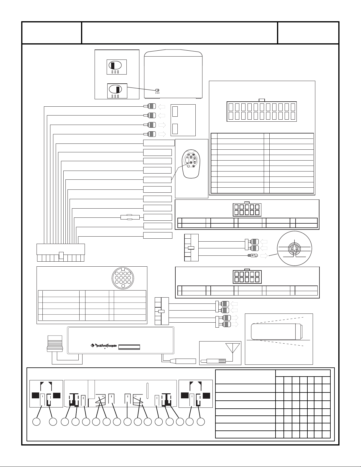
RFX-8140
OM / FMST Lecteur CD / Commande Changeur CD
Face détachable avec télécommande IR
Schéma
d’Installation
La
Boucle du Processeur de
Signal
est en position
désactivée d'origine.
Pour activer la
Processeur de Signal
Boucle du
, enlever
le couvercle du fond et ajuster
le commutatuer.
Boucle Processeur de Signal
Boucle Processeur de Signal
Boucle Processeur de Signal
Boucle Processeur de Signal
Dimmer (Contrôle externe) (Sortie)
Dimmer (+12V pour activer) (Entrée)
Audio Externe (commande négative) (Entrée))
Atténuateur audio (mute) – commande
négative (Entrée)
Commande “C” (300mA Max) (Sortie)
(Impulsion 500mA)
Commande “B” (300mA Max) (Sortie)
(Délai d'allumage 0,5s – coupure rapide)
Commande “A” (2,0A Max) (Sortie)
(Allumage rapide – Délai de coupure 0,5s)
Antenne Electrique (300mA Max) (Sortie)
Batterie +12V (Entrée)
+15 Allumage (Entrée)
Masse Chassis (Entrée)
Boucle Processeur de Signal
DESACTIVE
E
X
T
ACTIVE
E
X
T
(G)
(D)
(G)
(D)
Connecteur 22-broches
Fusible 10A
Commande “B” = Amplificateur(s)
Commande “A” = Processeur(s) de signal
Enlever le couvercle du fond
Radio
Connecteur 10-broches
OUTIN
Processeur
de signal
externe
Orange/Blanche
Télécommande IR
Orange
Vert/Blanche
Brun
Bleu/Rouge
Bleu/Blanche
Appuyer sur le bouton
rouge “Losange R” pour
activer la commande “C.”
Bleu clair
Bleu foncé
Jaune
Rouge
Connecteur DIN BLT
1
2
Noir
RFX-1110
+
–
®
1-6
Batterie de
remplacement
(2) CR2032
FA-1614-A
Aud Ext-1 (G–)
Aud Ext-1 (G+)
Entrée Aud. Ext. blanc (G)
Entrée Aud. Ext. rouge (D)
Sortie Audio BLT (DIN 6 broches)
22 21 20 19 18 17 16 15 14 13 12
1110987654321
1
N/C
2
Commande “B”
3
Commande “A”
4
Commande “C“
5
Atténuateur audio
6
Audio-2
Processeur Signal IN (D–)
7
Processeur Signal OUT (D–)
8
Processeur Signal IN (G–)
9
Processeur Signal OUT (G–)
10
Masse chassis
11
Aud Ext-1 (D–)
3
4
Aud Ext-1 (D+)
Cablage HP/Alimentation
FA-1609-A
(Vue sur le connecteur de la radio)
12
N/C
13
Sortie Dimmer
14
Entrée Dimmer
15
Allumage +12V
16
N/C
17
Antenne Electrique (Bleu Foncé)
18
Processeur Signal (D+)
19
Processeur Signal
20
Processeur Signal
21
Processeur Signal
22
Batterie +12V
(Vue sur le connecteur
DIN (G GND)
DIN (D GND)
Signal +D
Signal –D
de la radio)
1
7
8
10
9
5
6
(Bleu/Blanc)
(Bleu clair)
(Bleu/Rouge)
(Brun)
(Vert/Blanc)
(Noir)
8
6
7
5
DIN (D–)
DIN (D+)
V
E
R
T
432
(Orange/Blanc)
(Orange)
(Rouge)
(D+)
IN (G+)
OUT (G+)
(Jaune)
9
DIN (G–)
10
DIN (G+)
Blindage
Signal +G
Signal –G
NCNC
DIN Changeur CD/
Ex Audio-2 DIN
(Vue sur le DIN du Changeur)
1
Signal positif droite (+)
2
Commun négatif signal (–)
3
Signal positif gauche (+)
4
Blindage
5
Masse
6
N/C
7
N/C
8
N/C
9
N/C
10
Batterie +12V
®®
RESET
4321
8765
12
11
Données E&C
12
N/C
13
N/C
11 10 9
13
Vue de gauche
G G C
C
C B F A D E E D
A
F B C
Cablage RCA
FA-1613-A
Aud Ext-1 (G–)
1
Aud Ext-1 (G+)
2
Ext. Aud-1 Entrée Blanc (G)
Ext. Aud-1 Entrée Rouge (D)
(Droite)
Sortie Audio blanc (G)
Sortie Audio rouge (D)
Fiche
Antenne
Vue de droiteVue du haut
(Vue sur le connecteur
de la radio)
7
Gauche (–)
8
Droite (–)
9
10
Angle de montage
N/C
Gauche (+)
20°
20°
Aud Ext-1 (D–)
3
Aud Ext-1 (D+)
4
V
E
R
T
G
R
I
S
Antenne
10
9
5
6
8
6
7
5
N/C
Droite (+)
432
1
maximum et minimum
Epaisseur du tableau de bord Languettes à plier
ABCDEFG
1.2mm to 2.5mm x x x
2.4mm to 3.5mm x x x
3.6mm to 4.5mm x x
4.6mm to 5.5mm x x x
5.6mm to 7.0mm x x
7.0mm to 12mm x x x
12.0mm to 15mm x x
Page 6
RFX-8140
AM / FM ST / CD-Spieler/CD-Wechsler-Steuerungsgerät
Abnehmbares Bedienteil/IR Fernbedienung
Installations
Beiblatt
Die externe Prozessor Siganl-
Prozessor Signal-Schleife
Schleife (ist Voreingestellt auf
Bypass Position)
Um die externe Signalschleife
einzuschalten, müssen Sie das
Bedienteil abnehmen und
den Wählschalter umstellen
Prozessor Signal-Schleife (L) (Eingang)
Prozessor Signal-Schleife (R) (Eingang)
Prozessor Signal-Schleife (L) (Ausgang)
Prozessor Signal-Schleife (R) (Ausgang)
Dimmer Ausgang (Externe Kontrolle) (Ausgang)
Dimmer In (+12V zum aktivieren) (Eingang)
Audio (GND zum activieren) (Eingang)
Stummschaltung (GND zum aktivieren)
(Eingang)
Einschaltstrom “C” (300mA Max)(Ausgang)
(Pulsed 500ms)
Einschaltstrom “B” (300mA Max)(Ausgang)
(.5 sec Einschaltverzögerung-Schnelles Ausschalten)
Einschaltstrom
(Schnelles Einschalten – .5 sec Ausschaltverzögerung)
“A” (2.0 Amp Max) (Ausgang)
Motor Antenne (300mA Max) (Ausgang)
Batterie +12V (Eingang)
Zündung (schaltbar +12V) (Eingang)
Karosserie Masse (Eingang)
Einschaltstrom “B” = Verstärker(s)
Einschaltstrom “A” = Signal Prozessor(s)
Bypass
eingeschaltet
10A Sicherung
E
X
T
E
X
T
Taste zum Lösen des
22-pin Stecker
Bedienteils
10-pin Stecker
Strom Stecker
FA-1609-A
22 21 20 19 18 17 16 15 14 13 12
1110987654321
(Blick in den Radio Anschluβ)
12
1
N/C
2
Einschaltstrom “B”
3
Einschaltstrom “A”
4
Einschaltstrom “C“
5
Stummschaltung
6
Audio-2
7
Sig. Processor Loop IN (R–)
8
Sig. Processor Loop OUT (R–)
9
Sig. Processor Loop IN (L–)
(Blau/Weiβ)
(Hellblau)
(Blau/Rot)
(Braun)
(Grün/Weiβ)
Sig. Processor Loop OUT (L–)
Karosserie Masse
10
9
5
6
(Schwarz)
8
6
7
5
DIN (R–)
DIN (R+)
G
R
Ü
N
432
N/C
13
Dimmer Ausgang
14
Dimmer In
15
Ignition +12V
16
N/C
17
Motor Antenne
18
Sig. Processor Loop IN (R+)
19
Sig. Processor Loop OUT (R+)
20
Sig. Processor Loop IN (L+)
21
Sig. Processor Loop OUT (L+)
22
Batterie +12V
(Blick in den Radio
DIN (L GND)
DIN (R GND)
+ R Signal
– R Signal
Anschluβ)
1
7
8
(Orange/
(Orange)
(Rot)
(Dunkelblau)
(Gelb)
DIN (L–)
9
10
DIN (L+)
MasseSchirm
NCNC
+ L Signal
– L Signal
Weiβ)
Orange/Weiβ
Orange
Grün/Weiβ
Braun
Blau/Rot
Blau/Weiβ
Hellblau
Dunkelblau
Gelb
Rot
Schwarz
Externer
Ausgang
Signalprozessor
Eingang
IR Fernbedienung
RFX-1110
+
–
®
1-6
Drücke “Diamond R”
Taste, um auf “C”
Einschaltimpuls zu geben
Ersatzbatterien
(2) CR2032
10
11
Balanced DIN Harness
FA-1614-A
Ext Aud-1 (L–)
1
2
Ext Aud-1 (L+)
Ext Aud-1 (R–)
3
4
Ext Aud-1 (R+)
Ext. Aud-1 Eingang weiβ (links)
Ext. Aud-1 Eingang rot (rechts)
Bal. Aud. Augang (6-pin DIN)
CD Wechsler/Ex Audio DIN
(Blick in den CD Anschluβ)
1
Rechtes Signal (+)
2
Audio gesamt (–)
3
Linkes Signal (+)
4
Abschirmung
5
Masse
6
N/C
7
N/C
8
N/C
9
N/C
10
Batterie +12V
®®
RESET
12
11
12
13
4321
8765
11 10 9
13
E&C Daten
N/C
N/C
RCA Adapter
FA-1613-A
Ext. Aud-1 (L–)
1
Ext. Aud-1 (L+)
2
Ext. Aud-1 Eingang weiβ (links)
Ext. Aud-1 Eingang rot (rechts)
Audio Ausgang weiβ (links)
Audio Ausgang rot (rechts)
Antenneneigang
Linke
Seitenansicht
G G C
C
C B F A D E E D
Draufsicht
A
F B C
Rechte
Weitenansicht
Ext Aud-1 (R–)
3
Ext Aud-1 (R+)
4
G
R
Ü
N
G
R
A
U
Antenne
432
8
6
10
9
5
6
7
5
N/C
Rechte (+)
1
Minimaler & Maximaler
Linke (–)
7
8
Rechte (–)
(Blick in den Radio
Anschluβ)
N/C
9
10
Linke (+)
20°
20°
Einbauwinkel
Dicke des Instumenten-Panels Klammern zu biegen
ABCDEFG
1.2mm to 2.5mm x x x
2.4mm to 3.5mm x x x
3.6mm to 4.5mm x x
4.6mm to 5.5mm x x x
5.6mm to 7.0mm x x
7.0mm to 12mm x x x
12.0mm to 15mm x x
Page 7
RFX-8140
AM / FM ST / CD Player / CD Changer Controller
Frontalino Estraibile con Telecomando
Istruzioni di
Installazione
Il loop del processore di
Loop del processore
segnale é in posizione
BYPASS dalla fabbrica.
Per abilitare il loop del
processore di segnale esterno,
togliere il coperchio inferiore
e regolare lo switch.
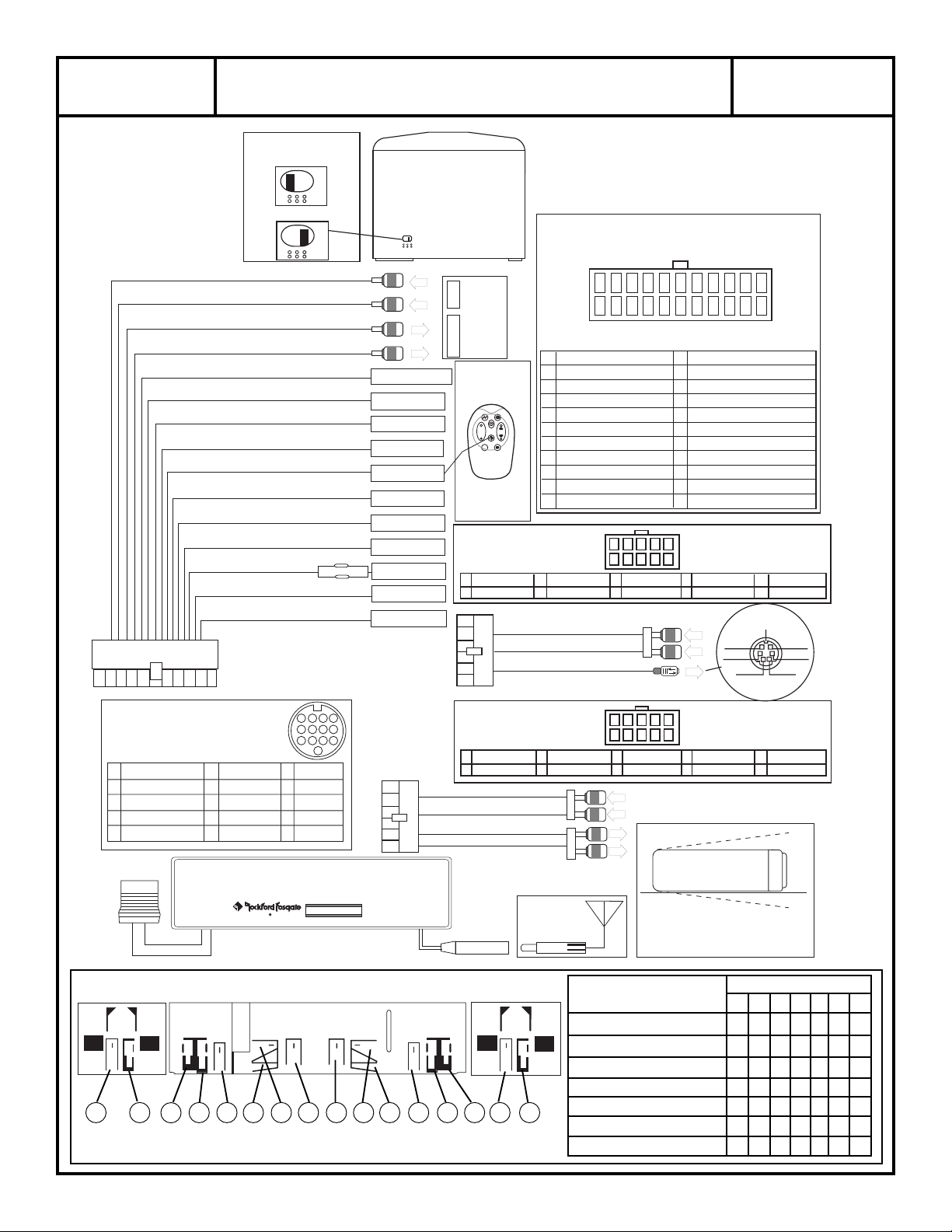
Loop del processore di segnale (L) (Ingresso)
Loop del processore di segnale (R) (Ingresso)
Loop del processore di segnale (L) (Uscita)
Loop del processore di segnale (R) (Uscita)
Uscita dimmer (Controllo esterno) (Uscita)
Ingresso dimmer (+12V per attivare) (Ingresso)
Audio-2 est. (massa per attivare) (Ingresso)
Audio Mute (massa per attivare) (Ingresso)
Consenso “C” (300mA Max) (Uscita)
(Impulsi 500mSec)
Consenso “B” (300mA Max) (Uscita)
(Accensione ritardo 0,5 sec, spegnimento immediato)
Consenso “A” (2.0 Amp Max) (Uscita)
(Accensione immediata, ritardo 0,5 sec spegnimento)
Antenna Elettrica (300mA Max) (Uscita)
+12V batteria
(Ingresso)
Ignition (switched +12V) (ingresso)
Massa del telaio (ingresso)
Consenso “B” = Amplificatore
Consenso “A” = Processore di Signale
di segnale
BYPASS
ATTIVO
E
X
T
E
X
T
Fusibile 10A
Radio Rimuovere il
coperchio inferiore
Connessione 22 cavi Connessione 10 cavi
USCITA
Processore
di segnale
esterno
INGRESSO
Arancione/Bianco
Arancione
Verde/Bianco
Marrone
Blu/Rosso
Blu/Bianco
Azzurro
Blu scuro
Giallo
Rosso
Nero
Telecomando
infrarossi
RFX-1110
+
–
®
1-6
Premere il tasto
“DIAMOND R” per
il consenso “C”
Sostituzione batteria
(2) CR2032
Cavo DIN bilanciato
FA-1614-A
Aud est.-1 (L–)
1
2
Aud est. 1 (L+)
Audio est.-1 Ingresso Bianco (sinistro)
Audio est.-1 Ingresso Rosso (destro)
Bal. Aud. Uscita (6-pin DIN)
Connettore di alimentazione
22 21 20 19 18 17 16 15 14 13 12
1110987654321
(Guardando il connettore della radio)
N/C
1
Consenso “B”
2
Consenso “A”
3
4
Consenso “C“
5
Audio Mute
6
Esterno Audio
IN loop del processore (R–)
7
OUT loop del processore (R–)
8
IN loop del processore (L–)
9
OUT loop del processore (L–)
10
Massa del telaio
11
Aud est.-1 (R–)
3
4
Aud est.-1 (R+)
(Blu/Bianco)
(Azzurro)
(Blu/Rosso)
(Marrone)
(Verde/Bianco)
(Nero)
10
9
DIN (R–)
5
6
DIN (R+)
FA-1609-A
432
8
6
7
5
V
E
R
D
E
12
N/C
13
Dimmer Out
14
Dimmer In
15
Ignition +12V
16
N/C
17
Pwr. Antenna
18
IN loop del processore (R+)
19
OUT loop del processore
20
IN loop del processore
21
OUT loop del processore
22
+12V batteria
(Guardando il connettore
DIN (L GND)
7
8
DIN (R GND)
della radio)
+ R Segnale
– R Segnale
1
(Arancione/Bianco)
(Arancione)
(Rosso)
(Blu Scuro)
(R+)
(L+)
(L+)
(Giallo)
DIN (L–)
9
10
DIN (L+)
Massa
Schermo
+ L Segnale
– L Segnale
NCNC
CD Changer/
DIN Audio-2 Est
(Vista del DIN del changer)
1
Signale destro (+)
2
Comune audio (–)
3
Signal sinistro (+)
4
Schermo
5
Massa
6
7
8
9
10
N/C
N/C
N/C
N/C
+12V Batteria
®®
RESET
4321
8765
12
E&C Data
11
N/C
12
N/C
13
11 10 9
13
Vista da sinistra
G G C
C
C B F A D E E D
A
F B C
Connettore RCA
FA-1613-A
Aud est.-1 (L–)
1
Audio est.-1
2
Audio est.-1 Ingresso Bianco (Sinistro)
Audio est.-1 Ingresso Rosso (Destro)
Audio Uscita Bianco (Sinistro)
Audio Uscita Rosso (Destro)
Ingresso
Antenna
Vista da destraVista dall’alto
432
(Guardando il connettore
Sinistro (–)
7
8
Destro (–)
della radio)
1
Angolo minimo e
9
10
N/C
Sinsitro (+)
20°
20°
(L+)
Aud est.-1 (R–)
3
Aud est.-1 (R+)
4
Antenna
8
6
10
9
7
5
N/C
5
6
Destro (+)
V
E
R
D
E
G
R
I
G
I
O
massimo di installazione
Spessore del pannello Alette da piegare
ABCDEFG
1.2mm to 2.5mm x x x
2.4mm to 3.5mm x x x
3.6mm to 4.5mm x x
4.6mm to 5.5mm x x x
5.6mm to 7.0mm x x
7.0mm to 12mm x x x
12.0mm to 15mm x x
Page 8
ENGLISH
World Wide Tuner
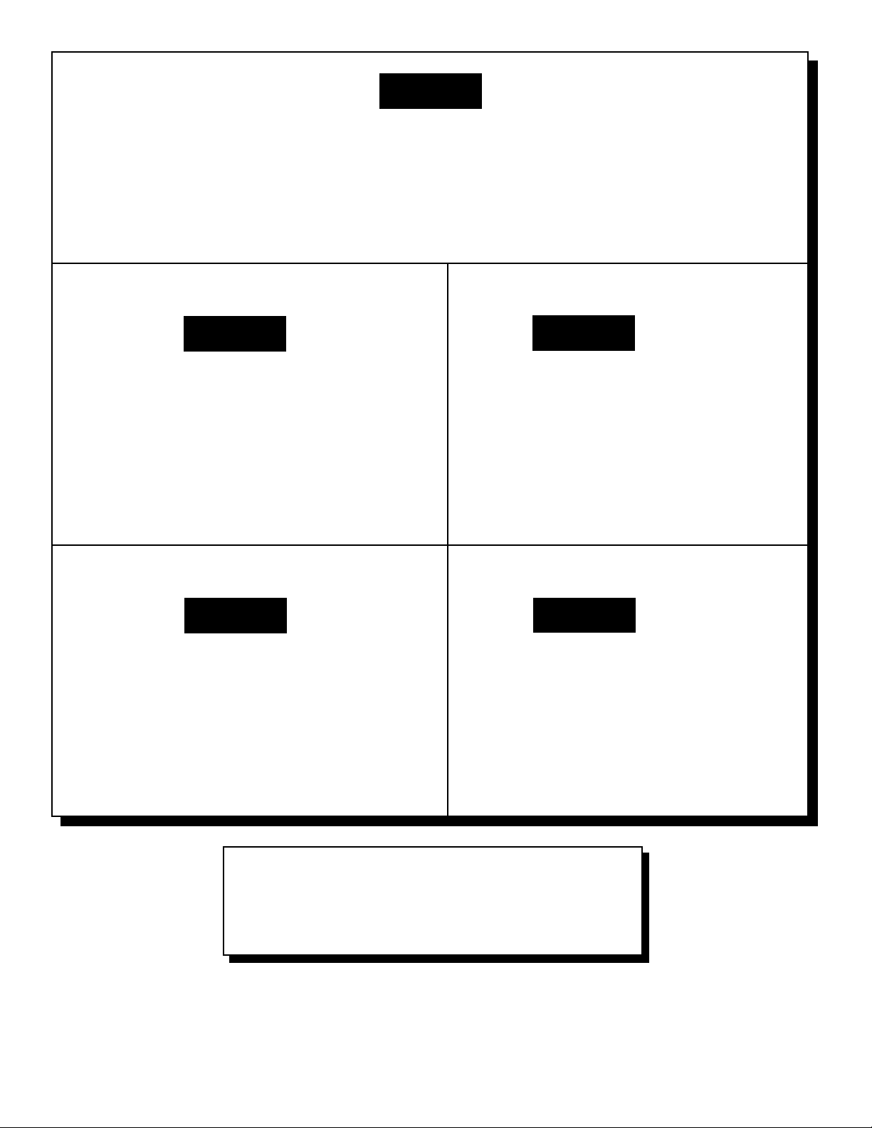
The frequency band on the tuner can be programmed
to conform with different country codes (except Japan)
1.Press and hold DSPL for two seconds
2. Press SINE WAVE (Tuner)
3. Press SEL to cycle through AMERICAS, EUR/
AUST and SAUDI
ESPAÑOL
Sintonizador Standard Mundial
La banda de frecuencias del sintonizador puede ser
programda para ser compatible con los diferentes códigos
de los países (excepto Japón)
1.Mantenga pulsado el botón DSPL durante dos
segundos
2.Pulse el botón con la onda senoidal (Radio)
3.Pulse SEL para cambiar secuencialmente entre
AMERICAS, EUROPA/AUSTRALIA y ARABIA SAUDI
DEUTSCH ITALIANO
Weltweiter Tuner
Das Frequenzband des Tuners kann programmiert
werden, um in den verschiedenen Ländern einwandfrei
zu funktionieren (ausgenommen Japan).
1.Drücken und halten Sie DSPL für zwei Sekunden
2.Drücken Sie SINE WAVE (Tuner)
3.Drücken Sie SEL, um zwischen AMERICAS, EUR/
AUST und SAUDI umzuschalten
FRANÇAIS
World Wide Tuner
La bande de fréquence peut être programmé pour
convenir au codes des différent pays (excepté le Japon).
1.Enfoncez et tenez DSPL enfoncé durant deux
secondes
2. Enfoncez SINE WAVE (Tuner)
3. Enfoncez SEL pour parcourir AMERICAS, EUR/
AUST et SAUDI
Sintonizzatore a copertura mondiale
Le bande di frequenza del sintonizzatore possono
essere programmate per adeguarsi ai diversi sistemi
dei paesi (Giappone escluso).
1.Tenere premuto DSPL per 2 secondi
2.Premere il tasto Onda Sinusoidale (Tuner)
3.Premere piú volte SEL per selezionare tra AMERICAS, EUR/AUST e SAUDI
Nota: per l'Italia selezionare EUR/AUST
MAN-1607-A
3/97
MADE IN MEXICO
Designed and Engineered in the USA
by Delco Electronics and Rockford Fosgate
This product was assembled by Delco Electronics at Deltronicos de Matamoros,
Mexico. Due to the global nature of their manufacturing facilities and the electronics
parts industry in general, some parts may be manufactured in other countries.
Rockford Fosgate
Rockford Corporation
546 South Rockford Drive
Tempe, Arizona 85281 U.S.A.
In U.S.A., (602) 967-3565
In Europe, Fax (49) 4207-801250
In Japan, Fax (81) 559-79-1265
 Loading...