

Page 1
RFT-1081RFT-1081
RFT-1081
RFT-1081RFT-1081
RFT-1101RFT-1101
RFT-1101
RFT-1101RFT-1101
“The Box“The Box
“The Box
“The Box“The Box
That Rocks”That Rocks”
That Rocks”
That Rocks”That Rocks”
® ®
car audio
for
fanatics
Installation Reference Sheet
Páginas de Referencia para la Instalación
Schéma d’Installation
Installations Beiblatt
Istruzioni di Installation
®
Page 2
RFT-1081
RFT-1101
ENCLOSURE
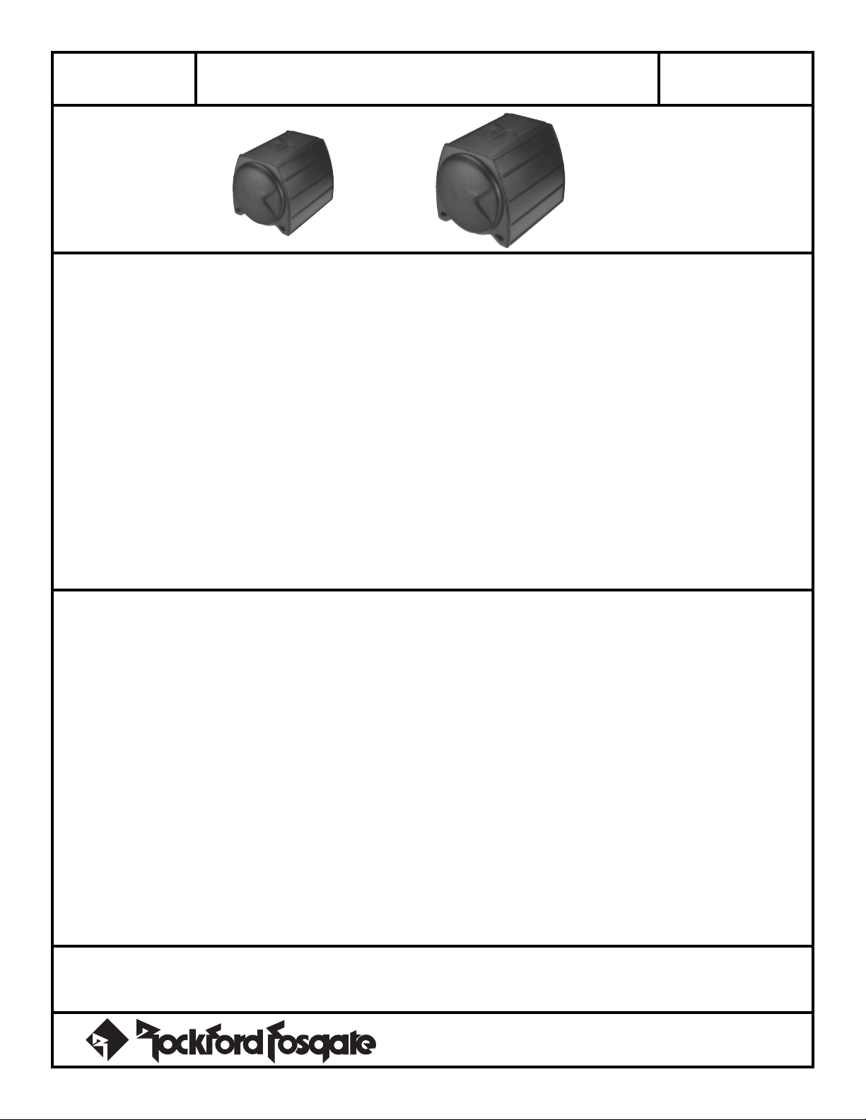
8” Box That Rocks
10” Box That Rocks
RFT-1081 RFT-1101
FEATURES
PUNCH WOOFER
Specification
Reference
Sheet
• Roto-Mold Construction – The use of Roto-Mold manufacturing
produces a composite enclosure with seamless construction. This greatly
increases rigidity to prevent the enclosure from flexing and allows custom
designs to be fabricated. The result is a radical, stronger, more reliable
enclosure.
• Acoustic Suspension Enclosure– The Subz enclosure uses an
acoustic suspension design (sealed) for optimum performance. The
enclosure is matched to the woofer for deep bass output while requiring
minimal operating space.
• Anti-Tip Design – The enclosure has a flat bottom to provide a solid
foundation for securing it to the vehicle and prevent it from rolling.
SPECIFICATIONS
RFT-1081
Frequency Response ..............................................30Hz-400Hz
Enclosure Vb (ft3 / liter).......................................... 0.35 (9.91L)
Baffle Thickness............................................................. 0.300”
Speaker Model ..........................................................RFP-1408
Nominal Impedance.............................................................4Ω
Fs ...................................................................................30Hz
RE ..................................................................................3.6Ω
LE................................................................................ 2.5mH
QMS................................................................................ 4.89
QES ................................................................................ 0.32
QTS................................................................................. 0.30
VAS (ft3 / liter)........................................................... 0.883/25L
XMAX (in/mm) ........................................................0.32”/8mm
SPL (dB @ 1w/1m) ..........................................................85dB
Power Handling (RMS/Peak) ................................. 200W/400W
Speaker Displacement (ft3 / liter).............................. 0.05/1.416L
Overall Dimensions ...........................99⁄16”H x 103⁄16”W x 127⁄16”L
(24.29cm x 25.87cm x 31.59cm)
Weight ........................................................ 13.5 lbs. (6.12kg)
• PVA Cone – The cone material used is a spruce pulp paper and provides
the necessary combination of weight and strength to allow high levels of
output without cone break up. The cone is also treated with a water
resistant PolyVinyl Acetate (PVA) emulsion which increases cone rigidity
and lowers distortion.
• Aluminum Voice Coil Former – The voice coil is made of multiple
layers of copper wound on a black, anodized, aluminum former. This
improves the speaker’s power handling by efficiently dissipating heat from
the voice coil.
• Hyper-Extended Pole Piece – The pole piece has been extended to
provide a more linear magnetic field for the operation of the woofer. This
lowers distortion and provides the woofer with better low frequency
response.
• Vented Bumped Back Plate – The back plate has been stepped
deeper to allow the woofer more excursion for harder hitting bass.
Additionally, the back plate is vented with a radiused aerodynamic vent that
efficiently and quietly keeps the voice coil cool.
RFT-1101
Frequency Response ..............................................24Hz-400Hz
Enclosure Vb (ft3 / liter) ....................................... 0.81 (22.94L)
Baffle Thickness............................................................. 0.300”
Speaker Model ..........................................................RFP-1410
Nominal Impedance.............................................................4Ω
Fs ...................................................................................24Hz
RE ..................................................................................3.6Ω
LE................................................................................ 2.5mH
QMS................................................................................ 4.08
QES ................................................................................ 0.27
QTS................................................................................. 0.25
VAS (ft3 / liter)............................................................. 2.72/77L
XMAX (in/mm) ........................................................0.32”/8mm
SPL (dB @ 1w/1m) ..........................................................87dB
Power Handling (RMS/Peak) ................................. 200W/400W
Speaker Displacement (ft3 / liter).............................. 0.06/1.699L
Overall Dimensions ............................ 117⁄8”H x 125⁄8”W x 155⁄8”L
(30.16cm x 32.07cm x 39.69cm)
Weight ........................................................ 17.8 lbs. (8.07kg)
ACCESSORY PACK
(2) Nylon Straps (4) Plastic Mounting Brackets (8) Mounting Screws
®®
– 1 –
Specifications subject to change without notice
Page 3
RFT-1081
RFT-1101
8” Box That Rocks
10” Box That Rocks
Installation
Reference
Sheet
WARNING: PLEASE FOLLOW THESE INSTRUCTIONS CAREFULLY. FAILURE TO FOLLOW THESE INSTRUCTIONS OR TO INSTALL
THE ENCLOSURE PROPERLY COULD RESULT IN DETACHMENT OF THE ENCLOSURE AND SERIOUS INJURY.
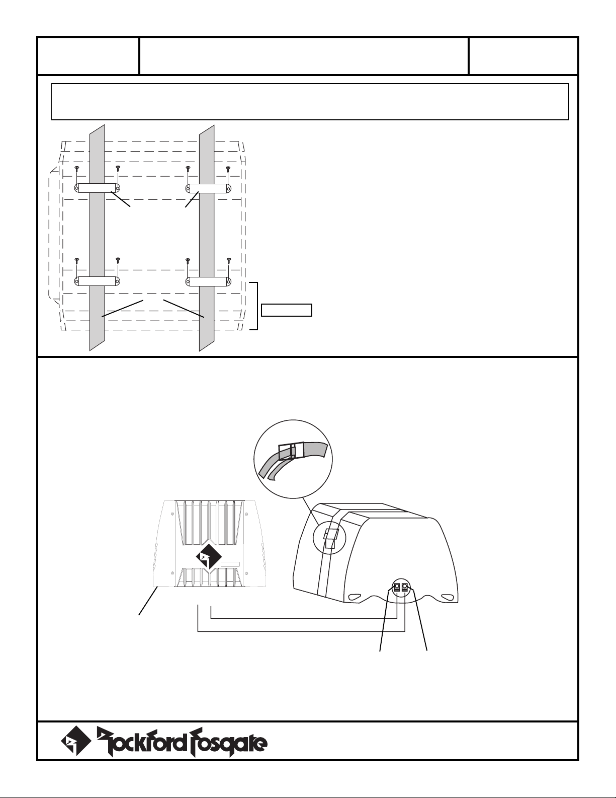
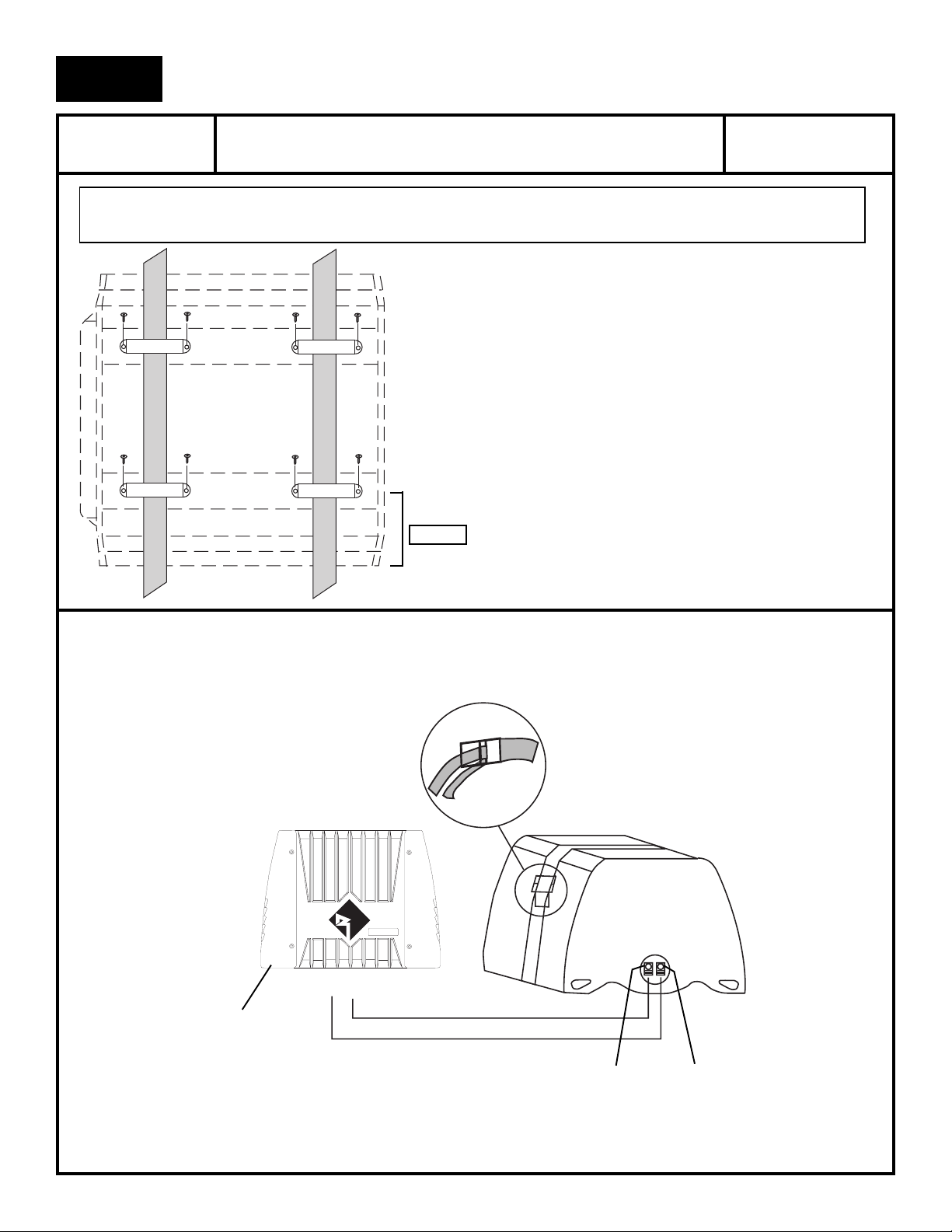
1. INSTALL THE MOUNTING BRACKETS
Place the enclosure in the desired mounting location and position the mounting
brackets approximately 4” from each end. Push the mounting brackets as close as
possible to the enclosure without moving or lifting it. Carefully remove the enclosure
and secure the brackets using the supplied screws.
Secure brackets to
floor board
(TOP VIEW)
Straps
NOTE: Be careful not to mount the enclosure on cardboard or plastic panels.
Doing so may allow the screws to pull out from the panel due to road vibration or
sudden vehicle stops.
CAUTION: Before drilling, check under vehicle to avoid damage to brake
or fuel lines, etc.
2”-3” (5-8cm)
2. INSTALL THE MOUNTING STRAPS
Feed each strap through the pair of mounting brackets and position the enclosure in place over the straps. Tighten each strap securely.
NOTE: Be sure the mounting straps are looped through the buckle correctly. Check the straps regularly to ensure your enclosure is securely mounted in place.
–
+
Bridged Amplifier
(4Ω)
Black
Red
3. RUN THE SPEAKER CABLE FROM THE AMP
When routing the speaker cable from the amplifier, avoid running it close to any sources of high current (e.g.,wiring harnesses). The positive (+)
speaker output from the amp connects to the red terminal of the enclosure, and the negative (–) connects to the black terminal.
®®
Specifications subject to change without notice
– 2 –
Page 4
ESPAÑOL
RFT-1081
RFT-1101
8” Box That Rocks
10” Box That Rocks
Páginas de Referencia
para la Instalacíon
LEA DETENIDAMENTE LAS SIGUIENTES INSTRUCCIONES DE INSTALACIÓN DEL PRODUCTOR. EVITARA POSIBLES DAÑOS A
VD., AL VEHÍCULO O AL PRODUCTO.
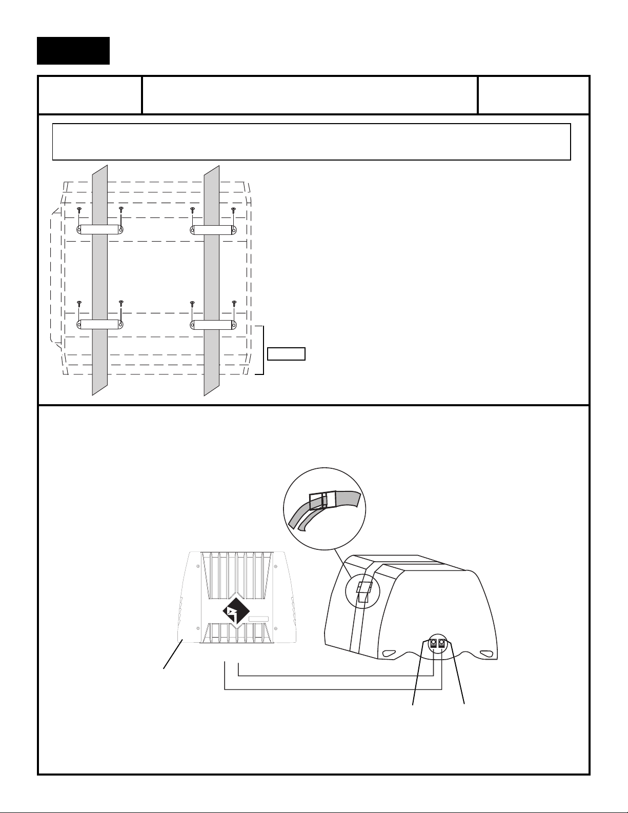
1. INSTALACIÓN DE LOS SOPORTES DE ANCLAJE
Coloque el recinto en la posición deseada y posicione los soportes de anclaje
aproximadamente a 10cm hacia el interior de los finales del recinto. Júntelos lo mas
posible ei recinto sin mover el mismo. Cuidadosamente quite el recinto y fije los
soportes usando los tornillos que se le han suministrado.
NOTA: Preste atención donde atornilla los soportes. Evite paneles de plástico y
cartón piedra. Sik lo hiciera los tornillos podrian arrancarse por la vibración de la
carretera o durante una frendad brusca.
ATENCIÓN: Antes de taladrar revise debajo del vehiculo para prevenir
daños en las conducciones de frenos o carburante.
5-8cm
2. INSTALACIÓN DE LAS BRIDAS DE MONTAJE
Asegure los angulos de montaje y posicione el tubo en el lugar deseado (sobre los angulos) estire las bridas y asegurelas.
NOTA: Asegurese de que las bridas pasan por el bucle correctamente. Verifique regularmente que el tubo este fijamente asegurado.
–
+
Amplificadore
puente (4Ω)
Negro
Rojo
3. RECORRIDO DEL CABLE DE ALTAVOZ DESDE EL AMPLIFICADOR
Al llevar el cable de altavoz desde el amplificador, evite que pase cerca de cualquier fuente de alto corriente (cables de alimentacion). El terminal
positive (+) de las salida de rojo del tubo, y el terminal negativo (–) al terminal negro.
– 3 –
Page 5

FRANÇAIS
RFT-1081
RFT-1101
ATTENTION: Veuillez suivre ces instructions. Ne pas les suivre ou ne pas installer correctement le caisson pourrait
causer des dégâts ou de sérieuses blessures, en cas d’accident.
8” Box That Rocks
10” Box That Rocks
1. INSTALLATION DES LANIÈRES DE MONTAGE
Placez le caissons dans l’emplacement désiré et mettez-les crochets à environ 10cm
avant chaque extrémité de celui-ci. Retirez doucement le caisson et fixer les crochets
avec les vis fournies aussi prés que possible du caisson sans le bouger ou le soulever.
ATTENTION: Avant de percer, assurez-vous de ne pas endommager les
organes vitaux du véhicule (conduit de freinage, d’essence, etc.)
5-8cm
d’Installation
Schéma
2. INSTALLATION DES LANIÈRES DE MONTAGE
Passez chaque lanière dans le paire de crochets de montage et positionner le caisson a sa place. Serrez bien chaque lanière.
ATTENTION: Veuillez à ce que chaque lanière de montage soit correctement passée dans la boucle. Contrôlez régulièrement les boucles afin que
le caisson reste solidement mis en place.
–
+
Amplificateur
ponté mono 4Ω
Noir
3. BRANCEMENT DU CÂBLE HAUT-PARLEUR DE L’AMPLIFICATEUR
En plaçant le câble haut-parleur provenant de l’amplificateur, éviter son cheminement à proximité d’une source de courant importante. La sortie positive
de l’amplificateur se connecte sur le bornier rouge du caisson, le négatif se branche sur le bornier noir.
Rouge
– 4 –
Page 6
DEUTSCH
RFT-1081
RFT-1101
8” Box That Rocks
10” Box That Rocks
Installations
Beiblatt
WARNUNG: Bitte lesen Sie diese Gebrauchsanweisung zuerst sorgfältig durch. Dies verhindert den falschen Einbau des
Gehäuses und damit evtl. Garantieausfälle.
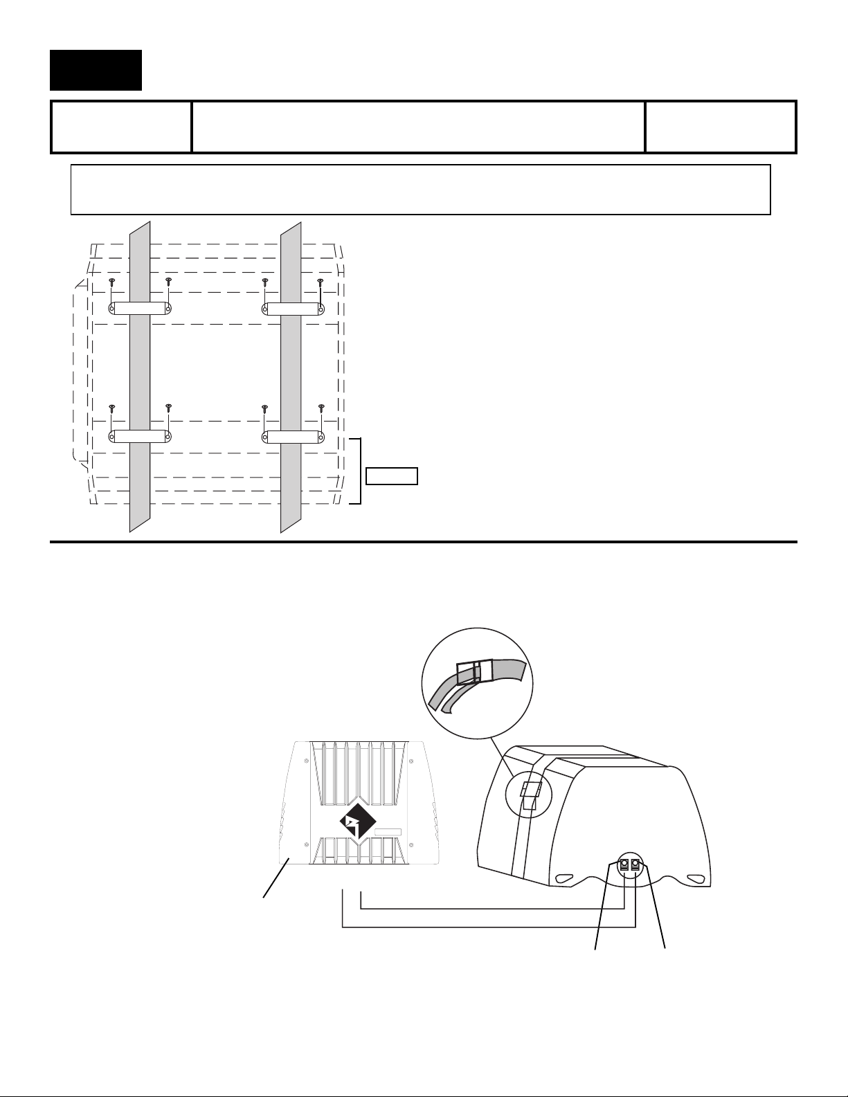
1. EINBAU DER BEFESTIGUNGSPUNKTE
Plazieren Sie das Gehäuse an dem ausgesuchten Platz. Kennzeichnen Sie nun die
Punkte, an denen die Befestigungsösen festgeschraubt werden sollen. Ca 10 cm von
jedem Ende des Gehäuses zur Gehäusemitte hin. Schrauben Sie dann vorsichtig mit
den dafür vorgesehenen Schrauben die Ösen am Gehäuse fest
ACHTUNG: Befestigen Sie das Gehäuse nicht an Plastik oder leicht zerbrechlichen
Teilen, die beim Festzurren beschädigt werden könnten. Das Gehäuse muβ so fest
wie möglich gezogen werden, um Vibrationen zu vermeiden.
WICHTIG: Achten Sie vor dem Bohren darauf, daβ Fahrzeuggegenstände wie
Benzinleitungen, Tank oder ähnliches beschädigt werder können.
5-8cm
2. EINBAU DER BEFESTIGUNGSBÄNDER
Ziehen Sie die Bänder durch die Befestigungsösen und plazieren Sie das Gehäuse an dem dafür vorgesehenen Ort. Ziehen Sie nun die Bänder fest.
ACHTUNG: Achten Sie darauf, daβ die Bänder richtig durch die Ösen geführt wurden. Kontrollieren Sie die Bänder, ob das Gehäuse richtig fest und
am richtigen Ort sitzt.
–
+
Verstärker 4Ω
mono
Schwarz
Rot
3. ANSCHLUβ DES LAUTSPRECHERKABELS
Beim Anschluβ des Lautsprecherkabels sollten Sie darauf achten, daβ das Kabel keine stromführenden Kabel kreuzt, um Einstreuungen zu verhindern.
Die Plus-Leitung des Lautsprecherkabels kommt in die rote Klemme des Terminals, die Negativ-Leitung in die schwarze Klemme es Terminals.
– 5 –
Page 7
ITALIANO
RFT-1081
RFT-1101
8” Box That Rocks
10” Box That Rocks
Istruzinoni di
Installazione
ATTENZIONE: Si prega di seguire attentamente queste istruzioni. Non farlo o non fissare in modo corretto il diffusore
potrebbe risultare dannoso per le persone e per l’apparecchio.
1. MONTARE I FISSANTI
Posizionare il diffusore nella zona desiderata e posizionare le staffe di fissaggio a
circa 10 cm dalle estremitá. Spingere le staffe il piú vicino possibile al diffusore senza
muoverlo o sollevarlo. Togliere con cura il diffusore e fissare le staffe con le viti a
dotazione.
NB: Attenzione a non fissare il idffusore su pannelli in cartone o plastic.
Facendolo le viti potrebbero essere spinte fuori dal pannello a causa di vibrazioni
alla guida o improvvise frenate.
ATTENZIONE: Prima di trapanare controllare sotto il veicolo per evitare di
danneggiare l’impianto di frenata, I condotti di carburante, ecc.
5-8cm
2. MONTARE LE CINGHIE
Far passare le due cinghie attraverso le staffe di fissaggio e riposizionare il diffusore nella posizione prescelta tra le staffe (sopra le cinghie). Singere bene le cinghie.
NB: Assicurarsi che le cinghie siano correttamente passate nelle fibbie. Controllare le cinghie periodicamente per assicurarsi che il diffusore sia saldamente
fissato al suo posto.
–
+
Amplificatore 4Ω
mono
Nero
Rosso
3. FAR CORRERE IL CAVO DELL’ALTOPARLANTE ALL’AMPLIFICATORE
Quando fate correre il cavo dell’altoparlante all’amplificatore non fatelo passare vicino a qualsiasi cavo dell’impianto elettrico di serie dell’auto. Il
segnale positivo dell’altoparlante (+) in uscita dall’amplificatore éz collegato al terminal rosso del diffusore, e il negativo (–) al terminale nero.
– 6 –
Page 8

L
IMITED
Rockford Corporation offers a limited warranty on Rockford Fosgate products on the following terms:
• Length of Warranty
3 years on electronics 90 days on electronic B-stock (receipt required)
2 years on source units 30 days on speaker B-stock (receipt required)
• What is Covered
This warranty applies only to Rockford Fosgate products sold to consumers by Authorized Rockford Fosgate Dealers in the United States
of America or its possessions. Product purchased by consumers from an Authorized Rockford Fosgate Dealer in another country are covered
only by that country’s Distributor and not by Rockford Corporation.
• Who is Covered
This warranty covers only the original purchaser of Rockford product purchased from an Authorized Rockford Fosgate Dealer in the United
States. In order to receive service, the purchaser must provide Rockford with a copy of the receipt stating the customer name, dealer name,
product purchased and date of purchase.
• Products found to be defective during the warranty period will be repaired or replaced (with a product deemed to be equivalent) at
Rockford's discretion.
• What is Not Covered
1. Damage caused by accident, abuse, improper operations, water, theft
2. Any cost or expense related to the removal or reinstallation of product
3. Service performed by anyone other than Rockford or an Authorized Rockford Fosgate Service Center
4. Any product which has had the serial number defaced, altered, or removed
5. Subsequent damage to other components.
6. Any product purchased outside the U.S.
7. Any product not purchased from an Authorized Rockford Fosgate Dealer
W
ARRANTY
I
NFORMATION
• Limit on Implied Warranties
Any implied warranties including warranties of fitness for use and merchantability are limited in duration to the period of the express warranty
set forth above. Some states do not allow limitations on the length of an implied warranty, so this limitation may not apply. No person is
authorized to assume for Rockford Fosgate any other liability in connection with the sale of the product.
• How to Obtain Service
Please call 1-800-669-9899 for Rockford Customer Service. You must obtain an RA# (Return Authorization number) to return any product
to Rockford Fosgate. You are responsible for shipment of product to Rockford.
Ship to: Electronics
Rockford Corporation
Warranty Repair Department
2055 E. 5th Street
Tempe, AZ 85281
RA#:_________________
Ship to: Speakers
Rockford Acoustic Design
(Receiving-speakers)
609 Myrtle N.W.
Grand Rapids, MI 49504
RA#:_________________
MADE IN THE USA
This product is designed, developed and assembled in the USA by a dedicated group of
American workers. The majority of the components used in the construction of this product
are produced by American companies. However, due to the global nature of their
manufacturing facilities and the electronics parts industry in general, some parts may be
LIT9709
2/98
manufactured in other countries.
Rockford Fosgate
Rockford Corporation
546 South Rockford Drive
Tempe, Arizona 85281 U.S.A.
In U.S.A., (602) 967-3565
In Europe, Fax (49) 850-3934-014
In Japan, Fax (81) 559-79-1265
 Loading...