

Page 1

Email:[email protected]
Http://www.motionrc.com
Page 2
Multipurpose Glider
OPERATING MANUAL
Page 3
WARNING
Read th e ENTIRE instruction manual t o become familiar wi th the fe atures of the prod uct WARNIN G:
!
before operating. Failure to operate the product correctly can result in damage to the product, personal
property an d cause serious injury.
Th is is a sophisticated hob by product and NOT a to y. It must be operated wit h caution and common sens e
and requires some basic mechanical ability. Failure to operate this Product in a safe and responsible manner
could result i n injur y or da mage to t he prod uct or ot her pro perty. Thi s product is not intend ed for us e by
children wi thout direct adult supervisio n.
This manual contains instru ctions for safety, operati on a nd m aintenance. It is essential to read and f ol lo w
all the i ns tructions a nd warnings i n manual, p ri or to assem bl y, setup or us e, in order to operate c orrectly
an d av oi d damage or serious injury.
Safety Precautions and Warnings
As the user o f this product, y ou are solely r es ponsible for op er ating in a ma nn er that does no t endanger
yourself and ot he rs or result in damage to th e product or th e property of oth er s. This model is co ntrolled
by a radio si gn al subject to i nt erference from many sources ou ts ide your contro l. This interfe re nce can
cause momentary l oss of control so it is advisable to a lways ke ep a safe dista nc e in all directio ns
your model, as this margin wil l help avoid co ll isions or injur y.
Age Recommendation: Not for children under 14y ears. This is not a toy.
• Never operate your model with low transmitter ba tteries.
•Always operate your mode l in an open area away from cars, traff ic or people.
• Avoid oper ating your model in the street where injury or damag e can occur.
• Never operate the model in t he street or in populated areas for any reason.
• Carefully fo llo w the di rec tio ns and w arn ing s f or th is and any opt ion al sup port equ ipm ent (c har gers,
rechargeable battery p acks, etc.) you use.
• Keep all chemicals, smal l parts and anything electrical out of the reach of children.
• Moisture causes damage t o electronics. Avoid water exposure to all equipment not specifically designed
and protected for this purpose.
• Never lick or place any port ion of your model in your mouth as it could cause seriou s injury or even death.
around
ROCHOBBY Friendly Reminder
Thank you for purchasing a RocHobby product.
Our goal is to provide high quality products and
offer great customer service. If you have any
problems with your product or want to offer
suggestions for improvements (such as plane
design, packaging, building instructions, etc.)
please feel free to contact us at
page1
For More Info Vist: www.motionrc.com
Page 4
step1
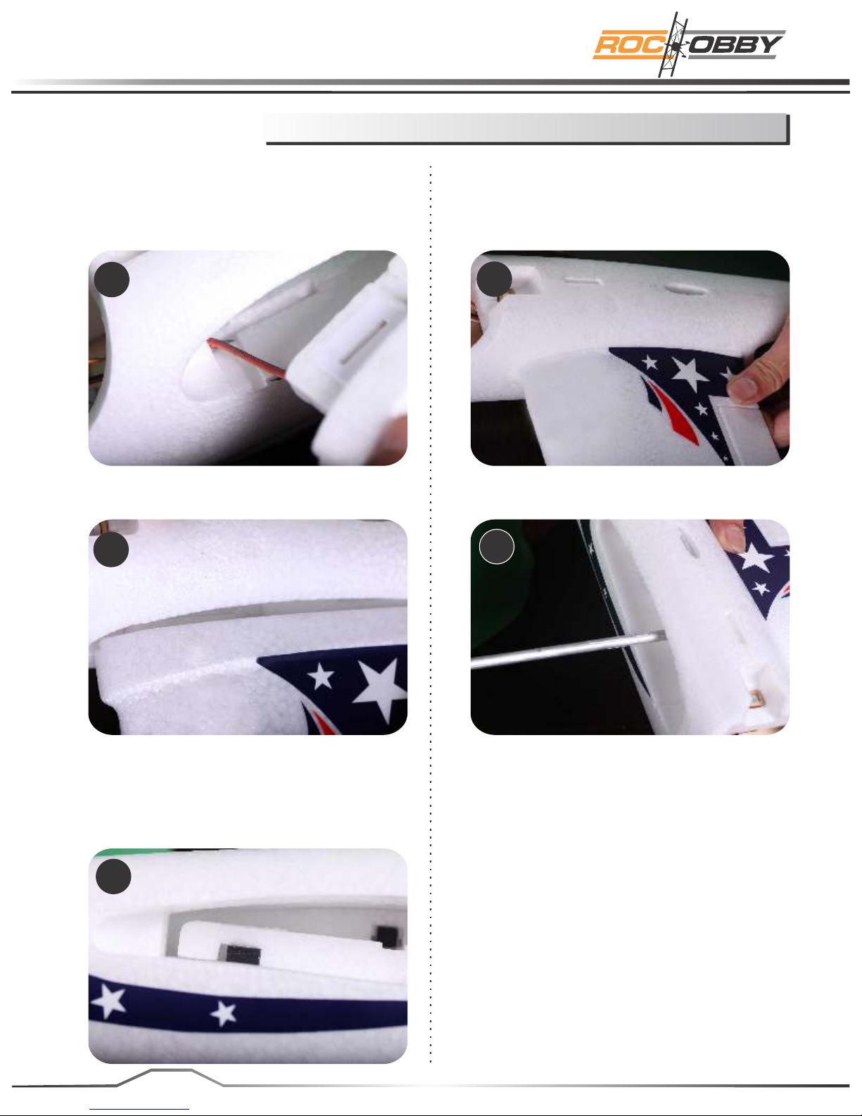
Fix the main wing to the fuselage
1. Install the left main wing.
First, guide the aileron servo cable through
the hole in front of the fuselage wing
mounting slot.
1
2. Now insert the left main wing slowly into
the slot.
2
4. Slide in the left main wing util it is fully
seated into the slot as shown in the
picture.
4
5. Insert the aluminum wing spar through the
fuselage and into the socket on the left wing.
5
3. Make sure the socket for the back
loading thrust (top mounted prop) does
not obstruct the entry of the wing. If
necessary, press the socket gently to
allow the wing to fully seat in the slot.
3
page2
Page 5
Fix the main wing to the fuselage
step1
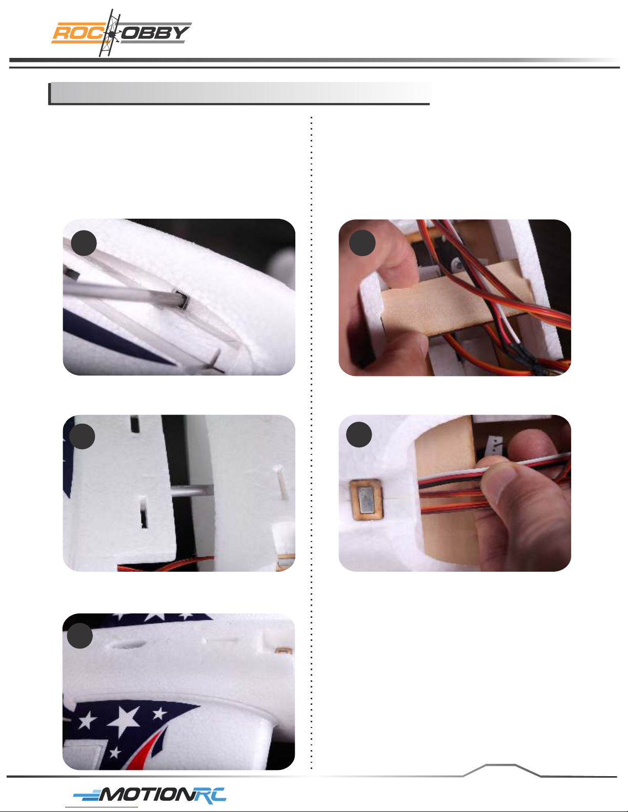
6. When sliding the wing spar into the wing,
it should go in easily. DO NOT force
it or push it beyond the point when you feel
minor resistance. If the spar is inserted
too far it will damage the foam and prevent
the opposite wing from fully engaging
the wing spar.
6
7. Mount the right main wing half onto the
aluminum wing spar.
9. Slide in the laminated board along the
two pre-notched slots inside the battery
hatch.
The board can be used to keep the aileron
and back loading thrust motor extension
wires away from the arms of the servos.
9.1
7
8. Repeat the step 1,2&4 for the right main
wing half installation.
8
9.2
page3
For More Info Vist: www.motionrc.com
Page 6
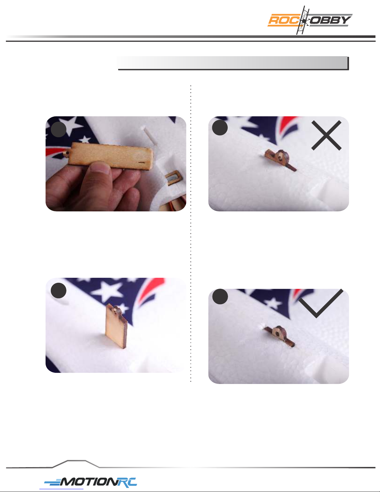
step1
Fix the main wing to the fuselage
10. Secure the main wing using the
pre-cut laminated board.
10
11. Insert the board into the leading slot on
top of the fuselage. NOTE: the top
side of the board is angled and will
align with the slope of the fuselage.
Make sure the two wing halves are fully
seated before the board is inserted.
12. This board is installed incorrectly.
12
13. This is board is correctly installed.
11
page4
13
For More Info Vist: www.motionrc.com
Page 7
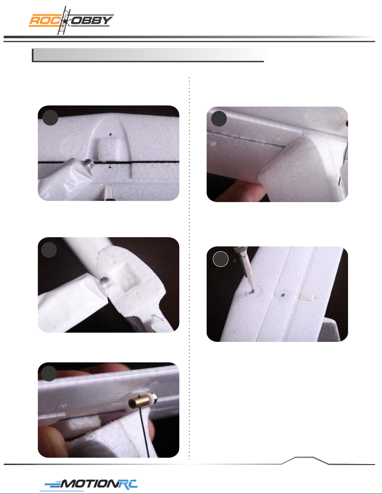
Installing the elevator
step2
1. Apply glue to the cutout area on the
on the bottom of the horizontal stabilizer.
Use a brush or hobby stick to thoroughly
cover the notch with a thin layer of glue.
1
2. Apply glue to the top of the rudder
where it will meet the horizontal
stabilizer.
2
4. Fit the horizontal stabilizer fully into
place, making sure there are no gaps.
4
5. Secure the stabilizer using the provided
screws. (Screw PB2.0*32)
5
3. Insert the pre installed linkage rod end
into the control connector on the elevator.
3
page5
For More Info Vist: www.motionrc.com
Page 8
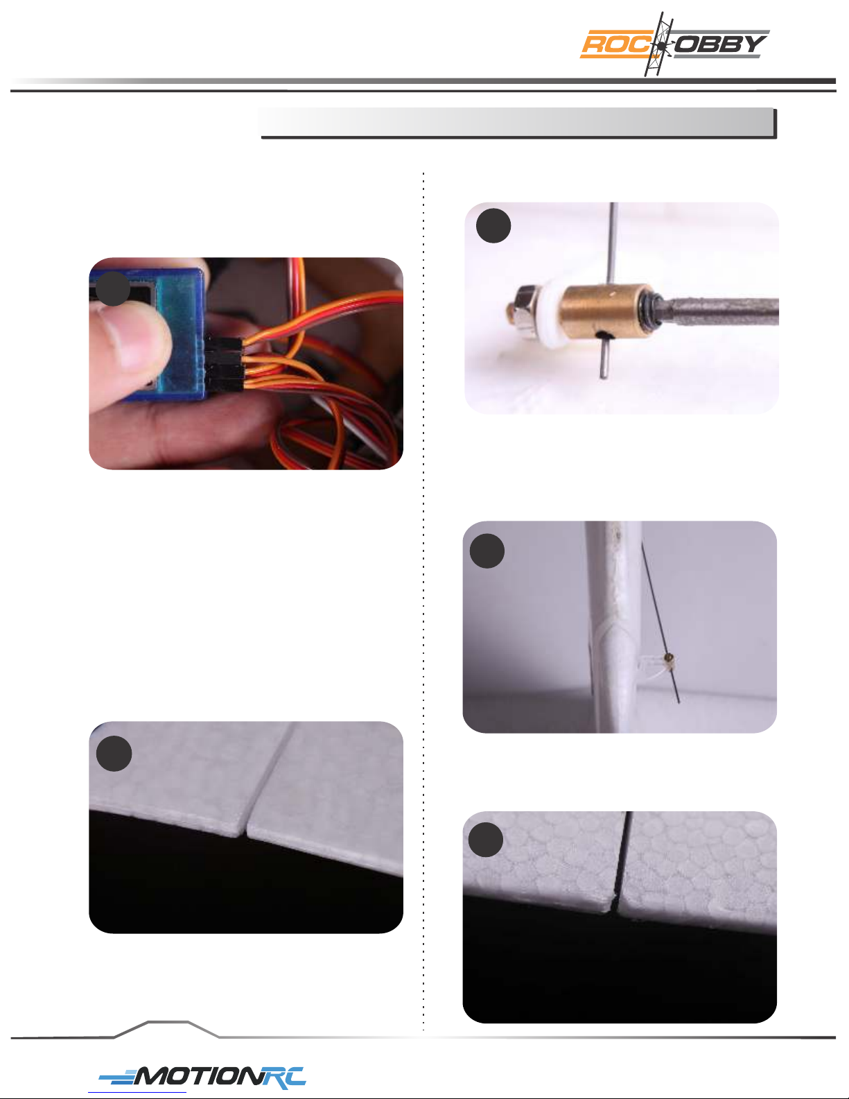
step3
Control surface Neutral Position setting
1. Connect the cables to the receiver.
NEVER arm the ESC before you turn on
the transmitter to avoid any property
or personal injury.
1
2. Please refer to your transmitter manual
before binding your receiver to your
transmitter.
Turn on the transmitter, make sure
no people or objects are in an unsafe
range of your propeller.
Adjust the elevator to be level with the
wing's trailing edge. Make sure the
elevator is well aligned as this will have
a direct impact on the plane's aerobatic
performance.
2.2 Secure the linkage rod by tighten
the hex screw in the control connector.
2.2
3. Make sure the rudder aligns with the
fuselage and repeat step 2 for the
control rod connection.
3
2.1
page 6
4. Repeat step 3 for the aileron control
horn connections.
4
For More Info Vist: www.motionrc.com
Page 9
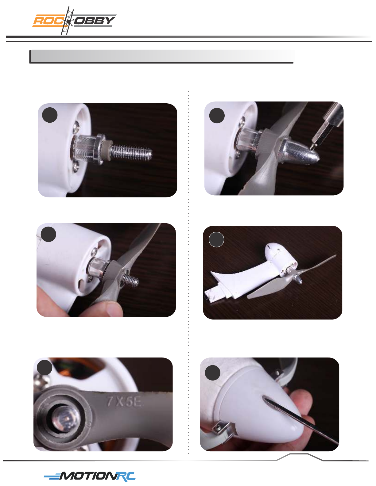
The back loading thrust alternative power setting
step4
1. Install the propeller adaptor as the
picture shows, making sure to install
the plastic collar on the adaptor shaft.
1
2. Install the propeller.
2
4. Secure the propeller using the spinner.
The spinner should be tight, but take care not
to over tighten which will damage the prop.
4
5. Verify the completed back loading thrust
assembly.
5
3. Make sure the side of the propeller with
the label 7X5E faces away from the
motor.
3
6. Use a screwdriver to remove two self
tapping screw securing the spinner
cone to the spinner backplate.
6
page 7
For More Info Vist: www.motionrc.com
Page 10
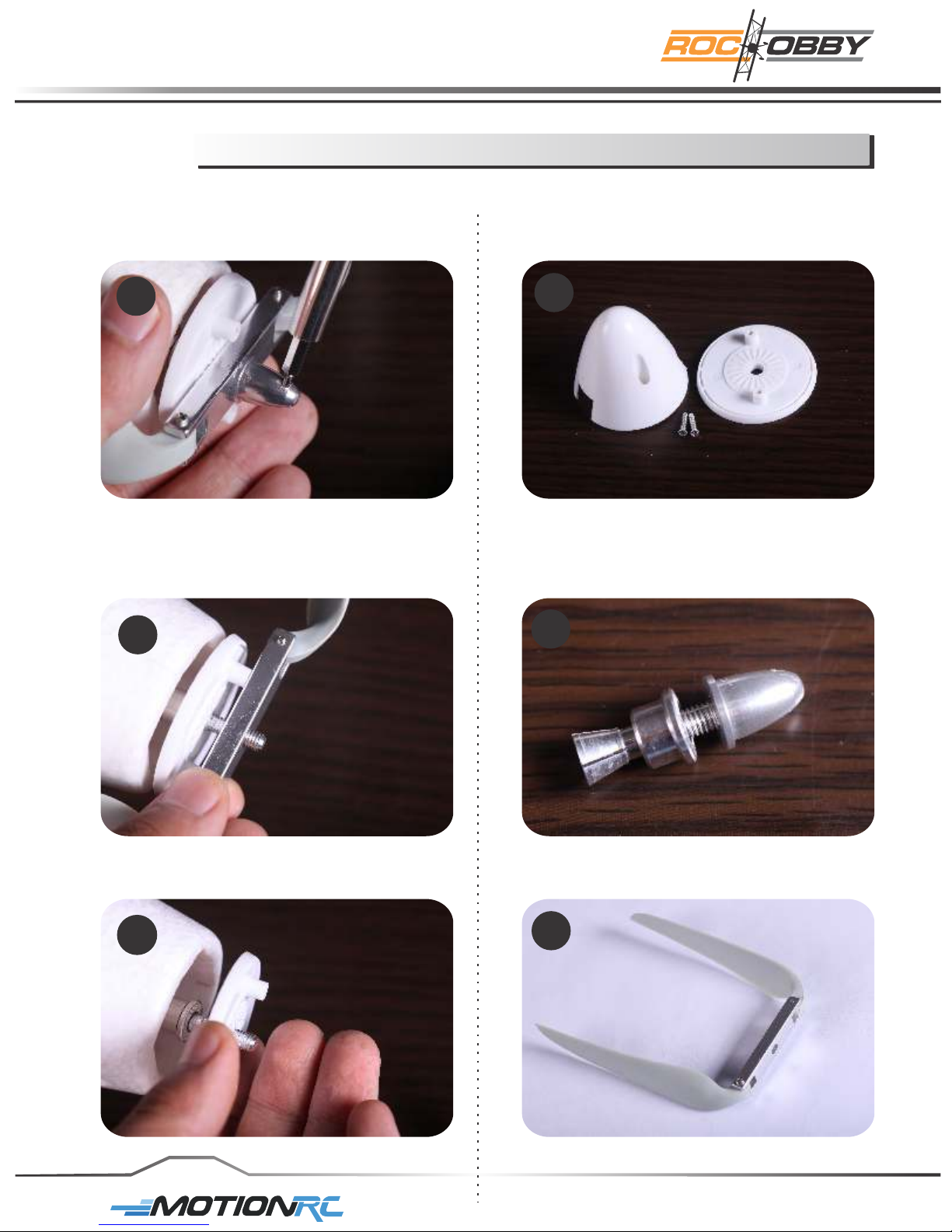
step4
The back loading thrust alternative power setting
7. Remove the propeller nut from the
motor adaptor.
7
8. Remove the propeller from the motor
adaptor.
8
9.2
9.3
9. remove the propeller backplate.
9.1
page 8
9.4
For More Info Vist: www.motionrc.com
Page 11
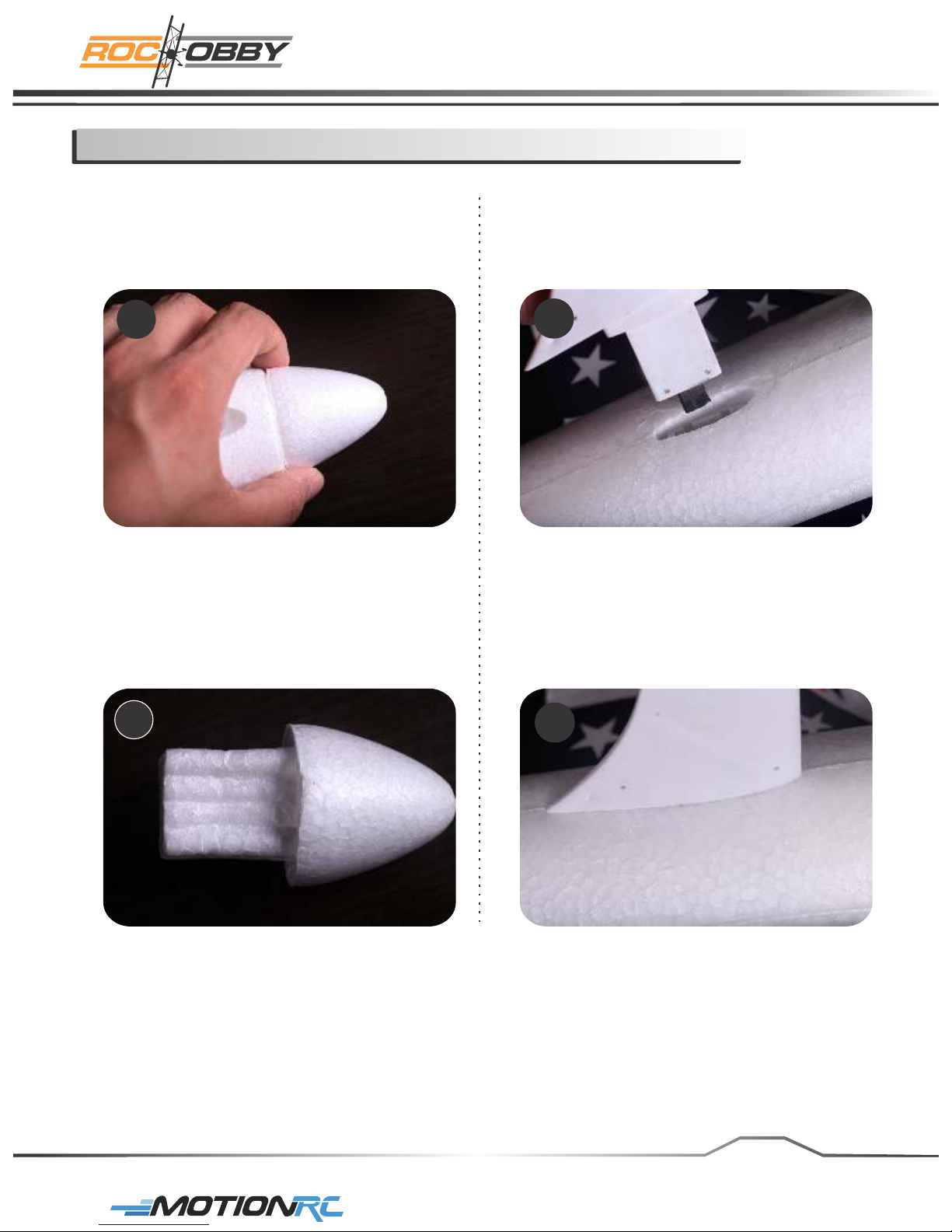
The back loading thrust alternative power setting
step4
10. Attach the foam nose to the front of the
fuselage.
10.1
11. Mount the back loading thrust assembly
to the fuselage with the propeller toward
the front of the airplane.
11
12. Make sure the motor mount is completely
inserted into the slot. There should be no
gap between the fuselage and the motor
mount. Improper assembly may prevent
the motor from working properly.
10.2
12
page9
For More Info Vist: www.motionrc.com
Page 12
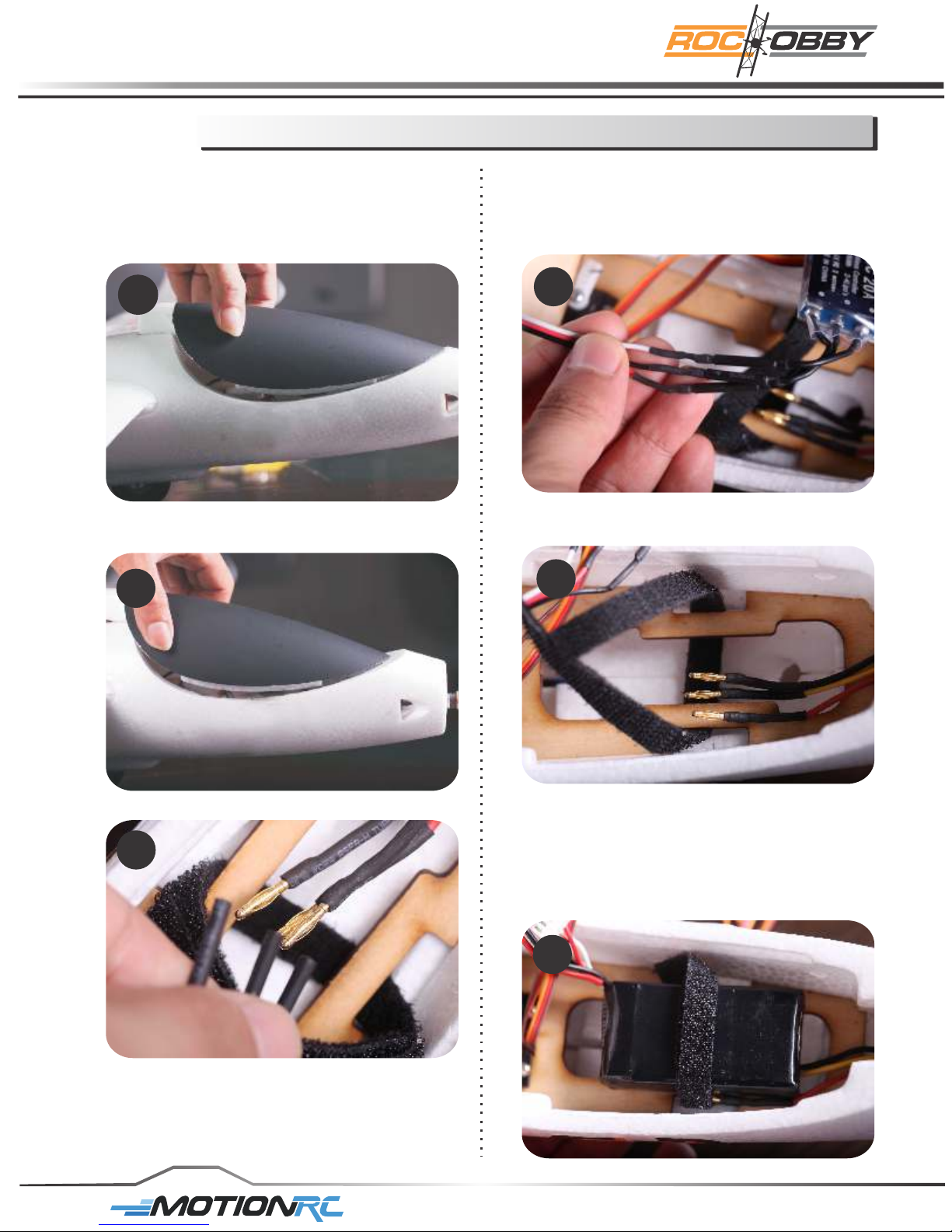
step4
The back loading thrust alternative power setting
13. Remove the canopy hatch from the
fuselage by lifting the hatch at the rear .
The canopy attaches with a magnet at
the rear and a laminated latch at the
front.
13
14. Slide the canopy towards the back of
the plane to take the canopy off.
14
16. Connect the ESC to the back motor,
and test the motor to make sure it is
rotating in the correct direction. To reverse
direction simply switch any two leads.
16
17. Battery tray.
17
15. Disconnect the ESC from the head motor.
15
Note: When you change your glider from
front propeller to top mounted propeller
you will need to adjust the Center of
Gravity (CG). Please see Center of
Gravity section in this manual for more
details.
page10
18. Locate the motor battery.
We recommend the battery be charged
before it is installed.
Slide the battery under the hook and
loop strap. Secure the battery in the
fuselage using the strap.
18
For More Info Vist: www.motionrc.com
Page 13

Power configurations
1. Multiple purpose front motor & propeller
1 PC Head motor
1 PC ESC
1 PC Battery
4 PCS Servo
Tx&Rx
2. Multiple purpose back loading thrust (top mount)
1 PC fuselage back motor
1 PC Head motor (the head / front motor stays in place
at all times for proper CG)
1 PC ESC
1 PC Battery
4 PCS Servo
Tx&Rx
3. Multiple purpose unpowered glider
1 PC Head motor (For balancing the plane out,
without the power inlet)
1 PC ESC
1 PC Battery
4 PCS Servo
Tx&Rx
Note: When you change the configuration of your
Multi-Purpose Glider you will need to adjust the
placement of your battery to achieve the correct center
of gravity. Please make sure that you use the
recommended battery size and weight to achieve
the proper CG.
page 11
For More Info Vist: www.motionrc.com
Page 14
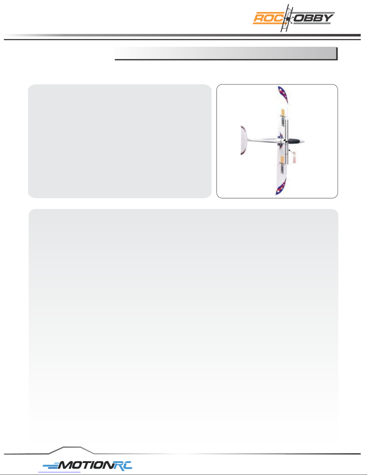
Main specification
Specification
Wingspan
Length
Weight
CG Position
Battery
ESC
Motor
Wing Area
Wing Load
RC System
Center of Gravity
When balancing your model, adjust the motor battery as necessary so the model is level or
slightly nose down.
This is the correct balance point for your model.
After the first flights, the CG position can be adjusted for your personal preference.
1. The recommended Center of Gravity(CG) location for your model is (42 to 50mm)
back from the leading edge of the top main wing as shown with the battery pack installed.
Mark the location of the CG on top of the wing.
2. When balancing your model, support the plane inverted at the marks made on the top
of the main wing with your fingers or a commercially available balancing stand. This is
the correct balance point for your model, Make sure the model is assembled and ready
for flight before balancing.
Note: Always balance the plane with the retracts down.
Control throw setting
1. Turn on the transmitter and receiver of your model.
check the movement of the rudder using the transmitter.
When the stick is moved right, the rudder should also move right. Reverse the direction
of the servo at the transmitter if necessary.
2. Check the movement of the elevator with the radio system.
Moving the elevator stick toward the bottom of the transmitter makes the airplane
elevator move up.
3. Check the movement of the ailerons with the radio system, moving the aileron stick right
makes the right aileron move up and left aileron move down.
4. Use a ruler to adjust the throw of the elevator, aileron and rudder.
Adjust the position of the pushrod at the control horn and the transmitter to achieve the
following measurements when moving the sticks to the end point.
Note: Always disassemble the propeller set when binding the transmitter and testing the
control surfaces.
: 1600mm /63.0 in
: 930mm /36.6 in
: 650g /22.9 oz
: 42mm
: 11.1V 1100mAh Li-Po Battery
: 20A
: A2208-KV1300
: 24dm
: 36g/dm
: 4 Channel, 4 Servos
And 1 Brushless ESC
2
2
Center Of Gravity(C.G.)
page 12
For More Info Vist: www.motionrc.com
Page 15

Main specification
The suggested throws for the ROCHOBBY Multipurpose Glider are as follows:
Low rate High rate
Elevator - 10mm/0.4in up an down 15mm/0.6in up and down
Rudder - 8mm/0.3in left and right 12mm/0.5in left and right
Ailerons - 11mm/0.4in up and down 18mm/0.7in up and down
Spare Parts List
Item#
MG 101 Fuselage (With the wheels installed)
MG 102 Main Wing (A set of main wing)
MG 103 Horizontal Stabilizer
MG 104 Canopy (One piece foamy canopy)
MG 105 Foamy Nose
MG 106 Plastic Spinner
MG 107 Propeller 1 (For Back Loading motor)
MG 108 Propeller 2(For the head thrust motor)
MG 109 Propeller mount (For back propeller)
MG 110 Motor Shaft for Back Loading motor
MG 111 Motor Shaft for head thrust motor
MG 112 Motor Base
MG 113 Motor 1 (For Back Loading)
MG 114 Motor 2 (For Head Thrust)
MG 115 Battery (11.1V 1100mAh)
MG 116 Decal sheet
Description
page13
For More Info Vist: www.motionrc.com
Page 16
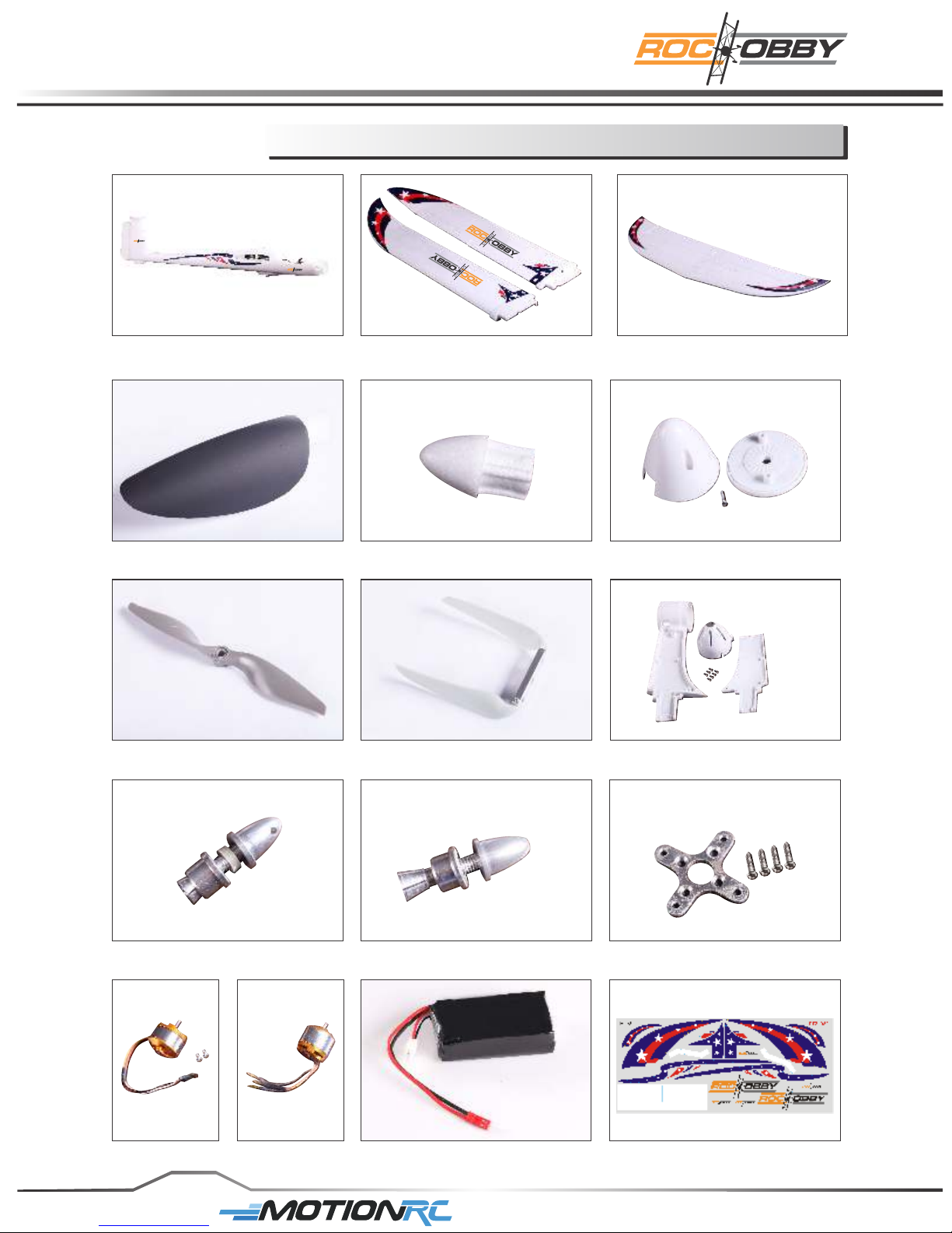
Spare Parts List
MG-101 MG-102 MG-103
MG-104
MG-107 MG-109
MG-105 MG-106
MG-108
MG-110 MG-111 MG-112
page 14
MG-115
For More Info Vist: www.motionrc.com
MG-116MG-113 MG-114
Page 17

Troubleshooting
Problem
Aircraft will not
respond to the
throttle but responds
to other controls.
Extra propeller noise
or extra Vibration.
Reduced flight time or
aircraft underpowered.
Control surface does
not move, or is slow to
respond to control
inputs.
Possible Cause Solution
ESC is not armed.
Throttle channel is reversed.
Damaged spinner, propeller.
motor or motor mount.
Loose propeller and spinner
parts.
Propellor installed backwards.
Flight battery charge is low.
Propeller installed backward.
Flight battery damaged.
Control surface, control horn,
linkage or servo damage, Wire
damaged or connections loose.
Lower throttle stick and throttle
trim to lowest settings.
Reverse throttle channel on
transmitter.
Replaced damaged parts.
Tighten parts for propeller
adapter, propeller and spinner.
Remove and install propeller
correctly.Completely recharge
Flight battery.
Remove and install propeller
correctly. Replace flight battery
and obey flight battery
instructions.
Replace or repair damaged
parts and adjust controls.
Do a check of connections for
loose wiring.
Control reversed.
Motor loses power.
Motor power pulses
then motor loses
power.
LED on receiver
flashes slowly.
Channels need to be reversed
in the transmitter.
Damage to motor, or battery.
Lose of power to aircraft.
ESC uses default soft Low
Voltage Cutoff(LVC).
Power loss to receiver.
Do the Control Direction Test
and adjust controls
for aircraft and transmitter.
Do a check of batteries,
transmitter, receiver, ESC,
motor and wiring for damage
(replace as needed).
Land aircraft immediately and
Recharge flight battery.
Check connection from ESC to
receiver.
Check servos for damage.
Check linkages for binding.
Battery Selection and Installation.
1. We recommend the 11.1V 1100mAh 15C Li-Po battery.
2. If using another battery, the battery must be at least a 11.1V 1100mAh 15C battery.
3. Your bat tery sho uld be appro ximat ely the same cap acity ,d imens ion and weig ht a s t he
11.1V 1100mAh 15C Li-Po battery to fit in the fuselage without changing the center of gravity
page 15
For More Info Vist: www.motionrc.com
Page 18

Flying Tips
Range Check Your Radio System
After final assembly, range check the radio system with the ROCHOBBY Multipurpose Glider.
Refer to your specific transmitter instruction manual for range test information.
Take off and landing tips
1. Take off using full power.
2. Ensure that you set a timer and land with plenty of battery power in reserve.
3. Never exceed 3 minutes of full power flight.
4. Never exceed the limited flying weight.
First Flight Preparation
1. Remove and inspect contents.
2. Charge fl ight battery
3. Read this instruction manual thoroughly
4. Fully assemble model
5. Install the flight battery in the aircraft ( once it has been fully charged )
6. Bind aircraft to your transmitter
7. Make sure linkages move freely
8. Make sure the rubber ring has been properly slid on the clevises.
9. Perform the Control Direction Test with the transmitter.
10. Adjust flight controls and transmitter.
11. Perform a radio system Range Check.
12. Find a safe and open area.
.
.
.
.
.
.
Please read the following instructions and fully understand it.
1. Do not fly in strong wind or bad weather.
2. Never fly the model in crowded areas, where there are lots of people, automobiles on the
road or power lines overhead . Also do not fly around the airport. Please make enough
room for flying and operating your plane, as the plane can travel at high speed. Remember
you are responsible for the safety of others.
3. Children under the age of 12 should have an adult guide. This pl ane is NOT recommended
for chi ldren under the age o f 14.
4. Never leave the charger in wet conditions.
5. The Mu ltip urpo se Glid er is made fr om PA and po lyth ene whic h i s ti nder. Whe n i t
is exp osed to extreme heat, it may combus t, so keep aw ay from he at or open fl ames .
6. Do not attempt to catch the while flying, please do not touch the propeller. Multipurpose Glider
7. Never leave this system unattended around children with a battery in the unit, as injury may
be caused due to children's turning on the transmitter or the plane.
8. During the preparation for flight, please remember to turn on the transmitter before
connecting the battery pack.
9. Close the throttle on the transmitter before connecting battery otherwise the motor may operate.
For More Info Vist: www.motionrc.com
 Loading...