

Page 1

Email:[email protected]
Http://www.motionrc.com
Page 2
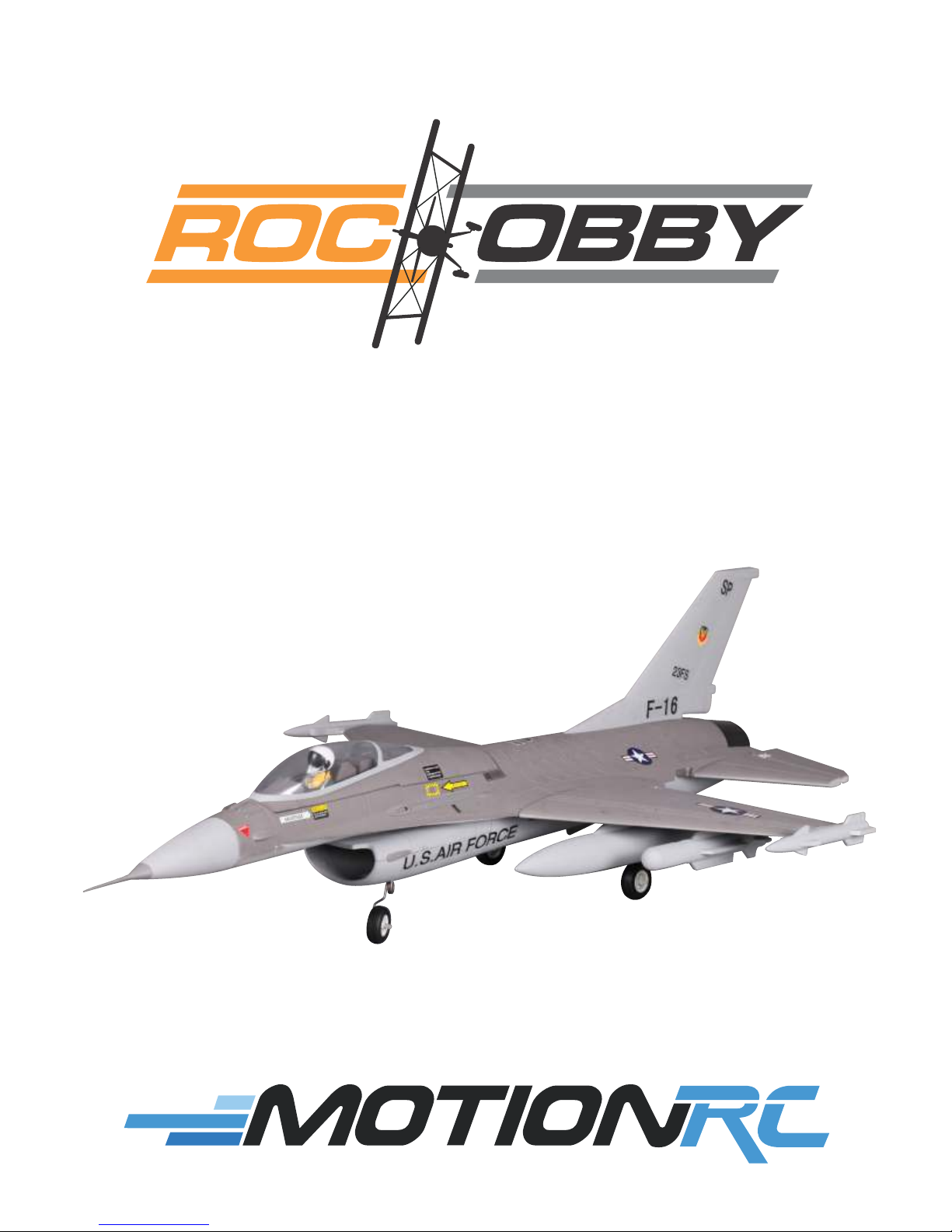
F-16 Falcon
OPERATING MANUAL
Page 3
WARNING!
Read th e ENTIRE instruction manual t o become familiar wi th the fe atures of the prod uct WARNIN G:
!
before operating. Failure to operate the product correctly can result in damage to the product, personal
property an d cause serious injury.
Th is is a sophisticated hob by product and NOT a to y. It must be operated wit h caution and common sens e
and requires some basic mechanical ability. Failure to operate this Product in a safe and responsible manner
could result i n injur y or da mage to t he prod uct or ot her pro perty. Thi s product is not intend ed for us e by
children wi thout direct adult supervisio n.
This manual contains instru ctions for safety, operati on a nd m aintenance. It is essential to read and f ol lo w
all the i ns tructions a nd warnings i n this manu al prior to a ssembly, setup , or use, in order to op er ate
correctly
Safety Precautions and Warnings
As the user o f this product, y ou are solely r es ponsible for op er ating in a ma nn er that does no t endanger
yourself and ot he rs or result in damage to th e product or th e property of oth er s. This model is co ntrolled
by a radio si gn al subject to i nt erference from many sources ou ts ide your contro l. This interfe re nce can
cause momentary l oss of control so it is advisable to a lways ke ep a safe dis ta nce in all direc ti ons
your model, as this margin wil l help avoid co ll isions or injur y.
Age Recommendation: Not for children under 14y ears. This is not a toy.
• Never operate your model with low transmitter ba tteries.
•Always operate your mode l in an open area away from cars, traff ic or people.
• Avoid oper ating your model in the street where injury or damag e can occur.
• Never operate the model in t he street or in populated areas for any reason.
• Carefully fo llo w the di rec tio ns and w arn ing s f or th is and any opt ion al sup port equ ipm ent (c har gers,
rechargeable battery p acks, etc.) you use.
• Keep all chemicals, smal l parts and anything electrical out of the reach of children.
• Moisture causes damage t o electronics. Avoid water exposure to all equipme nt not specifically designed
and protected for this purpose.
• Never lick or place any port ion of your model in your mouth as it could cause seriou s injury or even death.
an d av oi d damage or serious injury.
around
ROCHOBBY Friendly Reminder
Thank you for purchasing a RocHobby product.
Our goal is to provide high quality products and
offer great customer service. If you have any
problems with your product or want to offer
suggestions for improvements (such as plane
design, packaging, building instructions, etc.)
please feel free to contact us at
For More Info Vist: www.motionrc.com
Page 4

Table ofcontents
Kit contents 1
The spare parts list 1
Spare parts list content
The illustration of the spare parts
Kit Inspection 3
Charging the Flight Battery 3
Low Voltage Cutoff 6
Assemble the plane 6
Install the landing gear
Install the main wing
Install the horizontal stabilizer
Install the vertical fin
Install the nose cone
Install the ventral fin
Install the linkage rods
Install the battery
The receiver department
Check the C.G. (Center of Gravity)
Get your model ready to fly 14
Load the aircraft
Important ESC information
The transmitter and model setup
Check the control throws
Check the motor rotor direction
Before the model flying 18
Find a suitable flying site
Perform the range check of your plane
Monitor your flight time
Flying course 19
Take off
Flying
Landing
Maintenance
Troubleshooting 20
AMA 21
Page 5
Kit contents
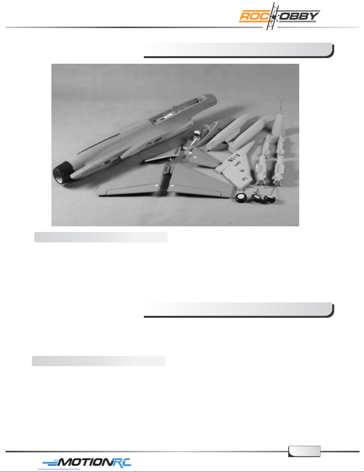
Kit contents
1. The fuselage assembly (With the fin, the canopy, the electronic parts, ESC)
2. Vertical stabilizer assembly
3. Horizontal stabilizer with the elevator hinged
4. Nose cone
5. Oil tanks and the Missiles
The spare parts list
ReplacementpartsfortheROCHobby F16 Falcon are available using the order numbers
in the Spare parts list that follows. The fastest, most economical service can be provided
by your hobby dealer or mail-order company.
Spare parts list content
Spare parts list content
KC 101 Fuselage (With all the plastic parts installed)
KC 102 Main wing set (With the control surface hinged)
KC 103 Horizontal stabilizer (With the control surface hinged)
KC 104 Vertical stabilizer
KC 105 Nose cone
KC 106 Canopy (With the foam cockpit and pilot)
KC 107 Ventral fin
KC 108 Fuel tanks
page1
For More Info Vist: www.motionrc.com
Page 6
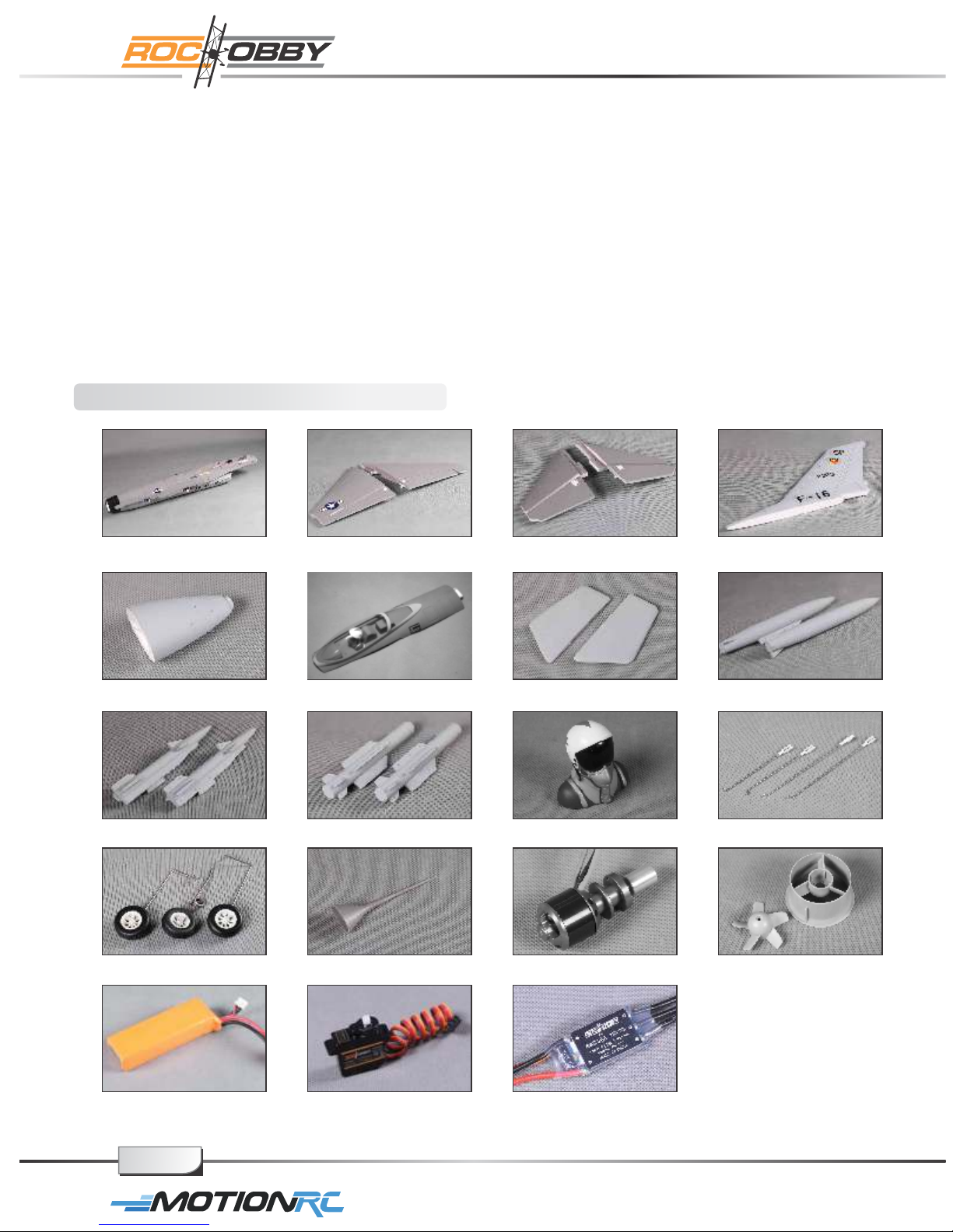
KC 109 Missile A (Wing tip loading)
KC 110 Missile B (Hang under the wing)
KC 111 Pilot
KC 112 Linkage rod (With the clevis and securing ring)
KC 113 Landing gear set (The main and the front landing gear)
KC 114 Air speed head
KC 115 Motor (2627 KV 4600)
KC 116 Ducted fan (64mm: The fan tube and the rotor)
KC 117 Battery (11.1V 1800mAh 25C)
KC 118 Servo (9g)
KC 119 ESC (35A with 4 A BEC)
The illustration of the spare parts
KC-101 KC-102 KC-103 KC-104
KC-105
KC-109
KC-113
KC-117 KC-118 KC-119
KC-106
KC-110
KC-114
KC-107
KC-111
KC-115
KC-108
KC-112
KC-116
page2
For More Info Vist: www.motionrc.com
Page 7
Kit inspection
Before starting to build, inspect the parts to make sure they are acceptable quality. If any
parts are missing or are not in good shape or acceptable quality, or if you need assistance
with setup and assembly, please feel free to contact Motion RC. Please write down the
name of the parts when you are reporting defective or missing of them.
Motion RC Product Support
ADDRESS: 28W039 Commercial Ave, Unit 8
Lake Barrington, IL 60010
Tel 224-633-9090:
Email: [email protected]
Web: www.motionrc.com
Charging the Flight Battery
The Battery Charger included with your aircraft is designed to safely charge the Li-Po battery,
Caution: All instructions and warnings must be followed exactly. Mishandling of Li-Po
batteries can result in fire, personal injury, or property damage.
Battery warning:
By handling, charging or using the included Li-Po battery
you assume all risks associated with lithium batteries.
If at any time the batteries begin to swell, or balloon, discontinue use immediately!
Charging or discharging a swelling or ballooning battery can result in fire.
Always store the batteries at room temperature in a dry area to extend the life of
the battery. Always transport or temporarily store the battery in a temperature range of
40-120 F. Do not store battery or model in a car or in direct sunlight. If stored in a hot car,
the battery can be damaged or even catch fire.
Never use a Ni-Mh charger. Failure to charge the battery with a compatible charger may
cause fire resulting in personal injury and property damage.
Never discharge Li-Po cells to below 3V.
Never leave charging batteries unattended.
Never charge damaged batteries.
Charging the flight battery
RTF kits come with a DC balancing charger. You must charge the battery with
a Li-Po specific charger only (such as the included BC-3S10 DC charger). When charging
the battery, make certain the battery is on a heat-resistent surface, charge the battery
before assembly of the airplane. Install the fully charged battery to perform control tests
and binding.
BC-3S10 Balance Charger
To correctly use the charger, please read the instructions before use.
o
page3
For More Info Vist: www.motionrc.com
Page 8
Charging the Flight Battery
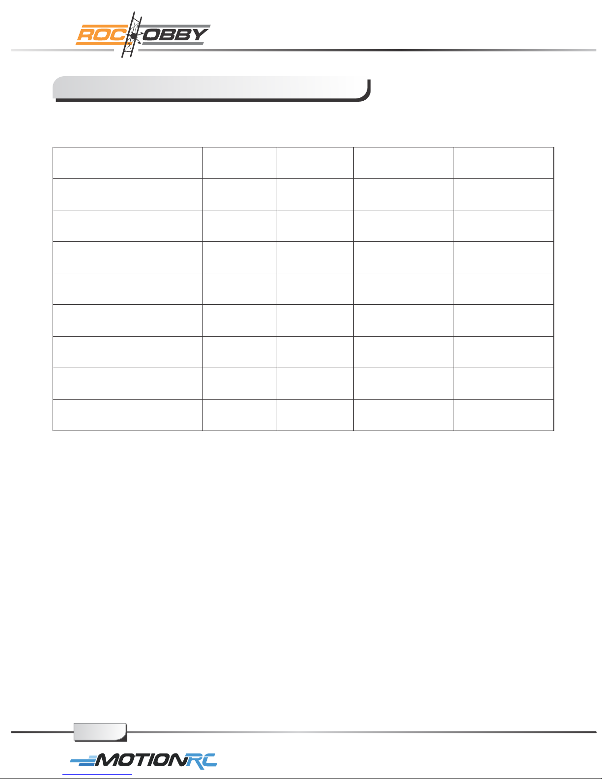
Electrical Parameters
Parameter
WorkingVoltage
InputPower
WorkTemperature
StoreTemperature
ChargingStopVoltage
ChargingCurrent
BalancingCurrent
ActivateCurrent
Min Type Max Unit
9
1 5 W
- 2 0
- 2 0
4 . 1 9
1 5 0
8 0 1 2 0
1 2
4 . 2 0
1 6
4 5
6 5
4 . 2 1 V
1 0 0 0
2 0 0
V
℃
℃
mA
mA
mA
page4
For More Info Vist: www.motionrc.com
Page 9

Charging the Flight Battery
Using Steps:
1. Connect the charger to adapter with enough voltage and wattage, then the Power LED will
turn on;
2. Connect 2S/3S battery pack to the corresponding balance port (Do not connect two battery
packs at the same time), then the Charge LED will flicker (1Hz) and start charging.
3. When the Charge LED stops flickering, charging is complete, and the batteries can be
unplugged.
Charging Function Description
1. If all voltage of the installed battery pack is higher than 4.18V, charging will not start and the
charge LED will shine.
2. If the voltage of one battery or some batteries is lower than 0.7V, charging will not start. If the
voltage of the first battery of a 3S battery pack is lower than 0.7V, the charger will charge the
battery pack as if it was a 2S battery pack.
3. If the voltage of one battery or some batteries is lower than 2.8V, the charger will activate the
battery pack with a small current. If the voltage can’t be increased above 2.8V after half an
hour, the charger will judge the battery pack as bad. The charge LED will then flicker rapidly
(0.5Hz), and charging will stop.
Self Checking Function
1. Charger will perform a self test before each charge. The charge LED will rapidly flicker (0.5Hz)
if the charging function is abnormal;
2. Accuracy checking Function: Connect a fully charged 3S battery pack (all voltage at least 4.2V),
the charge LED will flicker twice then shine always. This means that the accuracy is normal.
Protection Function
1. Reverse connection protection of input
2. Reverse connection protection of output
3. Short circuit protection of output
4. Over voltage protection of output
Troubleshooting
1. Power LED does not shine – Adapter isn’t connected correctly. Please check the polarity
and reconnect adapter.
2. Charging abruptly stops and tries to restart constantly during charging – Output power
of the adapter is not sufficient, please replace the adapter.
3. Charge LED does not shine – Reconnect the battery pack; Check the voltage of batteries.
4. Charge LED rapidly flickers – Battery is bad or charging function is abnormal. Replace
battery or contact technical support.
page5
For More Info Vist: www.motionrc.com
Page 10
Low voltage cut off (LVC)
WhenaLi-Poisdischarged below 3V per cell, it will not hold a charge. The ESC protects
the flight battery from over-discharge using Low Voltage Cutoff. Before the battery charge
decreases too much, LVC removes power from motor in two ways: (1) Reduces power ESC reduces motor power (recommended), (2) Hard cutoff - ESC instantly cuts motor
power when the pre-set Low Voltage Protection Threshold value is reached. These
settings can be changed using the ESC programing guide (available on-line).
Assemble the plane
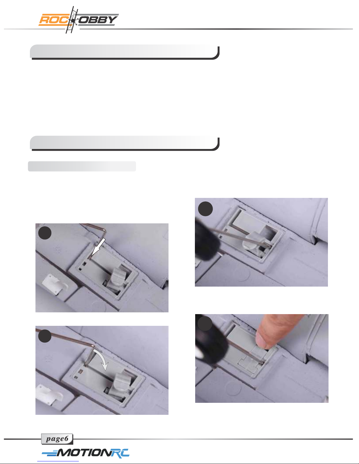
Install the landing gear
1. Slide L bend end of the landing gear
strut into the pre-notched slot on the
gear mounting base. Each strut should
installed so that the wheel faces
outwards when installed.
1.1
1.2
2. Rotate the strut as picture 1.2 shows
till the strut is fully seated into the slot.
2
3. Snap the plastic latch to secure the landing gear
into place.
3
page6
For More Info Vist: www.motionrc.com
Page 11
Assemble the plane
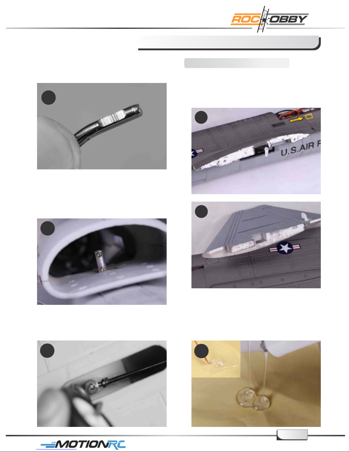
4. Install the front landing gear. The flat
spot of the strut will be used to hold the
strut firmly into place (step 6 below).
4
5. Check the socket inside the air intake to
ensure the screw side of the socket faces
the nose of the plane.
Install the main wing
1. Remove any paint (Tip - use strong
adhesive tape to easily remove paint)
where the main wing and the horizontal
stabilizer will fit together with the
fuselage.
1.1
1.2
5
6. Insert the front strut into the socket from
the bottom of the air intake with the flat spot
side toward the screws side of the socket.
6
2. Apply equal parts of quick dry epoxy into
the mixing plate and stir with a stick.
Note: Epoxy will dry in approx 3 to 5 min so
be sure you have adequate time to apply
glue and position parts.
2
page7
For More Info Vist: www.motionrc.com
Page 12
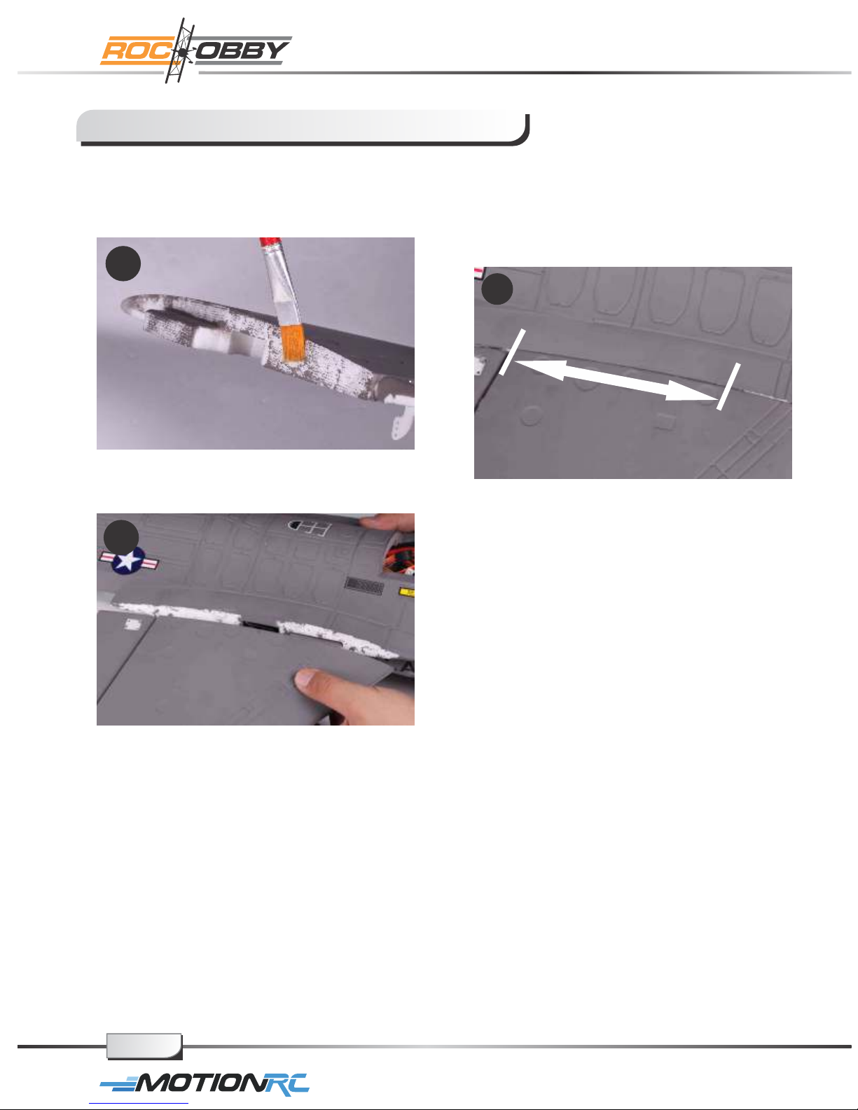
Assemble the plane
3. Apply the mixed epoxy to the starboard
wing and fuselage mating edge using
a brush or other applicator.
3
4. Fit the wing into place promptly (before
the epoxy begins to cure).
4
5. Make sure the top surface of the main
wing is level with the fuselage body.
Install the port side main wing following
the same method as steps 3 through 5.
5.1
page8
For More Info Vist: www.motionrc.com
Page 13
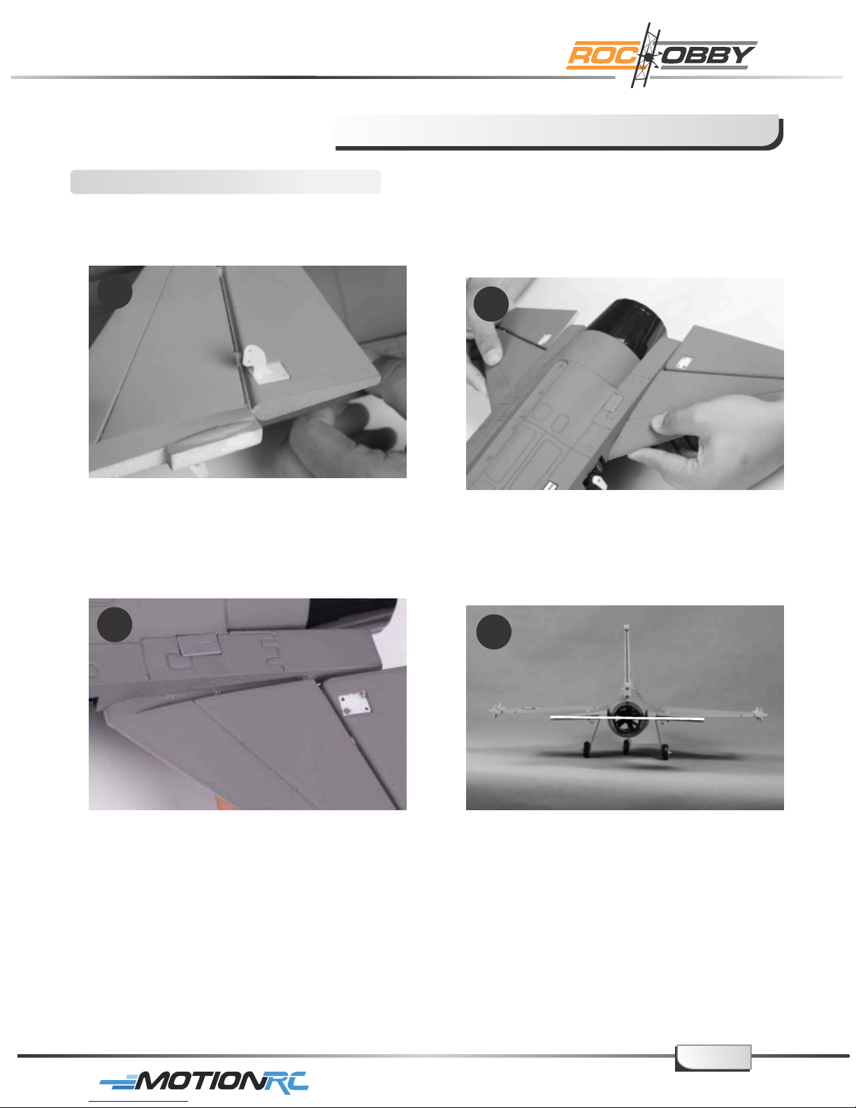
Install the horizontal stabilizer
Assemble the plane
1. Install the control horns on the bottom
side of the stabilizer as shown.
1
2. Glue the port side horizontal stabilizer
into place.
3. Fully seat the stabilizer into place,
make sure there is no gap left between
the stabilizer and the fuselage.
3
4. Make sure the stabilizer horizontal axis
is parallel to the wing as shown. Adjust
any misalignment before the glue dries
throughly.
2
4
page9
For More Info Vist: www.motionrc.com
Page 14
Assemble the plane
Install the vertical fin
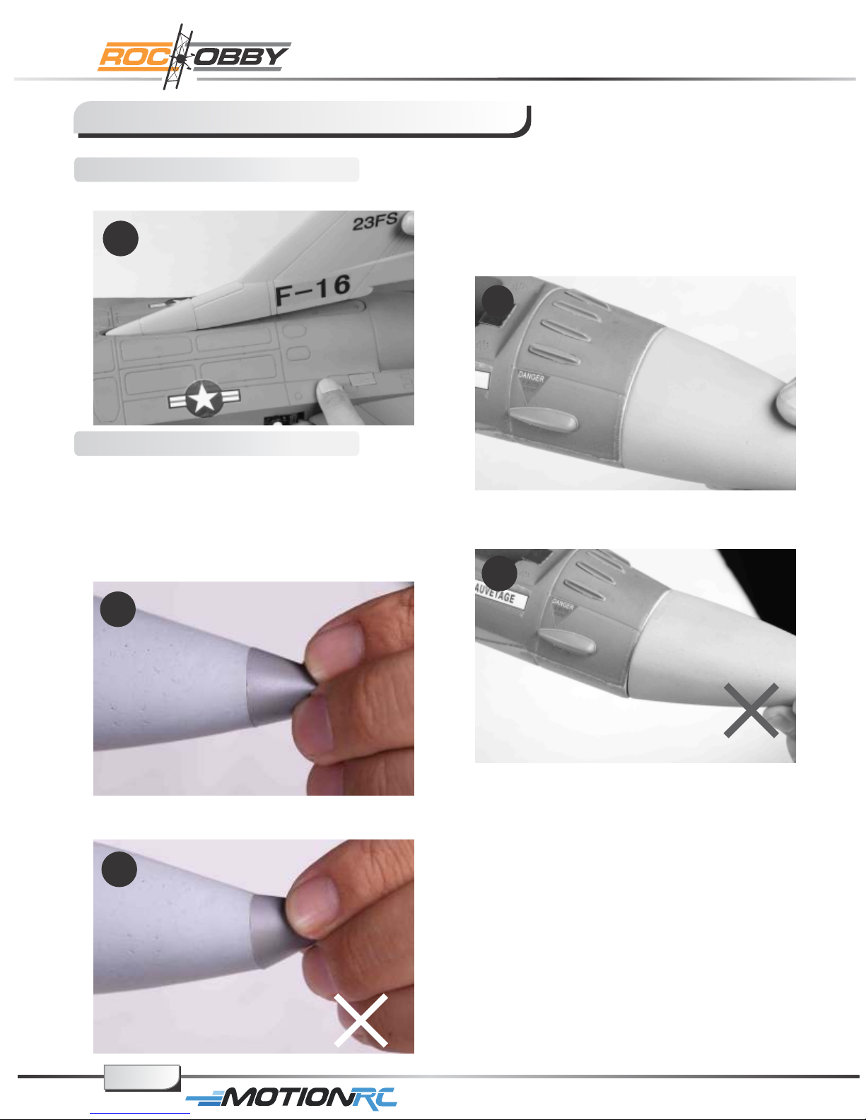
1. Glue the vertical stabilizer into place.
1
Install the nose cone
1. Glue the air speed head to the nose
cone. Ensure the air speed head and
nose cone are in perfect alignment.
Note: Use epoxy or other foam safe
adhesive when gluing to avoid damaging
the foam.
3. The nose cone is attached to the
fuselage using two pieces of magnets.
Figure 3 shows the right way to attach
the nose.
3
4. The wrong way to mount the nose cone.
4
1
2. The wrong way to mount the air speed
head.
2
page10
For More Info Vist: www.motionrc.com
Page 15
Assemble the plane
Install the ventral fin
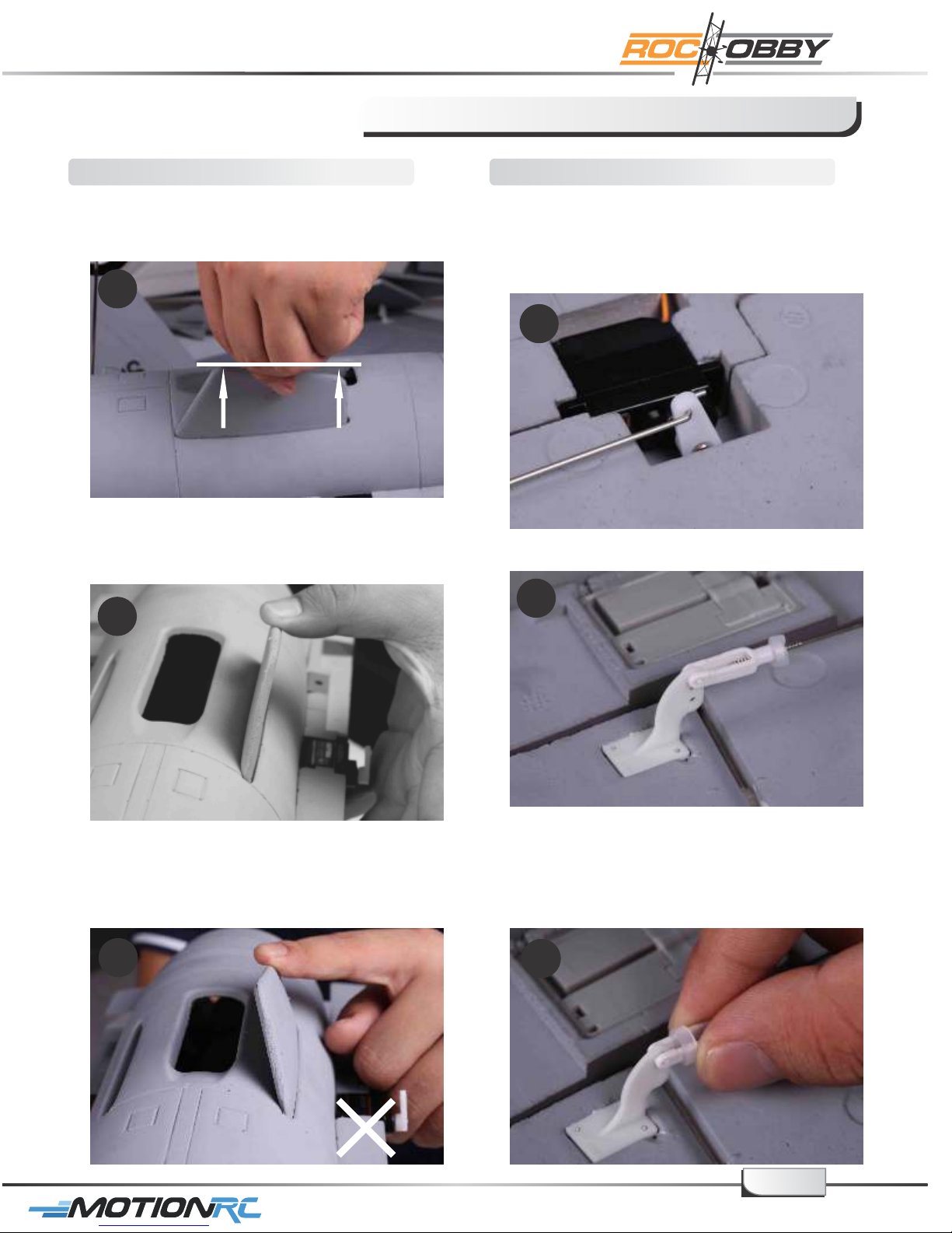
1. Fit one of the fins into place, the higher
side towards the front of the plane.
1
Higher
2. The fin will angle towards the outboard
of the plane as the picture shows.
2
Install the linkage rod
1. Put the Z-bend end of the linkage into
the desired servo control horn hole. It is
a tight fit and should allow the linkage to
move just slightly within the hole to avoid
binding up.
1
2. Snap the clevis into the surface control
horn.
2
3. This picture shows the WRONG way to
mount the fin. Glue the fin into place
after verifying the positioning is correct.
3
For More Info Vist: www.motionrc.com
3. The provided piece of fuel tubing keeps
the clevis closed during flight. Repeat
steps 1&2 for the remaining linkage rods.
Note: Do not over slide the securing
tube or it will impede the movement
of the surface control horn.
3
page11
Page 16
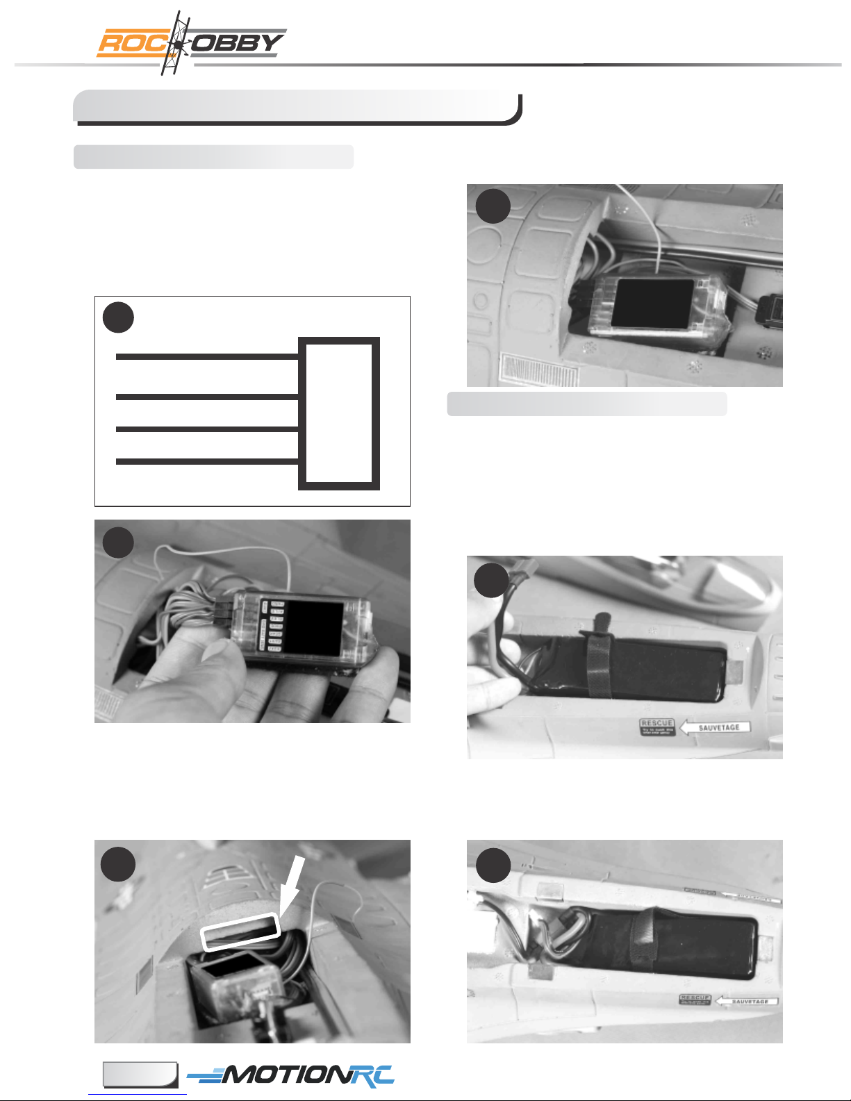
Assemble the plane
Installing the receiver
1. Attach aileron servo to the Aileron channel
of your receiver. Elevator harness goes to
elevator channel of your receiver. Steering
servo goes to the Rudder channel. Attach
the ESC connector
the throttle channel
t
o
of the receiver.
1.1
Aileron
Elevator
Throttle
Steering
1
2
3
4
Receiver
Channel-1
— Ail e
Channel-2
— Elev
Channel-3
— Thro
Channel-4
— Rudd
1.2
3. Mount the receiver into place and make sure
it will not impede the canopy mounting.
3
Install the battery
1. Slide the battery into the battery hatch
with the power supply cable toward the
rear end of the plane. Secure the battery
using the hook and loop strip.
Note: You may need to relocate the battery
position to achieve the correct CG for
your F16 model.
2. Tuck the wire leads into the recessed cavity
at the rear end of the canopy hatch.
Note: Keep wires clear from notched area
at the rear of the hatch (highlighted) to
ensure canopy stays secure in flight.
2
1
2. Fit the power connector into place and
make sure the power supply wire does
not interfere with the canopy’s closure.
2
page12
For More Info Vist: www.motionrc.com
Page 17
Assemble the plane
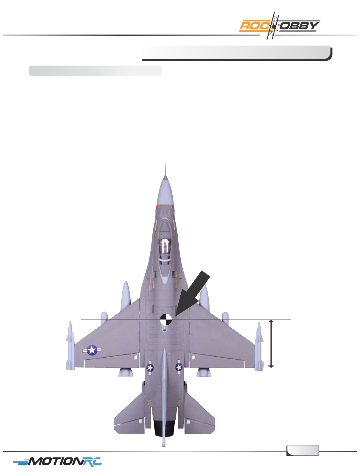
Check the C.G. (Center of Gravity)
Center of Gravity
When balancing your model, adjust the motor battery as necessary so the model is level or
slightly nose down. This the correct balance point for your model. After the first flights, the CG
position can be adjusted for your personal preference.
1. The recommended Center of Gravity (CG) location for your model is ( ) forward from170-172mm
the trailing edge of the main wing (as shown) with the battery pack installed. Mark the location of the
CG on top of the wing.
2. When balancing your model, support the plane inverted at the marks made on the top of the
main wing with your fingers or a commercially available balancing stand. This is the correct
balance point for your model. Make sure the model is assembled and ready for flight before
balancing.
170-172mm
For More Info Vist: www.motionrc.com
page13
Page 18

Get your model ready to fly
Important ESC information
1. The ESC included with the F-16 has a safe start. If the motor battery is connected to
the ESC and the throttle stick is not in the low throttle or off position, the motor will not
start until the throttle stick is moved to the low throttle or off position. Once the throttle
stick is moved to the low throttle or off position, the motor will emit a series of beeps.
Several beeps with the same tune means the ESC has detect the cells of the battery.
The count of the beeps equal the cells of the battery. The motor is now armed and will
start when the throttle is moved.
2. The motor and ESC come pre-connected and the motor rotation should be correct.
If for any reason the motor is rotating in the wrong direction, simply reverse two of the
three motor wires to change the direction of rotation.
3. The motor has an optional brake setting. The ESC comes with the brake switched off
and we recommended that the F-16 be flown with the brake off . However, the brake
could be accidentally switched on if the motor battery is connected to the ESC while the
throttle stick is set at full throttle. To switch the brake off, move the throttle stick to full
throttle and plug in the motor battery. The motor will beep Move the throttle one time.
stick to low throttle or the off position. The motor is ready to run and the brake will be
switched off.
We recommend the 11.1V 1800mAh 25C Li-Po 4. Battery Selection and Installation.
battery. If using another battery, the battery must be at least a 11.1V 1800mAh 25C
battery. Your battery should be approximately the same capacity ,dimension and
weight as the 11.1V 1800mAh 25C Li-Po battery to fit in the fuselage without changing
the center of gravity significantly.
page14
For More Info Vist: www.motionrc.com
Page 19
Get your model ready to fly
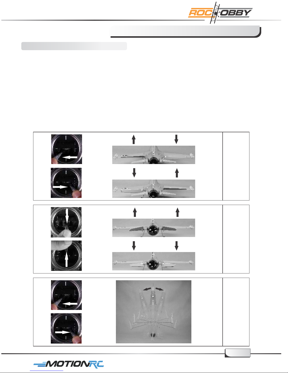
The transmitter and model setup
Before getting started, bind your receiver with your transmitter. Please refer to your
Transmitter Manual for proper operation.
CAUTION: To prevent personal injury, DO NOT install the propeller assembly onto the
motor shaft while testing the control surfaces . DO NOT arm the ESC and do not turn on
the transmitter until the Transmitter Manual instructs you to do so.
Tips: Make sure all control sticks on your radio are in the neutral position (rudder,
elevator, ailerons) and the throttle in the OFF position. Make sure both ailerons
move up and down (travel) the same amount. This model tracks well when the
left and right ailerons travel the same amount in response to the control stick.
1. Move the controls on the transmitter to make sure aircraft control surface move
correctly. See diagrams below.
Bank Left
Aileron
Bank Right
Climb
Descend
Steer Left
Left
steering
Elevator
Right
steering
Steering
Steer Right
page15
For More Info Vist: www.motionrc.com
Page 20
Get your model ready to fly
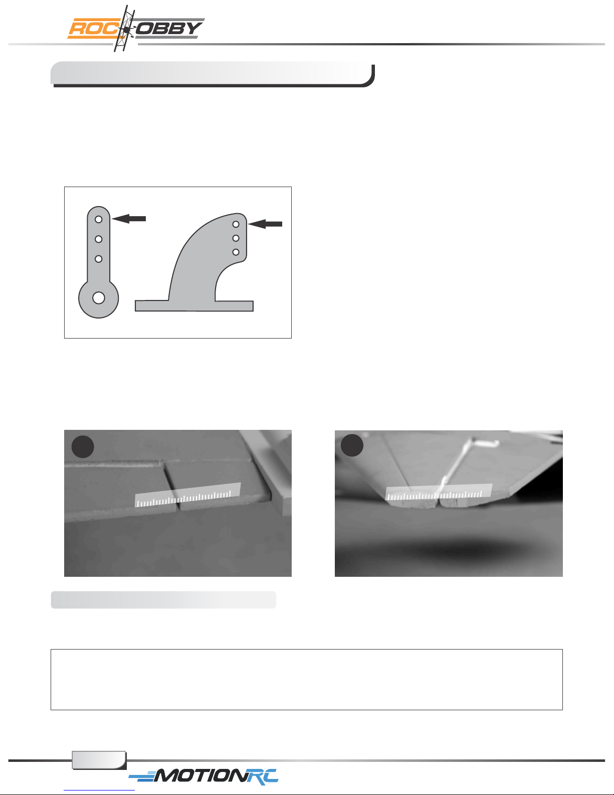
2. Make sure all servo arms are fully vertical. If not, adjust the servo arm by using the trim
function on your radio. Note: For computerized transmitters, use the servo/channel
sub-trim feature to make each servo arm fully vertical.
3. The standard hole settings for linkage connections are shown by the black arrows in the
the diagram below. You can move the linkage to different hole positions to increase
control surface travel and increase the aerobatics of the airplane.
4. Align the control surface with the wing root by turning the clevis clockwise and
counterclockwise on the linkage, carefully open the clevis fork and put the clevis pin in
the desired hole of the control horn.
Note: Please secure the clevis with provided piece of tube after the alignment of the
surface is completed.
4.1
4.2
Check the control throws
The suggested control throw settings for ROC HOBBY are as follows (Dual rate setting):
High Rate Low Rate
Elevator 15mm up/down 10mm up/down
Aileron 17mm up/down 11mm up/down
Front landing gear steering: left/right 30 degree
Tips: At first flight, fly the model in low rate. The first time you use high rates, be sure to fly
at low to medium speeds. High rates, as listed, are only for EXTREME maneuvering.
page16
For More Info Vist: www.motionrc.com
Page 21
Get your model ready to fly
Check the motorrotatingdirection
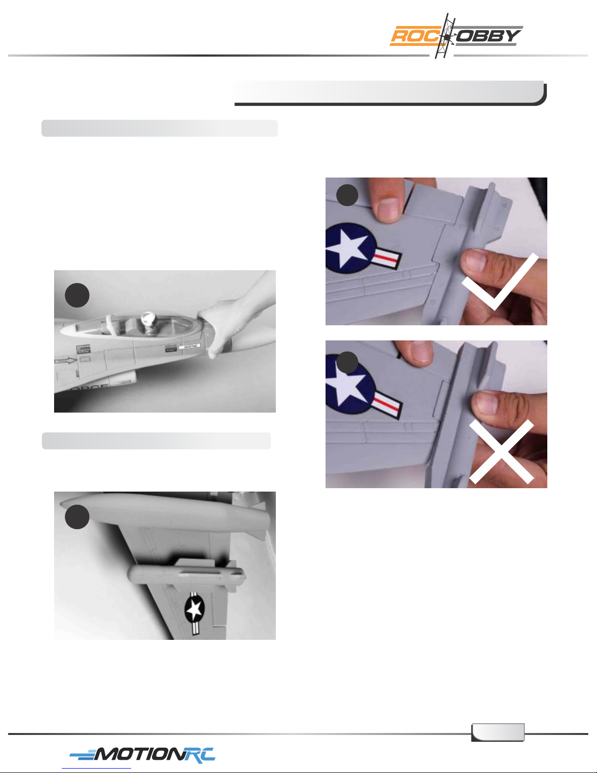
1. Caution: Never visually test the rotating
direction of the rotor due to it’s vectored
thrust. Before testing the rotor, hold the
model firmly on the ground as the picture
shows, and ensure the air inlet and outlet
are clear of small object or scrap (this will
prevent damage to the rotor). Slowly
power up the throttle; the fan(s) should
push the plane forward.
1
2. Correctly mount the wing tip missiles.
The missiles are correctly mounted when
the top of the missiles are level with the
surface of the main wing.
2.1
2.2
Load the aircraft
1. Glue the missiles and the fuel tanks
to the main wing as shown in the picture.
1
page17
For More Info Vist: www.motionrc.com
Page 22
Before the model flying
Find a suitable flying site
Find a flying site clear of buildings, trees, power lines and other obstructions. Until you
know how much area will be required and have mastered flying your plane in confined
spaces, choose a site which is at least the size of two to three football fields – a flying
field specifically for R/C planes is best. Never fly near people– especially children who
can wander unpredictably.
As a precaution, an operational ground range test should be performed before the
first flight each time you go out. Performing a range test is a good way to detect
problems that could cause loss of control such as low batteries, defective or
damaged radio components, or radio interference. This usually requires an
assistant and should be done at the actual flying site you will be using.
First turn on the transmitter, then install a fully-charged battery into the fuselage.
Connect the battery and install the hatch.
Remember, use care not to bump the throttle stick, otherwise, the propeller / fan
will turn and possibly cause damage or injury.
Note: Please refer to your Transmitter Manual that came with your radio control
system to perform a ground range check. If the controls are not working correctly
or if anything seems wrong, do not fly the model until you correct the problem.
Make certain all the servo wires are securely connected to the receiver and the
transmitter batteries have a good connection.
Monitor your flight time
Monitor and limit your flight time using a timer (such as one on a wrist watch or in your
transmitter if available). When the batteries are getting low you will usually notice a
performance drop before the ESC cuts off motor power, so when the plane starts flying
slower you should land. Often (but not always) power can be briefly restored after the
motor cuts off by holding the throttle stick all the way down for a few seconds.
To avoid an unexpected dead-stick landing on your first flight, set your timer to a
conservative 4 minutes. When your alarm sounds you should land right away.
page18
For More Info Vist: www.motionrc.com
Page 23
Flying course
Take off
While applying power slowly steer to keep the model straight, the F-16 should accelerate
quickly. As the model gains flight speed, you will want to climb at a steady and even rate.
The F-16 will climb out at a nice angle of attack (AOA).
Flying
Always choose a wide-open space for flying your plane. It is ideal for you to fly at a
sanctioned flying field. If you are not flying at an approved site, always avoid flying near
houses, trees, wires and buildings. You should also be careful to avoid flying in areas
where there are many people, such as busy parks, schoolyards, or soccer fields. Consult
laws and ordinances before choosing a location to fly your aircraft. After takeoff, gain some
altitude. Climb to a safe altitude and begin to trim the model till it’s tracks well through all
aspects of flight, including high speed passes, inverted flight, loops, and point rolls.
Landing
Land the model when you hear the motor pulsing (LVC) or if you notice a reduction in
power. If using a transmitter with a timer, set the timer so you have enough flight time to
make several landing approaches.
Recharge the battery and repair the model as needed. The model’s three point landing gear
allows the model to land on hard surfaces. Align model directly into the wind and fly down to
the ground. Fly the airplane down to the ground using 1/4-1/3 throttle to keep enough energy
for proper flare. Before the model touches down, always fully decrease the throttle to avoid
damaging the rotor or other components. The key to a great landing is to manage the power
and elevator all the way to the ground and set down lightly on the main landing gear. After a
few flights you will find the F-16 can be set down lightly on the mains and you can hold the
nose wheel off balancing the model on the mains till it slows and gently settles the nose.
Maintenance
Repairs to the foam should be made with foam safe adhesives such as hot glue, foam
safe CA, and 5 min epoxy. When parts are not repairable, see the Spare Parts List for
ordering by item number.
Always check to make sure all screws on the aircraft are tightened. Pay special attention
to make sure the bullet of the rotor adaptor is firmly in place before every flight.
page19
For More Info Vist: www.motionrc.com
Page 24
Troubleshooting
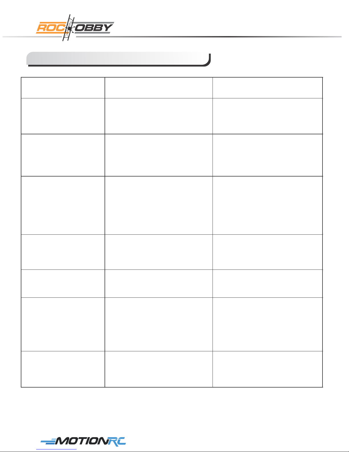
Problem
Aircraft will not
respond to the
throttle but responds
to other controls.
Extra propeller noise
or extra Vibration.
Reduced flight time or
aircraft underpowered.
Control surface does
not move, or is slow to
respond to control
inputs.
Possible Cause Solution
- ESC is not armed.
- Throttle channel is reversed.
- Damaged spinner, propeller,
motor, or motor mount.
- Loose propeller and spinner
parts.
- Propellor installed backwards.
- Flight battery charge is low.
- Propeller installed backward.
- Flight battery damaged.
- Control surface, control horn,
linkage or servo damage.
- Wire damaged or connections
loose.
- Lower throttle stick and throttle
trim to lowest settings.
- Reverse throttle channel on
transmitter.
- Replace damaged parts.
- Tighten parts for propeller
adapter, propeller and spinner.
- Remove and install propeller
correctly.
- Completely recharge flight
battery.
- Replace flight battery
and obey flight battery
instructions.
- Replace or repair damaged
parts and adjust controls.
- Do a check of connections for
loose wiring.
Controls reversed.
- Motor loses power.
- Motor power pulses
then motor loses power.
LED on receiver
flashes slowly.
Channels are reversed
in the transmitter.
- Damage to motor, or battery.
- Loss of power to aircraft.
- ESC uses default soft Low
Voltage Cutoff(LVC).
Power loss to receiver.
Do the Control Direction Test
and adjust controls
for aircraft and transmitter.
- Do a check of batteries,
transmitter, receiver, ESC,
motor and wiring for damage
(replace as needed).
- Land aircraft immediately and
Recharge flight battery.
- Check connection from ESC to
receiver.
- Check servos for damage.
- Check linkages for binding.
For More Info Vist: www.motionrc.com
Page 25

AMA
AMA
If you are not already a member of the AMA, please join, The AMA is the governing body
of model aviation and membership provided liability insurance coverage, protects
modelers’ rights and interests and is required to fly at most R/C sites.
Academy of Model Aeronautics
5151 East Memorial Drive
Muncie, IN 47302-9252
Ph.(800)435-9262
Fax(765)741-0057
Or via the Internet at: http//www.modelaircraft.org
Academy of Model Aeronautics National Model Aircraft Safety Code
A. GENERAL: A model aircraft is a non-human-carrying aircraft capable of sustained
flight in the atmosphere. It may not exceed limitations of this code and is intended
exclusively for sport, recreation and/or competition.
All model flights must be conducted in accordance with this safety code and any
additional rules specific to the flying site.
1. Model aircraft will not be flown:
(a) In a careless or reckless manner.
(b) At a location where model aircraft activities are prohibited.
2. Model aircraft pilots will:
(a) Yield the right of way to all man carrying aircraft.
(b) See and avoid all aircraft and a spotter must be used when appropriate.
(AMA Document #540-D-See and Avoid Guidance.)
(c) Not fly higher than approximately 400 feet above ground level within three (3) miles
of an airport, without notifying the airport operator.
(d) Not interfere with operations and traffic patterns at any airport, heliport or seaplane
base except where there is a mixed use agreement.
(e) Ensure the aircraft is identified with the name and address or AMA number of
the owner on the inside or affixed to the outside of the model aircraft.
(This does not apply to model aircraft flown indoors).
( f ) Not operate aircraft with metal-blade propellers or with gaseous boosts except for
helicopters operated under the provisions of AMA Document #555.
(g ) Not operate model aircraft while under the influence of alcohol or while using any
drug which could adversely affect the pilot’s ability to safely control the model.
(h ) Not operate model aircraft carrying pyrotechnic devices which explode or burn,
or any device which propels a projectile or drops any object that creates a hazard
to persons or property.
For More Info Vist: www.motionrc.com
Page 26

AMA
Exceptions:
◆ Free Flight fuses or devices that burn producing smoke and are securely attached to
the model aircraft during flight.
◆ Officially designated AMA Air Show Teams (AST) are authorized to use devices and
practices as defined within the Team AMA Program Document (AMA Document #718).
3. Model aircraft will not be flown in AMA sanctioned events, air shows or model
demonstrations unless:
(a) The aircraft, control system and pilot skills have successfully demonstrated all
maneuvers intended or anticipated prior to the specific event.
(b) An inexperienced pilot is assisted by an experienced pilot.
4. When and where required by rule, helmets must be properly worn and fastened.
They must be OSHA, DOT, ANSI, SNELL or NOCSAE approved or comply with
comparable standards.
B. RADIO CONTROL (RC)
1. All pilots shall avoid flying directly over unprotected people, vessels, vehicles or
structures and shall avoid endangerment of life and property of others.
2. A successful radio equipment ground-range check in accordance with manufacturer’s
recommendations will be completed before the first flight of a new or repaired model
aircraft.
3. RC model aircraft must use the radio-control frequencies currently allowed by the
Federal Communications Commission (FCC). Only individuals properly licensed by
the FCC are authorized to operate equipment on Amateur Band frequencies.
4. RC model aircraft will not operate within three (3) miles of any pre-existing flying site
without a frequency-management agreement (AMA Documents #922-Testing for RF
Interference; #923- Frequency Management Agreement)
5. With the exception of events flown under official AMA Competition Regulations,
excluding takeoff and landing, no powered model may be flown outdoors closer than
25 feet to any individual, except for the pilot and the pilot's helper(s) located at the
flight line.
6. Under no circumstances may a pilot or other person touch a model aircraft in flight
while it is still under power, except to divert it from striking an individual.
This does not apply to model aircraft flown indoors.
7. RC night flying requires a lighting system providing the pilot with a clear view of the
model’s attitude and orientation at all times.
8. The pilot of a RC model aircraft shall:
(a) Maintain control during the entire flight, maintaining visual contact without
enhancement other than by corrective lenses prescribed for the pilot.
(b) Fly using the assistance of a camera or First-Person View (FPV) only in accordance
with the procedures outlined in AMA Document #550.
C. FREE FLIGHT
1. Must be at least 100 feet downwind of spectators and automobile parking when the
model aircraft is launched.
2. Launch area must be clear of all individuals except mechanics, officials, and other fliers.
3. An effective device will be used to extinguish any fuse on the model aircraft after the
fuse has completed its function.
page22
For More Info Vist: www.motionrc.com
 Loading...