

Page 1
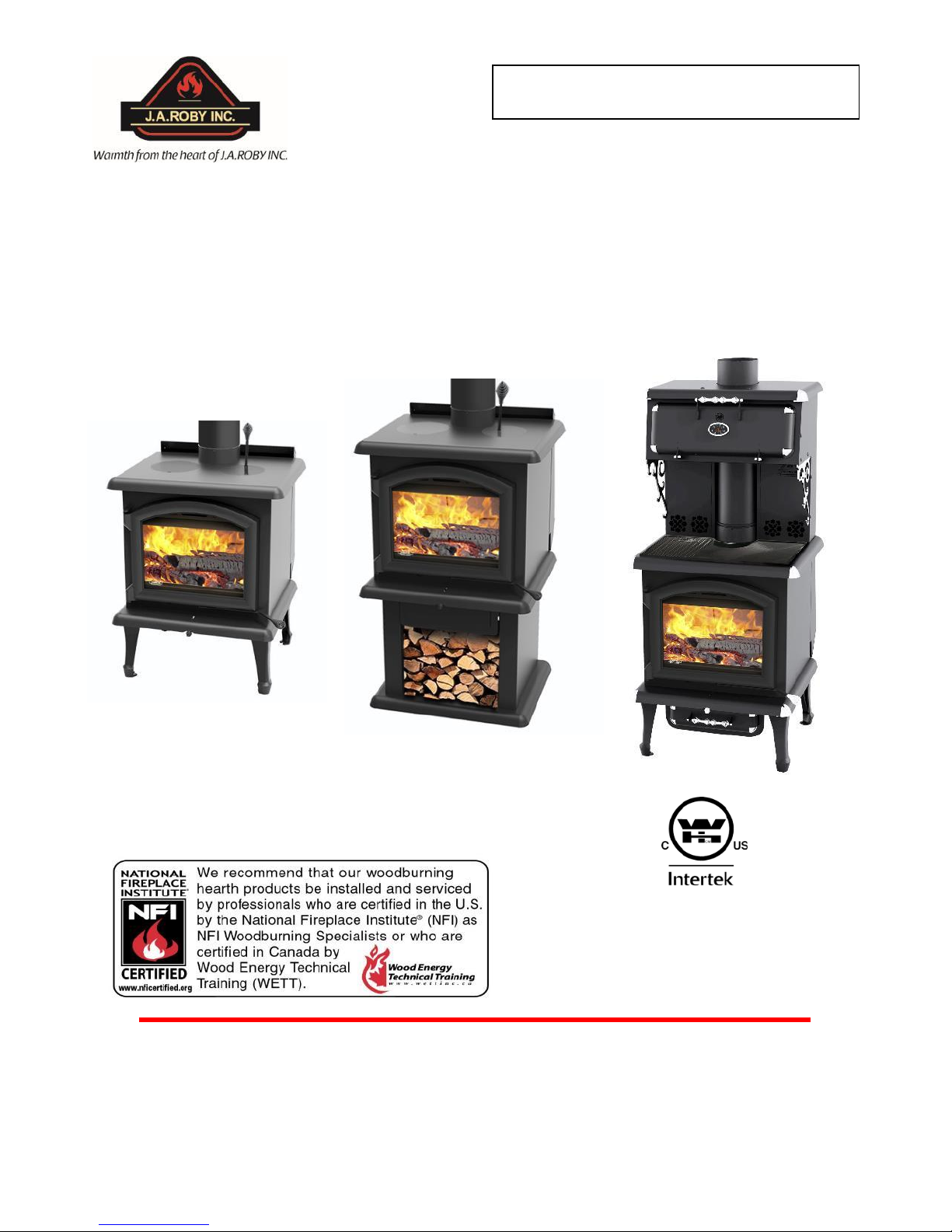
Instruction Manual
490, rue de l'Argon
Québec, CANADA G2N 2C9
Tél.: 418-849-8095 Fax : 418-849-0077
www.jaroby.com
Certified and tested according to
emission standard
PLEASE READ CAREFULLY AND KEEP
THIS MANUAL FOR FUTURE REFERENCE
Product # 10-000
POLARIS — VEGA — CENTAURI
CAN/ULC S627-00
UL 1482-2011
2020 U.S. Environmental
Protection Agency's crib wood
June 16, 2016 Printed in Canada
Page 2

TABLE OF CONTENTS
INTRODUCTION ...................................................................... 3
LISTING AND CODE APPROVALS ......................................... 3
Appliance certification .......................................................... 3
Mobile home approved......................................................... 3
BTU & Efficiency Specifications ........................................... 3
WARNING ................................................................................ 3
RATING PLATE ....................................................................... 4
APPLIANCE DIMENSION ........................................................ 5
SPECIFICATIONS ................................................................... 5
CLEARANCES TO COMBUSTIBLE MATERIAL ...................... 5
INSTALLATION ........................................................................ 6
Fire Prevention ..................................................................... 6
Floor protection .................................................................... 6
Floor protection plate minimum dimensions .................... 6
Clearances of the stove until the floor plate protection .... 6
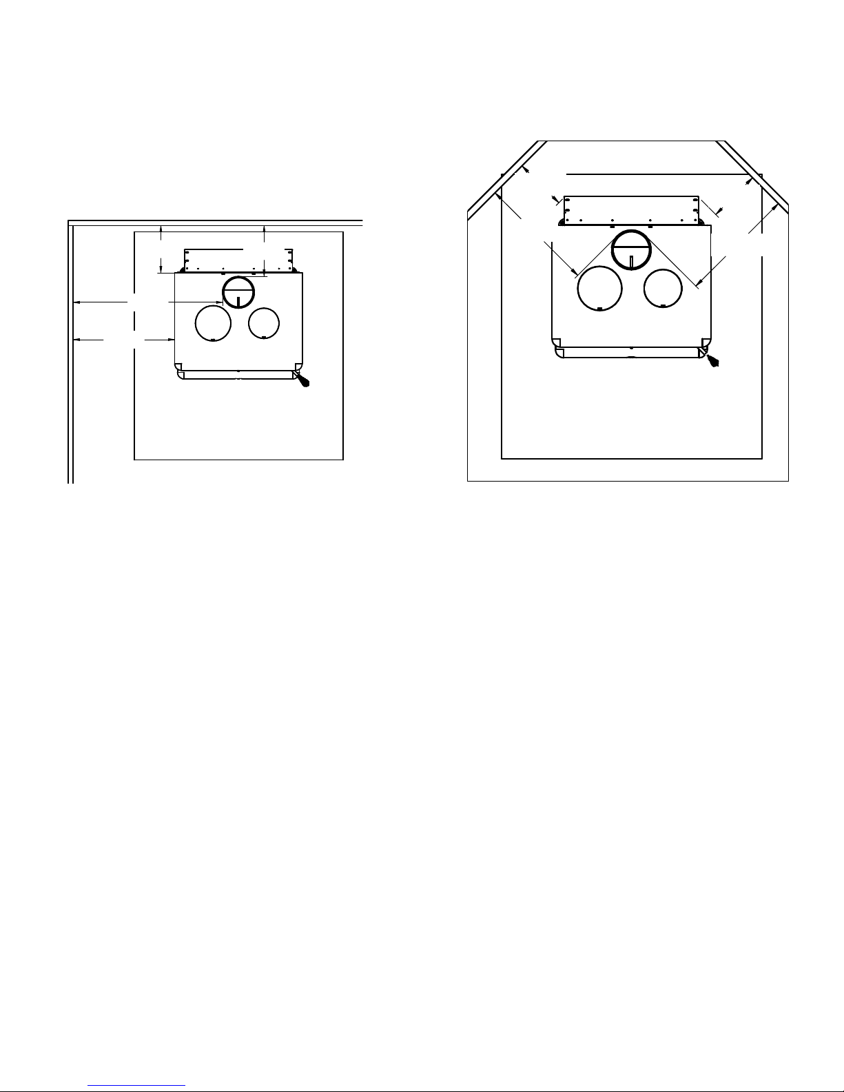
Minimums clearances to combustible material ..................... 7
Assembly before installation ................................................ 8
Leg installation ................................................................. 8
Pedestal installation ......................................................... 8
Fan and Snap disc box installation .................................. 8
Warmer stove Assembly (Optional) ................................. 9
Firebricks installation.......................................................... 11
Side firebrick installation ................................................ 11
Back firebrick installation ............................................... 11
Floor firebricks installation ............................................. 11
Angle firebricks installation ............................................ 11
Firebrick installation on the pipes................................... 12
GENERAL STOVE INSTALLATION STEPS .......................... 13
Location considerations ..................................................... 13
General steps of installation ............................................... 13
Chimney connector installation .......................................... 14
Mobile home installation..................................................... 15
Chimney installation, General steps ................................... 16
Inside Masonry Chimney, Vertical Installation ............... 17
Outside Vertical Installation ........................................... 17
Cathedral Vertical Installation ........................................ 17
Offset Installation ........................................................... 18
Vertical Installation......................................................... 19
EXTERNAL COMBUSTION AIR SOURCE ............................ 20
Exterior Air Intake pipe ....................................................... 20
Installation of Air Intake Pipe ......................................... 20
Air Inlet Obstruction ....................................................... 20
June 16, 2016
STAINLESS STEEL TUBES REPLACEMENT ...................... 21
Stainless steel tubes Installation ........................................ 21
How to install tubes ....................................................... 21
OPERATING INSTRUCTIONS .............................................. 22
Primary and secondary air admission control .................... 22
Lightning fire ...................................................................... 22
First fire .............................................................................. 23
Keep a fire ......................................................................... 23
Fan Control ........................................................................ 23
Fuel Selection .................................................................... 23
Moisture Meter Information ............................................ 23
Things not to burn .......................................................... 24
Wood storage .................................................................... 24
Draft ................................................................................... 24
MAINTENANCE ..................................................................... 24
Ash Removal ..................................................................... 24
Ash Disposal ...................................................................... 24
Creosote Formation ........................................................... 24
Chimney Inspection ........................................................... 25
Chimney Sweeping ............................................................ 25
Door maintenance.............................................................. 25
Air tight Adjustment ............................................................ 25
Door adjustment (right side) .......................................... 25
Cleaning up glass .......................................................... 25
Uninstalling and installing door ...................................... 25
Replacing broken glass ................................................. 26
Fiberglass rope replacement ......................................... 26
WHAT TO DO IN CASE OF CHIMNEY FIRE ........................ 26
APPENDIX 1 .......................................................................... 27
Exploded diagram of door .................................................. 27
APPENDIX 2 .......................................................................... 27
Fans electric wiring diagram .............................................. 28
APPENDIX 3 .......................................................................... 29
Parts that can be replaced ................................................. 29
ANNEXE 4 ............................................................................. 30
Pedestal installation ........................................................... 30
APPENDIX 5 .......................................................................... 33
Dimension and quantity of bricks ....................................... 33
J. A. ROBY LIMITED LIFE WARRANTY ................................ 34
Page 3

INTRODUCTION
This manual describes the operation and installation of J.A.
Roby woodstove model: Polaris, Centauri, Antares, Sirius, Rigel,
and Vega. This appliance responds to 2020 US Environment
Protection with sized controlled crib wood. The capacity of this
appliance is from 11000 BTU/h to 27000 BTU/h.
Read all instructions carefully before installing your new J.A.
Roby stove. A good installation is very important for a safe and
effective use of this appliance. If you have doubts about the
instruction to install your appliance correctly, we suggest to call
a professional installer. A wrong installation may result in a fire,
burns and possible death.
Keep these instructions for future reference.
This appliance must be connect to:
A HT type factory-built chimney approved UL103 or ULC
629 with 6 inches diameter (15.24 cm);
A code-approved masonry chimney with a flue liner with a
6 inches diameter (15.24cm).
LISTING AND CODE APPROVALS
Appliance certification
The Polaris, Antarès, Sirius, Centauri, Rigel, Véga wood stove
meets the 2020 U.S. Environmental Protection Agency's crib
wood emission standard.
This appliance also meet:
UL 1482-2011 Standard for Solid-Fuel Type Room
Heaters;
ULC S627-00 Standard for Space Heaters for Use
with Solid Fuels;
(UM) 84-HUD, Mobile Home approved.
This wood heater has a manufacturer-set minimum low burn rate
that must not be altered. It is against federal regulations to alter
this setting or otherwise operate this wood heater in a manner
inconsistent with operating instructions in this manual.
This wood heater needs regular inspection and repair for
proper operation. It is against federal regulations to operate
this stove in a manner inconsistent with the instruction in this
manual.
Mobile home approved
This appliance is approved for mobile home installations. The
structural integrity of the mobile home floor, ceiling, and walls
must be maintained. The appliance must be properly grounded
to the frame of the mobile home and used only a listed doublewall connector pipe.
The appliance must be fixed on the floor.
Do not install in a sleeping room.
Exterior air inlet is mandatory for mobile home use.
BTU & Efficiency Specifications
Average efficiency 75.66%
Particle emission 1.36g/h
Minimum Heat Output* 11'440 BTU/hr
Maximum Heat Output* : 27'214 BTU/hr
Vent size 6"
Firebox size 1.83 cubic feet
Recommended wood length: 18 inches
Fuel Orientation: side to side.
Fuel: Seasoned cord wood.
* A range of BTU outputs based on Environment Protection
Agency Default Efficiency and the burn rates from the low and
high Environment Protection Agency emission tests, using
Douglas fir dimensional lumber.
WARNING
If this appliance is in an area where children may be near, it
is recommended that you place a decorative barrier in front
of the appliance.
N.B: BE WARNED THAT THE LOCAL CODES AND RULES
CAN HAVE MORE SPECIFIC REQUIREMENT THAN THIS
MANUAL. YOU CAN CONSULT A PROFESSIONAL
INSTALLER, OR ASK FIRE OFFICIALS OR LOCAL
AUTHORITY ABOUT RESTRICTION AND INSTALLATION
INSPECTION IN YOUR AREA.
YOU MIGHT NEED TO OBTAIN A PERMIT FOR INSTALLING
CHIMNEY AND STOVE.
DO NOT CONNECT THIS APPLIANCE TO A CHIMNEY FLUE
SERVING ANOTHER APPLIANCE.
DO NOT CONNECT TO OR USE IN CONJUNCTION WITH
ANY AIR DISTRIBUTION DUCTWORK UNLESS
SPECIFICALLY APPROVED FOR SUCH INSTALLATIONS.
THIS APPLIANCE IS BUILT FOR BURNING SEASONED
CORDWOOD ONLY. USE OF ANY OTHER TYPE OF FUEL
LIKE COAL/ CONSTRUCTION WOOD/ TREATED WOOD/
FLAMABLE LIQUID/ TRASH/ OR ANY FLAMABLE THING
CAN OVERFIRE AND DAMAGE THE STOVE.
June 16, 2016 3
Page 4
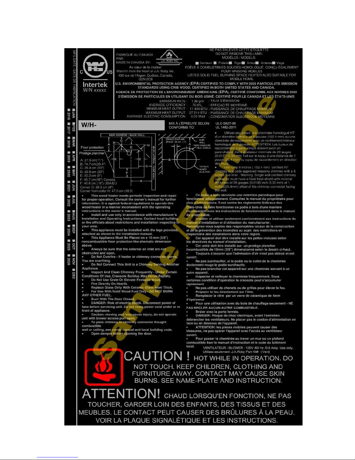
RATING PLATE
June 16, 2016 4
Page 5
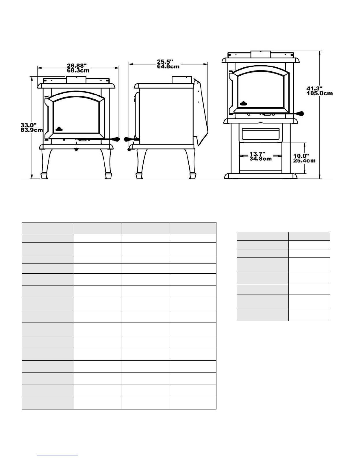
Option
Polaris, Sirius
Vega, Antares
Rigel, Centauri
Combustible
Wood
Wood
Wood
Recommended
surface area
1800 ft²
1800 ft²
1800 ft²
Capacity
27214 BTU/h
27214 BTU/h
27214 BTU/h
Flue pipe diameter
6 in (15.4 cm)
6 in (15.4 cm)
6 in (15.4 cm)
Minimal chimney
height
12 ft (366 cm)
12 ft (366 cm)
12 ft (366 cm)
Exterior Height
33 in (83.8 cm)
41.3 in
(104.1 cm)
54 1/8 in
(137.5 cm)
Exterior Width
26 7/8 in
(68.3 cm)
26 7/8 in
(68.3 cm)
26 7/8 in
(68.3 cm)
Exterior Depth
25 ½ in
(64.8 cm)
25 ½ in
(64.8 cm)
25 ½ in
(64.8 cm)
Door Opening
15 5/8 in x 9 1/8 in
40.0 cm x 23.2 cm
15 5/8 in x 9 1/8 in
40.0 cm x 23.2 cm
15 5/8 in x 9 1/8 in
40.0 cm x 23.2 cm
Interior Height
10 7/8 in
(27.6 cm)
10 7/8 in
(27.6 cm)
10 7/8 in
(27.6 cm)
Interior Width
18 3/8 in
(46.7 cm)
18 3/8 in
(46.7 cm)
18 3/8 in
(46.7 cm)
Interior Depth
15 3/4 in
(40 cm)
15 3/4 in
(40 cm)
15 3/4 in
(40 cm)
Maximum log
length
18 in
(45.7 cm)
18 in
(45.7 cm)
18 in
(45.7 cm)
Average
combustion time
3 to 8 hours
3 à 8 heures
3 à 8 heures
Weight
266 lb
(120.7 kg)
297 lb
(134.7 kg)
320 lb
(145.1 kg)
All models
Back
10 in (25.4 cm)
Beside
20 in (50.8 cm)
Front
48 in
(121.9 cm)
Minimum Ceiling
Height
84 in
(213.4 cm)
Back of Flue Collar
11 in (27.9 cm)
Side of Flue Collar
29.4 in
(74.6 cm)
In corner
installation
8 inches
(20.3 cm)
APPLIANCE DIMENSION
SPECIFICATIONS
CLEARANCES TO
COMBUSTIBLE
MATERIAL
June 16, 2016 5
Page 6
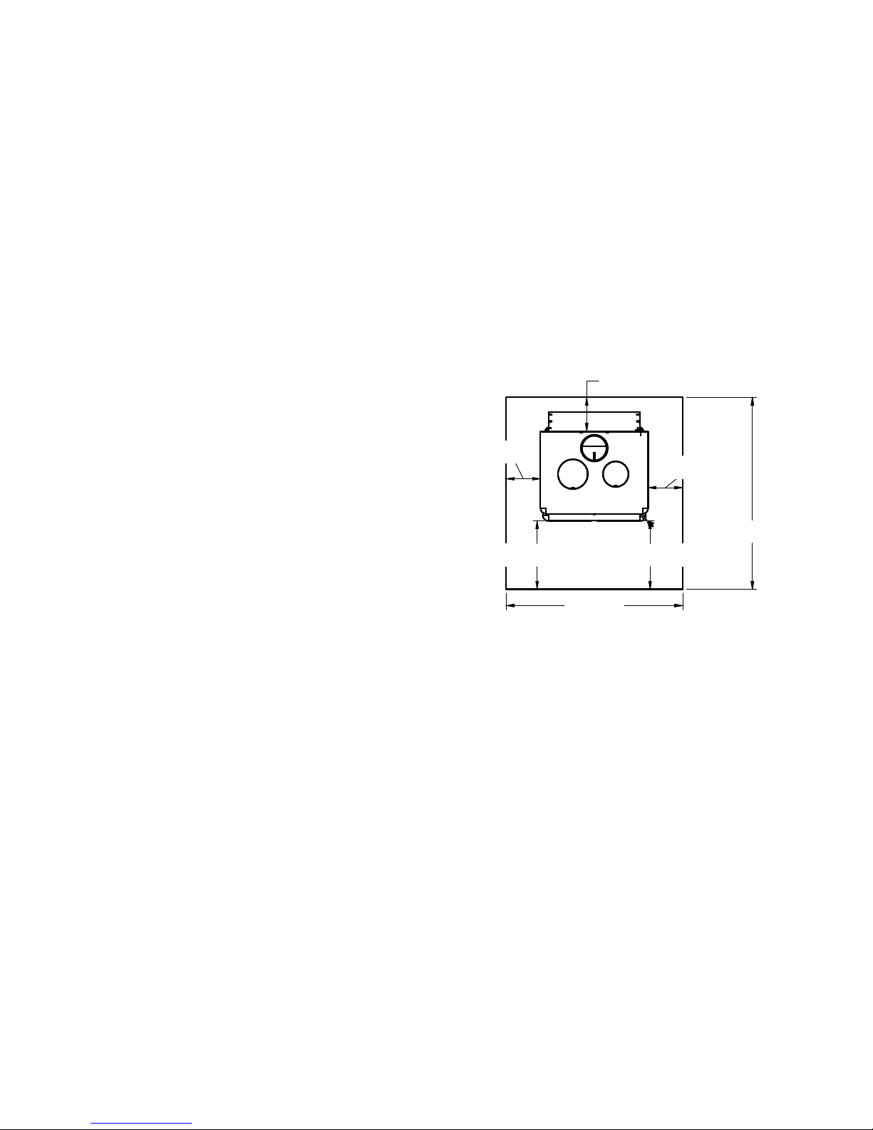
8.0"
20.3cm
8.0"
20.3cm
8.0"
20.3cm
45.0"
114.3cm
ÉU/USA
16.0"
40.7cm
ÉU/USA
47.0"
119.4cm
Canada
18.0"
45.7cm
Canada
41.2"
104.8cm
INSTALLATION
Fire Prevention
To provide reasonable fire prevention, the following should be
given serious consideration:
1. At least one smoke detector on each floor of your home
should be installed to ensure your safety. They should be
located away from the heating appliance and close to the
sleeping areas. Follow the smoke detector
manufacturer’s placement and installation instructions,
and be sure to maintain regularly.
2. A conveniently located Class A fire extinguisher to
contend with small fires resulting from burning embers.
3. A CO detector should be installed in the room with the
appliance.
4. A practiced evacuation plan, consisting of at least two
escape routes.
5. A plan to deal with a chimney fire as follows:
a. In the event of a chimney fire:
b. Evacuate the house immediately
c. Notify fire department.
Floor protection
Your stove must be installed on a non-combustible material
plate to protect the floor and avoid fire caused by:
Projections of sparks when opening door or loading
logs;
The heat radiation from stove runaway which might
cause an auto-ignition to the floor and the coating;
Flow of creosote when there is a fire chimney.
The coating used for the protection must be non-combustible
and approved according to standard UL1618 for USA or
approved to the locals codes (Example: cement, brick, ceramic
tiles, etc.)
HORIZONTAL VENTING MANDATORY Non-combustible
floor protections must extend beneath the flue pipe when
installed with horizontal venting and it should extend 2 inches
(51 mm) beyond each side of the pipe.
You can extend the protection plate while respecting the
clearances of each side of stove.
Floor protection plate minimum dimensions
The following dimensions are the minimums values and it can
be higher.
Canada:
44 ¾ inches (113.73 cm)
53 ¾ inches (136.53 cm)
3/8 inch thick (1 cm)
United States:
44 ¾ inches (113.73 cm)
51¾ inches (131.44 cm)
3/8 inch thick (1 cm)
Clearances of the stove until the floor plate
protection
The following dimensions are the minimums values and it can
be higher.
Canada:
8 in (20.3 cm) behind
8 in (20.3 cm) beside
18 in (45.7 cm) in front of the door opening.
United States:
8 in (20.3 cm) behind
8 in (20.3 cm) beside
16 in (40.64 cm) in front of the door opening.
June 16, 2016 6
Page 7
29.4"
74.8cm
20.0"
50.8cm
11.0"
27.9cm
10.0"
25.4cm
18.5"
47.0cm
18.5"
47.0cm
8.0"
20.3cm
8.0"
20.3cm
Minimums clearances to combustible material
With these reduced clearances, this appliance take a minimum
space to be installed. Whether in the living room or the dining
room, this appliance will complete your decorate by his
originality and heating. It requires a minimum clearance of 10
inches (25.4 cm) to the back (for a smoke simple pipe with a
heat shield) and a 20 inches (50.8 cm) lateral MINIMUM
clearance.
For a 45° corner or other corner installation, the
minimum clearance between the stove and
combustible material must be 8 inches.
In the case with a smoke simple pipe without heat
shield, you must installed the stove that the
smoke pipe is to 18 inches (47.5 cm) of all
combustible material therefore the MINIMUM
clearance at the back of the stove will be 12½
inches (41.3cm).
To know how to reduce that dimension, you have to
contact your local authority for installing heat shield on
a wall. The Installation with reduced clearances must
comply with standard NFPA211 or CAN/CSA-B365.
June 16, 2016 7
Page 8
Fan
Screws
Grate
Star Washer
Screw
Thermodisc
Box
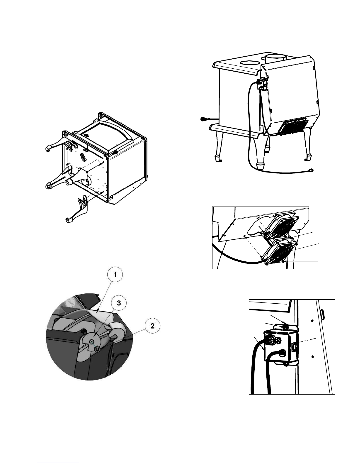
Assembly before installation
Depending on the option you chose, the stove legs might not
have been assembled in the shop in order to save space for
storage and shipping. You must therefore assemble them before
installing the stove.
Leg installation
1) Remove legs and bricks from combustion room.
2) Unscrew the stove from the skids.
3) Put the stove on the back and be careful to protect the
paint.
Fan and Snap disc box installation
1) Screw the fans on the ventilation box as illustrated.
Make sure to place the cables as shown.
4) Unscrew the nut (#2) at the corners without removing
completely.
5) Install the legs (#1) as illustrated and secure it with nut
and washer (#2, #3) (Attention: Be sure the legs are in
place, correctly positioned and in contact with the
bottom of the stove.)
Pedestal installation
See appendix 4.
2) Screw snap disc box into the holes made for that at the
back side near the vent box.
WARNING: NEVER ROUTE POWER CORD UNDER
OR IN FRONT OF THE APPLIANCE.
June 16, 2016 8
Page 9
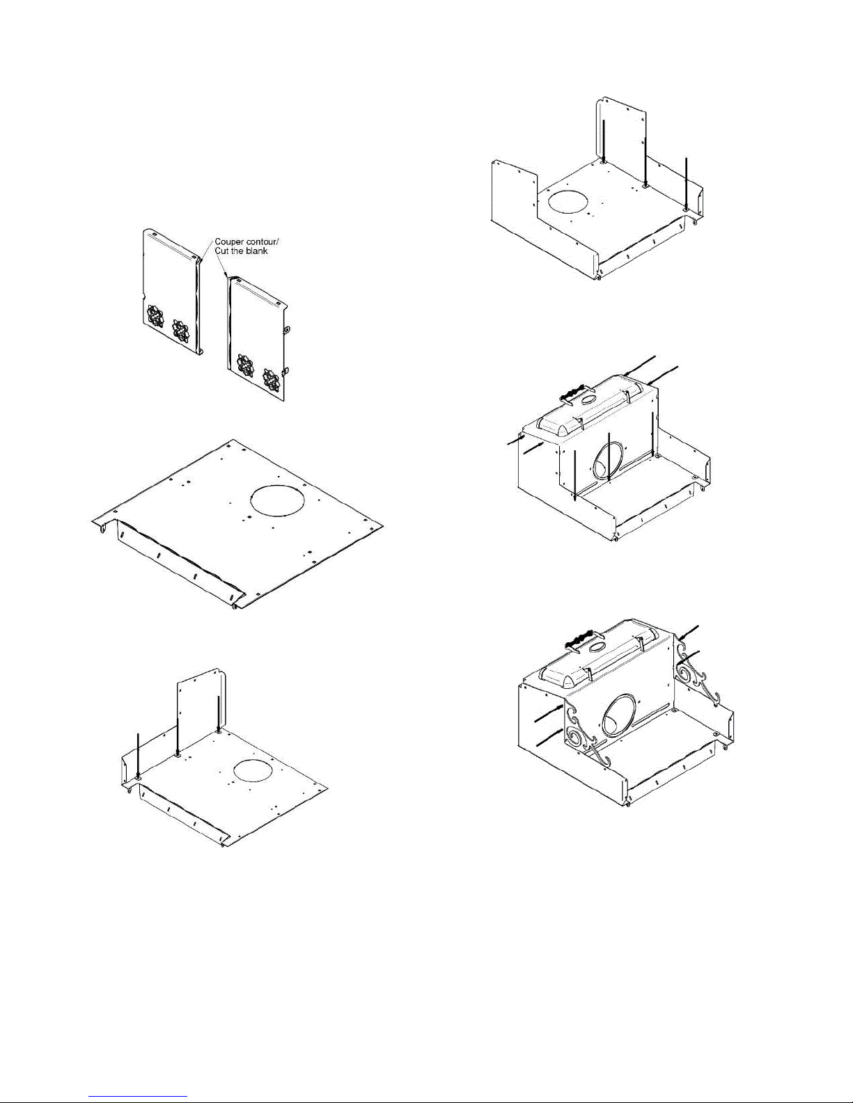
Warmer stove Assembly (Centauri Cuisiniere)
Now, you need to know which type of smoke pipe: smoke simple
pipe or smoke double pipe.
For the smoke simple pipe, it’s not necessary to remove the precut metal part.
For the smoke double pipe, you must remove the pre-cut metal
part on the top, inside and in front of the warmer. See pictures
below.
3) Fix the right side.
1) Put the packaging product on the ground and put the back
on it to protect the painted part.
2) Fix the left side.
4) Fix the front (with the door) with the two sides and the
back. Keep the horizontal holes empty for the chrome
decoration.
5) Insert the chrome decoration in the hole and fix-it with
carriage bolt and nut (2 bolts each) .
June 16, 2016 9
Page 10
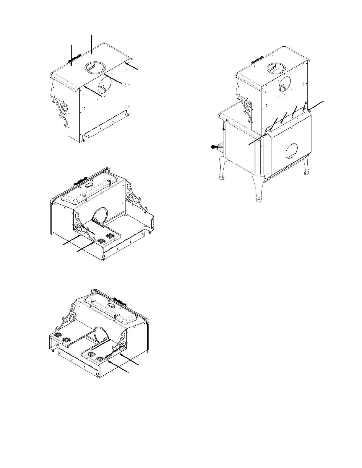
6) Fix the top with the back and with the front as well.
7) Fix the left decorative panel side and install the left
chrome decoration.
9) Put and fix the warmer with the 6 holes of each side to
the cook stove.
8) Fix the right decorative panel side and finish installing
the right chrome decoration.
June 16, 2016 10
Page 11
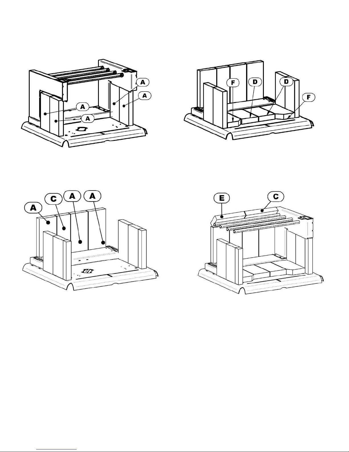
Firebricks installation
Floor firebricks installation
Side firebrick installation
Put 4 bricks "A" as shown.
Back firebrick installation
Put 3 bricks «A» and 1 brick «C» on the back wall.
Put 2 Bricks «F» near the wall and 2 bricks «D» in the center.
Angle firebricks installation
Put «C» and «E» brick on the top of the back bricks and tangent
to the last tube.
June 16, 2016 11
Page 12
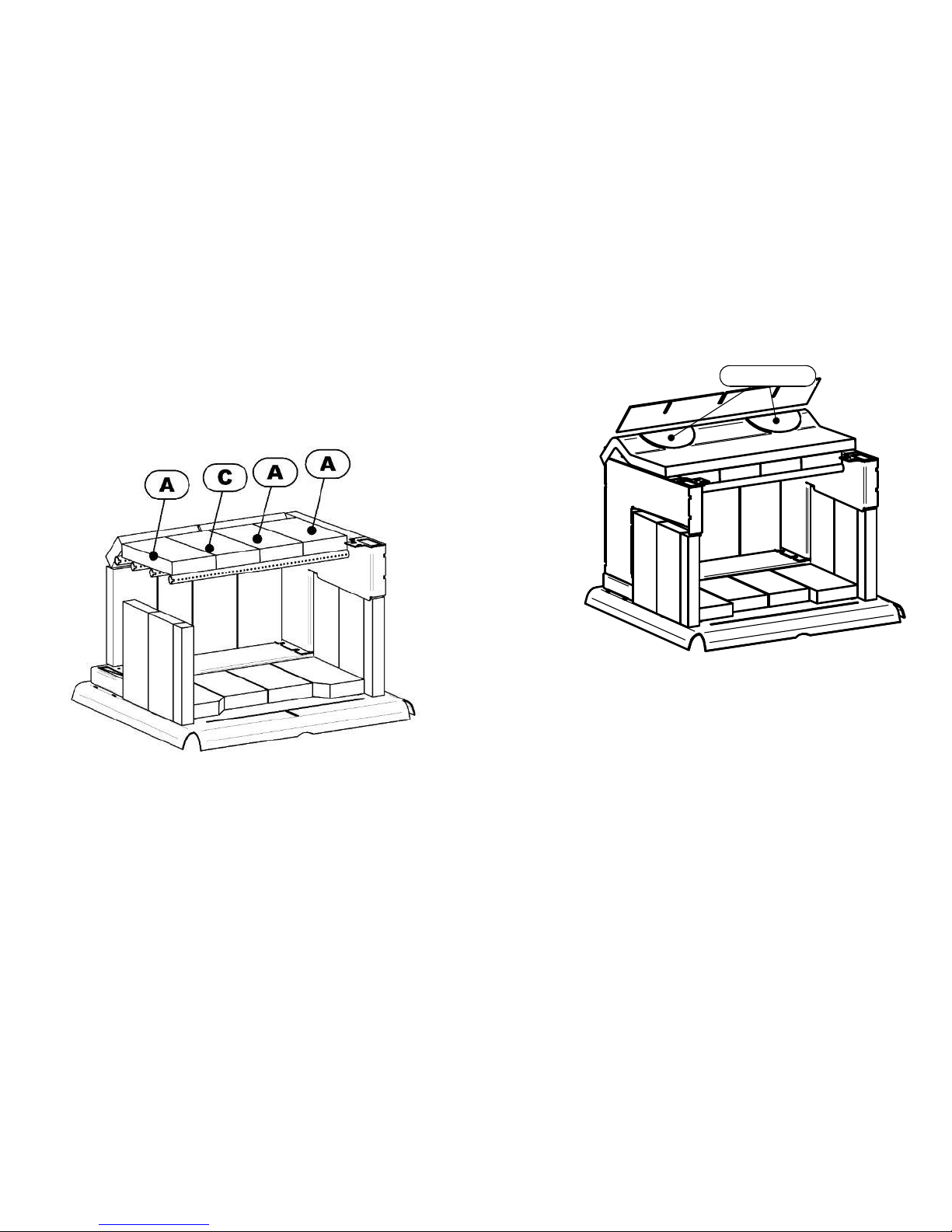
Half Disk
Firebrick installation on the pipes
The firebricks must be put on the 3 pipes from the front of
combustion chamber. Bricks keep the maximum heat inside the
combustion chamber and help the air from the tube burn the most
of the gas from wood which wouldn’t be burnt in any other
manner.
The rockwool above the brick prevents leakage between the
bricks and keep a maximum heat inside combustion chamber. It
must cover up all the bricks and the air corridors of both sides.
IMPORTANT: The rockwool must not obstruct the smoke exit
way. Check from the hole in the flue collar and make sure that is
in the good position. Place two half-round steel parts on the
rockwool as illustrated.
1) Put 3 « A » bricks and 1 «C» brick vertically over the first
three top pipes and push them against the back angle brick.
Be sure to eliminate any space between the back bricks
and the bricks you install as shown.
2) Put the rockwool over the bricks and check from the hole
in the flue collar that the passage of smoke is not
obstructed. There must be 1 inch (2.54 cm) or more
between the rockwool and the deflector.
3) Put two half-round steel disk over the rockwool near the
rear deflector already in place. Be sure to put it under the
rear deflector to maximise the clearance between
rockwool and the rear deflector. Make sure the rockwool
is not obstructig the space by looking from the hole in the
flue collar.
WARNING: Obstructing smoke exit way under deflector can
force fume to exit by the door when open it and the stove
must not work properly.
June 16, 2016 12
Page 13

GENERAL STOVE
INSTALLATION STEPS
Location considerations
We recommend installation of this appliance by a certified
installer.
Consideration must be given to:
Safety;
Traffic flow;
Convenience;
Chimney and chimney connector required;
Draft.
Drawing your installation plan on paper is a good way to avoid
mistake.
Write on the plan:
Exact dimensions for clearances to combustible
material;
Exact dimensions of the floor protection;
Measurements of the chimney location. (If it not
already installed. Be sure to have all clearances
recommended by the factory-built chimney
manufacturer to pass through the ceiling and roof).
We recommend that a qualified building inspector and your
insurance company representative review your plan before and
after installation.
General steps of installation
1) Read the entire installation manual before installing
and using your stove.
2) Choose a spot where to install your stove. Read
section about floor protection dimension, localisation of
stove over the floor protection plate and combustible
material clearance. Once you have decided where to
install the stove, mark the roof at the center of chimney.
o To be sure that the vertical center of the chimney,
use a plumb line and mark the center on the floor.
3) Check if it possible to pass chimney without damaging
the structural integrity of your house. If so, you have to
move the location of the stove while keeping the
minimum clearance or more to be sure. If you can’t
move the stove and have to cut through a beam, make
sure to keep the structural integrity of your house by
following state of the art and National building code.
o We recommend installation of this appliance by a
certified installer.
Note: This appliance have to be connected to 6 inches
(15.24 cm) factory build chimney HT UL 103 or CAN/ULC
S629 compliant or a 6 inches (15.24 cm) masonry chimney
with a homologated sleeve inside.
4) Install the chimney following the manufacturer
instruction.
5) Put the stove directly on the floor aligned vertically with
the center of chimney, and trace the side of the stove
on the floor and remove it.
6) Trace the dimension of protection plate on the floor.
There must be 8 inch (20.3 cm) clearance from the side
and the back of the stove. . From the front of the door
opening, there must be a clearance of 16 inches (40.6
cm) in US and 18 inches (45 cm) in Canada.
7) Install the floor protection plate inside the mark (It must
be non-combustible).
8) Put the stove on the protection floor plate and respect
the offset clearance set at step 6. Be sure to center the
stove under the chimney. We recommend to fix the
stove to the floor with bolt in the slot made for this
purpose in the legs. In a mobile home, it is obliged to
fix the stove.
9) If you have an outside air inlet, you must use 4 inches
(10.16 cm) flexible aluminum pipe. The pipe must be
sealed with thermal resistant sealant and it has an air
intake with grate approved for this purpose.
10) Install the chimney connector on the stove. The pipe
must be fixed with at least 3 screws on the stove collar,
each chimney connector and the chimney collar.
Note: The single wall or double wall chimney connector
must be 6 inche diameter and have a minimum thickness of
24 gauge (0.025 inches 0.64 mm). Do not use galvanised
steel chimney connector.
.
June 16, 2016 13
Page 14
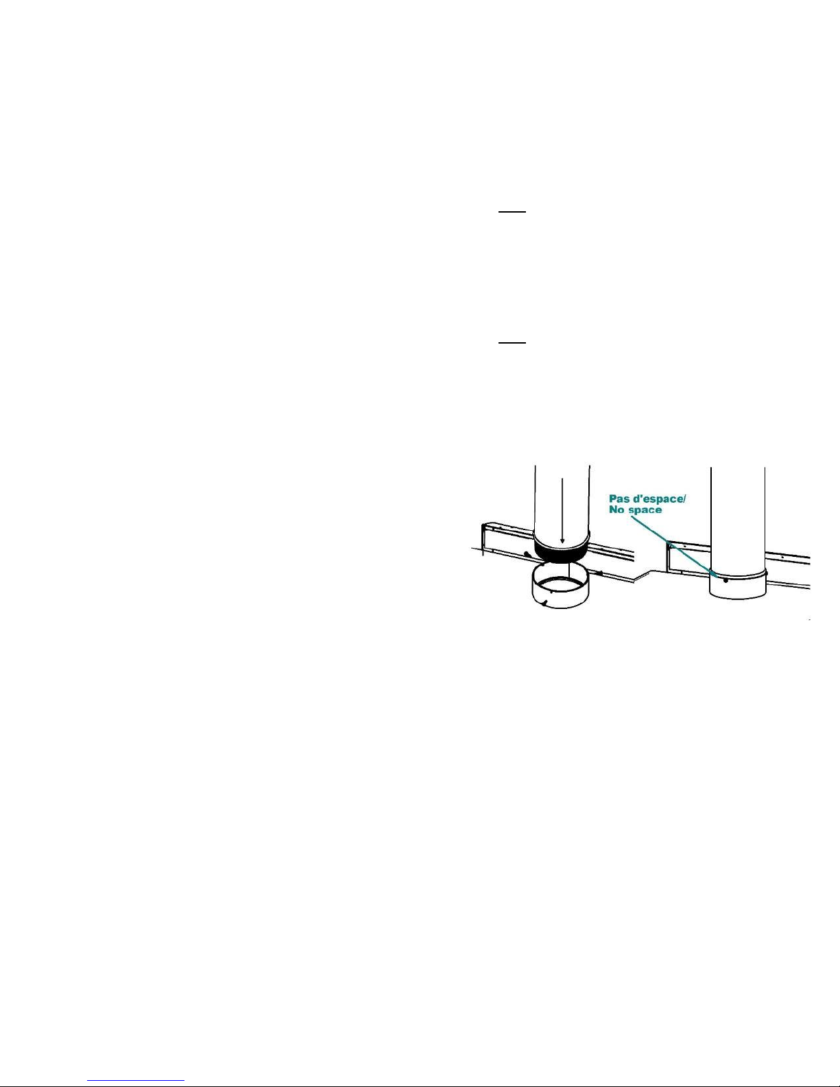
Chimney connector installation
The chimney connector is a set of single wall or double wall flue
pipes and elbow installed between the stove collar and the
chimney collar. The single wall chimney connector is sold into
any hardware store and are not approved nor certified. Some
rules must be followed to install it and can be found in the
installation codes for wood heater.
Double wall chimney connector
The stove was designed and tested with a single wall
chimney connector with heat shield. However, it is
possible to install a 6 inch (15.2 cm) double wall certified
chimney connector.
ATTENTION:
For the clearance between combustible materials and
double wall chimney connector, see manufacturer manual.
Single wall chimney connector
For the single wall chimney connector, it must be 6 inches
diameter and minimum thickness of 22 gauge 0.029 inches
(0.85 mm). Install a metal heat shield, 1 inches (25.4 mm)
offset for the single wall section and elbow.
ATTENTION:
If heat shield is not present you must move away the
stove to keep 18 inches (45.7 cm) clearance
between combustibles materials and the chimney
connector.
Any horizontal section must have a 1/4 inches (6.35
mm) by feet (30 cm) slope toward the chimney collar.
Clearance between roof and horizontal single wall
chimney connector must be 18 inch (45.7 cm) or
more.
Clearance between roof and horizontal double wall
chimney connector, follow chimney connector
manufacturer indication.
ALL SECTION AND ELBOW MUST BE CLEAN AND
IN GOOD CONDITION AND MUST BE APPROVED
FOR A CORDWOOD FUEL.
Chimney connector assembly installation
1. Make a summary installation of all sections and elbows
(if necessary) to ensure that you meet the clearances and
inclinations of the horizontal sections and verify if you
have all the necessary parts for the final installation.
o For direct vertical installation, you will need:
1 vertical section of 24 inches or more;
1 adequate length of telescopic chimney
connector section allowing you to connect
the last chimney connector to the chimney
collar.
Note: Additional section can be used for higher roof.
o For horizontal run installation you will need:
1 adequate length of vertical section
1 x 90° elbow or 2 x 45°elbow.
1 x adequate length of telescopic chimney
connector section.
Note: For better draft performance, two 45 degree
elbow are preferable, with or without straight section
in between.
2. Disassemble the whole thing and restart screwing the
pieces from the stove to the roof chimney collar
3. Insert entirely the rolled end into the stove collar and
screwing it with a minimum of 3 screws.
4. Install all the next section up to the roof chimney
support and screw every chimney connector parts with
3 screws
WARNING: It is mandatory to screw the pipe to the
stove collar and also at each joints with a minimum
of 3 screws.
5. Install all the next section and screw it to the
chimney collar.
DO NOT CONNECT CONECT THIS UNIT TO A CHIMNEY
FLUE SERVING ANOTHER APPLIANCE.
CONNECTOR PIPES SHOULD NEVER PASS THROUGH
THE CEILING, THROUGH A WALL, IN A CLOSET, IN AN
ATTIC OR OTHER ENCLOSED AREA THAT COULD
CAUSE HEAT BUILDUP. IF YOU NEED TO PASS
THROUGH COMBUSTIBLE MATERIAL, MAKE SURE
THAT YOUR INSTALLATION COMPLIES WITH
CAN/CSA-B365.
June 16, 2016 14
Page 15
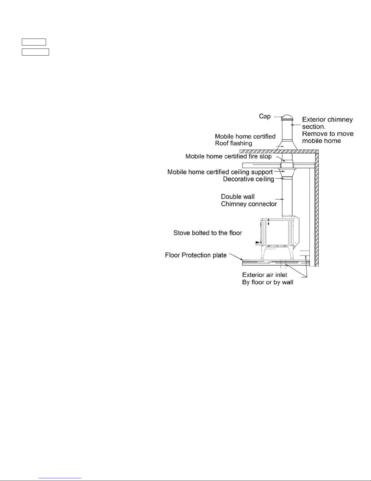
Mobile home installation
DANGER: DO NOT INSTALL IN BEDROOM.
WARNING: THE STRUCTURAL INTEGRITY OF THE MOBILE
HOME FLOOR, WALL, AND CEILING/ROOF MUST BE
MAINTAINED.
VAPOR BARRIER EFFICACITY MUST BE KEEPT IN GOOD
CONDITION.
1) Do the General stove installation from steps 1 to 11.
2) The following requirements are MANDATORY for
installation in a mobile home.
a. The stove must be fixed on the floor of
mobile home with bolt and nuts.
b. The exterior air intake must be installed.
c. The stove must be electrically-grounded to
chassis of the mobile home. In USA,
electrical grounding to the certified
terminals with 8 gauge wire and using star
washer are mandatory.
d. All of the following equipment must be
certified and approved for mobile home
installation.
3) Always keep the door closed. Open it only when add
wood or start fire.
4) To close the exterior air inlet when the stove is not in
use, a damper must be installed in the air intake pipe.
5) Don’t forget to open the damper when operate your
stove so that the smoke will not enter the house.
6) Always use certified parts for mobile home. Never use
a substitute.
Double wall chimney connector;
The chimney system;
The roof flashing;
The Storm collar;
Cap with spark arrester;
Firewall;
Chimney ceiling support;
Decorative collar.
e. If the chimney is exposed outside from a wall and
placed lower than 7 feet (213 cm) above the
ground level where the mobile home is situated, a
shield must be installed around the chimney from
the bottom to 7 feet (213 cm) high. If openings are
made into the shield, they must be less than ¾
inch (2 cm) wide and keep the distance of 4 inches
(10,2 cm) or more in order to avoid contact with
chimney.
f. The chimney must exceed at least 3 feet (91,4 cm)
from the highest point of opening made in the roof
and exceed also 2 feet from the highest point of
the roof which is 10 feet away from the chimney.
g. Be sure to seal correctly the flashing of the roof,
the firewall and the exterior air inlet with sealant.
You should also pay attention to the efficacy of
vapor barrier.
June 16, 2016 15
Page 16
Chimney installation, General steps
Use only approved chimneys, the same size as the output
collar, 6 inches in this case. The chimneys used must be tested
according to CAN/ULC S629 M87 in Canada and to UL 103
(type HT) in USA. The stove can be install with a masonry
chimney according to ULC S635, ULC S640 and UL 1777. The
masonry chimney must be equipped with a stainless steel
sleeve and meet the standards for the masonry chimney with
inner sleeve.
Provide a place to sweeping.
It is preferable, if possible, to avoid an outside chimney or built
on an exterior wall, and this is even more important for colder
areas. Outside chimneys generally have a less efficient draught.
They can even have an inverse draught because it is hard to
heat them enough so that they can reach their operating
temperature. A greater accumulation of creosote, a less efficient
draught and a lesser performance are some characteristics of
cold chimneys. Draught is proportional to the total chimney
height as well as its temperature. It is therefore possible to get a
better draught by increasing the chimney's height and by
reducing the heat loss with an insulated lining. The chimney has
to be installed with a stainless steel lining. Make sure that all
smoke pipe joints are really airtight. A leak reduces the efficiency
of the appliance and could even make its utilization dangerous.
Note: This is a general chimneys installation method.
Always refer to the manufacturer’s manual of the chimney
for a more detailed method for your chimney.
1) Determine the total length needed for your chimney.
2) Cut the holes into all floor and roof
3) If you need to cut a joist, be sure to strengthen the
adjacent joists and frame hole respecting the
minimum dimensions to be maintained between
combustible materials and the firewall. Follow the
manufacturer's instructions in the manual supplied
with the firestop. Never cut a structural beam.
4) Frame the holes in each level and attic respecting the
minimum distance recommended by the
manufacturer's manual of your chimney. Install
firestop in each level.
5) Frame the hole into the roof.
6) Install the chimney support at the ceiling where stove
is installed.
7) Stack and lock the factory built chimney section on
the support and above the roof.
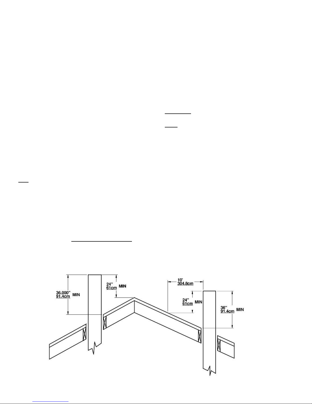
The chimney must be over 36 inches (91.4
cm) over the higher point into the roof
opening.
The chimney must also be 24 inches over
the highest point on the roof inside 10 ft (304
cm) radius around chimney.
The minimum length of chimney is 12 feet
(365.8 cm).
ATTENTION: Be sure the chimney section are locked
together and locked onto the chimney support.
NOTE: More lengthen chimney than the minimum can add
more draft and help to the good working operation of the
stove Try the minimum length first then add section if you
need more draft.
8) Put the roof flashing over the chimney and seal it with
roof caulking.
9) Nail roof flashing, and reinstall roof covering.
10) Slide the storm collar over the chimney and seal it
with high temperature caulking.
11) Lock the chimney cap and install the spark arrestor if
necessary
Note:
Chimney performance may vary.
Buildings, trees, roof line and wind conditions affect
performance, and can make backflow into the
chimney.
Chimney height may need adjustment if smoking or
overdraft occurs.
June 16, 2016 16
Page 17
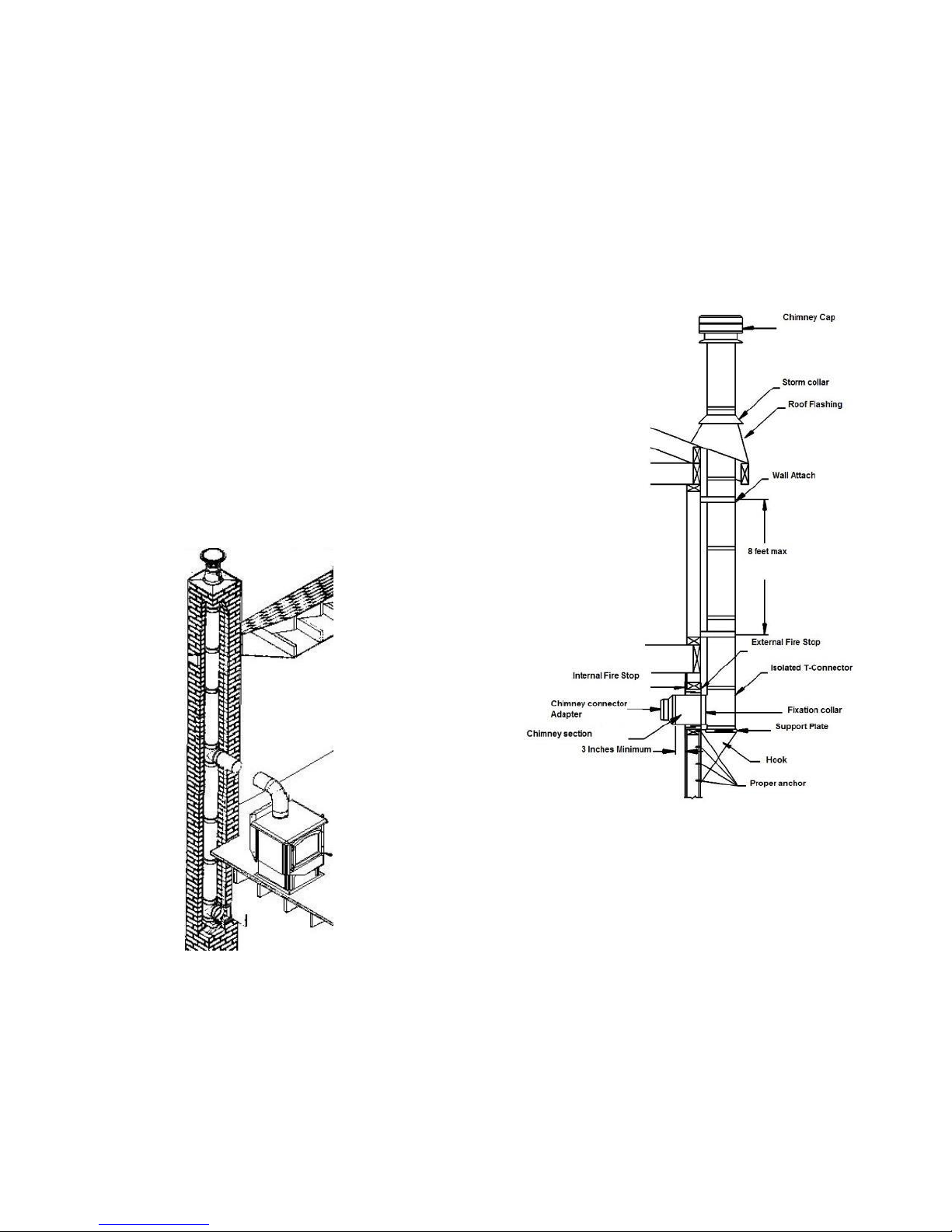
Inside Masonry Chimney, Vertical
Installation
The wood appliance must be installed in accordance with the
applicable local laws or the CAN/CSA-B365, NFPA211 (USA)
norms. Follow the chimney manufacturer’s instructions to install
the chimney.
The chimney masonry must have inside a certified metallic
sleeve cover up all the chimney height. The sleeve must be at
the same diameter of the flue collar; 6 inches (15.2 cm). The
junction between sleeve and the chimney connector must be
tight and sealed to avoid fume to go indoor.
To pass into a combustible wall between stove and the masonry
chimney. The installation method have to be safe to prevent fire.
Find the lasts information to your local authority to be sure of the
manner you have to.
To install the stove onto an abandoned masonry fireplace and
use the good condition masonry chimney the chimney must
have inside a certified metallic sleeve cover up all the chimney
height. The sleeve must be at the same diameter than the flue
collar 6 inches (15.2 cm). The junction between sleeve and the
chimney connector must be tight and sealed to avoid fume to go
indoor. Don’t forget to add a sweep opening.
Outside Vertical Installation
The wood appliance must be installed in accordance with the
applicable local laws or the CAN/CSA-B365, NFPA211 (USA)
norms. Follow the chimney manufacturer’s instructions to install
the chimney.
To pass into a combustible wall between stove and the chimney.
The installation method have to be safe to prevent fire. Find the
lasts information to your local authority to be sure of the manner
you have to. An internal fire stop and an external fire stop must
be used.
June 16, 2016 17
Page 18
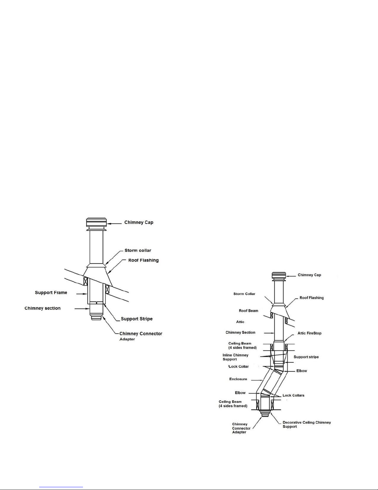
Cathedral Vertical Installation
Offset Installation
The wood appliance must be installed in accordance with the
applicable local laws or the CAN/CSA-B365, NFPA211 (USA)
norms. Follow the chimney manufacturer’s instructions to
install the chimney.
Always pass chimney between joists. If a joist need to be cut,
referring to the National Building code to know how to do it
safely to avoid structural integrity fail. Call a carpenter or a
certified Installer.
Always frame around chimney. Keep minimal clearances
written into your chimney manual.
Do not fill the gap between the fire stop and the chimney.
Nothing must be in contact with the chimney.
Always install a fire stop at each level, in a Floor, in a ceiling,
attic and in a Roof.
Always pass with a straight section into a level joist.
The chimney should be support by the cathedral roof. Build a
box around it to install ceiling support at is base.
Weight of the chimney never be allow to be support by the
stove.
The wood appliance must be installed in accordance with the
applicable local laws or the CAN/CSA-B365, NFPA211 (USA)
norms. Follow the chimney manufacturer’s instructions to
install the chimney.
Always pass chimney between joists. If a joist need to be cut,
referring to the National Building code to know how to do it
safely to avoid structural integrity fail. Call a carpenter or a
certified Installer.
Always frame around chimney. Keep minimal clearances
written into your chimney manual.
Do not fill the gap between the fire stop and the chimney.
Nothing must be in contact with the chimney.
Always install a fire stop at each level, in a Floor, in a ceiling,
attic and in a Roof.
A special fire stop need to be install into the attic. It keep
isolation and avoid the attic isolation to be in contact with the
chimney.
Always pass with a straight section into a level joist.
Chimney weight have to be support by the lower level with a
Ceiling support.
Chimney weight have to never be onto the elbows. Install a
support band to support the upper straight section over the
elbow.
Weight of the chimney never be allow to be support by the
stove.
Some restriction have to be respect regarding the maximum
angle and length of the offset. See chimney manual for this
restriction. Or local building code.
June 16, 2016 18
Page 19
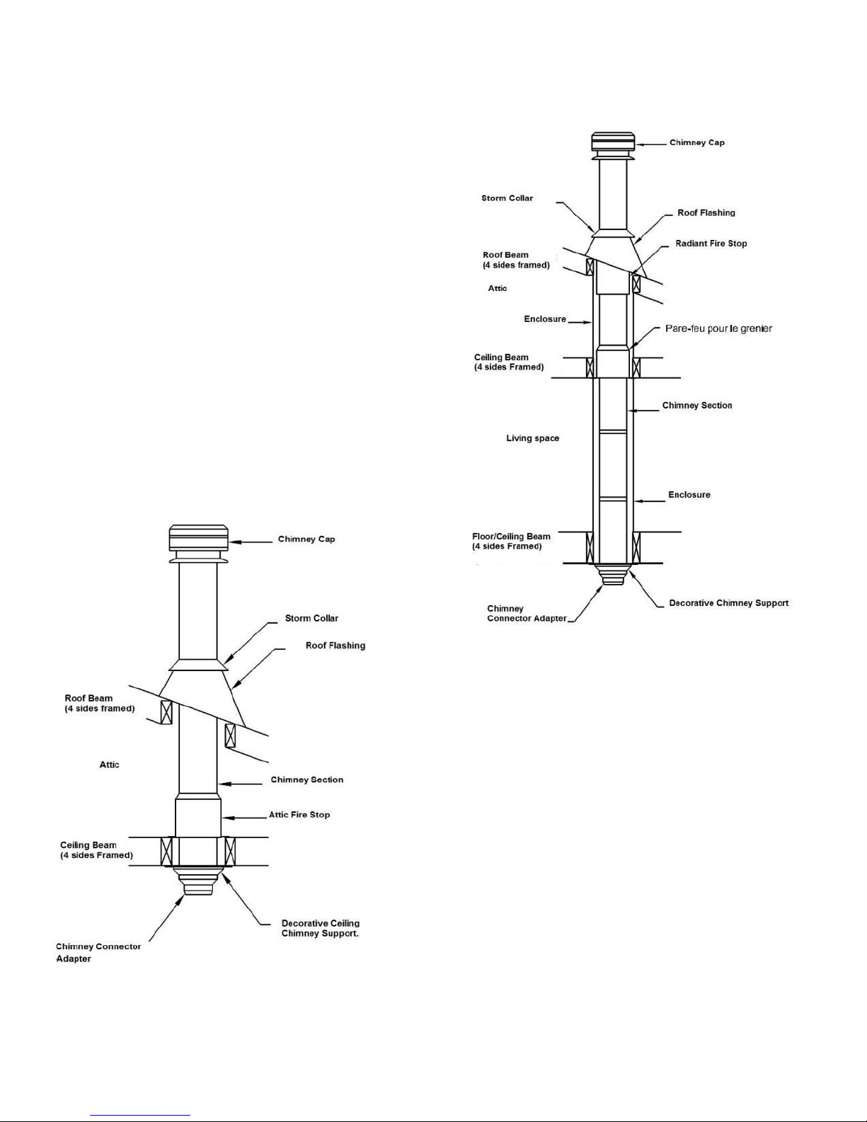
Vertical Installation
The wood appliance must be installed in accordance with the
applicable local laws or the CAN/CSA-B365, NFPA211 (USA)
norms. Follow the chimney manufacturer’s instructions to
install the chimney.
Always pass chimney between joists. If a joist need to be cut,
referring to the National Building code to know how to do it
safely to avoid structural integrity fail. Call a carpenter or a
certified Installer.
Always frame around chimney. Keep minimal clearances
written into your chimney manual.
Do not fill the gap between the fire stop and the chimney.
Nothing must be in contact with the chimney.
Always install a fire stop at each level, in a Floor, in a ceiling,
attic and in a Roof.
A special fire stop need to be install into the attic. It keep
isolation and avoid the attic isolation to be in contact with the
chimney.
Always pass with a straight section into a level joist.
Chimney weight have to be support by the lower level with a
Ceiling support.
Weight of the chimney never be allow to be support by the
stove.
June 16, 2016 19
Page 20
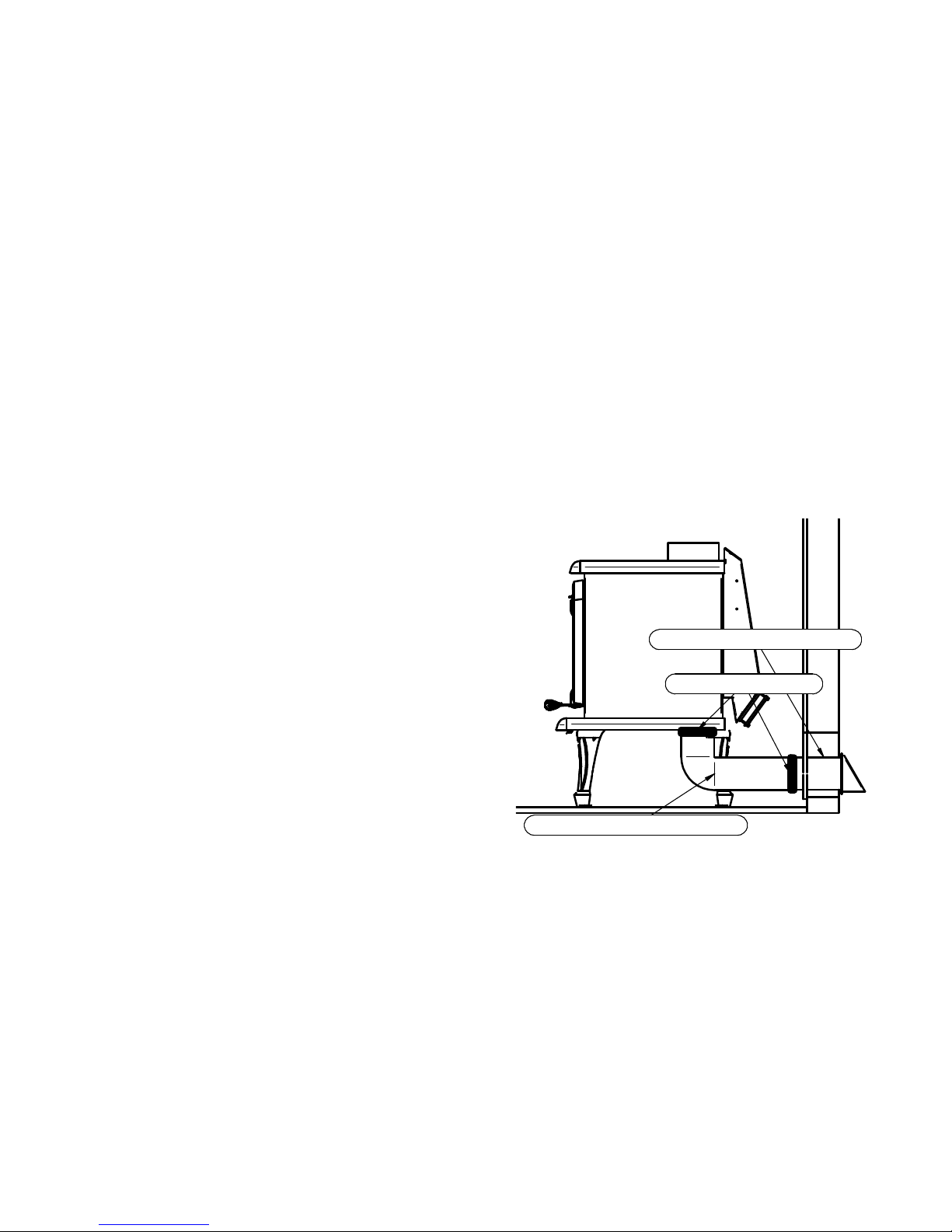
Exterior inlet with grate
Adjustable Collar
4 inches rigid or flex pipe
EXTERNAL COMBUSTION AIR
SOURCE
In conventional designed house, natural ventilation is enough
to operate the wood stove.
In some new energy saving house, natural ventilation is not
enough to good operation of your stove. To avoid reverse
circulation of smoke caused by negative pressure when turning
on some fan such as bathroom fan, cooking fan or a dryer, it is
recommended to install the external combustion air inlet.
Without the external air inlet, open a window slightly in the
room where the appliance is placed in order to avoid the
negative pressure caused by the appliances mentioned above.
A mobile home on a foundation is considered as a
conventional house.
Exterior Air Intake pipe
This appliance is certified for the mobile home installation. An
external air intake is necessary.
We recommend to use a 4 inches (10.7 cm) aluminum flexible
pipe with a dumper outside air inlet equipped with grate.
Other pipe material must be complied with ULC-S110 norms or
UL-181 Class1 norms, equipped with thermal resistant isolation
and must be corrosion resistant.
The stove must be fix to the structure when an exterior air
intake is installed.
3) Install a small rigid section inside the house and put a
damper to close the air Inlet. This damper is to reduce
the cold air circulation into the stove when it is not in
service.
4) Plug the flexible air inlet pipe onto the damper section.
5) Put a thermal resistant isolation onto the pipe if the
pipe is not isolated.
To avoid that the cold air doesn’t come in the stove, we
recommend to install a valve which closes the pipe near the
outdoor air inlet.
Air Inlet Obstruction
If the stove extinguishes after closing the door, it’s possible that
the air inlet is obstructed by something.
After a long unused period, insects or animals can build a nest
inside the air inlet.
After a storm in winter, snow can accumulate over the air inlet
and obstruct it.
Before warming season, always inspect air inlet pipe to be sure
nothing is obstructing the outside air inlet.
Installation of Air Intake Pipe
1) To install the exterior air intake pipe, find the hole
under the stove back and fold the 3 tabs outside the
Intake box. Insert the pipe into the hole and screw the
pipe using the 3 holes in the tabs. Put a generous
layer of high temperature latex caulking onto the joint
to ensure the pipe is sealed.
2) Cut the exterior wall and install Air Inlet kit following
the manufacturer installation instructions. Be sure to
seal it correctly to preserve the vapour barrier of your
house.
June 16, 2016 20
Page 21
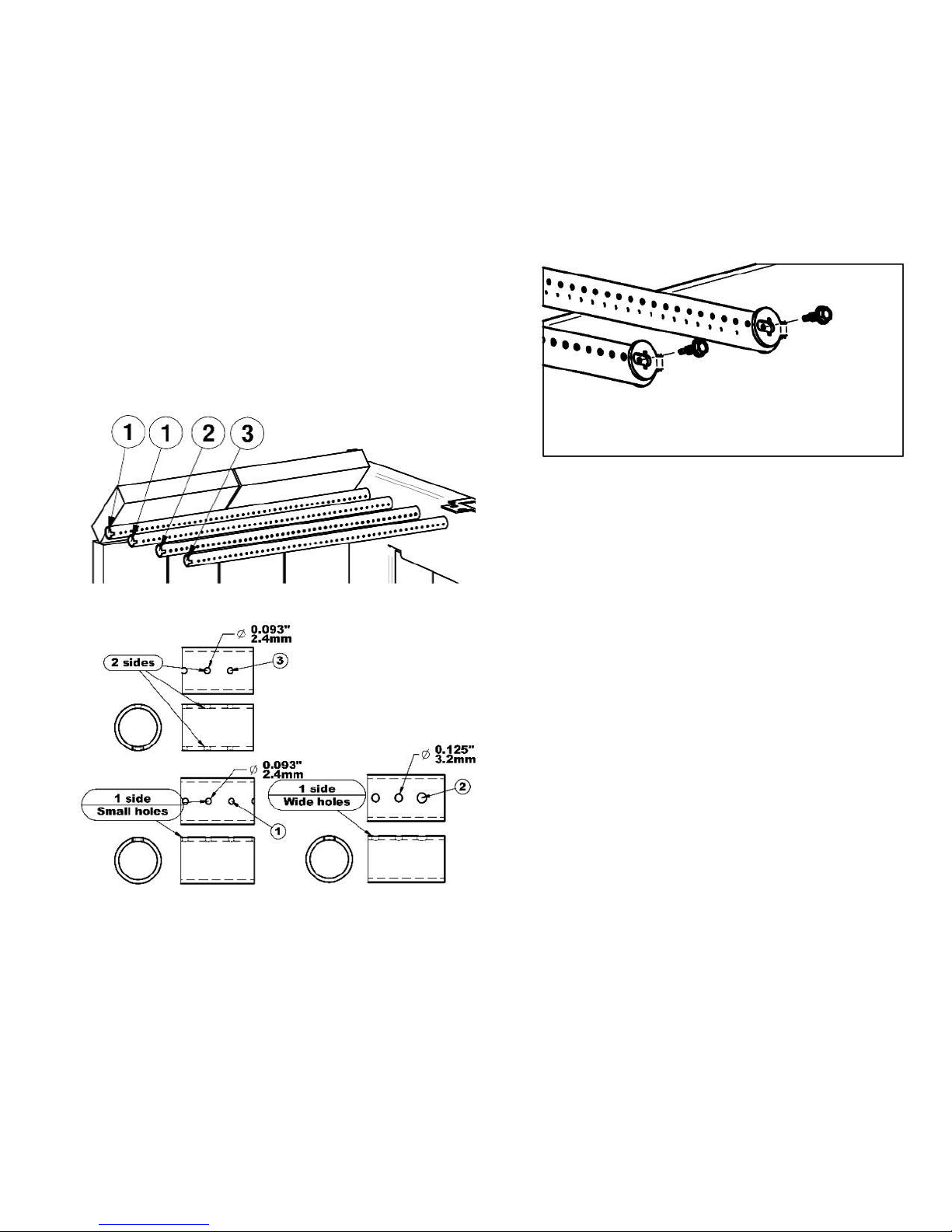
STAINLESS STEEL TUBES
REPLACEMENT
Although the tubes are in stainless steel, with extreme
temperature and conditions, the tubes are eventually corroded
and perforated by normal deterioration. They must be replaced
by a new one to ensure the performance of your stove.
Stainless steel tubes Installation
There are three type of tubes used into the stove. Two of them
are single-side perforated (1) and are in the back of the heat
chamber.
The 3rd tube from the back (2) is also single-side perforated,
but it is larger than other single-side perforated tubes (1).
The front heat chamber is covered by a double-side perforated
tube (3).
How to install tubes
1) Insert the tube into the round hole in the hot air
corridor.
2) Insert the other side in the corresponding hole of the
hot air corridor.
3) Align holes and put the screw on both sides to hold
the tube.
.
4) Install the next tube.
To remove tubes, do these steps in reverse order.
To ensure proper tubes orientation, find a notch at the end of
tube, then find a corresponding one made on the hot air
corridor.
June 16, 2016 21
Page 22
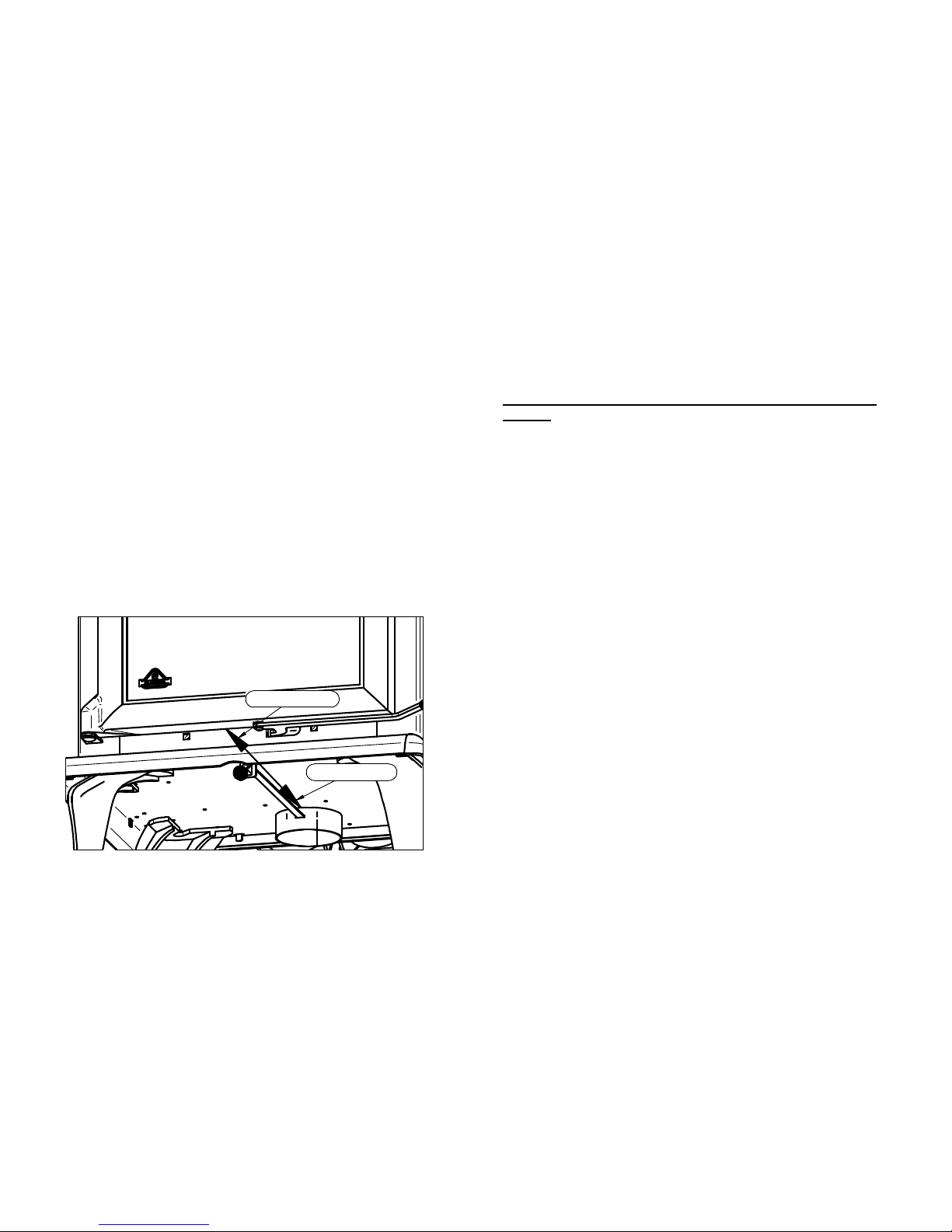
Front -Open
Back-Close
OPERATING INSTRUCTIONS
OPERATE ONLY WHEN DOOR IS CLOSED: Keeping
the door open might over fire and cause permanent
damage to the stove or a chimney fire.
IT’S RECOMMENDED TO INSTALL A CO, CO2 AND
SMOKE DETECTOR INTO THE SAME ROOM THAN
THE STOVE. The smoke detector might go on when
there is smoke leaking out.
NEVER SLAP THE DOOR.
NEVER BURN INFLAMMABLE LIQUID: Inflammable
liquid makes very intense heat and it is hard to control
the combustion. It might cause the runaway and
overheat of stove. This can consequently make
permanent damage to the stove or a chimney fire.
ALWAYS VERIFY IF THE AIR INLET IS NOT
OBTRUCTED BEFORE LIGHTNING A FIRE.
NEVER ELEVATE FIRE WITH GRATE OR ANDIRON.
ALWAYS MAKE FIRE DIRECTLY IN THE HEARTH.
Primary and secondary air admission
control
When the handle under the front tablet of the stove is pushed
completely backward, the air admission is only from the tube.
This is what we called “Secondary air admission”. On the other
hand, when the handle is pulled fully forward, the air admission
is directly from the top of the door opening and this is what we
called “Primary air Admission”.
Warning: Operating your stove with the Primary air
admission fully open for a long period of time can damage
the stove.
IT IS PROHIBITED TO MODIFY AIR ADMISSION TO
OBTAIN A BRIGHT FIRE OR FOR ANY OTHER REASON.
MODIFICATION CAN VOID GUARANTEE.
Lightning fire
After installing correctly the stove following the instruction of
the manufacturer, you are ready to light it.
1) Pull the control knob forward to let the direct air
admission in the combustion chamber.
2) Put paper and kindling wood into the combustion
chamber and light the fire in your preferred way.
3) Close the door partially keeping a slight opening.
When chimney has been hot enough, close
completely the door and let the air admission in the
horizontal position so that your fire is kindled.
4) Once you have a glowing ember, it’s time to add logs.
Follow now the instruction section on how to keep a
fire.
DO NOT OVER CHARGE THE STOVE OVER THE UPPER
BRICK.
You can control the combustion by turning up or down the
handle. The wood will burn more rapidly when more primary air
is set. Otherwise, the wood burn more slowly and more
efficiently with the handle set to secondary air.
OPERATE STOVE WITH THE PRIMARY AIR
ADMISSION FULLY OPEN FOR A LONG PERIOD OF
TIME, CAN DAMAGE THE STOVE BY OVER FIRING.
NEVER LEAVE THE STOVE UNATTENDED WHEN THE
DOOR IS SIGHTLY OPEN. ALWAYS CLOSE THE
DOOR AFTER LIGHTNING.
USE THE STOVE ALWAYS LEAVING THE DOOR
CLOSED.
NEVER USE CHEMICAL PRODUCTS OR
INFLAMMABLE LIQUID TO START THE FIRE OR
REVIVE THE FLAME.
DO NOT BURN TRASH OR ANY OTHER
INFLAMMABLE PRODUCT SUCH AS GAZOLINE,
NAPHTHA OR MOTOR OIL.
DO NOT BUILD FIRE NEAR THE DOOR GLASS.
KEEP THE INFLAMMABLE PRODUCTS AWAY FROM
THE APPLIANCE.
June 16, 2016 22
Page 23

First fire
During the first hours of operation, you must heat it gradually.
In order to allow an appropriate baking of the paint and
facilitate its adhesion with metal, do not heat the appliance with
a strong fire. It will also avoid thermal shock which could lift up
the paint or fade the color.
Make sure that the room is ventilated enough in order to
eliminate the odours and the smoke coming from the paint
during the first hours of use.
Even if this nuisance is temporary, open the windows and the
doors in order to ensure a good ventilation. This special paint is
conceived to tolerate temperatures until 1200°F (650°C).
Keep a fire
To add wood into the stove and keep a fire:
1) Pull the control knob forward and wait a few second to let
the fire adjust to the new conditions.
2) Open the door handle to the first position and wait for a
while until the fire has been adjusted.
3) Turn the door handle completely and leave the door half-
open and let the fire set up.
4) Open the door completely.
5) Move embers near the door with poker to supply it with
oxygen and make it burn completely.
6) Add firewood over the ember, keeping it away from the
glass door to avoid flame touching the ceramic glass.
ATTENTION:
DO NOT OVER CHARGE THE STOVE OVER THE
UPPER BRICK.
DO NOT BUILD A FIRE NEAR THE WINDOW.
THIS APPLIANCE IS DESIGNED TO BURN DRY
CORDWOOD. WE DON’T RECOMMEND ANY OTHER
TYPE OF WOOD.
7) Close the door slightly and let the wood burn.
8) Once the fire gets stable, close and lock the door.
9) Push the air admission knob to needed setting.
NEVER LEAVE THE STOVE UNATTENDED WHEN THE
DOOR IS SIGHTLY OPEN. ALWAYS CLOSE THE DOOR
AFTER ADDING A LOAD.
DO NOT USE ANY INFLAMMABLE LIQUID TO REKINDLE
THE FIRE.
Fan Control
The optional switch on the snap disc box is only to turn on and
off the fan.
When it’s ON, the snap disc will start at the moment when the
temperature of ventilation box gets 120 Fahrenheit (49 °
Celsius).
In OFF Position, the fan is turned off and it doesn’t start.
If the switch is not installed, the operation is the same as in ON
position.
NEVER ROUTE THE ELECTRIC WIRE OF FANS IN FRONT
OR UNDER APPLIANCE.
Fuel Selection
This heater is designed to burn only firewood. Using firewood
dried properly results in higher efficiencies and lower emissions
of pollutant compared with using softwood or fresh wood.
Moisture Meter Information
Firewood is ready to use at 10‐25% moisture content.
Fresh cut logs can have a moisture content of 80% or more,
depending on species. During the drying process, wood might
shrink, split, twist or change shape. In general, wood must be
dried before use. Air drying, i.e. ‘seasoning’ is the most
common method used for cordwood.
Season wood outdoors through the summer for at least 6
months before burning it. Properly seasoned wood is darker,
has cracks at the ends, and sounds hollow when smacked
against another piece of wood.
In most parts in the North America, the minimum moisture
content that can be generally obtained in air drying is about 12
to 15 percent.
June 16, 2016 23
Page 24

Things not to burn
1) Garbage;
2) Lawn clippings or yard waste;
3) Materials containing rubber, including tires;
4) Materials containing plastic;
5) Waste containing petroleum products, paints or paint
thinners, or asphalt products;
6) Materials containing asbestos;
7) Construction or demolition debris;
8) Railroad ties or pressure-treated wood;
9) Manure or animal remains;
10) Salt water driftwood or other previously salt water
saturated materials;
11) Unseasoned wood;
12) Paper products, cardboard, plywood, or particleboard.
The prohibition against burning these materials does not
prohibit the use of fire starters made from paper, cardboard,
saw dust, wax and similar substances for the purpose of
starting a fire in an affected wood heater. Burning these
materials may result in release of toxic fumes or render the
heater ineffective and cause smoke.
Wood storage
The cordwood must be store into dry place, away from bad
weather.
It should not be stored under or near the stove.
If any wood is stored next to the stove, it must respect the
minimum clearances to avoid self-ignition temperature.
10 inches (25.4 cm) behind
20 inches (50.8 cm) beside
48 inches (122 cm) in front
Draft
Draft is the force which moves air from the appliance up
through the chimney. The amount of draft in your chimney
depends on its length, local geography, nearby obstructions
and other factors. Too much draft may cause excessive
temperatures in the appliance and may damage the appliance.
An uncontrollable burn or excessive temperature indicates
excessive draft.
Insufficient draft will cause the appliance to leak smoke into the
room through appliance and chimney connector joints.’
Creosote Formation
When wood is burning slowly, it produces tar and other organic
vapors, which are combined with expelled moisture to form
creosote. The creosote vapor condenses in the relatively cool
chimney flue of a slow-burning fire. As a result, creosote
residue accumulates on the flue lining and this creosote makes
an extremely hot fire when ignited.
MAINTENANCE
Ash Removal
The wood burning doesn’t transform the wood into combustion
gas completely. It makes some residue called ash and it must
be removed from the combustion chamber to help oxygen
circulation.
The ash have to be removed periodically every 2 or 3 days
during heavy warming period. Never had excessive
accumulation into the combustion chamber because it can
reduce performances of your stove by diminish the air
circulation between logs.
When ashes get 3 to 4 inches deep in your firebox, and when
the fire has burn down and cooled, remove excess ashes.
Leave an ash bed approximately 1 inch deep on the firebox
bottom to help maintain a hot charcoal bed.
The best time to remove ash is after a long warming period like
morning when the stove is relatively cold enough to manipulate
ash and the chimney is still hot. The hot chimney draft will
vacuum the dust inside the stove.
To clean ash from the combustion chamber, you must have the
following tool.
Ash shovel;
Ash brush;
A metal bucket with airtight lid.
Some embers is mix with ash and still lit a few hours or a few
days. It is very important that the metal lid was airtight. The
bucket must be put on a non-combustible tile or brick.
Ash Disposal
Some embers mixed with ash can still be lit. If embers have
enough oxygen, they can still stay lit some hours and even a
few days.
It’s mandatory to store ash pending disposal:
Into a metal container with an airtight metal lid
correctly closed
Outside the house on a non-combustible material
such as gravels, concrete and bricks.
Far enough any combustible material.
Far enough any inflammable liquid and vapor.
If the ash are disposed of by burial in soil or otherwise locally
dispersed, they should be retained in the closed container until
all cinders have thoroughly cooled.
NEVER PUT TRASH INTO THE ASH CONTAINER.
The chimney connector and chimney should be inspected at
least once a week during the first month to determine if a
creosote buildup has occurred and to see how often you have
to sweep it. Warmer your fire is, less creosote buildup occurs.
Contact your local fire authority to know how to handle a
chimney fire.
June 16, 2016 24
Page 25

Chimney Inspection
Wood moisture, a type of wood, the combustion quality are the
factors that can influence creosote buildup speed into the
chimney and chimney connector.
The chimney and the chimney connector must be inspected at
least one every two month during the warming season or more
depending on your installation. You can call a Chimney
sweeper to evaluate the creosote formation or you can do it
yourself. Extinguish the wood stove, wait for cool down then
unscrew the chimney connector and inspect the chimney
connector and the factory build chimney with a spot light to see
if a creosote buildup as occurred. For a masonry chimney,
insert a mirror in the cleanout opening at the bottom on a bright
day. For an outdoor factory build chimney, open the cap at the
bottom of chimney.
If there is 1/8 inches (3 mm) or more creosote buildup, smaller
apparent diameter or if you cannot see the chimney cap, it’s a
sign to sweep your chimney connector and your chimney to
remove creosote.
Chimney Sweeping
Chimney Sweeping needs a special tool such as fiberglass rod,
an adapted diameter brush and a rope.
Sweeping chimney also requires to climb on the roof to remove
the chimney cap and sometime even a very high chimney
section too.
We recommend to call a Professional chimney Sweeper
certified by APC in Quebec, the WETT in the rest of Canada or
by NFI in United States.
Door maintenance
The door is the mobile element that needs a special attention.
Its tightness is essential. One of the first signs of wear braided
fiberglass rope is the white soot sticking on the glass where the
air leaks.
Air tight Adjustment
If the braided fiberglass rope still seems good enough but little
flattened, it needs probably to be tighten.
Door adjustment (right side)
This side adjustment can be done with the screw under the
door near the hook hole.
1) Unlock and open the door.
2) With a square screwdriver, turn clockwise the
adjustment screw a quarter turn.
3) Put a piece of paper between the frontage of stove
and braided fiberglass rope. Close and lock the door.
4) If the paper slides easily when you pull it, repeat steps
1 to 3 again.
5) If the screws are tightened but the piece of paper
comes off easily, the braided fiberglass rope must be
changed.
Cleaning up glass
To clean the glasses, J.A. Roby Inc. recommends using
products sold for this purpose or an oven cleaner avoiding
touching paint part.
Avoid cleaning with abrasives and cleaning the hot glass.
Cleaning hot glass can cause a thermal shock and can break
the glass.
Uninstalling and installing door
To uninstall, keep the lower hinge tighten.
1) Open the door.
2) Lift the door to remove the lower hinge.
3) Tilt the door to remove the upper hinge.
Installing the door.
1) Insert the upper hinge
2) Align the lower hinge.
3) Place the door on the lower hinge.
4) Close the door.
June 16, 2016 25
Page 26

Replacing broken glass
WARNING: NEVER OPERATE STOVE WHEN THE GLASS
IS BROKEN OR CRACKED.
DO NOT SLAP THE DOOR.
NEVER BUILD FIRE NEAR THE GLASS.
NEVER PUT WATER ONTO THE GLASS TO AVOID A
THERMAL SHOCK.
Replace only with a 4mm ceramic glass with the right shape.
DO NOT USE SUBTITUTE.
Steps to replace broken glass
1) Loosen partially the screws retaining the four glass
supports.
2) Remove the broken glass and all pieces of broken
glass and clean the door.
3) There is a fiberglass rope for sealing. If not, you need
to install it. Stick the flat fiberglass rope around the
glass without pulling it excessively. A sticking side is
already on the flat rope.
4) Install the new glass and put the lower support first
and gently tighten screw. If screws are tighten too
much, it makes pressure points and it might break the
glass when it gets hot.
5) Install the top support and gently tighten screw.
6) Verify if all the screws are tightened properly.
If you cannot replace glass with the door in place, you may
have to remove the door. To do so, follow the instruction of this
manual.
Fiberglass rope installation
1) Put a high temperature latex inside the clean groove
to glue the fiberglass rope.
2) Starting at the lower corner near the hinge put
fiberglass rope into the groove without giving any
tension
3) Align the two fiberglass rope ends perpendicularly and
put some high temperature latex in between.
4) Let dry the high temperature latex for at least 48
hours. Put the door back on the hinge and readjust
the tightness.
WHAT TO DO IN CASE OF
CHIMNEY FIRE
CONTACT YOUR LOCAL AUTHORITY TO KNOW WHAT TO
DO IN CASE OF CHIMNEY FIRE. AND BE SURE TO KNOW
PROCEDURE IN CASE OF CHIMNEY FIRE.
1. Close all door, the air inlet and the damper.
2. Water the combustible materials around the stove.
3. Trigger alarm and leave the house, if necessary, and call
the Fire department.
4. Never touch the chimney while is burning.
Do not use the chimney before an inspection or repair
necessary.
.
Fiberglass rope replacement
When it is impossible to adjust the door because of the
flattened fiberglass rope, it is the time to change it. If the rope
is damaged, you also have to replace it.
Use a ½ inches (12.7mm) braided fiberglass rope.
To install the new fiberglass rope, we recommend to detach
the door from the stove. Please see the pertinent section in this
manual.
Fiberglass rope preparation
1) Take the end of the fiberglass rope and push fiber
inside.
2) Add little touch of high temperature latex inside the
end of the fiber glass rope to make a clean end.
3) Remove old fiberglass rope and clean the groove.
4) Starting at the lower corner near the hinge put the
fiberglass rope into the grove without giving any
tension to verify the length of the rope.
5) Cut the rope in more than ½ inches and repeat the
step 1 and 2.
June 16, 2016 26
Page 27
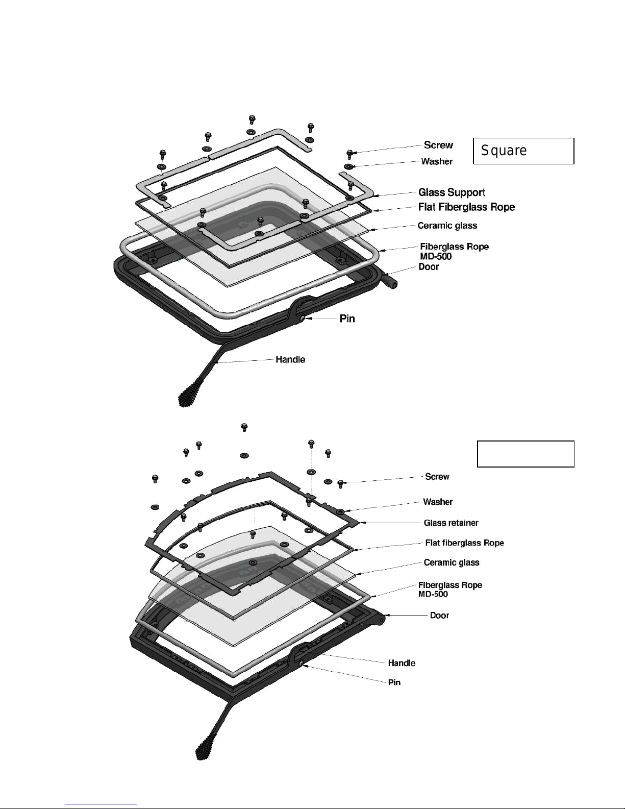
Square door
Arc door
APPENDIX 1
Exploded diagram of door
June 16, 2016 27
Page 28
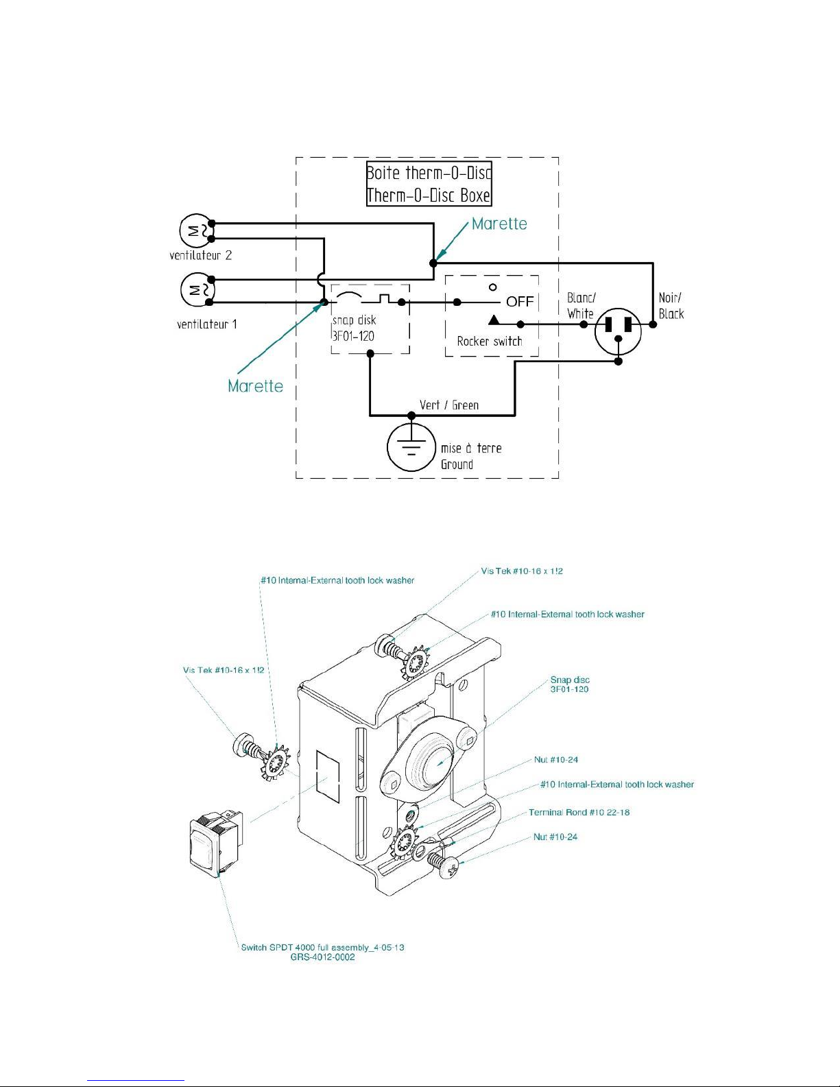
APPENDIX 2
Fans electric wiring diagram
June 16, 2016 28
Page 29

APPENDIX 3
Parts that can be replaced
Bricks
Door glass
Spring Handle
Stove Door with handle
Fans
Flat fiber glass rope (around glass)
Round fiberglass rope
Ash Plug
Slotted Brick Washer
Call your stove seller representative to order parts.
June 16, 2016 29
Page 30
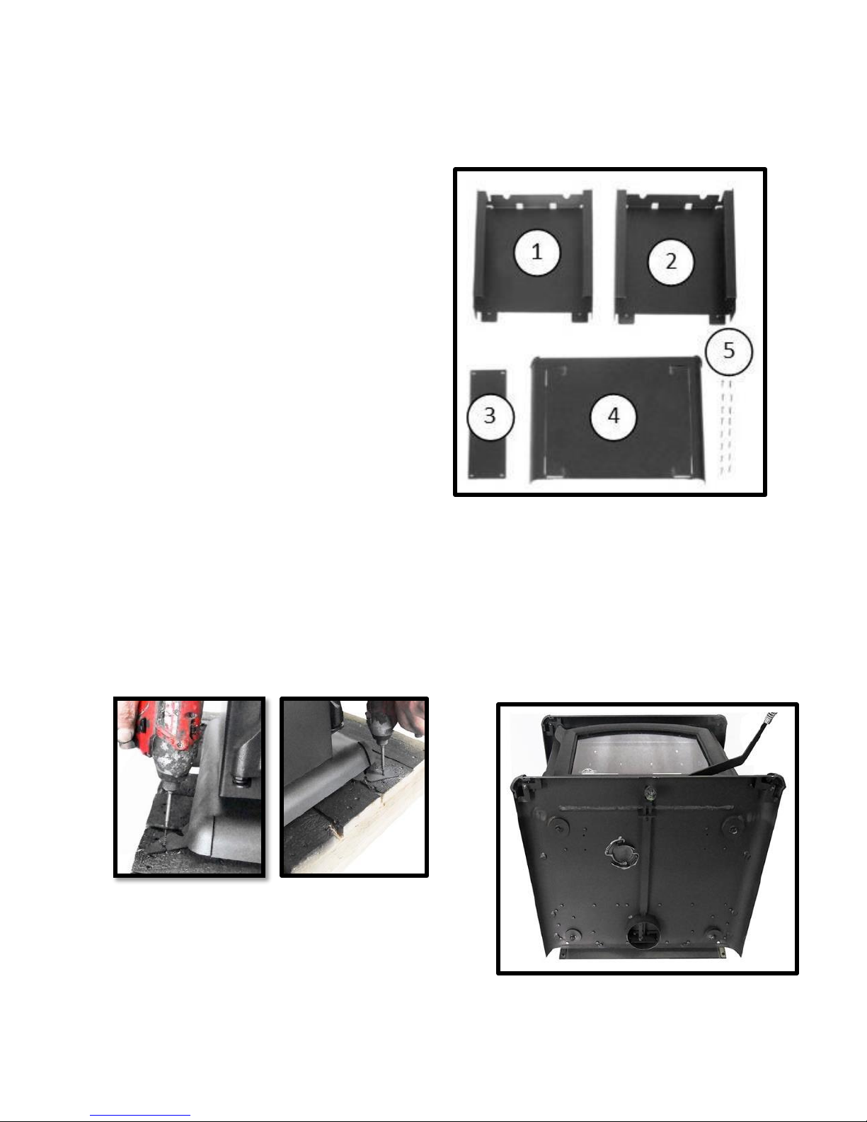
The pedestal consists of 5 components.
2. Put the stove on its back.
1. Detach stove from the skids.
ANNEXE 4
Pedestal installation
1) Left Side
2) Right Side
3) Reinforcing plate
4) Base
5) screws
June 16, 2016 30
Page 31
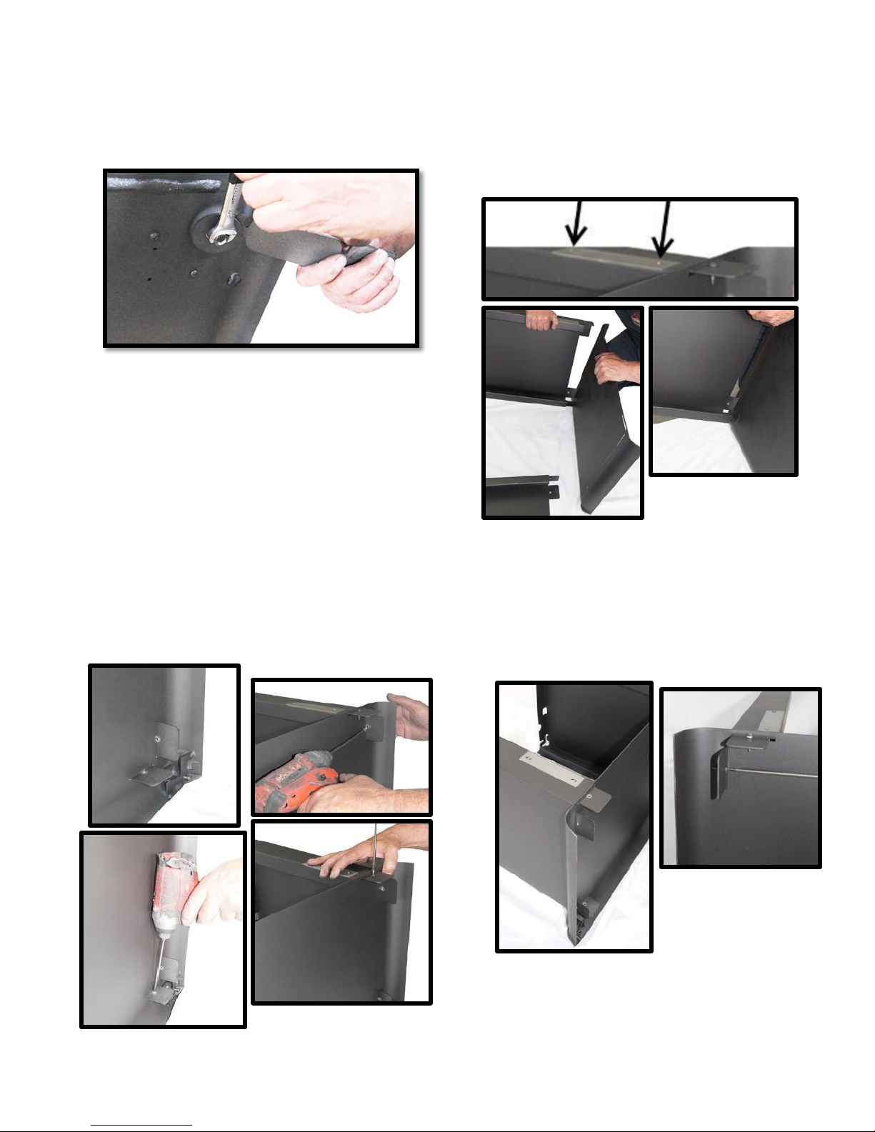
5. When you insert the left side part,
4. Insert the left side part on the base.
6. Install the right side part. Make
pedestal.
3. Detach skid anchor. We recommend
you to ask for help to avoid accident.
Be careful not to insure yourself.
Note : To distinguish the left side part from
the right side part, find the holes for the
reinforcing plate on the non-rounded side of
the base part, at the back of the pedestal.
several sections for fixing will be sticking
out through the base part. Place screws in
the holes of these sections.
sure that the sections for fixing the
reinforcing plate is on the back of the
June 16, 2016 31
Page 32
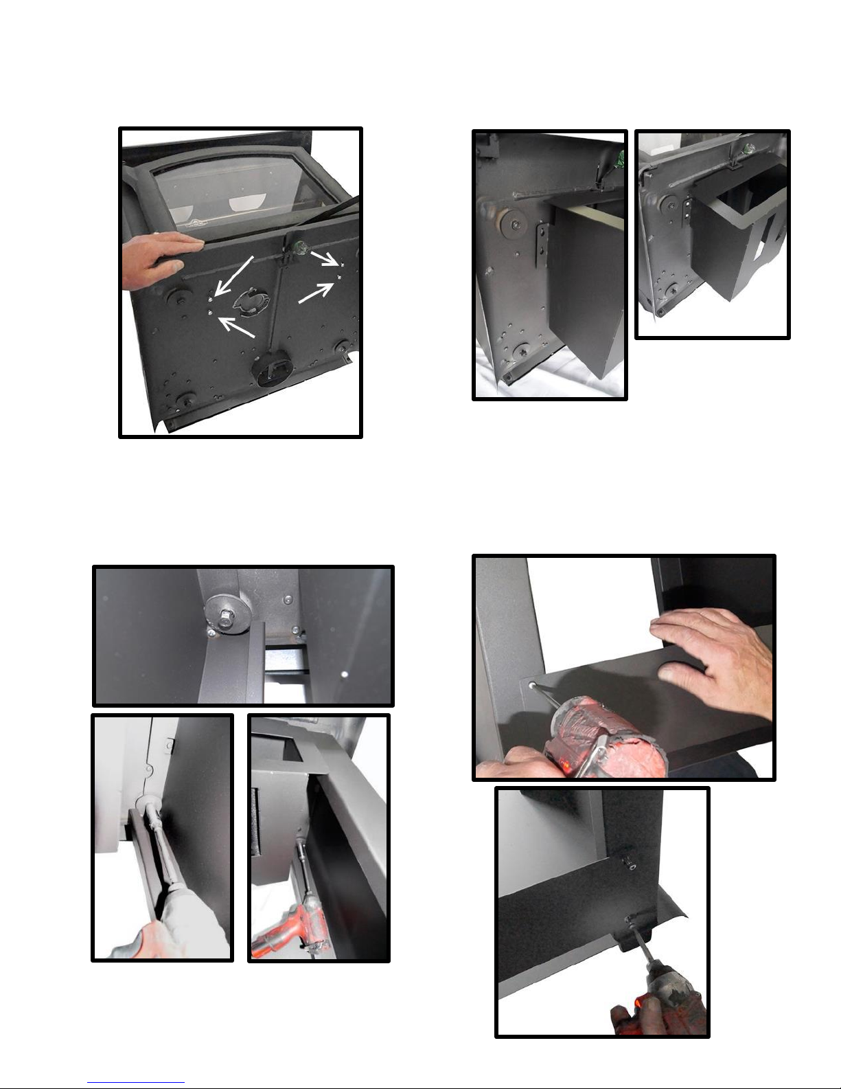
8. Install the ashtray holder by screwing
7. Remove the screws for the
ashtray holder.
10. Install the reinforcing part at the back
of pedestal. Let the stove stand on the
pedestal.
9. Open the pedestal slightly and
tack the washers on both sides.
Attach it with nuts.
with the holes for this purpose.
June 16, 2016 32
Page 33
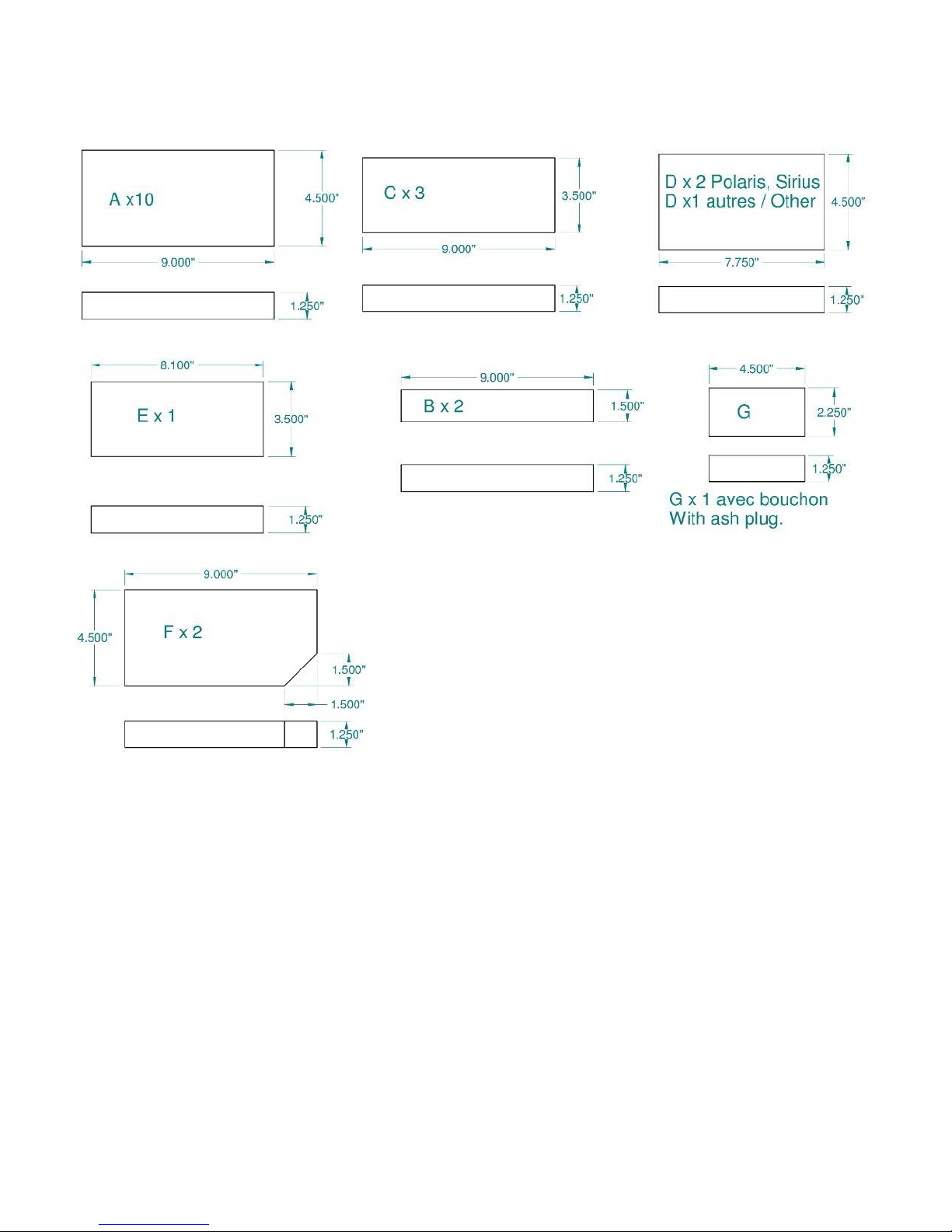
APPENDIX 5
Dimension and quantity of bricks
June 16, 2016 33
Page 34
WARRANTY DESCRIPTION
100%
50% current retail price
Ashtray, handles, doors and cast iron legs
Life
Combustion chamber
5 years
From 5 years to life
Secondary air tubes
5 years
Heat exchanger
2 years
From 2 years to life
Switches, thermodisc, wiring and electrical components, standard blowers and rheostat
2 years
Tempered glass, optional blower and gasketing
1 year
Ceramic glass (thermal breakage only1)
1 year
Replacement parts (with proof of purchase)
90 days
STOVES & FIREPLACES
J. A. ROBY LIMITED LIFE WARRANTY
WOOD BURNING STOVES & FIREPLACES
J. A. ROBY’s warranty only applies to original buyer and is non-transferable. This warranty covers brand new products only, which have not been
altered, modified nor repaired since shipment from factory. The products covered by this warranty must be manufactured after review date indicated
at the bottom of page. Proof of purchase (dated bill of sale), model name and serial number must be supplied when making any warranty claim to your
J. A. ROBY dealer. Registered your warranty is not required.
The appliance must be installed by an authorized service technician or contractor. Installation must be done in accordance with the installation
instructions included with the product and all local and national building and fire codes. Any service call related to an improper installation is not
covered by this warranty. This warranty applies to normal residential use only. This limited warranty does not cover damages caused by misuse,
improper installation, lack of maintenance, accident during transportation, alterations, power failure, venting problems, downdrafts, abuse, over firing
or neglect. Operating the appliance on high for extended periods of time is neglect. Any defect or damage caused by the use of unauthorized parts or
others than original parts void this warranty.
This limited warranty does not cover any scratch, corrosion, warping or discoloration. The manufacturer may require that defective products be returned
and/or that digital pictures be provided to support the claim. Returned products are to be shipped prepaid to the manufacturer for investigation. If a
product is found to be defective, the manufacturer will repair or replace such defect. The transportation fees to ship back the product to the purchaser
will be paid by the manufacturer2. The external labour fees related to warranty repair are not covered. The manufacturer may at its discretion, decide
to repair or replace any part or unit after inspection and investigation of the defect. The manufacturer may at its discretion, fully discharge all obligations
with respect to this warranty by refunding to the original warranted purchaser the wholesale price of any warranted but defective part (s). The
manufacturer shall not in no event be liable for any special, indirect or consequential damages of any nature whatsoever which exceeds the original
purchase price of the product. All parts replaced under this limited life warranty are subject to a single claim.
Any damage to the appliance, combustion chamber, heat exchanger, enameled cast iron cooking plate or other components due to water, weather
damage, long periods of dampness, condensation, damaging chemical or cleaner will not be the responsibility of J. A. ROBY. Failure of any components
which is attributed to poor maintenance, is not warrantable and will not be covered by this policy. J.A. ROBY neither assumes, nor authorizes any
third party to assume, on its behalf, any other liabilities with respect to the sale of this product.
The manufacture of your new appliance and the following materials are warranted against defects as mentioned below:
Due to on-doing product improvements, all specifications and design are subject to change without prior notice.
Before shipping your unit or defective component to our plant, you must obtain from J. A. ROBY dealer an authorization number. Any
merchandise shipped to our plant without authorization will be refused automatically and returned to sender.
1= Digital pictures required 2= Shipping cost are not covered outside CANADA Review oct. 2014
June 16, 2016 34
 Loading...