


ARMOR SENTINEL
PTZ CAMERA
USER’S MANUAL
Series
SAB-8237
OSD V1.0

2
SAFETY WARNING
Before using this product, be sure to read the installation instructions
carefully, and to remove the protective lining from the unit before
proceeding with settings.
In case of failure, be sure to turn off the power or remove the power supply
before contacting service personnel.
Do not disassemble this product without the assistance of a skilled technician.
This product consumes
DC12V/1.2A power. Do not use other non-specified
power supply.
Keep exposed portion of wires and plugs duly insulated.
Do not manually position the pan/tilt module at all times.
Do not point this camera to the direst sun light or any shining object at all
times to prevent possible damages.
To avoid potential failure, do no situate this product in any place subject to
excessive vibration, humidity or dust pollution.
Thank your for the purchase of our product.
In order to make good use of this product, please read this user’s manual carefully.
Be familiar with all operating procedures, in order to use this product correctly.
Please keep this user’s manual for future reference.
The information contained in this document is subject to change without notice.

3
Safety Warning
…………………..…………………………..………..…... 3
Introduction…………………………..………………………..………..……. 5
Characteristics………………………..………………………..………..……. 5
Operating instructions
Accessories………………………………..…………………..……………… 6
Installation……………………………………….………..……………..…… 7
Connection………………………………………………..……………..…… 9
Basic setting………………………………………….……………...……….. 10
No. setting……………………………………….……………...…………. 12
Infrared remote control……………………………….…………….......…….. 13
About the infrared remote control ………………………………….......……. 13
Operation
Infrared remote control mode………………………………………………… 14
RS-485 control mode… ……………………………………………………… 18
Remarks
Maintenance & cleaning ……………………………………………………... 18
Troubleshooting ……………………………………………………………… 19
Optional accessories………………………………………………………….
20
Lens internal setting………………………………………….………..……..
22
Table of Contents

4
This is a smart remote control color camera of the latest design. The camera comes
with features not available in other conventional cameras. Its programmable setting and
the wireless remote controller allow the camera to perform with a full range of viewing
angles.
Featuring SONY COLOR CCD , the high image quality and low luminance along with
its exceptional design has earned the product many certifications and patents, such as CE,
FCC, and IP66..
Compact and aesthetic, this all in one, 360° remote-controlled unit, with the certified
blastproof dome cover and the rigid aluminum alloy IP66 waterproof casing make the
product as top of the line.
This product has earned various patents for its exclusive design. It is safe to use.
The certified blastproof and reinforced-coated spherical hood and the rigid
aluminum alloy waterproof casing makes it apt for both indoors and outdoors.
The silent and step motor, the only built-in sophisticated bearing and the built-in
overload protection extends the service life of the product.
With the patented smart universal turntable and PLC or the automated turntable on
the remote control, the camera is free to tilt in 90° and make a 360° panorama.
Monitoring ranges, angle, stay time and rotation speed are all programmable.
A total of 128 points can be set for monitoring with smart auto tracking.
Built-in 2 sets of auto tracking alarm for engagement with OSD functions.
Camera with standard encoding of up to 128 units.
The built-in twin-filter switch OLPF Removable features high resolution and low
luminance and it comes with a 230-time high-efficiency zoom lens for convenient
observation.
With the humane infrared remote control that features digital selector, function key
and turntable among other keys.
Available with wireless remote control and RS-485 system control.
With a wide variety of peripherals available for expansion, integrated control in he
system is there for you. (See Pages 20, 21)
Introduction
Characteristics

5
Accessories
4
Infrared receiver
5
No. 4 AAA
Batteries
6
Infrared remote
control
9
User’s manual
8 Securing screws
7 Tool to open the
upper lid
3 Power supply
DC12V/1.2A
1
Blastproof camera
2
Control connector
(in camera)

6
Before the product is duly installed and set, do not turn power on or
turn the lens with your hands.
Step 1
Appearance
A. Upper lid
B. Base
C. Securing hole
D. Waterproof washer Securing screw
E. Waterproof connector (Do not open)
F. Washer
Step 2
With7, turn to open all the waterproof securing screws
counterclockwise before carefully removing the spherical
hood and the waterproof washer.
Do not scratch the spherical hood or touch the parts.
Step 3
Carefully remove all the lens caps upward.
To keep the parts from experimenting damage, be sure
not to tear them. For the sake of sound results, after
removing them, do not touch the lens with your hands or
other objects and do not turn the lens or remove other
parts. Doing so might cause damage.
Step 4
System mode and number setting
(Please refer to Basic Settings on Page 10).
Installation
C
A
B E
F
D
987654321
ON

7
Unit:mm
Step 5
Carefully load the spherical hood and the waterproof
washer back and tighten all the waterproof screws
clockwise using
7.
To keep both items waterproof, be
sure they are properly tightened.
Do not scratch the spherical hood or touch the parts.
Step 6
Secure the camera in an appropriate position using
8
and
keep the size of the securing hole as indicated in the
drawing. Successful setting and installation may be
achieved by following the step given above.
Before securing, check if the installation structure is to
hold the weight of this unit.
Remarks:
After turning on the power for the first time or resuming the power, the camera will
rotate once for resetting and this is normal.
If you do not have the auto rotation or there is noise or in other cases, turn the power
off and check.
If you fail to locate the problem, contact the local dealer for help.
Keep all original accessories for future maintenance.

8
Wire specification:
Power cord: 18AWG-2C
Video cord: 5C2V(5CFB) 168
Alarm cord: 24AWG-4C
Infrared receiver insulation wire: 24AWG-3C
RS-485 insulation twin-line control cord: 24AWG-1P
The above specification suggests minimum requirements. For the sake of quality,
thickened wires would be necessary for long-distance transmission.
Reference distance for transmission 200 meters.
Connection
Infrared remote
control
Monitor
Camera
Infrared receiver
AC IN
(Dark gray)
RS-485(A)
Video output
RS-485(B)
SMK-054 / SMK-054IR
Multi-purpose Keyboard
(Otherwise available)
(Brown
)
ON / OFF
Max. 300mA
N.C
COM
N.O
I/P DC5~12V
Max. 300mA
(Mesh)
(Grey)
(White)
Drive
(Otherwise available)
Input 1 (Yellow)
Input 2 (White)
Shared (Black)

9
1 2 3 4 5 6 7 8 9
ON
G. Camera jack
H. System mode & unit No. setting
Be sure to set the system mode first and then the unit No., to do so, turn the switch up
or down.
Before a new setting, be sure to turn the power off for at least 5 seconds. Duration of
power supply after setting is given as follows. Only when the power supply time is set,
the system mode or the unit No. would then be updated.
H.1 System mode setting:
1 ~ 6 Setting of communication control code
7 Setting of installation manner
8 Factory setting
9 No action
10 Enter into system mode setting
H.1.2 Before setting the system mode, be sure to turn off the power supply for at least 5
seconds.
H.1.3 To set the system mode, turn Switch 10 down.
H.1.4 Setting the compatible communication control code:
In the infrared remote control mode that does not need any setting, this step can
be ignored.
For the RS-485 control mode, please select the following control codes. Only
one of 1~6 can be selected and pressed down.
Switch 1 DYNA9600
(DYNACOLOR Rate 9600)
(Set by the maker)
Switch 2 PELCOP9600
(PELCO-P Rate 9600)
Switch 3 PELCOP4800
(PELCO-P Rate 4800)
Switch 4 PELCOD2400
(PELCO-D Rate 2400)
Switch 5 LILIN9600
(LILIN Rate 9600)
Switch 6 Unoccupied code
Basic Setting
GND
VIDEO
+12V
IR-S
485-B
485-A
IR-P
A-O/P
A-I/P1
A-I/P2
H G
987654321
ON

10
For compatible codes, you may enter into MENUPROTOCOL with the
remote control for the selection of a menu. To set a MENU, you may ignore
this step.
To use the keyboard of make DVR or other controls, you will not be able to
change the control code in MENU.
H.1.5 Installation:
Turn switch 7 up for embedded and wall mounting. (Set by the maker)
Turn switch 7 down for desktop installation.
This will change the direction at the same time and consult with the dealer for
vertical and horizontal orientations of image.
H.1.6 Set by the maker:
Turning switch 8 up will not change user’s setting. (Set by the maker)
Turning switch 8 down will clear all functions set by the user and restore the
values set by the maker, which comes with 2 groups of present points.
H.1.7After setting per system mode, it takes 15 seconds to have the power on with
automated updating of the system. When the power is on, a setting message
readingE:0 C:U DYNA9600will appear under the screen. When successful,
turn the power off and then turn all the switches up before setting the unit No. as
indicated in the following step.
For factory settings, it takes 30 seconds to have the power on with automated
updating of the system.
Setting message
E:0 No change in setting
E:1 Clear setting and restore factory setting.
C:U Setting for embedded and wall mounting
C:D Setting for desktop installation
DYNA9600 Communication formatting code, types 1~6 may come with
different display per setting.
H.2 Unit No. setting:
1 ~ 7 Unit No. setting (Please refer to unit No. setting table)
8 ~10 No action
Single unit mode: No. 0 (In the infrared remote control mode, it is unnecessary to
input the unit No. for direct control or setting)
Multiple unit mode: No .001 ~ 127 (It is necessary to input the unit No. for the
control or setting, otherwise no operation would be successful.)
H.3 After successful setting, it takes 10 seconds to have the power on and the
automatic positioning ready before operation.
11
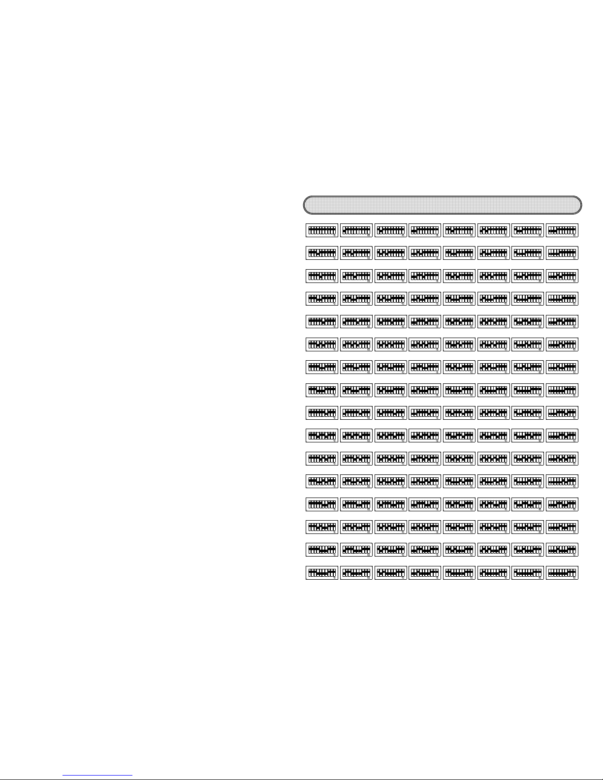
Set camera ID number
98ON21
ON
3
4 5 6 7 8 9
6543 987
21 543
2
ON
ON
1
3 4 5
987
8 97
41 32 85 76 9
442 31
ON
ON
2 31
ON
8
4
98
31 2 6 754
3
ON
2
ON
1
4 5 76
3398 21
8
9
ON
ON
1
2
7654 98
7
4 5 6 8 9
6
6
7721 3 4 5 6
ON
1ON2 6543
8
9 1 2
7
000
442 31
ON
ON
1
32
86 75 9
85 76 9
8
8
4
1 32 5 76
4ON2 31ON6 75
9 1 32
9ON2 31
ON
4 5 76 8 9
6 75
6 75 9 2 31ON6 754 98 32
ON
1
4 5 76 38 9
ON
1
2 74 5 6 8 9 671ON2 6543 98 21ON6543 987 2
ON
1
3 4 5 8 9
1ON6 75 9 2 31ON6 754 98 32
ON
1
4 5 76 8 9 3
ON
1
2 74 5 6 8 9 71ON2 6543 98
4
ON
1
32 85 76 9 842 31
ON
9
9
885 76
5 7699
442 31
ON
ON
2 31
ON
886 75
6 7599
8
8
8
8
ON
4
4
ON
2 31
1
32
6 75
5
76
4
4
ON
2 31
2 31
6 75
8
6 75
6 7599
842 31 6 75 9 2 31
8
844
ON
1
32
ON
1
32
5 76
5 76
ON
9
9
ON
1
32
ON
1
32
ON
6 754 98 321 4 5 76
987654321
ON
4
ON
1
32 85 76 9 4
ON
1
32 85 76 9 8423
4
6 754
ON
3
3
3
3
ON
8
9
98
ON
1
2
21
8
9
8 9
ON
1
2
1 2
7
7
4
5 6
654
8
9
98
7
7
4 5 6
4 5 6988 9
33989821
98
8
9
6 754
6 7549898
ON
3
3
ON
2
1
1 2
4
5 76
6 754
3
3
ON
2
1214 5 76
4 5 76
5 764
4
5 76
8 9
8 933
1ON2
ON
1 2
6 75
6 75
ON
9
9
ON
2 31
1
32
9
9
ON
2 31
2 31
8
844
ON
1
32
ON
1
32
5 76
5 76
ON
9
9
ON
1
32
ON
1
32
ON
4 6 75
4 5 76
9
7 8 922
1
ON
ON
1
543
543
ON
7 8 9
7 98
987
4
4
4
4
ON
ON
1
32
2 31
ON
1
32
1 32
8
8
5
76
6 75
8
6
6
6
71 2 6543 98 21
772
ON
1
ON
2
1
3 4 5 6
3 4 5 6
ON
8
9
8 9
ON
1
2
ON
1
2
ON
6543 987 21 3 4 5
3 4 5 6
3 4 5 6
7 8
87
001 002 003 004 005 006 007
008 009 010
016
011 012 013 014 015
017 018 019 020 021 022 023
024 025 026 027 028 029 030 031
032 033 034 035 036 037 038 039
040 041 042 043 044 045 046 047
048 049 050 051 052 053 054 055
056 057 058 059 060 061 062 063
064 065 066 067 068 069 070 071
072 073 074 075 076 077 078 079
080 081 082 083 084 085 086 087
088 089 090 091 092 093 094 095
096 097 098 099 100 101 102 103
104 105 106 107 108 109 110 111
112 113 114 115 116 117 118 119
120 121 122 123 124 125 126 127
ON
ON
21
ON
77654
6549898
6
6
6
6
6
6
7
7
7
7
ON
ON
1 2
2
1
6543
3 4
5 6
ON
1 2
1 2
6543
6543
ON
98
8
9
ON
2
1
1
2
98
98
ON
2
1
2
1
772
ON
1
ON
2
1
3 4 5 6
3 4 5 6
ON
8
9
8 9
ON
1
2
ON
1
2
ON
6543
3
4 5 6
87
7
8 9
9
6543
6543
987
987
ON
221
ON
1
543
3 4
5
2
2
ON
113 4 5
3 4 5
3 4 5 6
3 4 5 6
7 8 9
7 8 922
1
ON
ON
1
543
543
ON
8 97
987
7 8 9
7 8 9
7 98
987
4
4
1
32
2 31
ON
ON
885
76
6
75
9
9
42 31ON86 75 9
88442 31
1
32
ON
ON
6 75
5
7
699
2 31
1
32
ON
ON
8
41 32
ON
5
76 9 1 32
ON
6 754
5 764
98
8
933
2
1
1 2
ON
ON
4
5 76
6
754
4 5 76 8 9 31 2ON6 754
3
3
8
9
98
1
2
21
ON
ON
774
5 6
6
54
8
9
98
398 21ON7654 8 9
6
6
6
771 2
2
1
ON
ON
6543
3
4
5
6
98
8
9
21
1
2
ON
ON
721
ON
3 4
5 6 8 9 1 2
ON
6543
3
4 5
6 9
987
7
8 221
ON
1
ON
54
3
3 4
5
3 4 5 6 7 8 9 21ON543
7 8 9
7
98
9
5 764
4
5 76
8 9
8 933
1ON2
ON
1 2
6 754
6 754
ON
3
8 9 1 2 74 5 6 8 9
33989821
ON
ON
21
ON
77654
654989
12
Be sure to press a key within 5 seconds after another, or you would have to make
new inputs.
In case of error, press LK to clear before operating again.
The keys without a description are not operational in this model.
Be sure that there is nothing between the infrared receiver and the remote control of
this unit.
Effective distance of the remote control is beyond 7 meters.
If you find that the effective distance of the remote control is shortened, replace the
batteries with new ones of the same type.
Do not use batteries of different brands or new ones with old ones.
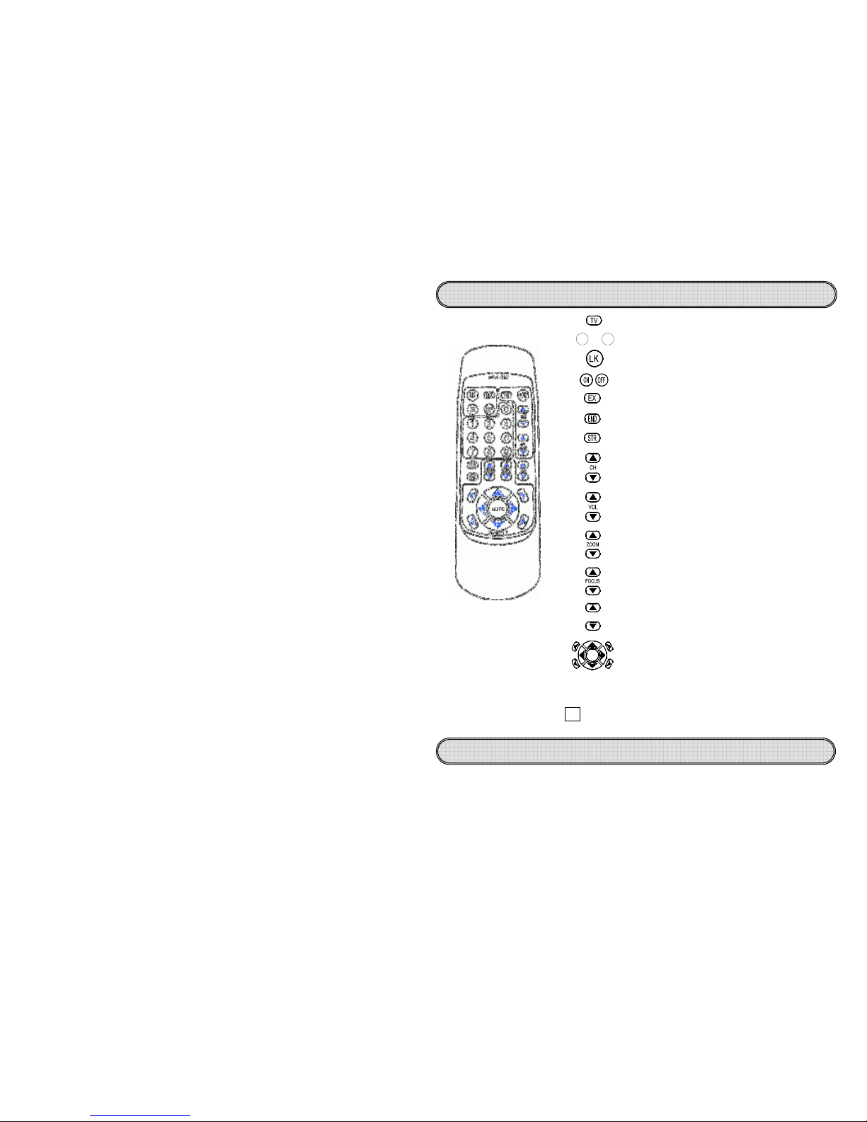
Infrared Remote Control
About the infrared remote control
Error clear
/
Unit No. display
Select Unit No.
Select Unit No. / Function setting
Alarm/subtitle display setting
Alarm/subtitle display on or off
Camera orientation control key and auto cruise key
AUTO
Manual focusing (FAR / NEAR)
Manual zoom (WIDE / TELE)
Exit function menu mode
/
Skip
Enter into function menu mode
/
OK
Move down
/
left (Function Menu Mode
)
Move up
/
right (Function Menu Mode
)
Presetting call
/
saving
/
removal
Presetting
recall
90
~
Star light night vision adjustment
SC
13
Be sure to keep the remote control within 7 meters from the receiver. All inputs shall
be made within 5 seconds, or the input mode would be cancelled automatically. In case of
erroneous input, press LK to clear before new inputs or escape from the operating mode.
1. Power on
After turning the power on or restarting the unit, it takes about 10 seconds to
restore the original status before power off.
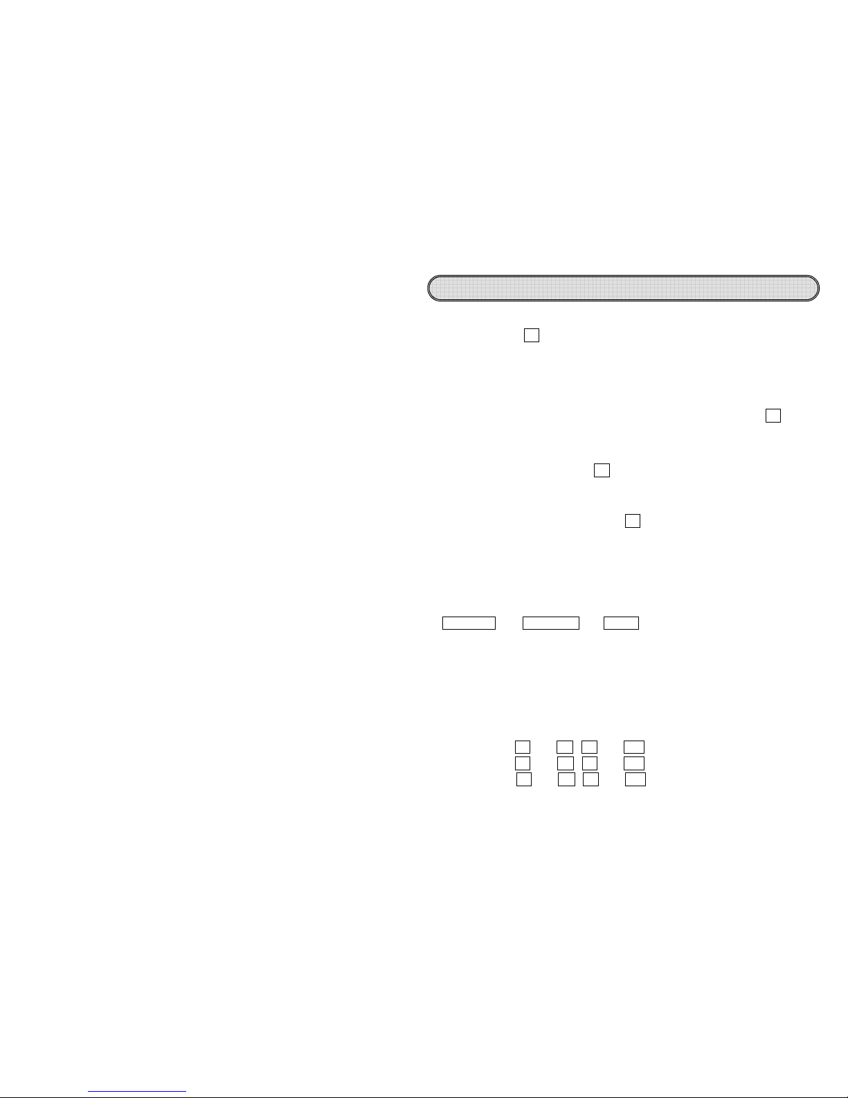
2. Selection of unit No.
Before the operation, input the unit No. To select No. 001 camera, press TV once to
enter into the unit No. selection mode and when the OSD message reading
CALL ID001-255---appears below the screen, key in a 3-digit code for the
remote control of orientation or setting of the camera.
Example: To select ID 1 camera: TV
→0→0→
1,
the operation must be completed
within 5 seconds, or the unit No. selection mode would be cancelled automatically.
When selecting a correct unit No., the unit No. will appear on the screen,
otherwise no display would appear on the screen.
If you do not know the unit No., press LK to check the unit No. and then proceed
with the input accordingly.
3. Remote control
When selecting a correct unit No., you may press the orientation key or the lens control
key. Press it down for operation and release it to stop. With the operation, a symbol or
message will appear below the screen, such as: Orientation key Up, Down, Left ,
right , Tilt left up, Tilt right up, Tilt left down, tilt right down,
ZOOM z/Z, FOCUS f/F, SCSET SENSE UPx2. You may also
adjust luminance of the star light night vision OFF / ×2 / ×4 / ×6 / ×8 / ×12 / ×16 / ×32
/ ×64 (The larger the number is, the better the image).
The orientation control will move at the pace per AUTO ZOOM (5~ 60/sec.).
For speed setting, please refer to MENUSPEED-SETmenu setting.
For manual focusing of the lens, every time you operate ZOOM, an auto focusing
will be activated once.
4. Alarm and subtitle display On/Off
Alarm input 1: EX→1→ON / EX→1→OFF
Alarm input 2: EX→2→ON / EX →2→OFF
Subtitle display: EX→3→ON / EX →3→OFF
when the alarm goes on, the corresponding preset No. 1 and 2 may carry out auto
tracking of alarm with the display locked.
For alarm mode setting, please refer to MENUAL-SET
Infrared remote control mode
14
5. Preset points call, save and remove
(OSD messages appear below the screen)
Call: END→0→0→2, CALL PRESET 2:---
Save: END→END→0→1→0, SAVE PRESET 10:---
Erase: END→END→END→0→0→3, ERASE PRESET 3:--
6. Recalling preset positions
By pressing and releasing STR, you may recall next preset positions and by pressing
and releasing repeatedly it, you may check whether all points are correctly preset. To
execute STR, the horizontal scanning or auto cruise will stop.
7. Auto scan mode
AUTO →0: Horizontal scanning for observation to the left and right.
Before execution, enter into MENUAUTOPAN-SET.
8. Group auto cruise mode
AUTO →1Preset cruise points 1~32
AUTO →2Preset cruise points 33~ 64
AUTO →3Preset cruise points 65~ 96
AUTO →4Preset cruise points 97~128
AUTO →5Preset cruise points 1~128
For cruise groups 1~5, at least 2 points shall be preset.
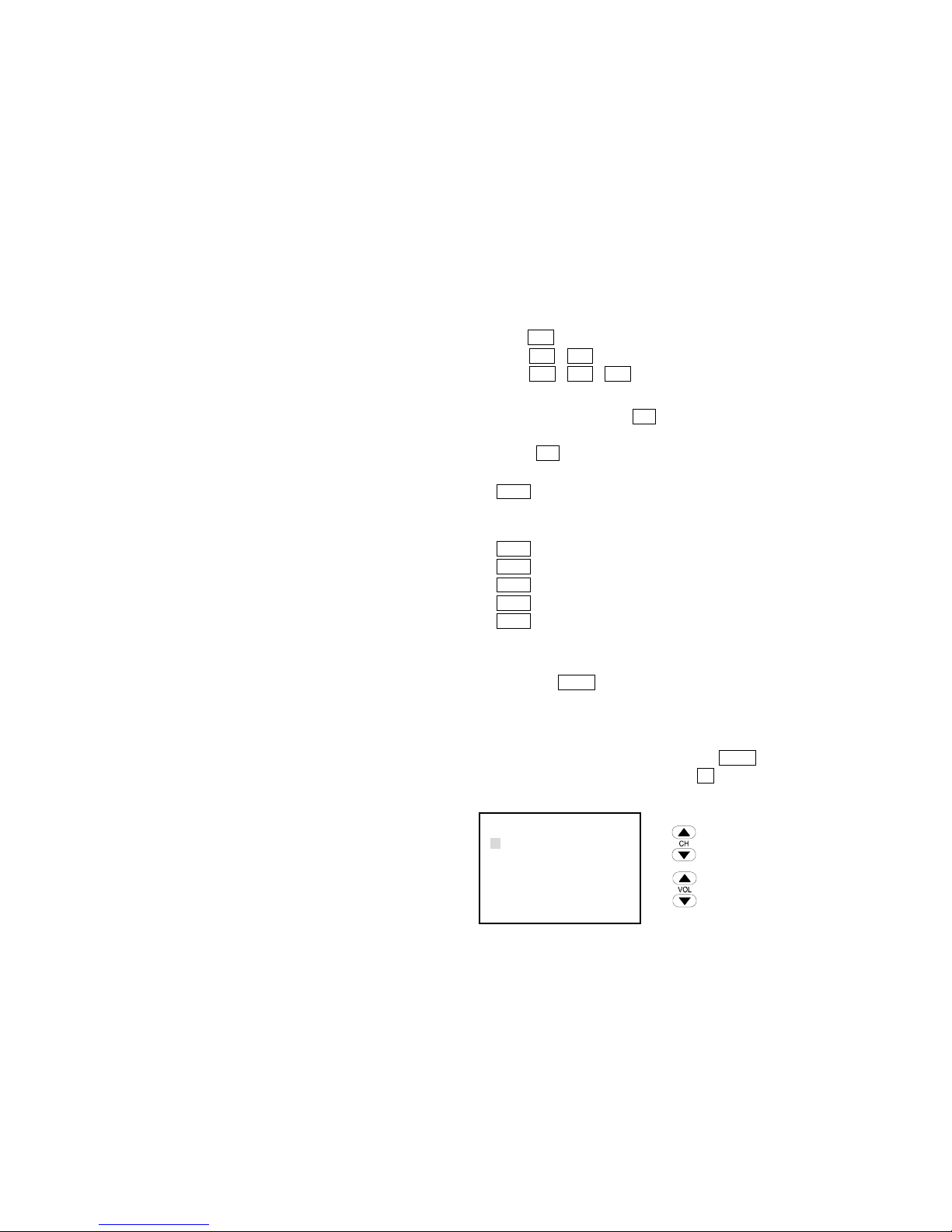
9. OSD MENU SELECTION
By holding VOL (for 5 seconds), the screen will show the OSD menu that suggests
that you are in the setting mode.
When entering into MENU, you will not be able to run the ID menu for selection,
preset and cruise, though you may keep the orientation under control. To escape
from the menu, you may press and release VOL repeatedly until001 SYSTEM
SETUPdisappears or you may press LK to escape rapidly from the function menu.
To do so, you must wait until001 SYSTEM SETUPdisappears before proceeding.
Up / Right key
Down / Left key
Enter into Function Menu / OK key
Escape from function setting / Escape key
001 SYSTEM SETUP
→GROUP-SET
AL-SET
SPEED-SET MAX
AUTOPAN-SET
PROTOCOL DYNA 9600
CAMERA-SET

15
001 SYSTEM SETUP
GROUP-SET GROUP1
→DELAY-SET 01
SPEED-SET
X2
001 SYSTEM SETUP
AL-SET
→AL1 NO
AL2 NO
OUTPUT AUTO
001 SYSTEM SETUP
GROUP-SET
→GROUP1
GROUP2
GROUP3
GROUP4
GROUP5
10. GROUP-SET
Select→
GROUP-SET
Enter into group setting and select groups 1 ~ 5.
10.1 Setting preset point stay time and speed
Enter into single group setting
DELAY-SET is to set stay time of each point for
1 ~ 64 seconds
01, 02, 04, 08, 16, 32, 64 seconds
SPEED-SET is to set movement speed of each point
per second at 5~ 60
MIN, X1, X2, X3, X4, X5, MAX
11. AL-SET
Select→AL-SET
AL1, AL2 set trigger mode in Group 1, 2:
NO
alarm triggered in case of short circuit
NC
alarm triggered when ON
OFF alarm triggered when OFF
OUTPUT is to set alarm output mode:
In case of AUTO alarm, output is closed automatically
per trigger of AL1, AL2
CTRL In case of alarm, turn off LK for output
OFF alarm output goes off

16
001 SYSTEM SETUP
GROUP-SET
AL-SET
SPEED-SET MAX
AUTOPAN-SET
PROTOCOL DYNA 9600
→CAMERA-SET
001 SYSTEM SETUP
AUTOPAN-SET
START-POINT →ENT
END-POINT
ENT
SPEED-SET X3
001 SYSTEM SETUP
GROUP-SET
AL-SET
SPEED-SET →MAX
AUTOPAN-SET
PROTOCOL DYNA 9600
CAMERA-SET
001 SYSTEM SETUP
GROUP-SET
AL-SET
SPEED-SET MAX
AUTOPAN-SET
PROTOCOL →DYNA 9600
CAMERA-SET
12. SPEED-SET
Select→SPEED-SET
Adjust orientation pace per second to 5~ 60
MIN, X1, X2, X3, X4, X5, MAX
13. AUTOPAN-SET
Select→AUTOPAN-SET
START-POINT to set monitoring angle to the left
END-POINT to set monitoring angle to the right
SPEED-SET to set horizontal rotation pace per
second at 5~ 60
MIN, X1, X2, X3, X4, X5, MAX
14. PROTOCOL
Select→PROTOCOL
(For RS-485 systems)
DYNA9600
(DYNACOLOR Rate 9600)
PELCOP9600
(PELCO-P Rate 9600)
PELCOP4800
(PELCO-P Rate 4800)
PELCOD2400
(PELCO-D Rate 2400)
LILIN9600
(LILIN Rate 9600)
The controls vary depending on the selected control codes that are compatible.
For communication protocol, please contact the dealer.
15. CAMERA-SET
Select→CAMERA-SET
Please refer to Page 22 for lens internal setting.

17
1. Basic setting
Please refer to Page 7 for the system mode and setting of unit No. and set the system
as required for the control to work with, such as the control keyboard, DVR and PC.
This device is working in standard RS-485 communication format at the bps as set.
The user may contact the dealer for the communication protocol code and write the
control program on his (her) own.
2. Connection
Please refer to Page 11 for the control and connection methods and the wire
specification. The reference connection diagram shows the simple layout and this
device is able to connect with as many as 128 units and in integrated application with
other systems.
For the connection with more than 1 camera or multi-system connection, please
contact the dealer.
3. Controls
The functions under control depend on the preset communication format code and the
level of support rendered by the designated controllers and its operation is determined
by that of the designated controller.
Daily cleaning
Use a soft and dry cloth to wipe off the dust from the spherical hood. Dirt or
scratch may jeopardize focusing.
Lens cleaning
Use an exclusive lens cleanser to remove dust from the lens.
Removal of stubborn stains
To remove stubborn stains from the surface of the camera, use a soft cloth
damped with diluted mild detergent before wiping it clean with a piece of soft
cloth.
When cleaning, be sure not to hurt the surface of the spherical hood or leave
water stains that may deteriorate image.
Do not use benzene, iluent or gasoline and other corrosive solvents
These solvents may hurt the casing or make the spherical hood change of color.
RS-485 control mode
Maintenance & cleaning

18
1. No display after successful mounting.
a. Please check whether you have removed the dust cap from the camera.
(Some models come with this cap)
b. Please check whether the video output connector of the camera is properly
connected with the input of the monitor.
c. Please check whether the peripheral wiring of the monitor and the power supply
of the camera is normal.
2. Why the preset point, setting and control fail to reach the preset point?
a. Please check whether the preset points are in normal operation.
b. Please check whether the preset points in a specific group has 2 or more preset
points.
c. Have you set all the preset points of one group in the same position?
3. Unsuccessful control
a. Please check whether the control wire has the polarities properly connected.
b. Is the unit No. properly set or have you selected the correct unit No. before
operation.
c. Is the infrared remote control aimed at the receiver’s range or have you replaced
the batteries of the remote control?
d. Are the control code and the communication rated correct? (For RS-485 control )
4. Troubled control
a. Please check whether the control wire is in poor contact or nor properly grounded
or the wire experiences interference.
b. Please check whether the extended control wire uses an independent twin-thread
wire? (For RS-485 control. )
c. Is the control distance too long or the wire is not as rated.
For technical support, please contact the dealer.
Troubleshooting

19
SMK-054 Multi-function keyboard
For RS-485 control system
Expandable to a medium or large system for
integrated controls
Extra-large LCD for easy reading
Built-in universal joy stick of easy handling
A variety of functions programmable with push
buttons
Apt for use in indoor environments
SMK-037 Wireless keyboard
For RS-485 control system
Expandable to a medium or large system for
integrated controls
Extra-large back-light LCD for easy reading
Wireless remote control of easy handling
A variety of humane wireless ratio control
features
Apt for use in indoor environments
SKC-IR485 Wireless control for camera
For RS-485 control system
Expandable into a simple one-to-multiple
camera
Compact & lightweight for easy installation
Wireless remote control of easy operation
A variety of humane wireless ratio control
features
Apt for use in indoor environments
SKC-485A 485 signal amplifier
For RS-485 control system
Signal amplification for extended control
distance
Built-in surge protection and scramble signal
resistance
Compact & lightweight for easy installation
Apt for use in indoor environments
Optional accessories

20
Optional accessories
Assembly view
SPD-300 Reinforced wall hanger
Easy installation
Rigid and aesthetically designed
Made of rigid materials
Apt for use in indoor and outdoor
environments
SKC-2348 232 Signal converter
For RS-485 control system
To convert RS-232 signals into RS-485 signals
To convert PC, DVR control signals
Compact & lightweight for easy installation
Apt for use in indoor environments
SKC-4823 485 Signal converter
For RS-485 control system
To convert RS-485 signals into RS-232 signals
Apt for all RS-232 communication systems
The system features integrated or extended
control distance
Compact & lightweight for easy installation
Apt for use in indoor and outdoor
environments

21
Page1 MAIN MENU Page2 MAIN MENU
Page3 MAIN MENU
Page4 MAIN MENU
Page5 MAIN MENU
Lens internal setting
SETUP MENU [1/5]
CAMERA ID OFF
SENSE UP OFF
AISHUT AUTO.
AES FIX.
BLC OFF
AGC +4
SETUP MENU [2/5]
W HITE BAL ATW.
SYNC OFF
ZOOM
DIGITAL ZOOM OFF
FOCUS
AUTO FOCUS OFF
SETUP MENU [3/5]
POSITION LOAD.
H-GAIN +6
V-GAIN +6
M OTION OFF
IR ON.
INITIAL ON
SETUP MENU [5/5]
ZOOM+AF OFF
AF SLEEP OFF
SCALE OFF
LANGUAGE ENGLISH
MISC
SETUP MENU [4/5]
DEFAULT CANCEL
FREEZE OFF
FREEZE MODE FIELD
ZOOM SPEED MAX
FOCUS SPEED MIN
GAMMA GAMMA1

22
1 CAMERA ID
Move cursor to CAMERA ID, press ENTER key to enter ID
FUNCTION SELECTING menu, then Press UP or DOWN
key to select ON.
Press ENTER key to enter CAMERA ID EDIT menu.
Page1 MAIN MENU
Press ENTER key to edit ID character, then press UP or
DOWN key to select ID character position (total twenty
character positions).
Press ENTER key to enter ID characters menu.
CAMERA ID EDIT MENU
Select the desired character by using UP and DOWN
button, and Press ENTER key to confirm the blinking
character .The first character is saved and the cursor in
the button of the screen moves to next (Maximum 20
characters).
ID CHARACTER MENU
Move cursor to POSITION, press ENTER key to enter ID
POSITION SELECTING menu, then Press UP or DOWN
key to select ID POSTION L-U,R-D,L-D or R-U .
CAMERA ID EDIT MENU
SETUP MENU [1/5]
CAMERA ID →ON.
SENSE UP OFF
AISHUT AUTO.
AES FIX.
BLC OFF
AGC +4
CAMERA ID
EDIT
→POSITION L-U
- - - - - - - - - - - - - - - - - - - -
CAMERA ID
EDIT
POSITION L-U
↓
- - - - - - - - - - - - - - - - - - - -
CAMERA ID
EDIT
POSITION L-U
↓
- - - - - - - - - - - - - - - - - - - -

23
2 SENSE UP
Move cursor to SENSE UP, press ENTER key to enter
SENSE UP FUNCTION SELECTING menu, then Press UP
or DOWN key to select OFF, x2, x4, x6, x8, x12, x16, x32 or
x64 (0 Frame, 2 Frames, 4 Frames, 6 Frames, 8 Frames, 12
Frames, 16 Frames, 32 Frames, 64 Frames, 9 steps
adjustable).
Page1 MAIN MENU
3 AISHUT
3.1 AISHUT AUTO MODE
Move cursor to AISHUT, press ENTER key to enter
AISHUT FUNCTION SELECTING menu, then Press UP or
DOWN key to select AUTO.
Press ENTER key to enter AUTO LEVEL ADJUSTMENT
menu.
Page1 MAIN MENU
Press ENTER key to enter AUTO LEVEL SELECTING
menu, then Press UP or DOWN key to select MIN, +1, +2,
+3, +4, +5, +6, +7, MAX.
AUTO LEVEL ADJUSTMENT MENU
SETUP MENU [1/5]
CAMERA ID OFF
SENSE UP →OFF
AISHUT AUTO.
AES FIX.
BLC OFF
AGC +4
SETUP MENU [1/5]
CAMERA ID OFF
SENSE UP OFF
AISHUT →AUTO.
AES FIX.
BLC OFF
AGC +4
AISHUT
AUTO LEVEL →+4

24
3.2 AISHUT FIX MODE
Move cursor to AISHUT, press ENTER key to enter
AISHUT FUNCTION SELECTING menu, then Press UP or
DOWN key to select FIX.
Press ENTER key to enter FIX LEVEL ADJUSTMENT
menu.
Page1 MAIN MENU
Press ENTER key to enter FIX LEVEL SELECTING menu,
then Press UP or DOWN key to select MIN, +1, +2, +3, +4,
+5, +6, +7, MAX.
FIX LEVEL ADJUSTMENT MENU
4 AES
4.1 AES FIX MODE
Move cursor to AES, press ENTER key to enter AES
FUNCTION SELECTING menu, then Press UP or DOWN
key to select FIX.
Press ENTER key to enter FIX LEVEL ADJUSTMENT
menu.
Page1 MAIN MENU
Press ENTER key to enter FIX LEVEL SELECTING menu,
then Press UP or DOWN key to select OFF, 1/100, 1/250,
1/500, 1/1000, 1/2000, 1/4000 or 1/10000.
FIX LEVEL ADJUSTMENT MENU
SETUP MENU [1/5]
CAMERA ID OFF
SENSE UP OFF
AISHUT →FIX.
AES FIX.
BLC OFF
AGC +4
AISHUT
FIX LEVEL →+4
SETUP MENU [1/5]
CAMERA ID OFF
SENSE UP OFF
AISHUT AUTO.
AES →FIX.
BLC OFF
AGC +4
AES
FIX LEVEL →OFF

25
4.2 AES AUTO MODE
Move cursor to AES, press ENTER key to enter AES
FUNCTION SELECTING menu, then Press UP or DOWN
key to select AUTO.
Press ENTER key to enter AUTO LEVEL ADJUSTMENT
menu.
Page1 MAIN MENU
Press ENTER key to enter AUTO LEVEL SELECTING
menu, then Press UP or DOWN key to select MIN, +1, +2,
+3, +4, +5, +6, +7, MAX.
AUTO LEVEL ADJUSTMENT MENU
5 BLC
Move cursor to BLC , press ENTER key to enter BLC
FUNCTION SELECTING menu, then Press UP or DOWN
key to select ON.
Press ENTER key to enter BLC ARES AND LEVEL
ADJUSTMENT menu.
Page1 MAIN MENU
Press ENTER key to enter BLC AREA ADJUSTMENT
menu.
AREA AND LEVEL ADJUSTMENT MENU
AES
AUTO LEVEL →+4
SETUP MENU [1/5]
CAMERA ID OFF
SENSE UP OFF
AISHUT AUTO.
AES →AUTO.
BLC OFF
AGC +4
SETUP MENU [1/5]
CAMERA ID OFF
SENSE UP OFF
AISHUT AUTO.
AES AUTO.
BLC →ON.
AGC +4
BLC
→BLC AREA
BLC LEVEL
MIN

26
Press ENTER key to set BLC AREA BLOCK. Press UP or DOWN key to select BLC AREA
BLOCK.
OPD WINDOW
This method is suited for cases where the main subject is fixed within the screen.
The important object in a scene is usually placed in the center of the monitor’s screen. In this
mode more photometric weight is given to the center of the screen than to the edge of the
picture, this function will eliminate the interference by strong background light whit makes the
camera picture dark. The size and location of center window can be adjust freely by user within
48 area on screen (detail please see OPD setting)
Press ENTER key to enter BLC LEVEL ADJUSTMENT
menu, then Press UP or DOWN key to select MIN, +1, +2,
+3, +4, +5, +6, MAX.
6 AGC
Move cursor to AGC, press ENTER key to enter AGC
LEVEL SELECTING menu, then Press UP or DOWN key to
select BASE, +1, +2, +3, +4, +5, +6, +7, MAX (0dB ~ 36dB,
9 steps adjustable).
AGC ADJUSTMENT MENU
BLC
BLC AREA
BLC LEVEL →MIN
SETUP MENU [1/5]
CAMERA ID OFF
SENSE UP OFF
AISHUT AUTO.
AES FIX.
BLC OFF
AGC →+4

27
7 WHITE BALANCE
7.1 ATW
Move cursor to WHITE BAL, press ENTER key to enter
WHITE BAL FUNCTION SELECTING menu, then Press UP
or DOWN key to select ATW.
Press ENTER key to enter ATW LEVEL ADJUSTMENT
menu.
Page2 MAIN MENU
Press ENTER key to enter ATW LEVEL ADJUSTMENT
menu, then Press UP or DOWN key to select RED, RED+,
RED++, RED+++, MIDDLE, BLUE, BLUE+,
BLUE++,BLUE+++, 9 steps adjustable.
ATW LEVEL ADJUSTMENT MENU
Move cursor to R-Y GAIN, press ENTER key to enter R-Y
GAIN ADJUSTMENT menu, then Press UP or DOWN key
to select MIN, +1, +2, +3, +4, +5, +6, +7, MAX, 9 steps
adjustable.
R-Y GAIN ADJUSTMENT MENU
Move cursor to B-Y GAIN, press ENTER key to enter B-Y
GAIN ADJUSTMENT menu, then Press UP or DOWN key
to select MIN, +1, +2, +3, +4, +5, +6, +7, MAX, 9 steps
adjustable.
R-Y GAIN ADJUSTMENT MENU
SETUP MENU [2/5]
W HITE BAL →ATW.
SYNC OFF
ZOOM
DIGITAL ZOOM OFF
FOCUS
AUTO FOCUS OFF
ATW LEVEL
ATW LEVEL →
MIDDLE
R-
Y GAIN +4
B-Y GAIN +4
ATW LEVEL
ATW LEVEL MIDDLE
R-Y GAIN →
+4
B-Y GAIN +4
ATW LEVEL
ATW LEVEL
MIDDLE
R-
Y GAIN +4
B-Y GAIN →+4

28
7.2 AWB
Move cursor to WHITE BAL, press ENTER key to enter
WHITE BAL FUNCTION SELECTING menu, then Press UP
or DOWN key to select AWB.
Press ENTER key to enter AWB LEVEL ADJUSTMENT
menu.
Page2 MAIN MENU
Press ENTER key to enter AWB LEVEL ADJUSTMENT
menu, then Press UP or DOWN key to select RED, RED+,
RED++, RED+++, MIDDLE, BLUE, BLUE+, BLUE++,
BLUE+++, 9 steps adjustable.
AWB LEVEL ADJUSTMENT MENU
Move cursor to R-Y GAIN, press ENTER key to enter R-Y
GAIN ADJUSTMENT menu, then Press UP or DOWN key
to select MIN, +1, +2, +3, +4, +5, +6, +7, MAX, 9 steps
adjustable.
R-Y GAIN ADJUSTMENT MENU
Move cursor to B-Y GAIN, press ENTER key to enter B-Y
GAIN ADJUSTMENT menu, then Press UP or DOWN key
to select MIN, +1, +2, +3, +4, +5, +6, +7, MAX, 9 steps
adjustable.
R-Y GAIN ADJUSTMENT MENU
SETUP MENU [2/5]
W HITE BAL →AWB.
SYNC OFF
ZOOM
DIGITAL ZOOM OFF
FOCUS
AUTO FOCUS OFF
AWB LEVEL
AWB LEVEL →
MIDDLE
R-
Y GAIN +4
B-Y GAIN +4
AWB LEVEL
AWB LEVEL MIDDLE
R-Y GAIN →
+4
B-Y GAIN +4
AWB LEVEL
AWB LEVEL MIDDLE
R-
Y GAIN +4
B-Y GAIN →+4

29
8 SYNC
This function is used to adjust phase of external sync.
When input external sync, we can press ENTER key to set
SYNC ON, then press UP or DOWN key to adjust phase.
Page2 MAIN MENU
9 ZOOM
Move cursor to ZOOM, press ENTER key to enter ZOOM
ADJUSTMENT menu.
Page2 MAIN MENU
Press UP or DOWN key to select ZOOM WIDE to TELE, 1
to 23 times adjustable.
ZOOM ADJUSTMENT MENU
10 DIGITAL ZOOM
Move cursor to DIGITAL ZOOM, press ENTER key to enter
DIGITAL ZOOM FUNCTION SELECTING menu.
Press UP or DOWN key to select DIGITAL ZOOM ON or
OFF (1 to 10 times adjustable).
Page2 MAIN MENU
SETUP MENU [2/5]
W HITE BAL AWB.
SYNC →OFF
ZOOM
DIGITAL ZOOM OFF
FOCUS
AUTO FOCUS OFF
SETUP MENU [2/5]
W HITE BAL AWB.
SYNC OFF
→ZOOM
DIGITAL ZOOM OFF
FOCUS
AUTO FOCUS OFF
ZOOM
WIDE - - - - - - - - - - -
TELE
SETUP MENU [2/5]
W HITE BAL AWB.
SYNC OFF
ZOOM
DIGITAL ZOOM →ON
FOCUS
AUTO FOCUS OFF

30
11 FOCUS
Move cursor to FOCUS, press ENTER key to enter FOCUS
ADJUSTMENT menu.
Page2 MAIN MENU
Press UP or DOWN key to select FOCUS FAR to NEAR.
FOCUS ADJUSTMENT MENU
12 AUTO FOCUS
Move cursor to AUTO FOCUS, press ENTER key to enter
AUTO FOCUS FUNCTION SELECTING menu.
Press UP or DOWN key to select AUTO FOCUS ON or
OFF.
Page2 MAIN MENU
13 POSITION
Move cursor to POSITION, press ENTER key to enter
POSITION FUNCTION SELECTING menu.
Press UP or DOWN key to select LOAD, SAVE, ALARM,
and OSD.
Page3 MAIN MENU
SETUP MENU [2/5]
W HITE BAL AWB.
SYNC OFF
ZOOM
DIGITAL ZOOM OFF
→
FOCUS
AUTO FOCUS OFF
FOCUS
FAR - - - - - - - - - - - NEAR
SETUP MENU [2/5]
W HITE BAL AWB.
SYNC OFF
ZOOM
DIGITAL ZOOM OFF
FOCUS
AUTO FOCUS →ON
SETUP MENU [3/5]
POSITION →LOAD.
H-GAIN +6
V-GAIN +6
M OTION OFF
IR ON.
INITIAL ON

31
There have 64 steps (position with zoom & focus) can be
programmed.
After adjusting position with zoom & focus, Press ENTER
key to enter POSITION SAVE SELECTNG menu.
Press UP or DOWN key to select position (1 to 64 position
that you want to save), then press ENTER key that will be
saved.
POSITION SAVE MENU
Press ENTER key to enter POSITION LOAD SELECTNG
menu.
Press UP or DOWN key to select position (1 to 64 position
that you want to LOAD), then press ENTER key that will
be loaded.
POSITION LOAD MENU
Press ENTER key to enter ALARM POSITION SELECTNG
menu.
Press UP or DOWN key to select alarm position (OFF, 1 to
64 position that you want to set), then press ENTER key
that will be set.
When input alarm signal, alarm position will be loaded.
ALARM POSITION MENU
Display position number.
OSD set ON, position number will be display on
right-up(R-U) or right-down(R-D) of the screen.
POSITION OSD MENU
POSITION SAVE
POSITION SAVE →1
POSITION LOAD
POSITION LOAD →
1
ALARM POSITION
ALARM POSITION →OFF
POSITION OSD
OSD →
OFF
POSITION R-U

32
14 H-GAIN
This is used to enhance the compensation of the picture quality.
H-GAIN: Horizontal Compensation
Move cursor to H-GAIN, press ENTER key to enter H-GAIN
ADJUSTMENT menu.
Press UP or DOWN key to select MIN, +1, +2, +3, +4, +5, +6,
+7, +8, +9, +11, MAX, 13 steps adjustable.
Page3 MAIN MENU
15 V-GAIN
This is used to enhance the compensation of the picture quality.
V-GAIN: Vertical Compensation
Move cursor to V-GAIN, press ENTER key to enter V-GAIN
ADJUSTMENT menu.
Press UP or DOWN key to select MIN, +1, +2, +3, +4, +5, +6,
+7, +8, +9, +11, MAX, 13 steps adjustable.
Page3 MAIN MENU
16 MOTION
MOTION DETECTION FUNCTION
Move cursor to MOTION, press ENTER key to enter
MOTION ON/OFF menu.
Press UP or DOWN key to select ON.
Page3 MAIN MENU
SETUP MENU [3/5]
POSITION LOAD.
H-GAIN →+6
V-GAIN +6
M OTION OFF
IR ON.
INITIAL ON
SETUP MENU [3/5]
POSITION LOAD.
H-GAIN +6
V-GAIN →+6
M OTION OFF
IR ON.
INITIAL ON
SETUP MENU [3/5]
POSITION LOAD.
H-GAIN +6
V-GAIN +6
M OTION →ON.
IR ON.
INITIAL ON

33
Press ENTER key to enter MOTION FUNCTION menu.
Press UP or DOWN key to select motion detection AREA,
LEVEL (Sensitivity), TIME, OSD.
When detecting motion, it will output alarm signal.
MOTION MENU
17 IR
IR FILTER REMOVABLE FUNTION (DAY & NIGHT FUNCTION)
Move cursor to IR, press ENTER key to enter IR ON/OFF
menu.
Press UP or DOWN key to select ON.
Page3 MAIN MENU
Press ENTER key to enter IR SW FUNCTION menu.
Press UP or DOWN key to select IR SW detection INT.
IR SW can detect INT. (AGC and SENSE UP) signal.
IR SW INT. MENU
Press ENTER key to enter IR INT LEVEL ADJUSTMENT
menu.
Press UP or DOWN key to select IR INT LEVEL MIN, +1, +2,
+3, +4, +5, +6, +7, +8, +9, +11, +12, +13, +14, +15, +16, MAX,
18 steps adjustable.
IR INT LEVEL MENU
MOTION
→
AREA
LEVEL +4
TIME 30sec
OSD OFF
IR SW
IR SW →INT.
SETUP MENU [3/5]
POSITION LOAD.
H-GAIN +6
V-GAIN +6
M OTION ON.
IR →ON.
INITIAL ON
IR INT LEVEL
IR INT LEVEL →MAX

34
*1 *2
*3 OFF x 2 x 4 x 6 x 8 x 12 x 16 x 32 x 64
BASE x x MAX 16 15 14 13 11 9
+1 x MAX 15 14 13 12 11 9 7
+2 x 16 14 13 12 11 10 8 6
+3 x 15 13 12 11 10 9 7 5
+4 MAX 14 12 11 10 9 8 6 4
+5 16 13 11 10 9 8 7 5 3
+6 15 12 10 9 8 7 6 4 2
+7 14 11 9 8 7 6 5 3 1
MAX 13 10 8 7 6 5 4 2 MIN
IR INT LEVEL TABLE
NOTE1:
*1
: AGC LEVEL
*2: IR INT LEVEL (ACT UP THE LEVEL)
*3: SENSE UP
NOTE2:
IR INT LEVEL (MAX) Approach 15Lux (illumination)
IR INT LEVEL (MIN) Approach 0.02Lux (illumination)
Press ENTER key to enter IR SW FUNCTION menu.
Press UP or DOWN key to select IR SW detection EXT.
IR SW will be set manual mode.
IR SW EXT. MENU
Press UP or DOWN key to select IR EXT LEVEL MAX or
MIN.
IR EXT LEVEL MAX : IR CUT OFF (B/W MODE)
IR EXT LEVEL MIN : IR CUT ON (COLOR MODE)
IR EXT LEVEL MENU
IR SW
IR SW →EXT.
IR EXT LEVEL
IR INT LEVEL →MAX

35
18 INITIAL
FOCUS RESET FUNCTION
Move cursor to INITIAL, press ENTER key to enter
INITIAL ON/OFF menu.
Press UP or DOWN key to select ON/OFF.
Page3 MAIN MENU
19 DEFAULT
RESTART THE CAMERA AND RESET PARAMETERS TO FACTORY’S DEFAULT.
Move cursor to DEFAULT, press ENTER key to enter
DEFAULT CANCEL/OK menu.
Press UP or DOWN key to select OK, then press ENTER
key.
Page4 MAIN MENU
20 FREEZE
FREEZE PICTURE FUNCTION
Move cursor to FREEZE, press ENTER key to enter
FREEZE ON/OFF menu.
Press UP or DOWN key to select ON/OFF.
Page4 MAIN MENU
SETUP MENU [3/5]
POSITION LOAD.
H-GAIN +6
V-GAIN +6
M OTION ON.
IR ON.
INITIAL →ON
SETUP MENU [4/5]
DEFAULT →CANCEL
FREEZE OFF
FREEZE MODE FIELD
ZOOM SPEED MAX
FOCUS SPEED MIN
GAMMA GAMMA1
SETUP MENU [4/5]
DEFAULT CANCEL
FREEZE →OFF
FREEZE MODE FIELD
ZOOM SPEED MAX
FOCUS SPEED MIN
GAMMA GAMMA1

36
21 FREEZE MODE
FREEZE FIELD (or FRAME) OF PICTURE FUNCTION
Move cursor to FREEZE MODE, press ENTER key to
select FREEZE MODE menu.
Press UP or DOWN key to select FIELD/FRAME.
Page4 MAIN MENU
22 ZOOM SPEED
ZOOM SPEED ADJUSTMENT
Move cursor to ZOOM SPEED, press ENTER key to enter
ZOOM SPEED SELECTING menu, then Press UP or DOWN
key to select MAX, +3, +2, +1, MIN (5 steps adjustable).
Page4 MAIN MENU
23 FOCUS SPEED
FOCUS SPEED ADJUSTMENT
Move cursor to set FOCUS SPEED, press ENTER key to
FOCUS SPEED SELECTING menu, then Press UP or
DOWN key to select MIN, +1, +2, +3, MAX (5 steps
adjustable).
Page4 MAIN MENU
SETUP MENU [4/5]
DEFAULT CANCEL
FREEZE OFF
FREEZE MODE →FIELD
ZOOM SPEED MAX
FOCUS SPEED MIN
GAMMA GAMMA1
SETUP MENU [4/5]
DEFAULT CANCEL
FREEZE OFF
FREEZE MODE FIELD
ZOOM SPEED →MAX
FOCUS SPEED MIN
GAMMA GAMMA1
SETUP MENU [4/5]
DEFAULT CANCEL
FREEZE OFF
FREEZE MODE FIELD
ZOOM SPEED MAX
FOCUS SPEED →MIN
GAMMA GAMMA1

37
24 GAMMA
GAMMA SELECT
Move cursor to set GAMMA menu, press ENTER key to
select GAMMA mode , then Press UP or DOWN key to
select GAMMA1 or GAMMA2.
GAMMA1 = 0.45
GAMMA2 = 1.0
Page4 MAIN MENU
25 ZOOM + AF
ZOOM TRIGGER AUTO FOCUS
Move cursor to set ZOOM+AF mode, press ENTER key
into select ZOOM+AF menu.
Press UP or DOWN key to select ON/OFF.
Page5 MAIN MENU
26 AF SLEEP
AUTO FOCUS SLEEP (WORK IN AUTO FOCUS ON MODE)
Move cursor to AF SLEEP, press ENTER key to enter
AF SLEEP ON/OFF menu.
Press UP or DOWN key to select ON/OFF.
The image change less than auto focus range in five
minutes; the auto focus will sleep in AF SLEEP ON mode.
If the image change more ±6dB than auto focus range,
the auto focus will wake up.
Page5 MAIN MENU
SETUP MENU [4/5]
DEFAULT CANCEL
FREEZE OFF
FREEZE MODE FIELD
ZOOM SPEED MAX
FOCUS SPEED MIN
GAMMA →GAMMA1
SETUP MENU [5/5]
→ZOOM+AF OFF
AF SLEEP OFF
SCALE OFF
LANGUAGE ENGLISH
MISC
SETUP MENU [5/5]
ZOOM+AF OFF
→AF SLEEP OFF
SCALE OFF
LANGUAGE ENGLISH
MISC

38
27 SCALE
ZOOM SCALE DISPLAY
Move cursor to SCALE, press ENTER key to enter
SCALE ON/OFF menu.
Press UP or DOWN key to select ON/OFF.
The zoom scale will be display on right-down of the
screen in SCALE ON mode.
Note: The zoom scale is non-linear approximate
value. It’s a reference value for user.
Page5 MAIN MENU
28 LANGUAGE
OSD LANGUAGE SELECT
Move cursor to LANGUAGE, press ENTER key to enter
LANGUAGE selecting menu.
Press UP or DOWN key to select ENGLISH, DEUTSCH or
ITALIANO language.
Page5 MAIN MENU
29 MISC
Move cursor to MISC, press ENTER key to enter MISC
menu.
Page5 MAIN MENU
SETUP MENU [5/5]
ZOOM+AF OFF
AF SLEEP OFF
SCALE OFF
LANGUAGE ENGLISH
→MISC
SETUP MENU [5/5]
ZOOM+AF OFF
AF SLEEP OFF
→SCALE OFF
LANGUAGE ENGLISH
MISC
SETUP MENU [5/5]
ZOOM+AF OFF
AF SLEEP OFF
SCALE OFF
→LANGUAGE ENGLISH
MISC

39
29.1 H-REVERS
Horizontal Reverse (Mirror) Function
Move cursor to H-REVERS, press ENTER key to enter
FREEZE ON/OFF menu.
Press UP or DOWN key to select ON/OFF.
MISC MENU
29.2 V-REVERS
Vertical Reverse (Up-side Down) Function
Move cursor to V-REVERS, press ENTER key to enter
FREEZE ON/OFF menu.
Press UP or DOWN key to select ON/OFF.
MISC MENU
29.3 POSI / NEGA
Positive or Negative Picture Function
Move cursor to POSI/NEGA, press ENTER key to enter
POSI/NEGA menu.
Press UP or DOWN key to select POSI/NEGA.
MISC MENU
MISC
H-REVERS →
OFF
V-REVERS OFF
POSI/NEGA POSI
PRIORITY AGC
M ASK A OFF
M ASK B OFF
MISC
H-
REVERS OFF
V-REVERS →OFF
POSI/NEGA POSI
PRIORITY AGC
M ASK A
OFF
M ASK B OFF
MISC
H-
REVERS OFF
V-REVERS OFF
POSI/NEGA →POSI
PRIORITY AGC
M ASK A O
FF
M ASK B OFF

40
29.4 PRIORITY
Selecting IR SW INT Detecting Signal
Move cursor to PRIORITY, press ENTER key to enter
PRIORITY menu.
Press UP or DOWN key to select AGC/SENSE UP.
MISC MENU
29.5 MASK A / B
MASKING AREA SETTING
Move cursor to MASK A/B, press ENTER key to enter
MASK A/B menu.
Press UP or DOWN key to select ON/OFF.
Then press ENTER key to enter MASK A/B SETTING
menu.
MISC MENU
Move cursor to H-POSITION, V-POSITION, H-SIZE or
V-SIZE press ENTER key to enter NUMBER SETTING
menu.
Press UP or DOWN key to adjust number (Adjusting
H-POSITION, V-POSITION, H-SIZE or V-SIZE).
CONNECTED set OFF, MASK will be fixed.
CONNECTED set ON, MASK will be connected with zoom.
MASK A / B SETING MENU
MISC
H-
REVERS OFF
V-REVERS OFF
POSI/NEGA POSI
PRIORITY →
AGC
M ASK A OFF
M ASK B OFF
MISC
H-
REVERS OFF
V-REVERS OFF
POSI/NEGA POSI
PRIORITY AGC
M ASK A →
ON.
M ASK B OFF
MASK A / B
H-POSITION →
032
V-POSITION 064
H-
SIZE 048
V-SIZE 032
CONNECTED OFF

41
FOR ANY QUESTIONS OR COMMENTS:
customerservice
@
robustocctv.com
Dealer: _______________________________________________
Date of purchase: ______________________________________
Model:________________________________________________
Date of manufacture: ___________________________________
 Loading...