

Page 1

Installation manual
for System Controller for K18 absorption heat pump
Expansion kit
Page 2

Revision: A
Code: D-LBR809
This Installation manual has been drawn up and printed by Robur S.p.A.; whole or partial reproduction of this Installation manual is prohibited.
The original is led at Robur S.p.A.
Any use of this Installation manual other than for personal consultation must be previously authorised by Robur S.p.A.
The rights of those who have legitimately led the registered trademarks contained within this publication are not aected.
With the aim of continuously improving the quality of its products, Robur S.p.A. reserves the right to modify the data and contents of this
Installation manual without prior notice.
Page 3

Installation manual – Expansion kit
3
INDEX OF CONTENTS
I Introduction ................................................
p.4
Recipients .........................................................................
p.4
II Symbols and denitions ............................
p.4
II.1 Key to symbols ................................................................
p.4
II.2 Terms and denitions ...................................................
p.4
III Warnings .....................................................
p.4
III.1 General and safety warnings .....................................
p.4
III.2 Conformity .......................................................................
p.5
III.3 Equipment ........................................................................
p.5
III.4 Exclusions of liability and warranty .........................
p.5
1 General information and system diagrams
............................................................................
p.6
2 Assembly and installation .......................
p.10
2.1 Installing the expansion kit into the CSK18
enclosure .........................................................................
p.10
3 Electrical hookup ......................................
p.14
3.1 Hooking up the room unit ........................................
p.14
3.2 Temperature sensor connection ............................
p.15
3.3 Water circulation pump connection .....................
p.15
3.4 Mixer valve connection ..............................................
p.16
3.5 External request signal connection to CSK18
enclosure .........................................................................
p.17
4 Commissioning .........................................
p.17
4.1 Using the QAA75.611 advanced room unit's
interface ..........................................................................
p.17
4.2 Commissioning procedure .......................................
p.17
4.3 Functional tests ............................................................
p.17
4.4 Setting the system to STAND-BY ............................
p.18
5 Settings .....................................................
p.19
5.1 Optimising heating service ......................................
p.19
5.2 Optimising DHW service ...........................................
p.20
5.3 Optimizing auxiliary boiler management ...........
p.20
6 Errors .........................................................
p.20
6.1 List of errors and troubleshooting instructions
............................................................................................
p.20
6.2 Error log ...........................................................................
p.22
7 Special operations and congurations
..........................................................................
p.22
Appendix A: technical data ......................
p.23
RVS21.826, QAA75.611, QAA55.110 ......................
p.23
AVS55.196 .......................................................................
p.23
Page 4
Introduction
4
I
I INTRODUCTION
Installation manual
This Installation manual contains all the information required for
installing and conguring the Expansion kit for all K18 Simplygas heat pump units (Gas Absorption Heat Pump) and K18 Hybrigas hybrid units (Gas Absorption Heat Pump and integrated
auxiliary boiler module), in line with one of the standard system
congurations also described in the document. The manual is
a supplement to the System Controller Installation Manual; as
such, it must be used in combination with the latter.
Referring to this manual requires familiarity with Robur
products and assumes that certain information included
in the product manuals to which this document refers.
RECIPIENTS
This Manual is intended:
▶
for electrical installers for proper installation of the control
equipment;
▶
for installers and authorised Technical Assistance Centres
Robur (TAC) for conguration;
II SYMBOLS AND DEFINITIONS
II.1 KEY TO SYMBOLS
DANGER
WARNING
NOTE
PROCEDURE
REFERENCE (to other document)
II.2 TERMS AND DEFINITIONS
KECSK18 = expansion kit.
Siemens RVS21.826 = control unit (electronic board).
CSK18 = System controller for K18 installed in the provided
enclosure.
Siemens QAA75.611 = advanced room unit.
Siemens QAA55.110 = base room unit.
Appliance / Unit K18 = equivalent terms, both used to refer to
K18 Simplygas or K18 Hybrigas unit type.
Auxiliary boiler = equipment (e.g. boiler) for the production of
heat for space heating and/or DHW, able to integrate or replace
the heat pump of the K18 unit. It is always found in the K18 Hybrigas type of unit and consists of an integrated boiler module,
whereas it is optional in K18 Simplygas units, not necessarily
supplied by Robur, and connected to the plumbing system outside the unit.
TAC = Technical Assistance Centre authorised by Robur.
DHW = domestic hot water.
III WARNINGS
This manual is an integral and essential part of the product and
must be delivered to the user together with the appliance.
III.1 GENERAL AND SAFETY WARNINGS
Installer's qualications
Installation must exclusively be performed by a Qualied
Firm and by Skilled Personnel, with specic knowledge
of electrical systems, in compliance with the laws in force
in the Country of installation.
Declaration of Conformity
Upon completing installation, the installing rm shall
issue to the owner/client the appliance's Workmanlike
Conformity Declaration, according to national/local regulations in force and the manufacturer's instructions/
provisions.
Misuse
The appliance must only be used for the purposes for
which it has been designed. Any other use is deemed
hazardous. Incorrect use may aect operation, duration
and safety of the appliance. Adhere to the manufacturer's instructions.
Electrocution hazard
Disconnect the electrical power supply before any in-
tervention/work on appliance components.
For electrical connections exclusively use compliant
components and according to the specications provided by the manufacturer.
Ensure the appliance cannot be accidentally switched
back on.
Earthing
Electrical safety depends on eective earthing system,
correctly connected to the appliance and installed according to the regulations in force.
In the event of failure
Operations on internal components and repairs may
Page 5
Warnings
Installation manual – Expansion kit
5
III
exclusively be carried out by a TAC, only using original
parts.
In the event of fault of the appliance, do not attempt
to repair and/or restore and immediately contact the
TAC .
Keep the Manual
This "Installation, Use and Maintenance Manual" must always accompany the appliance and must be handed to
the new owner or installer in the event of sale or removal.
The equipment must be installed indoors and out of the
weather. For positioning, refer to the protection rating
given in par. 2 of the K18 system controller Installation
manual.
III.2 CONFORMITY
For the appliance's technical and conformity data, refer to Appendix A
p.23
and Appendix A of the K18 system controller
Installation manual.
III.3 EQUIPMENT
The Expansion kit KECSK18 (ODSP030) unit's equipment
includes:
▶
n. 1 Siemens AVS55.196 expansion board
▶
n. 1 Siemens AVS92.280 mounting plate
▶
n. 1 Siemens AVS82.496 ribbon cable
▶
n. 1 10 pole connector (green) marked X110
▶
n. 1 7 pole connector (red ) marked X150
▶
n. 1 10 pole connector (grey) marked X152
There may also be n. 1 3 pole connector (green) marked X10,
which is not used.
The above parts may also be supplied assembled or partly assembled together.
III.4 EXCLUSIONS OF LIABILITY AND
WARRANTY
Any contractual or extra-contractual liability of the manufacturer for any damage caused by incorrect installation and/or improper use and/or failure to comply with
regulations and with the manufacturer's directions/instructions shall be disclaimed.
In particular, the warranty on the appliance may be rendered void by the following conditions:
Incorrect installation/cabling.
Misuse.
Failure to comply with the manufacturer's indications
on installation, use and maintenance.
Alteration or modication of the product or any part
thereof.
Extreme operational conditions or however outside
of the operational ranges set forth by the manufacturer.
Abnormal actions transmitted by the plant or instal-
lation to the appliance (electric shock, overheating,
power surges, etc.)
Accidental damages or due to force majeure.
Page 6

General information and system diagrams
6
1
1 GENERAL INFORMATION AND SYSTEM DIAGRAMS
The Expansion kit (KECSK18) of the System Controller for the
models of the K18 family allows the system congurations supported by it to be extended. In particular, the addition of the
kit allows the types of plumbing diagrams indicated in Figures
1.1
p.6
and1.2
p.7
to be set up with regards to the K18
Simplygas unit and those indicated in Figures 1.3
p.8
and
1.4
p.9
to be set up with regards to the K18 Hybrigas unit.
The following diagrams intend to show the hydraulic
congurations supported by System controller, including the parts to be connected to it. Ancillary hydraulic components (expansion tanks, safety valves, etc.)
are only shown as a guide; for the detailed plumbing
layout, refer to the handbook of the K18 range and to
the specic installation manual of the K18 unit used.
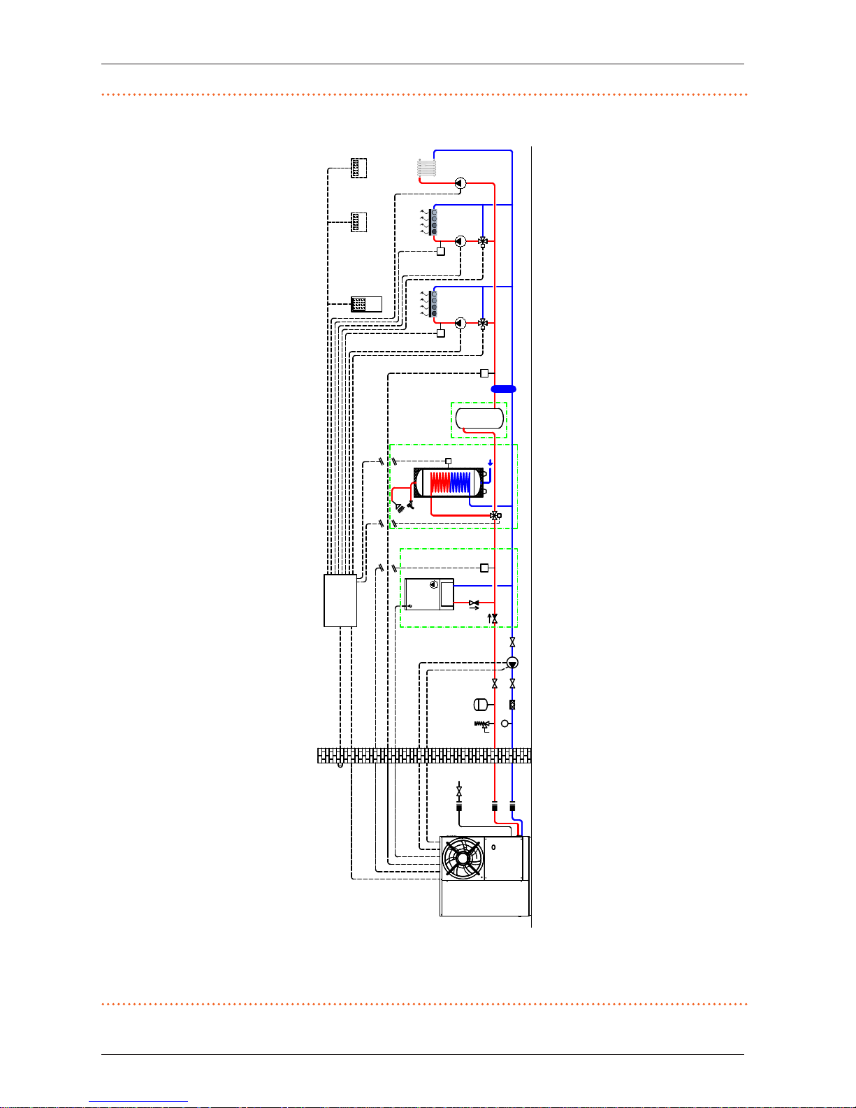
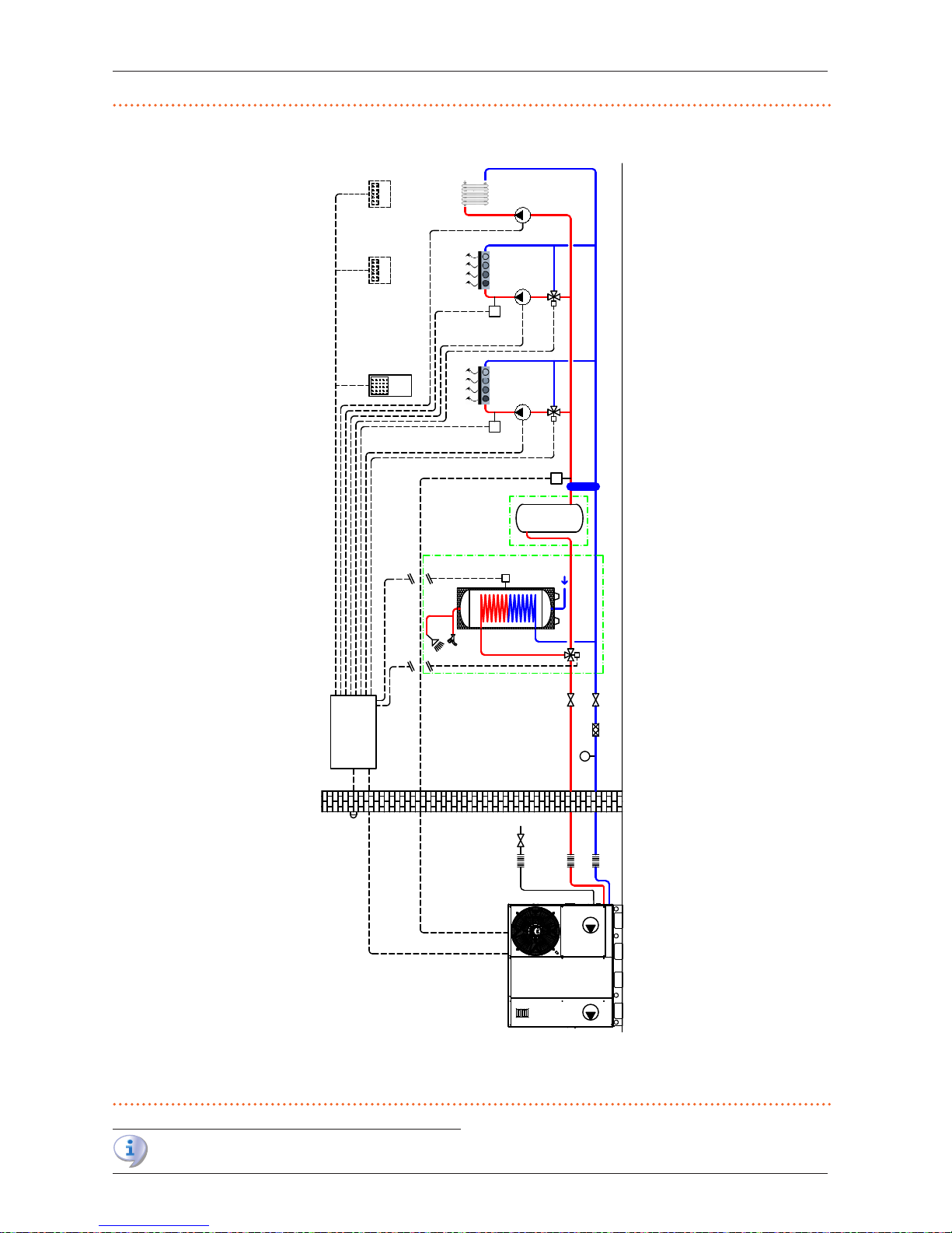
Figure1.1 System with K18 Simplygas unit, primary water circuit only and three zones, auxiliary boiler and DHW production optionals
A Unit K18 Simplygas
B Auxiliary boiler (optional)
C check valve (to be installed only in the presence of an auxiliary boiler)
D External water pump (only for C0 versions)
E By-pass section with overpressure valve
F Room unit 1 (QAA75.611)
G Thermostats (with timer) for zones
P
ST
B9
B3
Q3
B
C
ST ST
GHP'
CSK18
HC1
E
G
F
Q2
HC3
G
Q20
GHP
HC2
G
Q6
A
D
K18 CONTROL CABLE
AUX BOILER
230V W. PUMP
0-10V W. PUMP
Page 7
General information and system diagrams
Installation manual – Expansion kit
7
1
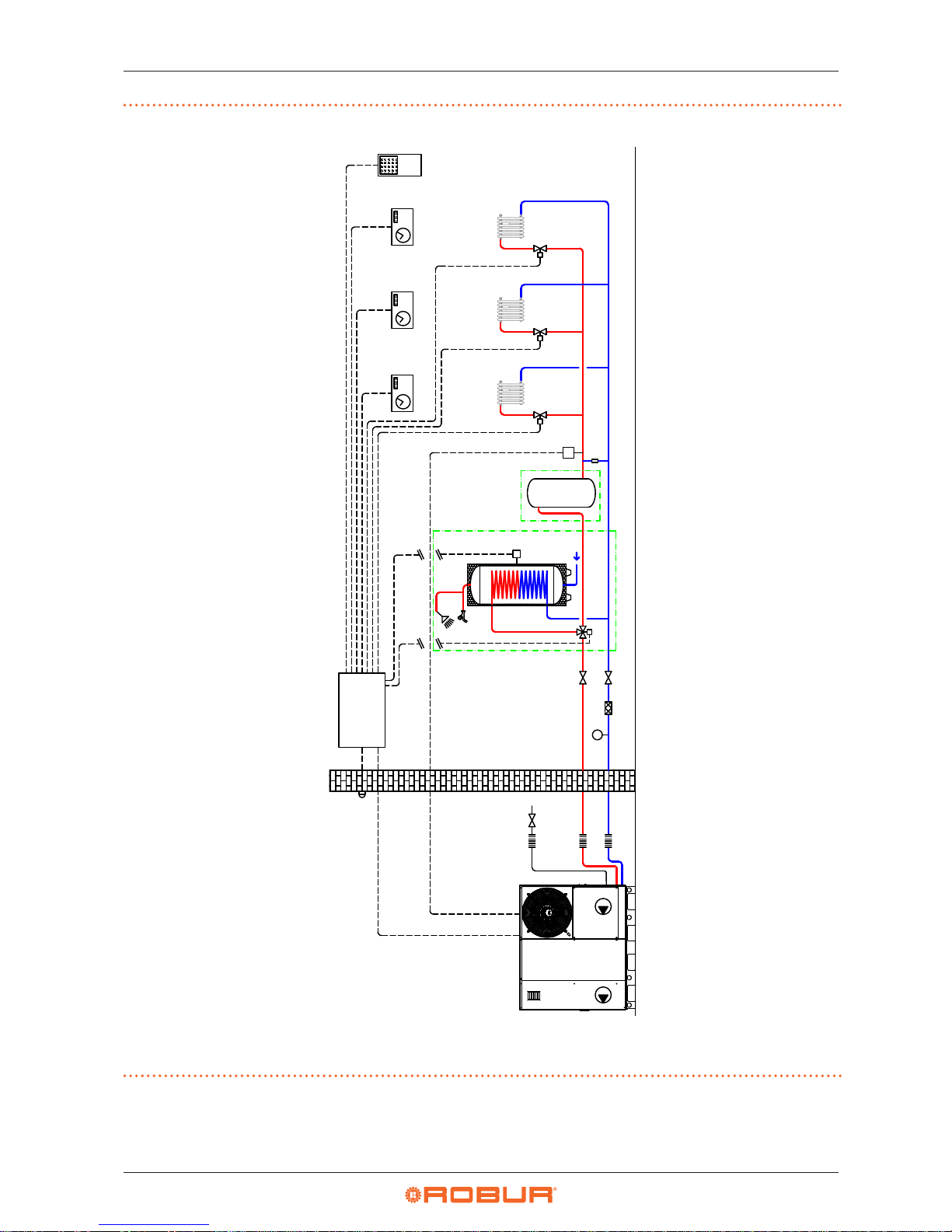
Figure1.2 System with K18 Simplygas unit, primary and secondary water circuits, up to three heating circuits, two of which are optionally mixed,
auxiliary boiler and DHW production optionals
A Unit K18 Simplygas
B Auxiliary boiler (optional)
C check valve (to be installed only in the presence of an auxiliary boiler)
D External water pump (only for C0 versions)
E Decoupling of primary/secondary circuits
F Room unit 1 (QAA75.611)
H Room unit 2 and 3 for HC2 and HC3 circuits (optionals, QAA75.611 or
QAA55.110)
P
ST
B9
B3
Q3
B
C
ST ST
GHP'
CSK18
GHP
H
E
ST
F
HC1
Q2
Y1/Y2
B1
H
HC3
Q20
ST
HC2
Q6
Y5/Y6
B12
A
D
K18 CONTROL CABLE
AUX BOILER
230V W. PUMP
0-10V W. PUMP
Page 8
General information and system diagrams
8
1
Figure1.3 System with K18 Hybrigas unit, primary water circuit only and three zones, DHW production optional
A K18 Hybrigas unit
E By-pass section with overpressure valve
F Room unit 1 (QAA75.611)
G Thermostats (with timer) for zones
P
A
ST
B9
B3
Q3
ST
CSK18
GHP
E
K18 CONTROL CABLE
HC1
G
F
Q2
HC3
G
Q20
HC2
G
Q6
Page 9
General information and system diagrams
Installation manual – Expansion kit
9
1
Figure1.4 System with K18 Hybrigas unit, primary and secondary water circuits, up to three heating circuits, two of which are optionally mixed,
DHW production optional
A K18 Hybrigas unit
E Decoupling of primary/secondary circuits
F Room unit 1 (QAA75.611)
H Room unit 2 and 3 for HC2 and HC3 circuits (optionals, QAA75.611 or
QAA55.110)
P
A
ST
B9
B3
Q3
ST
CSK18
GHP
E
K18 CONTROL CABLE
H
ST
F
HC1
Q2
Y1/Y2
B1
H
HC3
Q20
ST
HC2
Q6
Y5/Y6
B12
For water circuits with a primary circuit only (g. 1.1
p.6
and 1.3
p.8
) water circulation must be
Page 10
Assembly and installation
10
2
guaranteed to handle the K18 unit's anti-icing cycle. This
requires that a outlet/inlet bypass be installed, with overpressure valve set to open only when all zone valves are
closed.
All temperature probes (GHP, GHP’, B1, B3, B12) must be
placed and xed in dedicated thermowells, with a length
suitable to result immersed in water ow or in water
mass, using thermal paste to ensure a good heat transfer.
In case one of the optional DHW preparation tanks is
used (code OSRB012 or OSRB004), it is recommended to
use the thermowell just above mid height for the probe
B3.
Even in case other water tanks are used, place probe
B3 in an intermediate position, possibly just above mid
height.
Following installation of the KECSK18 expansion kit,
the K18 system controller is automatically congured
to facilitate the installation and commissioning of the
types of circuit indicated in g. 1.1
p.6
, 1.2
p.7
,
1.3
p.8
and 1.4
p.9
. However, it can also support
other congurations. For applications other than those
indicated in this manual, Robur provides custom consultancy service.
2 ASSEMBLY AND INSTALLATION
The Expansion kit for the K18 system controller is supplied complete with everything required for quick installation inside the
CSK18 enclosure.
Before installing the unit, check that the equipment is
not connected to its power supply.
The cabling must satisfy the requirements of safety class
II, i.e. the mains power cables and the SELV cables
must be ducted separately.
Also, keep a distance of at least 50 mm between the
ducts that contain mains cables and those which contain safety extra low voltage cables and between the
two categories of cables inside the enclosure; achieve
this by following the instructions provided in the Installation Manual of the System Controller with regards to
the choice of the input holes in the enclosure to use for
the mains connections and for the safety extra low voltage (SELV) ones.
The CSK18 and any other equipment and accessories
must be powered up only when the installation is complete. Failure to observe this instruction incurs a risk of
electrocution and short-circuit.
The CSK18 must not be exposed to water.
The unit's ambient operating temperature range is 0 °C
- 50 °C.
2.1 INSTALLING THE EXPANSION KIT INTO
THE CSK18 ENCLOSURE
Assembly and installation
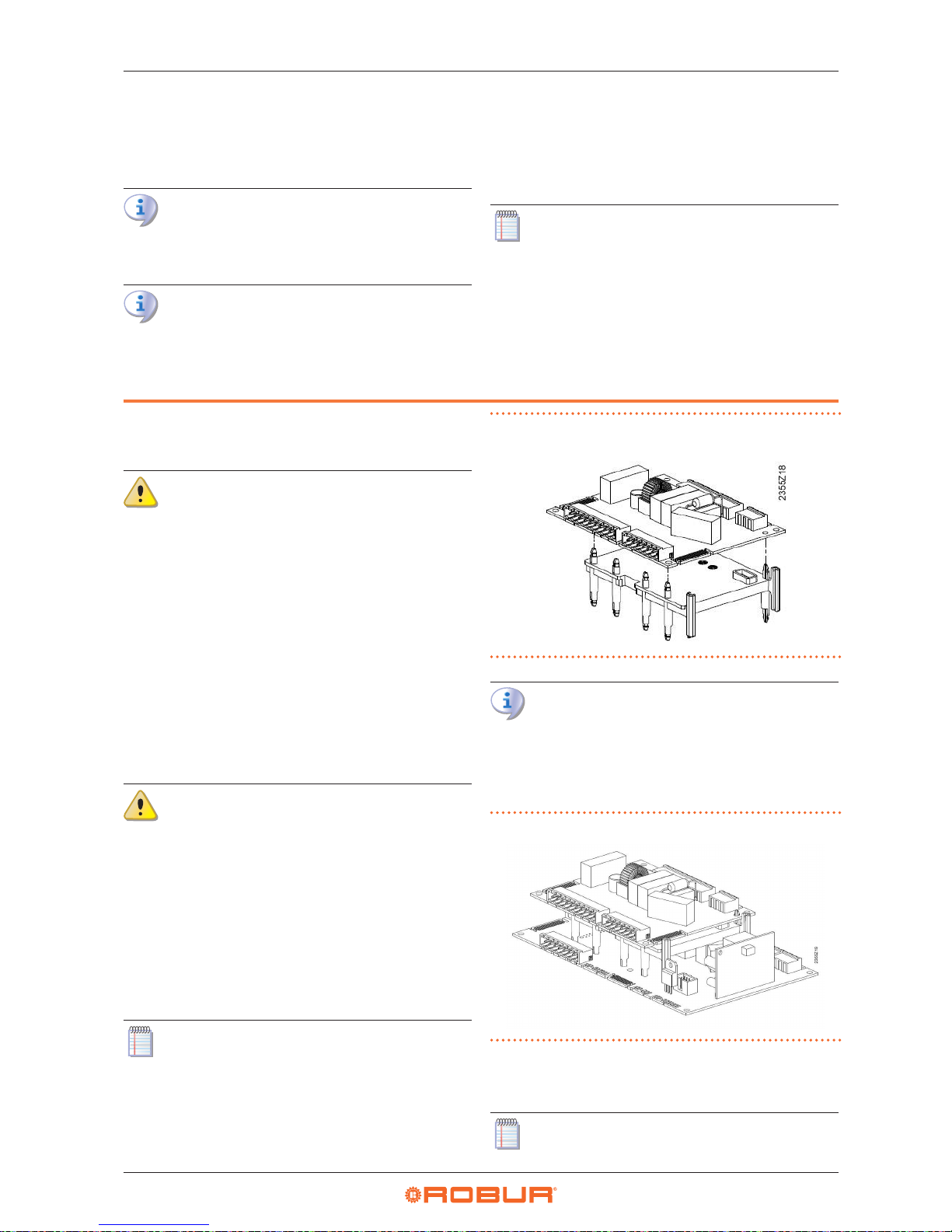
1. As shown in g. 2.1
p.10
, assemble the AVS55.196 electronic board with the plastic mounting plate; push the six
short retainers fully into the holes in the board until the
pawls click.
The Expansion kit may also be supplied with the electronic board and mounting plate assembled together; in
this case, go directly to the next step.
Figure2.1 Assembling the AVS55.196 electronic board with the
mounting plate
DO NOT remove the RVS21.826 board from the CSK18
enclosure.
2. Align the six long retainers on the bottom side of the mount-
ing plate with the holes in the RVS 21.826 electronic board
already present in the CSK18 enclosure, then push them in
until they snap into place.
Figure2.2 Detail of the two boards assembled together
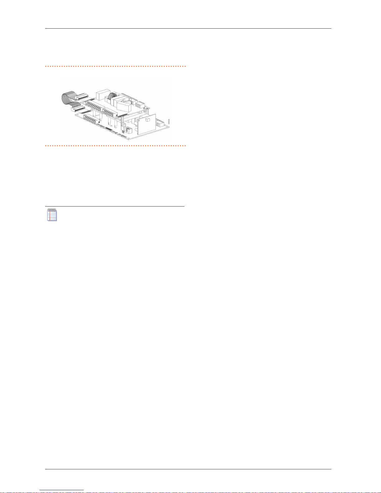
3. Push the connectors of the included AVS82.496 ribbon cable
fully in the comb connectors marked X100, on the edge of
the two electronic boards.
The Expansion kit may also be supplied with the ribbon
cable already assembled to connector X100 of the
Page 11
Assembly and installation
Installation manual – Expansion kit
11
2
AVS55.196 electronic board; in this case, insert the free
connector into the RVS21.826 board.
Figure2.3 Detail of ribbon cable connection between the two boards
4. If the expansion kit is supplied with the connectors not yet
installed, t the following into the corresponding sockets after having identied them:
▶
10 pole connector, green, X110
▶
7 pole connector, red, X150
▶
10 pole connector, grey, X152
▶
even if it is included in the kit, DO NOT install the 3 pole
green connector X10
If the expansion kit is supplied with the connectors
already installed, pull out the 3 pole green connector
X10.
5. Identify the 3 pole green connector X10 left free inside the
CSK18 enclosure and t it into the corresponding socket on
the AVS55.196 board of the Expansion kit.
Page 12
Assembly and installation
12
2
Electrical hookup
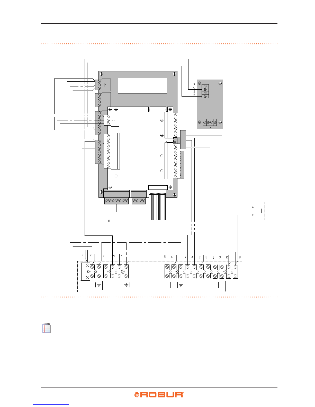
Figure2.4 Layout of components and wiring diagram of system controller for K18 with expansion kit installed
RESET
L
N
X10 1
QX1
Siemens RVS21.826
M
BX4
M
BX3
GX1
H3
M
H1
G+
M
BSB
FX3
EX4
EX3
EX2
EX1
X11 1
N
Q
N
N
N
L
L
CTRL
N
N
LINE IN
DHW Q3
AL
AL
0
+10
COM
RES
DHW
K18
EXTERN.
RESET
REQ
K18 CONTROL CABLE
GX1
AL
COM
DHW
N
Q3
L
EX1
IF30
Siemens AVS55.196
X10 1
L
N
QX3
BX31
M
1 X152
M
BX33
BX32
M
M
H33
BX34
M
G+
H31
1 X150
H32
GX1
M
M
BSB
QX33
N
X110 1
N
N
ZX34
QX32
QX31
N
QX35
QX35
Q
Q
Z
X100
FUSE6.3
D1
D3
UX3
M
DI6
DI7
M
D1
Figure 2.4
p.12
gives a schematic illustration (not to scale) of
the layout of components inside the CSK18 enclosure with the
Expansion kit installed.
The additional electrical connections, regarding the
functions handled by the Expansion kit, are made on the
included extractable connectors which t directly into
the kit's AVS55.196 electronic board, as described in this
manual.
On the other hand, unless otherwise expressly specied,
for the functions available without the Expansion kit, refer to the system controller Installation manual.
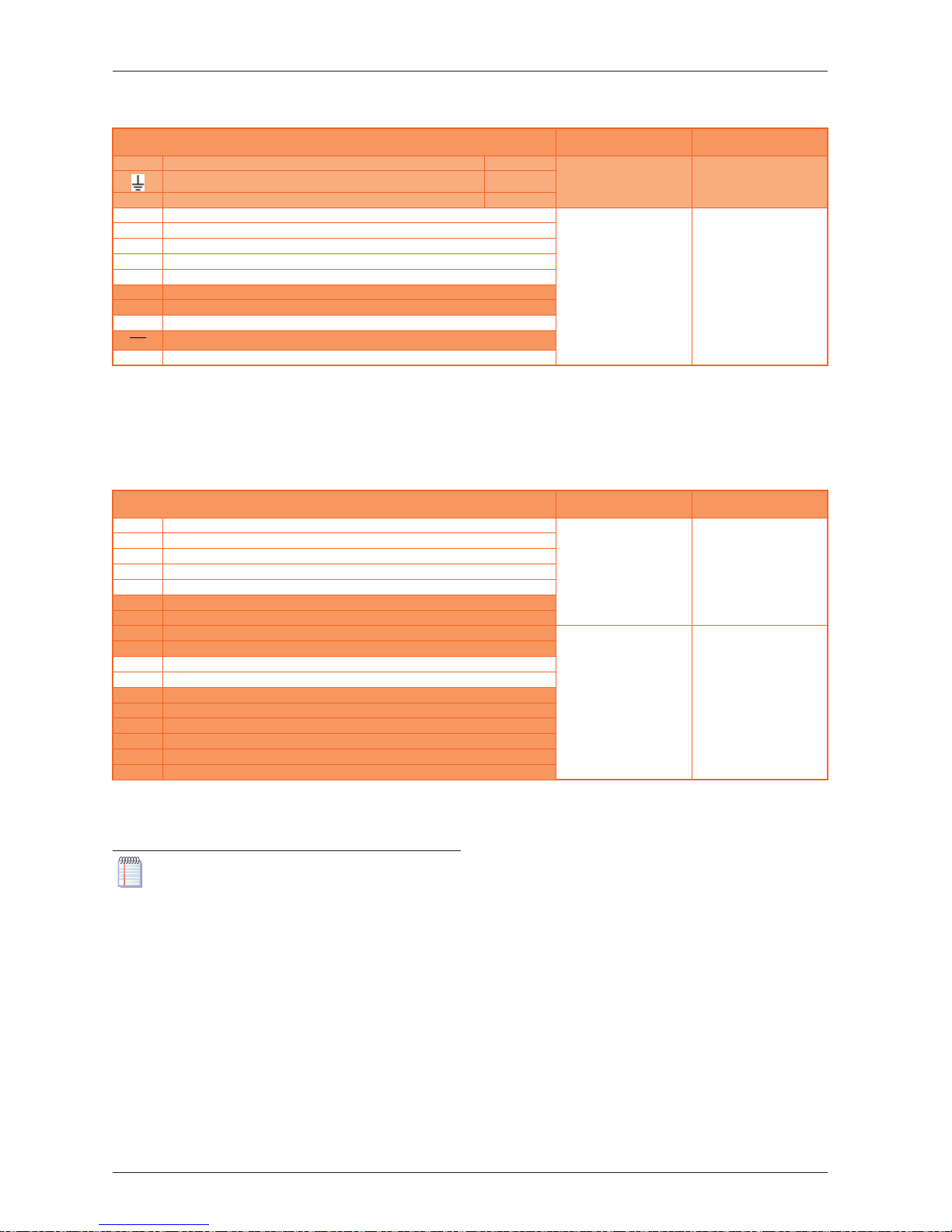
Table 2.1
p.13
lists the Line Voltage supply and signal con-
nections on the extractable connectors on the left edge of the
Siemens AVS55.196 expansion board.
To identify the position of the connectors, refer to the wiring diagram given in g. 2.4
p.12
.
To identify the plumbing system components and sensors corresponding to the Siemens function codes (e.g. Q6, Y5, Y6) refer
to the plumbing system diagrams in g. 1.1
p.6
, 1.2
p.7
,
1.3
p.8
and 1.4
p.9
.
Page 13
Assembly and installation
Installation manual – Expansion kit
13
2
Table2.1 Line Voltage connections to Siemens RVS55.196 board connectors
Function (Siemens logo on water circuit diagrams and description)
Logo on connector
Color
Connector code
Siemens
L 230 VAC phase input to RVS55.196 Pre-wired
X10
Green
BPZ:AGP5S.03A/109
Ground connection to RVS55.196 Pre-wired
N Neutral input to RVS55.196 Pre-wired
QX31 Y5 - heating circuit 2 mixer valve open phase output
X110
Green
BPZ:AGP5S.10P/109
QX32 Y6 - heating circuit 2 mixer valve close phase output
N Heating circuit 2 mixer valve neutral output
QX33 Q6 - Heating circuit 2 water pump phase output / Zone 2 valve (1)
N Q6 - Heating circuit 2 water pump neutral output / Zone 2 valve (1)
ZX34 Not used
N Not used
QX35 Q20 - Heating circuit 3 water pump phase output / Zone 3 valve
QX35
Not used
N Q20 - Heating circuit 3 water pump neutral output / Zone 3 valve
(1) Note that this function is also available when the expansion kit is not used. In this case, as indicated in the system controller Installation Manual, pump Q6 is hooked
up to terminals QX3 and N on connector X12 of the RVS21.826 electronic board.
If using the expansion kit, on the other hand, follow the diagrams and instructions given in this manual.
Table 2.2
p. 13
lists the SELV supply and signals connections
on the extractable connectors on the right edge of the Siemens
RVS55.196 expansion board.
Table2.2 SELV signal connections to Siemens AVS55.196 board connectors
Function (Siemens logo on water circuit diagrams and description)
Logo on connector
Color
Connector code
Siemens
BSB BSB+ - QAA75/QAA55 Room Unit data bus connection (1)
X150
Red
BPZ:AGP5S.07L/109
M BSB- - QAA75/QAA55 optional Room Unit data bus ground (1)
G+ G+ - QAA75 optional Room Unit backlighting power output (1)
H31 H31 - Heating circuit 3 normally open request signal input (2)
M H31 - Heating circuit 3 request signal input return
H32 Not used
GX1 Not used
H33 Not used
X152
Grey
BPZ:AGP5S.10R/109
M Not used
BX31 B12 - Heating circuit 2 temperature sensor input (mixed only)
M B12 - Heating circuit 2 temperature sensor input (mixed only)
BX32 Not used
M Not used
BX33 Not used
M Not used
BX34 Not used
M Not used
(1) These terminals need not be used to connect additional room units. They can also be connected directly in parallel to the terminals of connector X86 of the
RVS21.826 controller, or connected in cascade, as indicated in the system controller Installation manual and par. 3.1
p.14
of this manual.
(2) Input H31 is open to keep heating circuit 3 inactive. If this heating circuit is present, t a jumper between terminals H31 or insert an external request signal between
them (voltage free contact).
The temperature sensors connected to the Siemens
AVS55.196 expansion board are of the NTC 10k (Beta
3977) type.
Page 14
Electrical hookup
14
3
3 ELECTRICAL HOOKUP
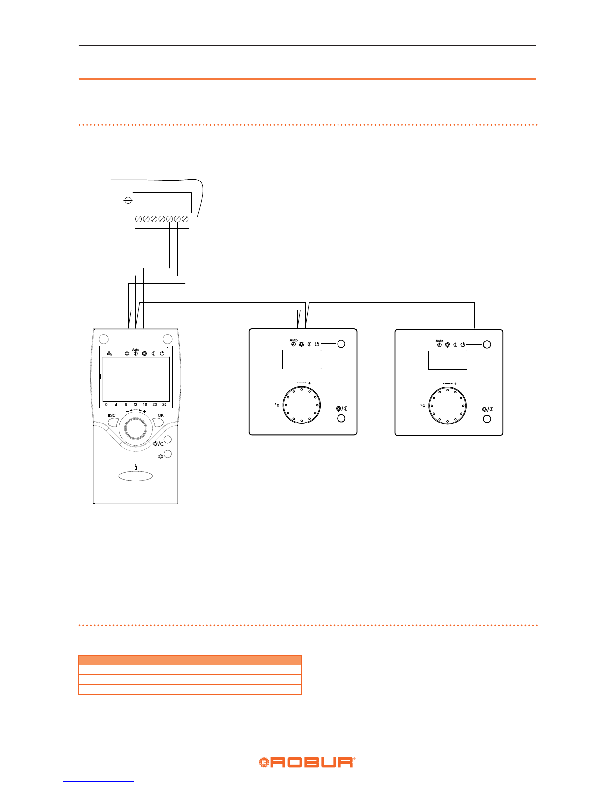
3.1 HOOKING UP THE ROOM UNIT
Figure3.1 Example of connection of three room units, one type QAA75.611, the others (optional) type QAA55.110
A Grey connector X86 (bottom edge of RVS21.826 board)
B Room unit 1 (QAA75.611)
C - D Ambient units 2 and 3 (QAA55.110) (optional code ODSP004)
NOTE Use shielded signal cable 3x0.75 mm
2
(2x0.75 mm2 for QAA55.110).
Maximum total length 400 m.
Maximum length between controller and room unit 200 m.
Both room units can also be connected to connector X86.
GX1
H3MH1
1 X86
G+
M
BSB
1 2
3
1 2 1 2
B
A
C
D
Table3.1 QAA75.611 and QAA55.110 (optional) room unit connection
RVS21.826 QAA75.611 QAA55.110
BSB 1 1
M 2 2
G+ 3 -
Page 15
Electrical hookup
Installation manual – Expansion kit
15
3
3.2 TEMPERATURE SENSOR CONNECTION
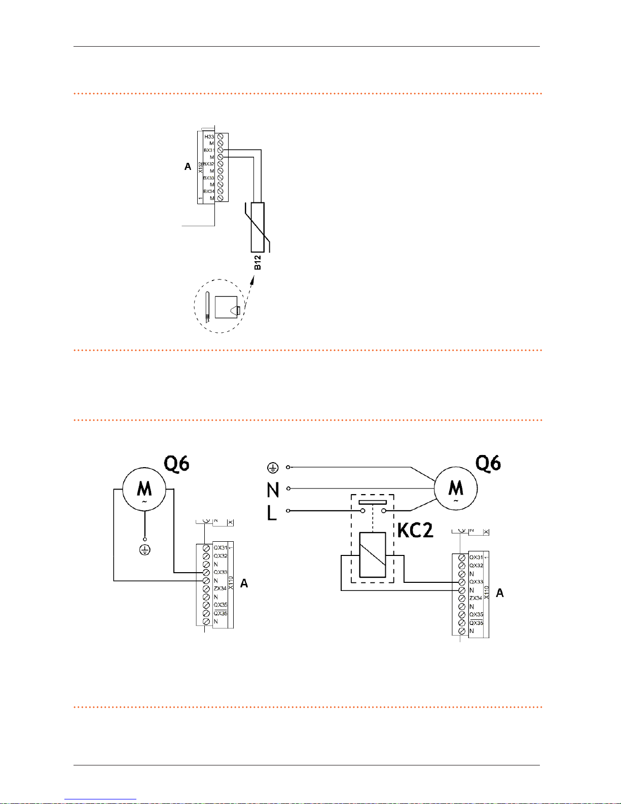
Figure3.2 Temperature sensor connection diagram (NTC 10k - Beta 3977) to AVS55.196
A Grey connector X152 (right edge of AVS55.196
board)
B12 NTC 10k Beta 3977 temperature sensor
Use of temperature sensors
B12 Only if heating circuit 2 is mixed
Use shielded cable
2 x 0.5 mm² up to 40 m
2 x 0.75 mm² up to 60 m
2 x 1.0 mm² up to 80 m
2 x 1.5 mm² up to 120 m
3.3 WATER CIRCULATION PUMP CONNECTION
3.3.1 Heating circuit 2 pump connection diagram (if present)
Figure3.3 Direct or external relay connection of heating circuit 2 pump to AVS55.196
A Green connector X110 (left edge of AVS55.196 board)
Q6 Heating circuit 2 pump
KC2 Relay
NOTE With the expansion kit installed, always use this diagram (see NOTE (1) to Table 2.1
p.13
)
Page 16
Electrical hookup
16
3
3.3.2 Heating circuit 3 pump connection diagram (if present)
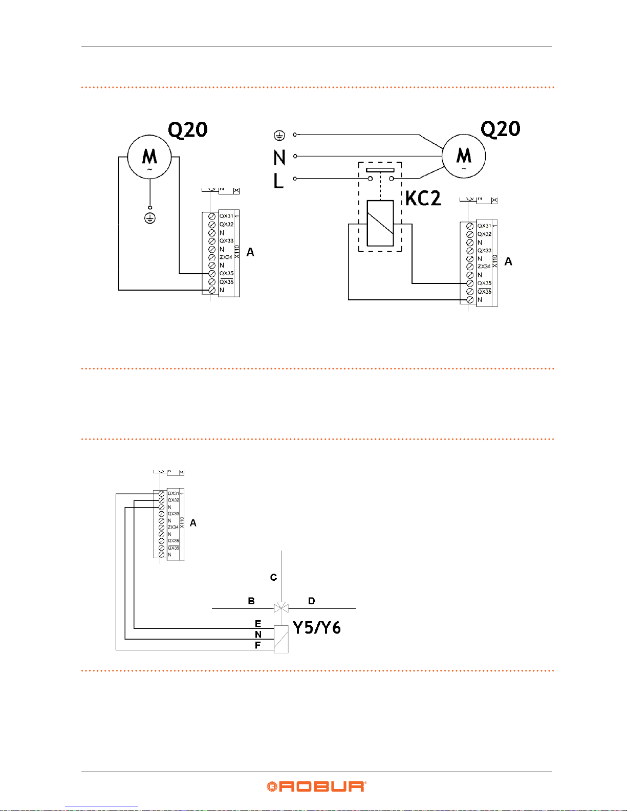
Figure3.4 Direct or external relay connection of heating circuit 3 pump to AVS55.196
A Green connector X110 (left edge of AVS55.196 board)
Q20 Heating circuit 3 pump
KC2 Relay
3.4 MIXER VALVE CONNECTION
3.4.1 Y5/Y6 mixer valve connection diagram (if present)
Figure3.5 Y5/Y6 mixer valve connection (for mixed heating circuit 2) to AVS55.196
A Green connector X110 (left edge of AVS55.196
board)
B Flow from system
C Heating circuit 2 outlet
D Heating circuit 2 inlet
E Y6: close ow from system
F Y5: open ow from system
N Neutral
Y5/Y6 Mixer valve
Page 17
Commissioning
Installation manual – Expansion kit
17
4
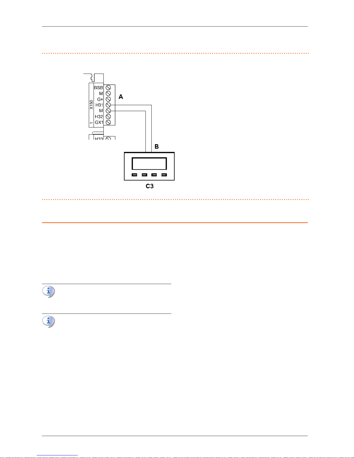
3.5 EXTERNAL REQUEST SIGNAL CONNECTION TO CSK18 ENCLOSURE
Figure3.6 Connection of optional external request signals (thermostats, thermostat timers, timers) to AVS55.196
A Red connector X150 (right edge of AVS55.196
board)
B NO voltage free contact
C3 Thermostat (with timer) for zone 3 (or circuit 3)
4 COMMISSIONING
This section gives supplementary information regarding
system commissioning, which are required when using the
Expansion kit. As previously, this section must be consulted in
combination with the matching section of the system controller
Installation manual.
It is assumed that the plumbing system and electrical installations have been completed and checked in compliance with sections 1
p.6
, 2
p. 10
and 3
p. 14
of this manual and the
matching sections of the system controller Installation manual.
The K18 and auxiliary boiler (if present) may start during
and at the end of commissioning. Make sure that the
plumbing system is complete and lled with water.
Commissioning must be done by a TAC.
4.1 USING THE QAA75.611 ADVANCED
ROOM UNIT'S INTERFACE
See the Paragraph 4.1 of the system controller Installation
manual.
4.2 COMMISSIONING PROCEDURE
Proceed as indicated in to Paragraph 4.2 of the system controller
Installation manual; when the system is powered up, also check
that the green led on the AVS55.196 expansion board lights up;
if the led does not light up, check that you have connected the 3
pole connector, green, X10 to the socket on the expansion board
and that the ribbon cable has been inserted into the comb connectors marked X100 on the RVS21.826 and AVS55.196 boards.
4.3 FUNCTIONAL TESTS
These tests are not strictly necessary, however they allow you to
quickly identify most problems with the electrical hookup and
system anomalies; we strongly recommend running them.
4.3.1 Testing the inputs and outputs
1. Access the Commissioning menu level, select the Input/out-
put test menu and select parameter 7700 (Relay test).
2. Set it to QX5 (QX5 relay output, function Q2 -> Heating cir-
cuit 1 pump) and check that the heating circuit 1 pump runs
(or the zone 1 valve opens).
3. If heating circuit 1 is of the mixed type:
Set the parameter to QX1 (QX1 relay output, function
Y1 -> open mixer valve on system outlet line) and
check that the mixer valve responds as desired.
Set the parameter to QX2 (QX2 relay output, function
Y2 -> open mixer valve on heating circuit 1 inlet line)
and check that the mixer valve responds as desired.
4. If heating circuit 2 (or zone 2) is present:
Set the parameter to QX33 (QX33 relay output on
AVS55.196 board, function Q6 -> heating circuit 2
pump) and check that the pump of heating circuit 2
runs (or the zone 2 valve opens).
5. If heating circuit 2 is present and of the mixed type:
Set the parameter to QX31 (QX31 relay output on
AVS55.196 board, function Y5 -> open mixer valve on
system outlet line) and check that the mixer valve responds as desired.
Set the parameter to QX32 (QX32 relay output on
AVS55.196 board, function Y6 -> open mixer valve on
heating circuit 2 inlet) and check that the mixer valve
responds as desired.
6. If heating circuit 3 (or zone 3) is present:
Set the parameter to QX35 (QX35 relay output on
Page 18

Commissioning
18
4
AVS55.196 board, function Q20 -> heating circuit 3
pump) and check that the pump of heating circuit 3
runs (or the zone 3 valve opens).
7. If the Domestic Hot Water function managed by the K18 unit
is present (EVO models):
Set the parameter to QX4 (QX4 relay output, function
Q3 -> set DHW diverter valve to DHW service) and
check that the diverter valve responds as desired.
8. Now select parameter 7700 again and set it to No test.
9. Select parameter 7804 (Sensor temp BX1) and check its val-
ue (sensor BX1, function B9 -> external temperature).
10. If the Domestic Hot Water function managed by the K18 unit
is present (EVO models):
Select parameter 7806 (Sensor temp BX3) and
check its value (sensor BX3, function B3 -> DHW tank
temperature).
11. If heating circuit 1 is of the mixed type:
Select parameter 7807 (Sensor temp BX4) and check
its value (sensor BX4, function B1 -> Heating circuit 1
outlet temperature).
12. If heating circuit 2 is present and of the mixed type:
Select parameter 7973 (Sensor temp BX31) and
check its value (sensor BX31, function B12 -> Heating
circuit 2 outlet temperature).
To facilitate checking the connection of each temperature sensor to its input, you can take them out of their
mounts one at a time and heat them up slightly; observe
the variation of the readings on the display to check that
they are hooked up to the right inputs.
Make sure you have restored each sensor to its own
mounting afterwards!
13. If an external request signal is connected for heating circuit
1 (or zone 1), for example, with a thermostat or thermostat
timer:
Select parameter 7844 (Input signal H1) and actuate
the external signal's contact to check that it switches
as expected from open (indicated by - - -) to closed
(indicated by o o o) and back.
NOTE: If no external request signal is present, this test
must indicate closed (o o o), due to the jumper
installed at the factory.
14. If heating circuit 2 (or zone 2) is present, and an external re-
quest is hooked up:
Select parameter 7858 (Input signal H3) and actuate
the external signal's contact to check that it switches as
expected from open (indicated by - - -) to closed (indicated by o o o) and back.
NOTE: If no external request signal is present, this test
must indicate closed (o o o), due to the jumper
added during installation.
15. If heating circuit 3 (or zone 3) is present, and an external re-
quest is hooked up:
Select parameter 7989 (Input signal H31) and actuate
the external signal's contact to check that it switches as
expected from open (indicated by - - -) to closed (indicated by o o o) and back.
NOTE: If no external request signal is present, this test
must indicate closed (o o o), due to the jumper
added during installation.
16. Now select parameter 7700 (Relay test) and set it to
Everything o.
17. Select parameter 7724 (Output test UX3) and set it to 50%
18. Access the terminal block of the K18 unit (refer to the "K18
unit connection to the CSK18 enclosure terminal block" Figure in Section 3 of the Installation manual of the System
Controller):
Check that the DC voltage between the COM and
DHW terminals is around 17 V.
Check that DC voltage between the 0 and +10 ter-
minals of the K18 CONTROL CABLE terminals group
is 5 V.
Check that the DC voltage between the COM and
RES terminals is around 8.5 V.
19. Select parameter 7700 and set it to QX4.
20. Install a temporary jumper between the EXTERN RESET ter-
minals on the CSK18 enclosure terminal block.
21. Access the terminal block of the K18 unit (refer to the "K18
unit connection to the CSK18 enclosure terminal block" Fig-
ure in Section 3 of the Installation manual of the System
Controller):
Check the voltage between the COM and DHW termi-
nals again: it should now be around 0 V.
Check the voltage between the COM and RES termi-
nals again: it should now be around 0 V.
22. Set parameter 7700 to No test.
23. Select parameter 7724 (Output test UX3) and set it to - - -
(test deactivated).
24. Press ESC twice to inlet to the start screen.
25. Remove the temporary jumper between the EXTERN RESET
terminals on the CSK18 enclosure terminal block.
4.3.2 Checking the start and stop commands on the
heat pump
Refer to par. 4.3.2 of the system controller Installation manual.
4.3.3 Checking the start and stop commands on the
auxiliary boiler (if present)
Refer to par. 4.3.2 of the system controller Installation manual.
4.4 SETTING THE SYSTEM TO STANDBY
Refer to par. 4.4 of the system controller Installation manual.
Page 19
Settings
Installation manual – Expansion kit
19
5
5 SETTINGS
This section gives supplementary information regarding the optimisation of the system settings, which are required when using
the Expansion kit. As previously, this section must be consulted
in combination with the matching section of the system controller Installation manual.
5.1 OPTIMISING HEATING SERVICE
5.1.1 Heating circuits (or zones) 1 and 2
Refer to Paragraphs 5.1.1 and 5.1.2 respectively of the System
Controller Installation manual.
5.1.2 Heating circuit 3 (or zone 3) (if present)
This circuit (or zone) is precongured to be inactive; if present, it
must be activated by adding a jumper or external request signal
(e.g. zone thermostat or thermostat timer), as described in gure
3.6
p.17
.
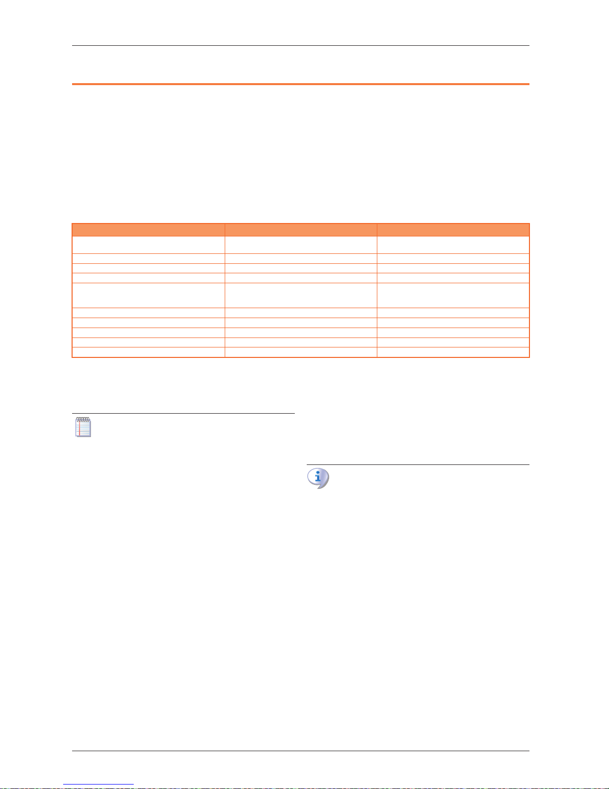
Once activated, the precongured settings are those given in
Table 5.1
p.19
.
Table5.1 Heating circuit 3 (or zone 3) preconguration (if present)
Preconguration Dependency on parameter
Operating mode
Automatic
(Comfort 6 – 22 Monday – Sunday)
1300
Comfort setpoint 21 °C 1310
Reduced setpoint 18 °C 1312
Protection setpoint 7 °C 1314
Heating curve slope
1.26
(water setpoint around 56 °C with external
temperature -10 °C)
1320
Summer/winter heating limit 18 °C 1330
Flow temp setpoint min 8 °C 1340
Flow temp setpoint max 65 °C 1341
Room inuence 20% 1350
Room temperature limitation 2.5 °C 1360
To change the settings of Table 5.1
p.19
, access the Engineer
menu level, and then the Heating circuit 3 menu; then select
the parameters indicated in Table 5.1
p.19
and modify them
as desired.
For information about the choice of operating mode and
time programming, refer to par. 5.1.3
p. 19
. For information on the heating curve settings and the min/max
water temperature setpoint, see par. 5.1.4
p. 19
. For
information on the room inuence and room temperature limitation settings, see par. 5.1.5
p.19
.
5.1.3 Selecting the operating mode and time
programming
Refer to par. 5.1.3 of the system controller Installation manual
for the description of the operating modes and for the time programming of heating circuits 1 and 2.
For the time programming of heating circuit 3 (obligatory if
the circuit is running in Automatic mode), proceed as indicated for heating circuit 1 in the above mentioned paragraph of
the system controller Installation manual, but using the Time
prog heating/cooling 3 menu; in this case, use parameters 540
(Preselection), 541 - 546 (period settings) and 555 (Copy).
5.1.4 Setting the heating curve slope and min/max
outlet water setpoints
Refer to Paragraph 5.1.4 of the system controller Installation
manual.
5.1.5 Setting the Room inuence and Room
temperature limitation parameters
Refer to Paragraph 5.1.5 of the system controller Installation
manual for a general description of the Room inuence and
Room temperature limitation functions, as well as for the settings relating to heating circuits 1 and 2.
Room inuence function for heating circuit 3 (if present)
Heating circuit 3, if present, is precongured to use this function in relation to the included room unit 1 temperature reading,
with a mild compensating action (20%), which is suited to many
installations. To modify the degree of inuence, or disable the
function entirely:
▶
Select parameter 1350 as described in par. 5.1.2
p. 19
of
this manual, and set the inuence percentage (%), or - - - to
disable the function entirely.
Setting a value of 100 % disables the heating curve. It is
best not to use this setting, or even very high inuence
percentages. For most applications, do not exceed a setting of 30 %.
Room temperature limitation function for heating circuit 3 (if
present)
Heating circuit 3 is precongured to use this function in relation
to the temperature read by room unit 1 (included), with a value
of 2.5 K (the service request is interrupted when room unit 1
reads a temperature 2.5 degrees higher than the setpoint). To
change this setting or disable the function:
▶
Select parameter 1360 as described in par. 5.1.2
p. 19
of
this manual, and set the desired value, or - - - to disable the
function entirely.
5.1.6 Setting the building time constant
Refer to par. 5.1.6 of the System Controller Installation manual.
5.1.7 Choice of installation and use of room units
The system is supplied with a QAA75.611 room unit. The room
unit is precongured as Room unit 1 to acquire the room temperature in a reference heated room served by heating circuit 1,
and to inuence the regulation of heating circuit 1 accordingly
and, if present, also that of heating circuits 2 and 3 (as described
in par. 5.1.5 of this manual and the System Controller Installation
Page 20

Errors
20
6
manual).
This setting is suited to the following type of installation:
Case 1
▶
the included room unit is actually installed in a reference
heated room.
▶
heating circuits 2 and 3 are not present, or additional room
units dedicated to them are not to be installed.
▶
if at least one of heating circuits 2 and 3 is present: the reference room, served by heating circuit 1, is at least partly representative also for the rooms served by the other heating
circuit/s.
You can adjust the parameters described in par. 5.1.5
of the System Controller Installation manual and par.
5.1.5
p.19
of this manual to dierentiate the settings
for the various circuits, to the point even of disabling one
or both of the room unit inuence functions for heating
circuits 2 and 3, which do not directly serve the reference
room.
If, on the other hand, the situation is as follows:
Case 2
▶
the included room unit is not installed in a reference heated
room, for example, it is in the machine room,
in this case, one must congure the room unit so as not to provide the room temperature signal to the system. Proceed as
follows:
1. Access the Engineer menu level, then the Operator section
menu.
2. Select parameter 40 (Used as) and set it to Operator unit 1.
3. Still from the Engineer menu level, access the Conguration
menu.
4. Select parameter 6200 (Save sensors), set it to yes and
conrm.
The value of parameter 6200 which displays at the end
of the conguration procedure will still be no; this is
normal (this setting executes an action, i.e. memorization of the actually installed sensors).
Finally, in the following situation:
Case 3
▶
one or both of heating circuits 2 and 3 are present
▶
additional room units have been installed, each dedicated to
one of heating circuits 2 and 3,
you must congure the rst served by heating circuit 2 unit, installed in a reference room served by circuit 1, so that it is dedicated to that circuit.
Proceed as follows:
Working on the rst room unit:
1. Access the Engineer menu level, then the Operator section
menu.
2. Select parameter 40 (Used as) and set it to Room unit 1.
3. Select parameter 47 (Room temperature device 1) and set
it to Heating circuit 1 only.
4. Select parameter 48 (Occupancy button device 1) and set
it to Heating circuit 1 only.
You must now congure the second room unit, installed in a reference room heated circuit 2. Proceed as follows, depending on
the type of room unit:
Second room unit type QAA75.611
Proceed as follows, working on the second room unit:
1. Access the Engineer menu level, then the Operator section
menu.
2. Select parameter 40 (Used as) and set it to Room unit 2.
Second room unit type QAA55.110
Proceed as follows, working on the second room unit:
1. Press the occupancy button for at least 3 seconds, un-
til the display reads ru = 1, ru = 2, or ru = 3.
2. Turn the knob to set the parameter to ru = 2.
3. Wait for the text ru = 2 to clear from the display.
If heating circuit 3 is present, you must now congure the third
room unit, installed in a reference room served by such circuit.
Proceed as follows, depending on the type of room unit:
Third room unit type QAA75.611
Proceed as follows, working on the third room unit:
1. Access the Engineer menu level, then the Operator section
menu.
2. Select parameter 40 (Used as) and set it to Room unit 3.
Third room unit type QAA55.110
Proceed as follows, working on the third room unit:
1. Press the occupancy button for at least 3 seconds, un-
til the display reads ru = 1, ru = 2, or ru = 3.
2. Turn the knob to set the parameter to ru = 3.
3. Wait for the text ru = 3 to clear from the display.
Now, on the rst room unit, proceed as follows:
▶
Access the Engineer menu level, then the Conguration
menu.
▶
Select parameter 6200 (Save sensors), set it to yes and conrm.
The value of parameter 6200 which displays at the end
of the conguration procedure will still be no; this is
normal (this setting executes an action, i.e. memorization of the actually installed sensors).
5.2 OPTIMISING DHW SERVICE
Refer to Paragraph 5.2 of the System Controller Installation
manual.
5.3 OPTIMIZING AUXILIARY BOILER
MANAGEMENT
Refer to Paragraph 5.3 of the System Controller Installation
manual.
6 ERRORS
6.1 LIST OF ERRORS AND TROUBLESHOOTING INSTRUCTIONS
For a general description, refer to Paragraoh 6.1 of the System
Controller Installation manual.
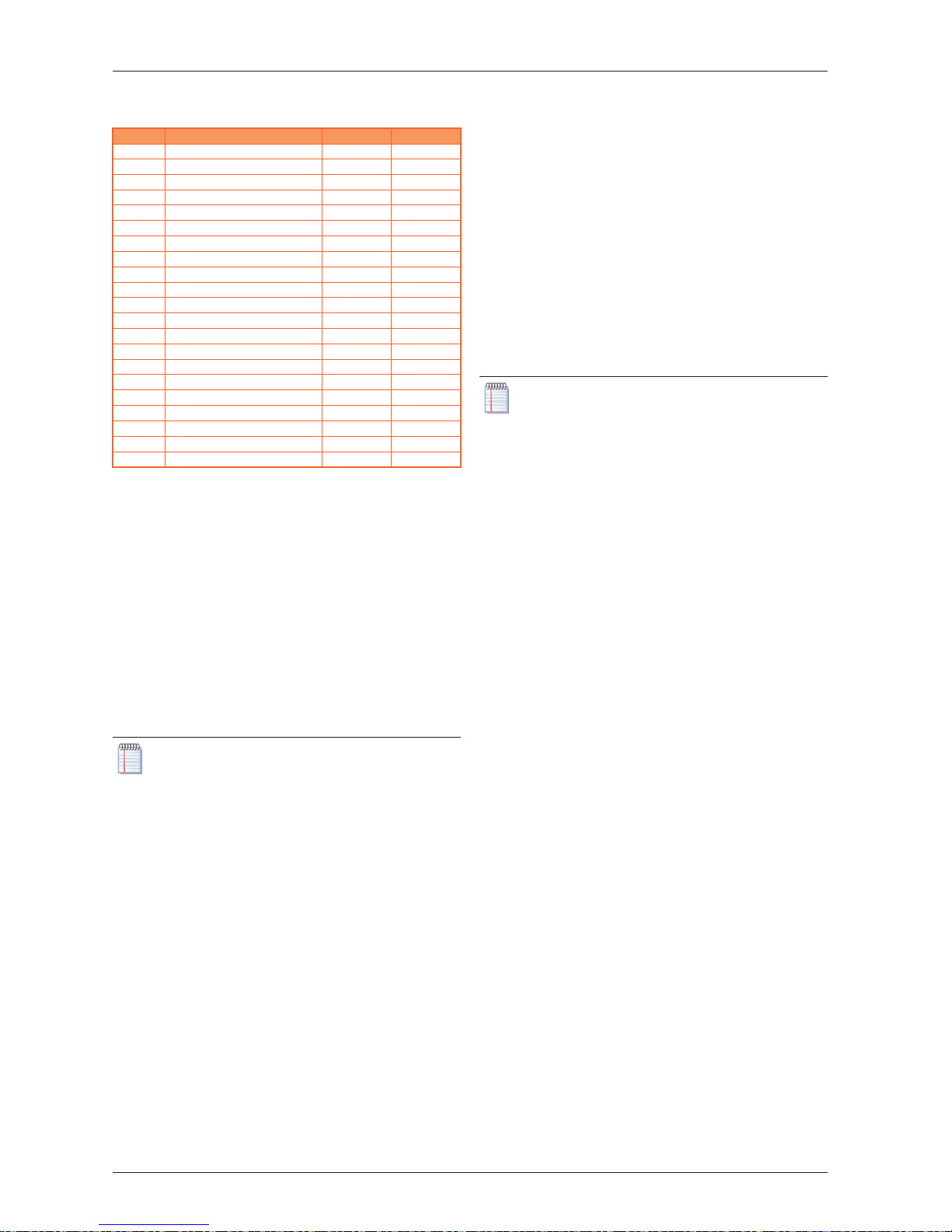
Table 6.1
p. 21
lists the error codes, with descriptions and
priorities, which can be generated by the K18 system controller,
with Expansion kit installed, when it is congured to support the
circuits indicated in this manual; The last column of the table
lists measures for resolving the problem.
Page 21
Errors
Installation manual – Expansion kit
21
6
Table6.1 List of K18 system controller error with expansion kit installed
Code Description Priority Action
10 Outside sensor B9 6 A
30 Flow sensor 1 (1) 6 A
32 Flow sensor 2 (6) 6 A
50 DHW sensor 1 (2) 6 A
60 Room sensor 1 (3) 6 B
65 Room sensor 2 (4) 6 B
68 Room sensor 3 (7) 6 B
83 BSB, short-circuit (5) 8 C
84 BSB, address collision 3 D
103 Communication failure 3 C
127 Legionella temp 6 E
324 BX same sensors 3 F
330 BX1 no function 3 G
331 BX2 no function 3 G
332 BX3 no function 3 G
333 BX4 no function 3 G
441 BX31 no function 3 G
442 BX32 no function 3 G
443 BX33 no function 3 G
444 BX34 no function 3 G
173 Active alarm 3 contact 6 H
(1) Probe B1
(2) Probe B3
(3) Room unit 1
(4) Room unit 2
(5) Shown in this form in the error log (see par. 6.2
p.22
). The information
screen displays the text "No connection" without error code.
(6) Probe B12
(7) Room unit 3
6.1.1 Troubleshooting measures
A: Codes 10, 30, 32, 50
For codes 10, 30, 50 refer to Paragraph 6.1 of the System Controller Installation manual. For code 32, proceed as follows:
1. Memorize the sensors:
Access the Engineer menu level, then the Congura-
tion menu; select parameter 6200 (Save sensors),
set it to yes and conrm.
The value of parameter 6200 which displays at the end
of the conguration procedure will still be no; this is
normal (this setting executes an action, i.e. memorization of the actually installed sensors).
Wait for a minute.
2. If step 1 does not resolve the problem:
Check the connection of the sensor in question, cor-
rect it and memorize the sensor again as indicated in
step 1.
3. If step 2 does not resolve the problem:
Disconnect the sensor from the RVS21.826 controller
and measure the resistance between the cable's two
wires. If the measurement indicates a short or open
circuit, identify and resolve the problem, which may
be due to the sensor itself or its wiring. Once the
problem has been resolved, reconnect the sensor and
memorize it again as indicated in step 1.
4. If step 3 does not resolve the problem:
Access the Engineer menu level, then the Congu-
ration menu; select parameter 6391 (Sensor input
BX31); check that it is set to the value used by parameter 6455; if not, remaining in the Engineer menu
level, Conguration menu, select parameter 6455
(Function mixing group 3) and set it to Heating circuit 2.
Run sensor memorization again as indicated in step 1.
ATTENTION: This sensor is used only in the presence of
the mixed heating circuit 2, otherwise no
sensor must be connected to input BX31.
If a sensor is connected to this input by mistake, remove it, then run sensor memorisation again as described in step 1.
5. If step 4 does not resolve the problem:
Power the system controller o and on again; if the
problem persists, contact the Robur Technical Support Centre.
B: Codes 60, 65, 68
1. Memorize the sensors:
Access the Engineer menu level, then the Congura-
tion menu; select parameter 6200 (Save sensors),
set it to yes and conrm.
The value of parameter 6200 which displays at the end
of the conguration procedure will still be no; this is
normal (this setting executes an action, i.e. memorization of the actually installed sensors).
Wait for a minute.
2. If step 1 does not resolve the problem:
Check the communications between the controller
and the room unit/s and their conguration (see par.
5.1.7
p.19
). Resolve the problem, then run sensor
memorization again as indicated in step 1.
3. If step 2 does not resolve the problem:
Power the system controller o and on again; if the
problem persists, contact the Robur Technical Support Centre.
C: Codes 83, 103
Refer to Paragraoh 6.1 of the System Controller Installation
manual.
D: Code 84
This problem occurs when multiple room units are connected
and some of them are congured as the same type of device
(e.g., two room units both as room unit 1).
1. Resolve the problem as indicated in par. 5.1.7
p.19
, Case
3, to congure the room units correctly.
2. If step 1 does not resolve the problem:
Power the system controller o and on again; if the
problem persists, contact the Robur Technical Support Centre.
E: Code 127
Refer to Paragraoh 6.1 of the System Controller Installation
manual.
F: Code 324
This error is generated if two or more BX temperature sensors
have been congured to a single function.
1. Check the conguration:
Access the Engineer menu level, then the Congura-
tion menu, and select parameters:
- 6014 ( Function mixing group 1); set it to
Multifunctional.
- 5930 (Sensor input BX1); check that it is set to
Outside sensor B9; if not, set it to that value.
- 5931 (Sensor input BX2); check that it is set to
none; if not, set it to this value.
- 5932 (Sensor input BX3); check that it is set to
DHW sensor B3; if not, set it to this value.
- 5933 (Sensor input BX4); set it to none.
Page 22

Special operations and configurations
22
7
- 6014 ( Function mixing group 1); set it to Heating circuit 1.
- 6455 ( Function mixing group 3); set it to
Multifunctional.
- 6391 (Sensor input BX31); check that it is set to
none; if not, set it to this value.
- 6392 (Sensor input BX32); check that it is set to
none; if not, set it to this value.
- 6393 (Sensor input BX33); check that it is set to
none; if not, set it to this value.
- 6394 (Sensor input BX34); check that it is set to
none; if not, set it to this value.
- 6455 ( Function mixing group 3); set it to Heating circuit 2.
Run sensor memorization: access the Engineer menu
level, thent the Conguration menu; select parameter 6200 (Save sensors), set it to yes and conrm.
The value of parameter 6200 which displays at the end
of the conguration procedure will still be no; this is
normal (this setting executes an action, i.e. memorization of the actually installed sensors).
Wait for a minute.
2. If step 1 does not resolve the problem:
Power the system controller o and on again; if the
problem persists, contact the Robur Technical Support Centre.
G: Codes 330, 331, 332, 333, 441, 442, 443, 444
This problem is due to the physical presence of a sensor connected to one of inputs BX1, BX2, BX3, BX4, BX31, BX32,
BX33, BX34, to which no function is assigned.
For codes 330, 331, 332, 333 refer to Paragraph 6.1 of the System
Controller Installation manual. For codes 441, 442, 443, 444 proceed as follows:
1. Check the conguration:
a. for code 441:
- Access the Engineer menu level, then the Cong-
uration menu; select parameter 6391 (Sensor input BX31); check that it is set to the value used by
parameter 6455; if not, remaining in the Engineer
menu level, Conguration menu, select parameter 6455 (Function mixing group 3) and set it to
Heating circuit 2.
b. for codes 442, 443, 444:
- remove the sensor connected respectively to input
BX32, BX33, BX34 (unassigned inputs).
Run sensor memorization: access the Engineer menu
level, thent the Conguration menu; select parameter 6200 (Save sensors), set it to yes and conrm.
The value of parameter 6200 which displays at the end
of the conguration procedure will still be no; this is
normal (this setting executes an action, i.e. memorization of the actually installed sensors).
Wait for a minute.
2. If step 1 does not resolve the problem:
Power the system controller o and on again; if the
problem persists, contact the Robur Technical Support Centre.
H: Code 173
Refer to Paragraoh 6.1 of the System Controller Installation
manual.
6.2 ERROR LOG
Refer to Paragraph 6.2 of the System Controller Installation
manual.
7 SPECIAL OPERATIONS AND CONFIGURATIONS
Refer to section 7 of the system controller Installation manual.
Page 23

Appendix A: technical data
Installation manual – Expansion kit
23
7
APPENDIX A: TECHNICAL DATA
RVS21.826, QAA75.611, QAA55.110
Refer to Appendix A of the system controller Installation manual.
AVS55.196
Table AVS55.196 technical data
Power supply
Supply voltage AC 230 V (+10%/-15%)
Frequency 50 / 60 Hz
Consumption max. 2.5 VA
Power supply protection
Thermal-magnetic circuit breaker: max. 13 A (EN60898-1)
or
fuse: max. 10 AT
Cabling
230 VAC supply and outputs; bars or braided
cables (with/without terminals)
1cable: 0.5 - 2.5 mm²
2cables: 0.5 - 1.5 mm²
Inputs
Digital inputs H31, H32, H33
Open contact voltage
Closed contact current
Safety Extra Low Voltage (SELV) for voltage free contacts
DC 12 V
DC 3 mA
Analogue inputs H31, H32, H33
• Functional range
• Internal resistance
Safety Extra Low Voltage (SELV)
DC 0 - 10 V
> 100 kΩ
Pulse count inputs H31, H32, H33
• Open contact voltage
• Closed contact current
• Pulse duration
Safety Extra Low Voltage (SELV) for voltage free contacts
DC 12V
DC 3 mA
min. 20 ms
Frequency measurement inputs H31, H32, H33
• Functional range
• Low state voltage
• High state voltage
• Internal resistance
• Frequency
Safety Extra Low Voltage (SELV)
DC 0 - 12 V
< 1.7 V
2.7 - 12 V
> 100 kΩ
max. 500 Hz
Sensor inputs BX31 - BX34
NTC 1k (QAC34, external sensor),
NTC 10k (QAZ36, QAD36),
Pt1000 (optional for solar collector and exhaust gas sensor)
5053…9671 Ω (room setpoint modication function)
Sensor cables (copper)
• Cross section
• Max. length
-
0.25 0.5 0.75 1.0 1.5 (mm²)
20 40 60 80 120 (m)
Outputs
Relay outputs QX31…QX33, QX35
• Current range
• Switching ON current
• Total current
AC 0.02 - 2 (2) A
max. 15 A for ≤1 s
max. AC 10 A (total, all 230 VAC outputs)
Triac output ZX34
• Current range
• Switching ON current
• Total current
AC 0.02 - 2 (2) A (On/O operation); AC 0.02 - 1.2 (1.2) A (speed control)
max. 4 A for ≤1 s
max. AC 10 A (total, all 230 VAC outputs)
Power G+
• Output voltage
• Current
Safety Extra Low Voltage (SELV), outputs with short-circuit protection
11.3 - 13.2 V
max. 88 mA (including RVS21 and AVS55)
Power GX1 (congurable)
• Output voltage 5 V
• Output voltage 12 V
• Current
Safety Extra Low Voltage (SELV), outputs with short-circuit protection
4.75 - 5.25 V
11.3 - 13.2 V
max. 20 mA (including RVS21 and AVS55)
Interfaces
BSB
Base unit/peripheral cable length
Total cable length
Cross section
Two-wire connection (not invertible)
max. 200 m
max. 400 m (max. cable capacity: 60 nF)
min. 0.5 mm²
Connection cable X100 to expansion module
AVS55.19x
• Cable length
ribbon cable (18 pole)
max. 1000 mm
Protection rating and
safety class
Enclosure protection rating per EN60529 IP 00 (without enclosure)
Safety class per EN60730 safety class II for LV parts, if correctly installed
Degree of contamination per EN60730 degree of contamination normal
Standards, safety, EMC, etc. CE conformity (EU) CE1T2355xx06
Climatic conditions
Storage, per EN60721-3-1
Transport, per EN60721-3-2
Operation, per EN60721-3-3
class 1K3, -20 - 65 °C
class 2K3, -25 - 70 °C
class 3K5, -20 - 50 °C (non condensing)
Weight Packaging excluded 112 g
Page 24

Robur S.p.A.
advanced technologies
for climate conditioning
via Parigi 4/6
24040 Verdellino/Zingonia (BG) Italy
+39 035 888111 - F +39 035 884165
www.robur.it [email protected]
10/03/2017
17MEDSDC006
Code: D-LBR809
Revision: A
Robur mission
Robur is dedicated to dynamic progression
in research, development and promotion
of safe, environmentally-friendly, energy-eciency products,
through the commitment and caring
of its employees and partners.
 Loading...