

Page 1
Installation, user and
maintenance manual
AY Condensing line, AY Series
gas red
4 star condensation boiler
for heating
Page 2

Revisione: J
Codice: D-LBR531
This manual has been drawn up and printed by Robur S.p.A.; whole or partial reproduction of this manual is
prohibited.
The original is led at Robur S.p.A.
Any use of this manual other than for personal consultation must be previously authorised by Robur S.p.A.
The rights of those who have legitimately led the registered trademarks contained within this publication are not
aected.
With the aim of continuously improving the quality of its products, Robur S.p.A. reserves the right to modify the
data and contents of this manual without prior notice.
Page 3

Installation, user and maintenance manual – AY Condensing line, AY Series
3
INDEX OF CONTENTS
1 PREFACE �������������������������������������������������������������������������������������������������������������������������������������������������� 4
2 SAFETY WARNINGS �������������������������������������������������������������������������������������������������������������������������������� 5
3 OVERVIEW AND TECHNICAL FEATURES ���������������������������������������������������������������������������������������������� 7
3.1 GENERAL INFORMATION ..........................................................................................................................................................................................7
3.2 OVERVIEW OF OPERATION ......................................................................................................................................................................................8
3.3 TECHNICAL MANUFACTURING CHARACTERISTICS .........................................................................................................................................9
3.4 TECHNICAL DATA ........................................................................................................................................................................................................9
3.5 DIMENSIONS AND SERVICE PANEL ....................................................................................................................................................................11
4 NORMAL OPERATION �������������������������������������������������������������������������������������������������������������������������� 13
4.1 START UP (AND SHUT DOWN) .............................................................................................................................................................................13
4.2 ON-BOARD ELECTRONICS ..................................................................................................................................................................................... 14
4.3 RESET OPERATIONS .................................................................................................................................................................................................15
4.4 OPERATING SETTINGS ............................................................................................................................................................................................ 16
4.5 PROLONGED PERIODS OF DISUSE ..................................................................................................................................................................... 17
5 HYDRAULIC INSTALLATION ���������������������������������������������������������������������������������������������������������������� 18
5.1 GENERAL INSTALLATION PRINCIPLES ............................................................................................................................................................... 18
5.2 POSITION OF THE APPLIANCE ............................................................................................................................................................................. 18
5.3 HYDRAULIC CONNECTIONS ................................................................................................................................................................................. 19
5.4 GAS SUPPLY ................................................................................................................................................................................................................23
5.5 CONDENSATE DISCHARGE .................................................................................................................................................................................... 24
5.6 FILLING THE SYSTEM CIRCUIT (APPLIANCE) ...................................................................................................................................................25
5.7 FILLING THE APPLIANCE’S INTERNAL CIRCUIT ..............................................................................................................................................25
5.8 EXHAUST FLUE GAS .................................................................................................................................................................................................26
5.9 PROGRAMMING OF HYDRAULIC PARAMETERS.............................................................................................................................................29
6 ELECTRICAL INSTALLATION ���������������������������������������������������������������������������������������������������������������32
6.1 CONNECTING THE APPLIANCE TO THE MAINS .............................................................................................................................................. 34
6.2 ELECTRICAL CONNECTIONS FOR THE SYSTEM CIRCULATOR ................................................................................................................... 36
6.3 CONNECTIONS FOR CONSENT SWITCH OPERATION ................................................................................................................................... 39
6.4 USE OF THE CCI/DDC ..............................................................................................................................................................................................40
7 INITIAL ACTIVATION AND MAINTENANCE ����������������������������������������������������������������������������������������50
7.1 PROCEDURE FOR FIRST START UP ......................................................................................................................................................................50
7.2 MAINTENANCE .......................................................................................................................................................................................................... 53
7.3 CHANGE OF GAS TYPE............................................................................................................................................................................................54
8 ACCESSORIES ��������������������������������������������������������������������������������������������������������������������������������������� 58
9 OPERATING CODES/TROUBLESHOOTING ����������������������������������������������������������������������������������������� 59
9.1 OVERVIEW AND OPERATING CODES/TROUBLESHOOTING .......................................................................................................................59
Page 4

1 PREFACE
4
1 PREFACE
This "Installation, user and maintenance manual" is a guide to the installation and operation of the AY Condensing Line base-mounted
gas boiler.
In particular, the manual deals with the AY00-120 model, hereinafter called "appliance", of the AY Series, and is intended for use by:
▶
nal users for the operation of the appliance according to their own requirements;
▶
installation technicians (hydraulic and electrical) for the carrying out of a correct installation of the appliance and of the Direct
Digital Controller (DDC).
The manual also contains:
▶
a section that describes all the operations necessary for the “rst start-up” and for the “gas change” of the appliance, as well as the
main maintenance operations;
▶
an "ACCESSORIES" section with a description of accessories available and their respective reference codes;
▶
(IN CASE) one or more APPENDIX sections in which are reported some "specic" information for a particular country.
Denitions, meaning of terms and icons
APPLIANCE: 4 star condensation boiler, Robur model "AY00-120".
CCI: "Comfort Control Interface" device. Not applicable.
DDC: digital control panel (Direct Digital Controller).
TAC: Technical Assistance Centre (authorised by Robur S.p.A.).
ACS: sanitary (domestic) hot water.
UTA: air handler.
The icons used in the manual have the following meanings:
= DANGER
= WARNING
= NOTE
= START OF OPERATING PROCEDURE
= REFERENCE to another part of the manual or other document
Page 5
2 SAFETY WARNINGS
Installation, user and maintenance manual – AY Condensing line, AY Series
5
2 SAFETY WARNINGS
Packing items (plastic bags, polystyrene foam, nails, etc.) must be kept out of the reach of children, as they are potentially
dangerous.
The appliance must only be used for the purposes for which it has been designed. Any other use is considered inappropriate
and therefore dangerous. The manufacturer does not accept any contractual or extra-contractual liability for any damage
caused by improper use of the appliance.
Frequent topping up of the hydraulic with water can result in damage due to scale and corrosion, depending on the quality
of the water being used. Make sure the system is water tight and that the expansion tank is operational.
Concentrations of chlorides or free chlorine in the circuit above the values given in Table 5.1→19 will damage the unit's
water/ammonia exchanger.
Close the gas supply before working on the gas circuit. On completing work on the gas circuit, check for leakages as required
by established regulations.
Do not operate the appliance if dangerous conditions exist: odour of gas in the grid or near the appliance; problems with the
electrical/gas grid or hydraulic circuit; parts of the appliance submerged in water or otherwise damaged; controls or safety
components bypassed or defective. In these cases, ask for assistance to professionally qualied personnel.
If you smell gas:
▶
do not use electrical devices such as telephones, multimeters or other equipment that can cause sparks next to the appliance;
▶
shut o gas supply closing the isolation valve;
▶
cut o electrical power opening the main breaker upstream of the appliance (to be provided by the electrical installer in an appropriate panel);
▶
ask for assistance to professionally qualied personnel from a telephone distant from the appliance.
Moving parts, also during the appliance's start-up and shut-down cycles. Do not remove guards. Make sure the appliance
cannot be started up inadvertently.
POISONING HAZARD
Make sure the ue gas components are tight and compliant with established regulations. After any intervention on these parts,
check for tightness.
BURN HAZARD
The appliance contains numerous hot parts. Do not open up the appliance or touch the fumes outlet pipe. If necessary, contact your
Technical Assistance Centre.
ELECTROCUTION HAZARD
▶
Use only approved components for the electrical connections, as specied by the manufacturer.
▶
Disconnect the electrical power supply before working on the appliance's internal electrical equipment (electrical panel, motors,
control board, etc.).
▶
Make sure the appliance cannot be started up inadvertently.
The electrical safety of the appliance is ensured only when it is correctly connected to an ecient grounding system, compilant with current safety regulations.
DAMAGE DUE TO AGGRESSIVE SUBSTANCES IN THE AIR SUPPLY
Hydrogenated hydrocarbons, which contain chlorine and uorine compounds, will increase the corrosion of the unit.
Make sure the air supply is free of aggressive substances.
ACID CONDENSATE
Drain out the condensate produced during combustion as indicated in paragraph 5.5→24.
EXPLOSIVE/FLAMMABLE MATERIALS HAZARD
Do not use or store ammable materials (paper, solvents, paint, etc.) in the vicinity of the appliance.
SUGGESTIONS FOR THE CLIENT
Page 6

2 SAFETY WARNINGS
6
Stipulate a maintenance contract with an authorised specialist contractor for the annual inspection of the appliance and maintenance when needed.
Maintenance and repairs may only be done a contractor legally authorised to work on gas appliances and equipment.
Only accept and use original spare parts.
Page 7

3 OVERVIEW AND TECHNICAL FEATURES
Installation, user and maintenance manual – AY Condensing line, AY Series
7
3 OVERVIEW AND TECHNICAL FEATURES
In this section you will nd general information, hints on the operating principle of the appliance and its manufacturing features. This
section also contains technical data and dimensional drawings of the appliance.
3.1 GENERAL INFORMATION
This manual is an integral and essential part of the product and must be delivered to the user together with the appliance.
Conformity to CE standards
The appliance is CE certied and conforms with all essential requirements of:
▶
Gas Directive 90/396/EEC and subsequent modications and additions.
▶
Eciency Directive 92/42/EEC and subsequent modications and additions.
▶
Electromagnetic Compatibility Directive 89/336/EEC and subsequent modications and additions.
▶
Low Voltage Directive 89/336/EEC and subsequent modications and additions.
▶
Machinery Directive 2006/42/EC.
▶
UNI EN 677 Specic requirements for condensing boilers with nominal thermal capacity up to 70 kW.
▶
UNI EN 483 Type C boilers with nominal thermal capacity no greater than 70 kW.
Information regarding the above EC certications is given in Paragraph 3.4→9, as well as on the Nameplate of the appliance itself.
Installation and regulatory references
When the appliance arrives at the installation site, before beginning the stages required to move it in order to position it on the site,
perform a visual check to ascertain that there are no evident signs of breakage or damage to the packaging or to the external panels,
which would be signs that damage occurred during transport.
Packing materials must be removed only after the appliance has been positioned on site. After removing the packing materials, ensure that the appliance is intact and complete.
Installation of the appliance may only be carried out by professionally qualied personnel by i.e. rms qualied according to the current legislation of the country of installation.
"Professionally qualied personnel" means personnel with specic technical competence in the sector of heating/cooling
installations and gas appliances.
Installation of the appliance must be carried out in compliance with current local and national regulations regarding the design,
installation and maintenance of heating and cooling installations and in accordance with the manufacturer's instructions.
In particular, current regulations regarding the following must be observed:
▶
Gas equipment.
▶
Electrical equipment.
▶
Heating systems employing condensation boilers.
▶
Every other standard and regulation concerning the installation of equipment for summer and winter air conditioning using gas
fuel.
The manufacturer does not accept any contractual or extra-contractual liability for any damage caused by errors in installation and/
or failure to observe the abovementioned regulations and the instructions supplied by the manufacturer itself.
Once the appliance is installed
The installer must provide the owner with a Declaration stating that the installation has been completed in compliance with
state-of-the-art practices, current national and local regulations, and recommendations by the manufacturer.
Before contacting your authorised Robur Technical Assistance Centre (TAC) for the initial activation, the rm must ensure that:
▶
the electricity and gas mains specications correspond to the specications on the nameplate;
▶
the gas supply pressure is compliant with the value reported in Table 5.2→24 (considering a tolerance of ±15%);
▶
the appliance is fed by the type of gas for which it is designed;
▶
the gas supply system and water distribution system are sealed;
▶
the gas and electricity supply systems are properly rated for the capacity required by the appliance and are equipped with all
safety and control devices required by current regulations
Check that no safety and control devices are excluded, by-passed or not properly working.
Initial activation procedure
The complete procedure for the rst start up of the appliance must be carried out by an authorized technician according to the
instructions supplied by the manufacturer.
To carry out entire procedure correctly, follow the instructions in Paragraph 7.1→50.
Warranty could be invalidated if the rst start up is not carried out and validated by an authorized technician.
Page 8
3 OVERVIEW AND TECHNICAL FEATURES
8
Operation and maintenance of the appliance
To ensure the correct operation of the appliance and to avoid failures, control of the switching on and o of the appliance must be
carried out exclusively via a switch located on the on/o command circuit.
If the appliance is to be connected to a Direct Digital Controller (DDC, available as an accessory), control of activating and deactivating the appliance must be performed exclusively through the DDC itself.
The appliance must never normally be switched on and o by shutting o the power supply upstream of the on/o commands (DDC or other switch) before having operated these rst. With the appliance running, also wait for the shutdown
cycle to end (approximately 3 minutes) before shutting o the power supply power.
If the appliance fails to operate correctly, with the consequent indication of the Machine code, follow the instructions of Paragraph
9.1→59.
In the event of failure of the appliance and/or breakage of any component, do not attempt to repair and/or restore opera-
tion; proceed as follows:
▶
deactivate the appliance immediately (if permitted and if no condition of danger exists) by starting the shutdown cycle via the
on/o command (or DDC) and waiting for it to terminate (approximately 3 minutes);
▶
disconnect the appliance from the gas and electricity mains, cutting o gas supply by means of the appropriate valve and the
power supply by means of the external circuit breaker provided by the electrical system installation technician on the appropriate panel;
▶
contact your local Robur TAC.
If it is decided not to use the appliance for a prolonged period, disconnect the appliance following the instructions provided in
Paragraph 4.5→17.
Proper ordinary maintenance ensures the eciency and good operation of the appliance over time.
Carry out maintenance operations according to the instructions supplied by the manufacturer (see Paragraph 7.2→53).
For maintenance of the appliance’s internal components, contact a Robur TAC or qualied technician; for other maintenance requirements, see Paragraph 7.2→53.
Any repair of the appliance must be carried out by Technical Assistance, using only original spare parts.
Failure to observe the indications given above may compromise the operation and safety of the appliance, and may invalidate its guarantee, if active.
If the appliance is to be disposed of, contact the manufacturer for its correct disposal.
If the appliance is to be sold or transferred to another owner, ensure that this “Installation, user and maintenance manual” is
handed over to the new owner and installer.
3.2 OVERVIEW OF OPERATION
The appliance powered by 230 V 1N 50 Hz electrical power - .
During operation, combustion products are exhausted via the discharge terminal, with vertical outlet, at the top of the appliance.
Combustion product condensate is discharged via the special pipe which passes through the service plate (see Figure 3.3→12).
The appliance is equipped with a plate exchanger which separates the following hydraulic circuits:
▶
the internal circuit dedicated to the combustion unit and factory charged to enable storage down to -30°C;
▶
the system circuit. The section of circuit running from the exchanger to the hydraulic unions on the service plate is itself a part
of the system circuit.
Control and management of operation of the appliance occurs via the on-board electronics through the microprocessor control
board (see Figure 4.1→14).
Control and management of operation of the appliance may also take place via the Direct Digital Controller (see Figure 3.1→9) available as an accessory.
For instructions regarding the use, conguration and programming of the DDC, refer to the two manuals supplied with the
unit.
DDC conguration/programming operations must be carried out by an authorised Robur Technical Assistance Centre (TAC)
during initial activation procedures and according to the instructions supplied by the manufacturer.
Page 9
3 OVERVIEW AND TECHNICAL FEATURES
Installation, user and maintenance manual – AY Condensing line, AY Series
9
Figure 3.1 – CCI/DDC
AY00-120: description and general characteristics
the appliance (see Figure 3.2→11) is a B53P type high eciency boiler ( star eciency class as per Directive 92/42/CEE).
The appliance is a Range Rated boiler: the power delivery of the appliance can be adapted to the real system requirements by regulating the nominal gas ow (nominal thermal input).
The appliance, which can produce hot water up to 80°C, is suited to installation in all hot water production systems for heating, sanitary use (ACS), process needs, air handlers, etc. Since the appliance is of the 2 pipe variety (water inlet and outlet), it can be adapted
to a variety of purposes (e.g.: both heating and ACS) by bleeding the system.
3.3 TECHNICAL MANUFACTURING CHARACTERISTICS
The appliance is supplied with the following technical manufacturing characteristics, control and safety components:
▶
premixed multigas burner with low NOX and CO emissions;
▶
stainless steel plate exchanger, acting as a hydraulic separator;
▶
AY10 microprocessor controller with LCD display and control knob (Figure 4.1→14);
▶
S70 controller (Figure 4.1→14);
▶
ionisation-based ame controller;
▶
gas solenoid valve with double shutter;
▶
system water antifreeze function;
▶
internal circuit antifreeze function;
▶
automatically resettable water temperature limiting thermostat;
▶
single-use fumes limiting thermostat (thermal cutout);
▶
system circuit water dierential pressure switch (PD1);
▶
internal circuit water dierential pressure switch (PD2) with anti-sticking function;
▶
overpressure valve on internal circuit, set to trip at 3 bar;
▶
internal circuit expansion tank;
▶
automatic and manual air bleeds on the internal circuit;
▶
fumes pipe with terminal, for type B53P conguration.
▶
condensate discharge siphon (with antifreeze function);
▶
anti-freezing thermostat used for the activation of the heating element on the condensate drain.
3.4 TECHNICAL DATA
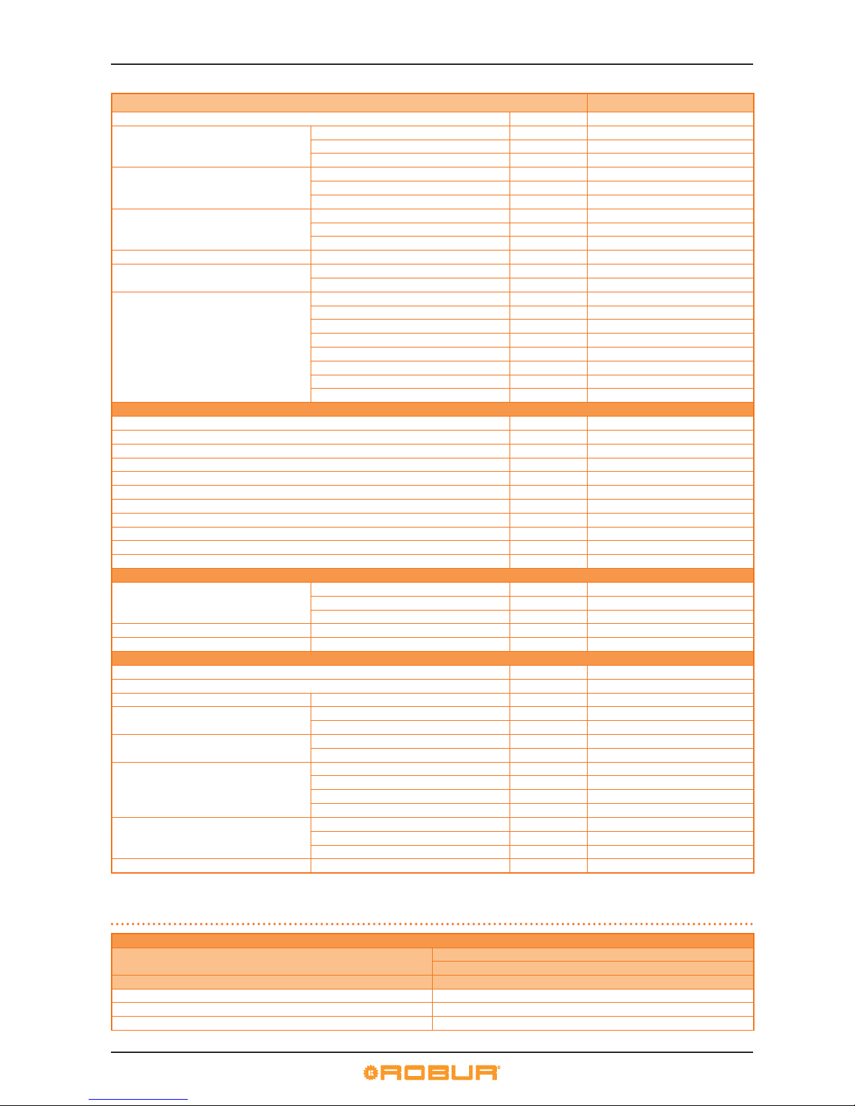
Table 3.1 – TECHNICAL CHARACTERISTICS
AY00-120
OPERATION WHEN HEATING
Thermal capacity
Nominal (1013 mbar - 15°C) kW 34,9
MEAN kW 21.5
MIN kW 8.0
OPERATING POINT: Tm80/Tr60 and nominal thermal
capacity
Available power kW 34.4
Eciency % 98.6
OPERATING POINT: Tm80/Tr60 and minimal thermal
capacity
Eciency % 97.3
OPERATING POINT: Tm70/Tr50 and nominal thermal
capacity
Eciency % 100,6
Eciency classes ****
Page 10
3 OVERVIEW AND TECHNICAL FEATURES
10
AY00-120
NOx emission class 5
Hot water delivery temperature
maximum °C 80
minimum °C 25
nominal °C 60
Hot water return temperature
maximum °C 70
minimum °C 20
nominal °C 50
Hot water ow rate
nominal l/h 2950
maximum l/h 3200
minimum l/h 1500
Hot water pressure drop at nominal water ow bar 0,395
Ambient air temperature (dry bulb)
maximum °C 45
minimum °C -20
gas consumption
methane G20 (nominal) m3/h 3.69
methane G20 (MIN) m3/h 0.85
G25 (nominal) m3/h 4,35
G25 (MIN) m3/h 1,00
G30 (nominal) kg/h 2.75
G30 (MIN) kg/h 0.63
G31 (nominal) kg/h 2.71
G31 (MIN) kg/h 0.62
THERMAL EFFICIENCIES
Eciency at MEAN thermal capacity Tm80/Tr60 % 98.3
Eciency at MIN thermal capacity Tm80/Tr60 % 97.3
Eciency at nominal thermal capacity Tm50/Tr30 % 104.6
Eciency at 30% of nominal thermal capacity Tr=30°C % 107.5
Eciency at 30% of nominal thermal capacity Tr=47°C % 100.3
Operational heat loss to jacket kW 0,15
Operational heat loss to jacket % 0.44
Operational heat loss to ue kW 0,86
Operational heat loss to ue % 2.54
Heat loss in o mode kW 0,058
Heat loss in o mode % 0,2
ELECTRICAL SPECIFICATIONS
Power supply
Voltage V 230
TYPE single-phase
Frequency 50 Hz supply 50
Electrical power absorption nominal kW 0.185
Degree of protection IP X5D
INSTALLATION DATA
Minimum storage temperature °C -30
Maximum operating pressure bar 3
Water content inside the apparatus HOT SIDE l 1,0
Water tting
TYPE F
thread " G 1 1/4
Gas tting
TYPE M
thread " G 3/4
Fume outlet
Type of installation B23P-B33-B53P-C13-C33-C43-C53-C63-C83
Diameter (∅) mm 80
Residual head Pa 100
Product conguration B53P
Size
width mm 410
height mm 1280
depth mm 530
Weight In operation kg 71
AY00-120 operational and installation technical characteristics.
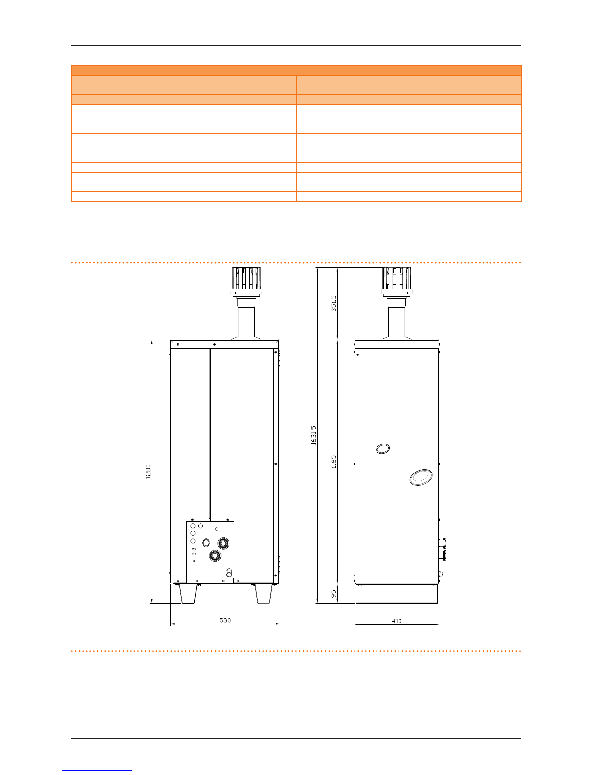
Table 3.2 – Table of pressure drop of a single unit - AY serie
PRESSURE DROP OF A SINGLE AY00-120 CONDENSING UNIT
Water ow rate
WATER TEMPERATURE
20°C
[l/h] [bar]
1008 0,066
1198 0,085
1398 0,106
Page 11
3 OVERVIEW AND TECHNICAL FEATURES
Installation, user and maintenance manual – AY Condensing line, AY Series
11
PRESSURE DROP OF A SINGLE AY00-120 CONDENSING UNIT
Water ow rate
WATER TEMPERATURE
20°C
[l/h] [bar]
1608 0,136
1801 0,165
2007 0,204
2199 0,234
2400 0,269
2601 0,312
2797 0,353
2958 0,395
3000 0,406
3201 0,469
3.5 DIMENSIONS AND SERVICE PANEL
Figure 3.2 – Dimensional drawing of model AY00-120
AY00-120 - front and RH side views (dimensions in mm).
LEGEND
Series AY model AY00-120
Page 12
3 OVERVIEW AND TECHNICAL FEATURES
12
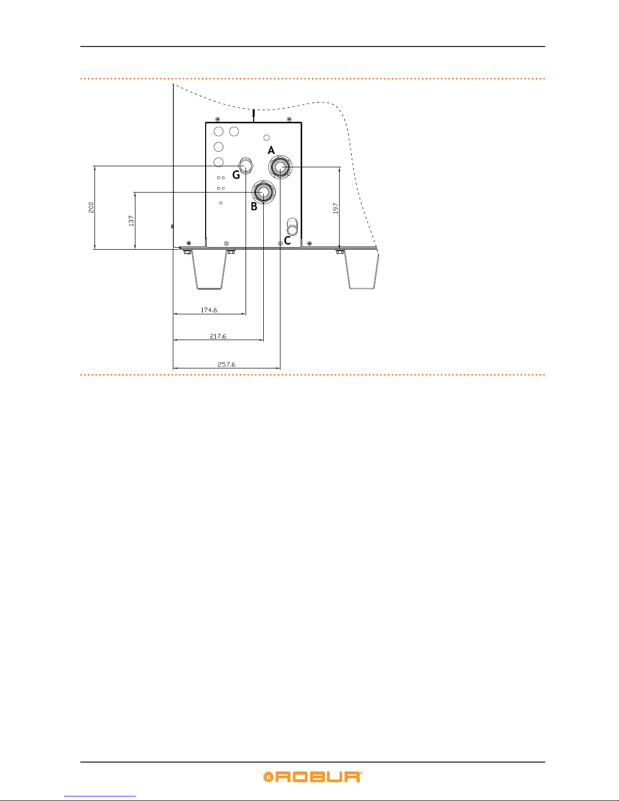
Figure 3.3 – SERVICE PANEL: Series AY - AY Condensing line
Series AY - service plate (dimensions in mm).
LEGEND
G gas tting ("G 3/4 M)
A outlet water tting ("G 1 1/4 F)
B inlet water tting ("G 1 1/4 F)
C condensate drain tting (ext. dia. 25 mm)
Page 13
4 NORMAL OPERATION
Installation, user and maintenance manual – AY Condensing line, AY Series
13
4 NORMAL OPERATION
In this section you will nd all the indications necessary for the activation, regulation and control of operation of the appliance via
the controller present in the electrical panel.
4.1 START UP AND SHUT DOWN
Ecient operation and long life of the appliance depend largely on its correct use!
Before activating the appliance, check that:
▶
the gas valve is open;
▶
the appliance is powered electrically: the general electrical switch (GS) must be in the «ON» position;
▶
the installation technician has ensured that the hydraulic circuit is supplied in the correct conditions.
If these conditions are satised, it is possible to proceed with activation.
If the appliance is not connected to a DDC, it may be activated and deactivated only by means of the on/o command provided by
the electrical installation technician.
According to requirements, this on/o command may be an on/o button, an ambient thermostat, a programmable timer, or one or
more voltage free contacts controlled by another process.
For details about the type of on/o command installed, contact the plant’s electrical installation technician.
Start up
Switch on the appliance by means of the on/o command (placing it in the "ON" position).
Shut down
Switch o the appliance via the on/o command (placing it in the "OFF" position).
The shutdown cycle takes approximately 3 minutes to complete.
The on/o command is essential! Do not switch the appliance on or o by connecting it to or disconnecting it from the
power supply directly, as this may be a source of danger and in any case damage the appliance or the plants connected to it.
If the appliance is connected to a DDC running in controller mode, the appliance is started up and controlled exclusively by
the DDC.
For instructions regarding the use of the DDC, refer to the two manuals supplied with it, and in particular: "Final user manual
- manual 2"
Visualising and clearing of operating codes
Operating codes can be generated by the controller or by the DDC.
The operating codes generated by the controller are visualised on its display and may also be visualised on the display of the DDC
(if tted).
Operating codes generated by the controller can be reset with the controller itself or from the DDC (if tted or where possible).
For a description of the operating codes generated by the electronic board and how to reset them, refer to the list of operating codes contained in Table 9.1→59.
The controller (see Figure 4.1→14) is located inside the electrical panel of the appliance and the display may be viewed
through the viewing hole on the front panel of the unit itself.
The Machine Codes generated by the DDC may only be viewed on the display of the DDC and may be cleared only through
the DDC.
Operating codes generated by the electronic board during the start-up of the appliance
If the appliance remains inactive for a prolonged period, it is possible that air is present in the gas pipes. In this case, activation fails
and the appliance reports the operating code: "u_12" - ame controller arrest (temporary) (see Paragraph 9.1→59) and after a brief
interval the appliance automatically launches the start up procedure again.
If code (u_12) is signalled 4 times on successive activation attempts, the code persists, the appliance locks out the ame controller
and displays the following operating code: "E_12" – ame controller arrest (see Paragraph 9.1→59). In this case reset is not automatic.
To restore operation of the appliance, carry out a reset of the ame control unit via menu 2 of the controller: the procedure is illustrated in Paragraph 4.3→15. After it is reset, the appliance will make a new attempt to activate.
If the appliance locks out several times, contact a Robur TAC by calling the Technical Service Department of Robur S.p.A. (tel.
+39.035.888111).
When activation is successful, the appliance is managed by the on-board controller (see following paragraph).
Page 14
4 NORMAL OPERATION
14
4.2 ONBOARD ELECTRONICS
The following descriptions refer to the controller with rmware version 3.106.
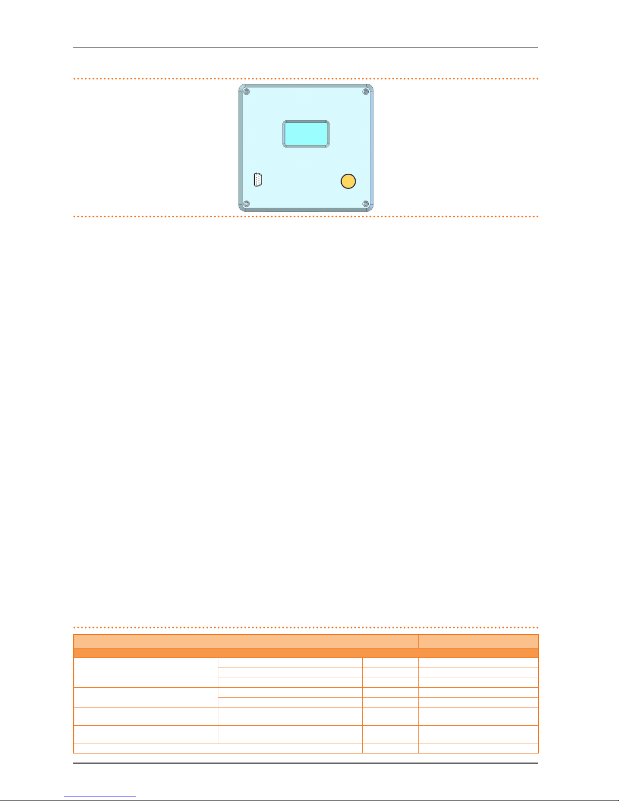
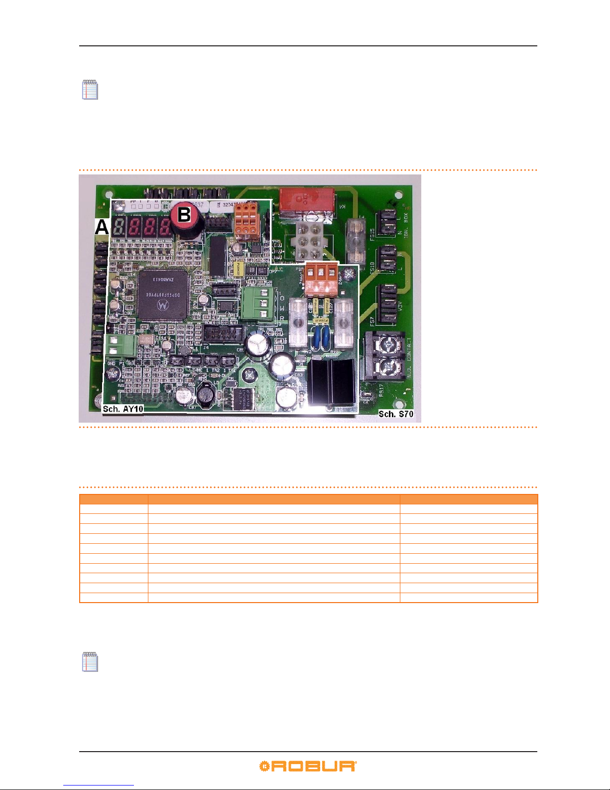
The appliance is tted with an AY10 controller connected to an auxiliary S70 controller (see Figure 4.1→14). The AY10 is installed over
the S70 and is located in the machine’s internal electrical panel.
The AY10 controller controls the appliance and displays data, messages and codes during operation. Programming, control and
monitoring of the appliance take place by interacting with the display and encoder of the controller. The CAN BUS port connects one
or several appliances to a DDC.
Figure 4.1 – On-board electronics
Controllers AY10 and S70.
LEGEND
A 4 digit display for data and
operating codes.
B Knob for scrolling through/
selecting operating data
Description of menu of AY10 controller
The parameters and settings of the appliance are grouped in the menus shown on the controller’s display:
Table 4.1 – Menu of electronic board
MENU MENU DESCRIPTION THE DISPLAY SHOWS
Menu 0 VIEW DATA (TEMPERATURE, VOLTAGE, PUMP SPEED, ECC...) 0.
Menu 1 VIEW ALL PARAMETERS 1.
Menu 2 ENTER ACTIONS 2.
Menu 3 USER SETTINGS (THERMOSTATING, SET-POINT, T. DIFFERENTIAL) 3.
Menu 4 INSTALLATION TECHNICIAN SETTINGS 4.
Menu 5 TECHNICAL ASSISTANCE CENTRE SETTINGS 5.
Menu 6 TECHNICAL ASSISTANCE CENTRE SETTINGS (MACHINE TYPE) 6.
Menu 7 VIEW DIGITAL IMPUTS 7.
Menu 8 (MENU NOT USED) 8.
E EXIT MENU E.
Menu list of electronic board
Menus 0, 1 and 7 are Viewing Menus: they only allow the information displayed to be read, and not modied. Menu 0 shows the appliance operating data in real time. Menu 1 shows the parameters that characterise the operation of the appliance and their current
values.
Menu 7 is to be used ONLY by the Robur TAC.
To view the information contained in these menus, proceed as illustrated in the procedure explained below: HOW TO ACCESS THE
MENUS.
Menu 2 is an Action Menu: it is used to reset the ame controller and errors.
To perform these procedures, see Paragraph 4.3→15.
Menu 3 is a Settings Menu: it allows the values displayed to be set. The correct values of these parameters, for optimum performance
of the appliance with the plant to be used connected, have already been set during installation. To set new values for the parameters,
see Paragraph 5.9→29.
Page 15
4 NORMAL OPERATION
Installation, user and maintenance manual – AY Condensing line, AY Series
15
Menus 4, 5, 6 and 7 exclusively concern the installation technician and Robur’s authorized Technical Assistance Centre.
Menu 8 may currently be selected, but not used.
Display and knob
The controller’s display can be viewed through the glass of the viewing aperture on the front panel of the appliance.
Upon activation, all display’s LED’s light up, and then the name of the controller displays. Subsequently (if the on/o command
switch is set to ON), the appliance begins to operate.
During correct operation the display shows, alternately, the following information: outlet water temperature, inlet water temperature, and the dierence between the two water temperatures (see Table 4.2→15).
Table 4.2 – Operating information
OPERATING MODE: HEATING
PARAMETER THE DISPLAY SHOWS
Hot outlet water temperature 50.0
Hot inlet water temperature 40.0
Dierential Temperature (outlet - inlet) 10.0
Example of data visualised on display: water temperature and dierential
If there are operating problems, the display shows, sequentially, the operating codes corresponding to the problem detected. A list
of these codes with their description and the procedure to follow to bring the appliance back to correct operation is provided in
Paragraph 9.1→59.
The knob is used to display or set parameters, or to execute actions/commands (e.g.: a function or reset), when permitted.
HOW TO ACCESS THE MENUS
▶
To use the knob with the special key supplied with the appliance:
You will need: the appliance's electrical power switches set to "ON"; the controller's display sequentially shows the operating data (temperature, delta T) regarding the current mode (e.g.: heating) and any active operating codes ("u/E...").
1. Remove the front panel by removing the xing screws.
2. Remove the cover of the electrical panel to access the knob.
3. Use the special key through the hole to operate the knob and access the controller’s menus and parameters.
4. To display the menus just press the knob once: the display shows the rst menu: "0." (= menu 0).
5. The display shows “0.”. To display the other menus, turn the knob clockwise; The display will read, in order: "1.", "2.", "3.", "4.", "5.",
"6.", "7.", "8." and "E" (see 4.1→14).
6. To display the parameters in a given menu (for example, menu 0), turn the knob until it displays the menu in question (in the
example: "0.") and press the knob: the display will show the rst of the menu’s parameters, in this example "0.0" or "0.40" (=
menu 0, parameter "0" or "40").
7. In the same way: turn the knob to scroll through content (menus, parameters, actions), press the knob to select/conrm the
content (access a menu, display/set a parameter, execute an action, quit or return to the previous level). For example, to quit
the menus, turn the knob to scroll through menus "0.", "1.", "2." etc. until the controller displays the quit screen "E"; now press
the knob to quit.
In the case of menus 0 and 1, the user can view any parameter. For how to access to menu 2, refer to Paragraph 4.3→15. To
set the parameters of me nu 3, refer to Paragraph 5.9→29. The other menus are not for the User: the information in these
menus is dealt with in the sections dedicated to the installation technician or Robur TAC.
The special key allows the knob of the electronic board to be operated without opening the cover of the electrical panel, so
that operators are protected from live components. When the necessary settings have been completed, put away the special
key, replace the cap on the aperture of the electrical panel and ret the front panel of the appliance.
4.3 RESET OPERATIONS
Table 4.3→15 shows the actions available in menu 2.
Table 4.3 – Menu 2 of the AY10 controller
ACTION REQUIRED FOR EXECUTION SHOWN ON DISPLAY AS
20 Reset ame controller arrest 2. 20
21 Reset other operating codes 2. 21
23 Timed forcing to minimum power 2. 23
24 Timed forcing to maximum power 2. 24
25 Stop power forcing 2. 25
E (EXIT MENU) 2. E
Menu 2 actions.
Page 16
4 NORMAL OPERATION
16
The general operating codes of the controller can be reset with functions "20" and "21" or via the DDC, if running in controller
mode. These operations can be run by the TAC and (some of them) by the user, as indicated in Table 9.1→59. When the DDC
is running in controller mode, these operations can be run only with the DDC itself.
▶
To access menu 2:
You will need: the controller display shows the operating data (temperatures, delta T°, etc.) or operating codes ("u/E...") corresponding to the signal in question (u/E..) in sequence.
1. See procedure "HOW TO ACCESS THE MENUS" (Paragraph 4.2→14) and proceed as described in steps "1" to "5".
2. The display will now ash "0.". Turn the knob until menu 2 displays: the display shows “2”.
3. Press the knob to access menu 2: the display shows the rst of its actions "2.0" or "2.20" (= menu 2, action "0" or "20"). Turn the
knob to scroll through the other actions."
The user must now only run the action relating to the command indicated in the operating code description in TABLE
9.1→59. Two commands are available: “reset ame controller" (action "20") or "reset other codes" (action "21").
Actions "23", "24" and "25" are used to regulate the combustion parameters or for gas type changeovers, and are thus for use
only by the installation technician or Robur TAC.
Reset ame controller (parameter "20"):
You will need: the display reads "2.20" (as per step "3").
1. Press the knob to display the ashing reset request: "reS1".
2. Press the knob again to reset the ame controller. The reset request stops ashing, and the display shows “2.20” again. The reset
operation has been performed.
3. To exit the menu, turn the knob clockwise until “2.E” displays, and press it to return to the menu selection: "2.".
4. To exit the menu selection, turn the knob clockwise until “E” displays, and press it to exit.
At this point, if the display does not signal any other operating codes, put away the special key, replace the electrical panel
cover and ret the front panel.
Reset other operating codes (parameter "21"):
You will need: the display reads "2.20" (as per step "3").
1. Turn the knob clockwise until action "2.21" displays.
2. Press the knob to display the ashing reset request: "rEr1".
3. Press the knob again to reset the operating code. The reset request stops ashing, and the display shows “2.21” again. The reset
operation has been performed.
4. To exit the menu, turn the knob clockwise until “2.E” displays, and press it to return to the menu selection: "2.".
5. To exit the menu selection, turn the knob clockwise until “E” displays, and press it to exit.
At this point, if the display does not signal any other operating codes, put away the special key, replace the electrical panel
cover and ret the front panel.
4.4 OPERATING SETTINGS
At the moment of installation, the appliance is set up by the installation technician for best operation according to the type
of plant installed. Subsequently it is possible to modify the operating parameters, but this is not recommended if not in possession of the necessary knowledge and experience required to ensure the appliance’s performance.
The user modiable parameters (only if the appliance is not controlled by a DDC) are those in menu 3 of the controller, as follows:
▶
parameter "160": thermostat control.
▶
parameter "161": setpoint.
▶
parameter "162": dierential.
These are hydraulic parameters and expert knowledge is required to set them.
To modify these parameters, refer to Paragraph 5.9→29.
If the appliance is connected to a DDC, follow the instructions given in the DDC manuals exclusively.
Page 17

4 NORMAL OPERATION
Installation, user and maintenance manual – AY Condensing line, AY Series
17
4.5 PROLONGED PERIODS OF DISUSE
When the appliance is to be inactive for a long period, it is necessary to disconnect the appliance before the period of disuse and
reconnect it before it is used again.
To carry out these operations, contact a reputable hydraulic system installation technician.
Disconnecting the appliance before the period of disuse
You will need: the appliance connected to the power/gas supply. Necessary equipment and materials.
1. if the appliance is in operation, switch it o with the DDC (or other consent switches) and wait for the shutdown cycle to terminate completely (approximately 3 minutes).
2. Close the gas cock (if compatible with the antifreeze functions) (Paragraphs 5.6→25 and 5.7→25).
3. Switch o the DDC (if present).
4. Disconnect the appliance from the mains (if compatible with antifreeze functions, Paragraphs 5.6→25 and 5.7→25), and set
the external power switch in the electrical panel to "OFF" (GS - see Paragraph 6.1→34).
Do not leave the appliance connected to the power and gas supply if it is expected to remain inactive for a long period.
If the appliance is disconnected in the run up to winter, make sure that there is a sucient glycol concentration in the internal and system circuits: see "Possible use of glycol antifreeze" and Table 5.3→25.
Connecting the appliance before it is used again (to be carried out by the installation technician)
Before starting this procedure, the hydraulic system installation technician must:
▶
Ascertain whether the appliance requires any maintenance (contact your authorised Robur Technical Assistance Centre or refer
to Paragraph 7.2→53);
▶
check that the water content of the plant is correct; if necessary, top up the circuit to at least the minimum quantity (see Paragraph 5.6→25);
▶
if necessary, add inhibited monoethylene glycol antifreeze (free of impurities) in a quantity in proportion to the MINIMUM winter
temperature in the area of installation (see Table 5.3→25);
▶
bring the plant to the correct pressure, making sure that the pressure of the water in the plant is not less than 1 bar and not over
2 bar.
In case of winter saesonal switch-o or long period of stopping, we suggest to not empty the hydraulic circuit: in that case
possible oxidation process can occur.This oxidation process could damage both the hydraulic system and also the Robur
heat pump.It’s important to verify that no leakages occur in the hydraulic circuit that may empty part of the system. The
above recommendation is necessary in order to avoid to ll continuously with water that may imply the additional introduction of oxygen and the consequent dilution of the used inhibitor, for ex glycol. In case of precence of glycol, Robur advices
to use inhibited glycol. Galvanized pipes are not recommended, as they are not compatible with glycol.
You will need: the appliance disconnected from the electricity and gas supply. Necessary equipment and materials.
1. Open the gas supply tap to the plant and ascertain that there is no smell of gas (indicating possible leaks);
if you smell gas, close the gas valve again immediately without operating any other electrical device and, from a safe place,
request the assistance of professionally qualied personnel.
1. If no smell of gas is detected, connect the appliance to the electricity supply mains via the external disconnecting switch
provided by the installation technician in the appropriate panel (set the "GS" disconnecting switch to the "ON" position - see
Paragraph 6.1→34).
2. Power up the DDC (if present).
3. Check that the hydraulic plant is suitably sized to guarantee the correct water ow.
4. Switch the appliance on with the DDC (or other consent switches).
5. Ascertain whether the appliance requires any maintenance (refer to Paragraph 7.2→53). In particular, check the operation of
the condensate siphon.
Icing of condensate during the period of disuse can lead to a permanent locked condition. In this case, the rst symptom
would be a lack of condensate draining in condensation mode (outlet water temperature less than 50 °C).
Page 18

5 HYDRAULIC INSTALLATION
18
5 HYDRAULIC INSTALLATION
In this section you will nd all the instructions necessary for the hydraulic installation.
Before realizing hydraulic system and gas supply for the appliance, the professionally qualied personnel is advised to read
Paragraph 3.1→7, providing important recommendations about safety and references to current regulations.
5.1 GENERAL INSTALLATION PRINCIPLES
Prior to installation, carry out careful internal cleaning of all pipes and every other component to be used both on the hydraulic plant and the fuel supply plant, in order to remove any residues that may compromise operation of the appliance.
Installation of the appliance must be carried out in compliance with current regulations regarding design, installation and maintenance of heating and cooling plants and must be undertaken by professionally qualied personnel in accordance with the manufacturer’s instructions.
During the installation stage, observe the following indications:
▶
Check that there is an adequate mains gas supply, in accordance with the manufacturer’s specications; for the correct supply
pressure, refer to Paragraph 5.4→23.
▶
The appliance may be installed both indoors and outdoors; in case of outdoors installation, the appliance must be located in an
area in which air circulates naturally and which does not require any particular protection from the weather.
▶
No obstruction or overhanging structure (protruding roofs, eaves, balconies, ledges, trees) may obstruct the exhaust fumes outlet at the top of the appliance.
▶
Do not install the appliance, in conguration B, in the immediate vicinity of ue outlets, chimneys or other such features, so as to
prevent warm or polluted air from being drawn in by the combustion fan. In order to function correctly the appliance must use
clean air from the environment.
▶
If the appliance is installed near buildings, make sure it is not on the dripping line from gutters or similar.
▶
A cut-o valve and vibration damping coupling must be tted on the gas supply.
5.2 POSITION OF THE APPLIANCE
Lifting the appliance and placing it in position
Do not remove packaging during handling on the installation site.
Packing must only be removed upon nal installation.
When unpacking the appliance, do not remove the protective cap on the top panel as this can allow dirt and water to enter
the interior of the appliance.
The appliance can be installed at ground level, or on a terrace or roof (if they are able to sustain its "dimensions" and "weight"). The
appliance must be installed in an area which is always accessible.
The dimensions and weight of the appliance are given in Paragraph 3.4→9.
Supporting base
Always place the appliance on a levelled at surface made of reproof material and able to support the weight of the appliance.
▶
Installation at ground level
If a horizontal base is not available (see also "Supports and levelling"), it is necessary to create a at level base in concrete at least
100-150 mm larger than the dimensions of the base of the appliance on each side.
For the dimensions refer to the tables in Paragraph 3.4→9.
▶
Installation on a terrace or roof
Position the appliance on a levelled at surface made of reproof material (see also "Supports and levelling").
The structure of the building must be able to sustain the weight of the appliance added to that of the supporting base.
For the weight refer to the tables in Paragraph 3.4→9.
In addition, it is advisable to use exible connections (anti-vibration joints) between the appliance and the hydraulic and gas supply
pipes.
Avoid placing the appliance on the roof directly above locals requiring quietness.
Supports and levelling
The appliance must be correctly levelled by placing a spirit level on the upper part.
If necessary, level the appliance with metal shimming; do not use wooden spacers as these deteriorate quickly.
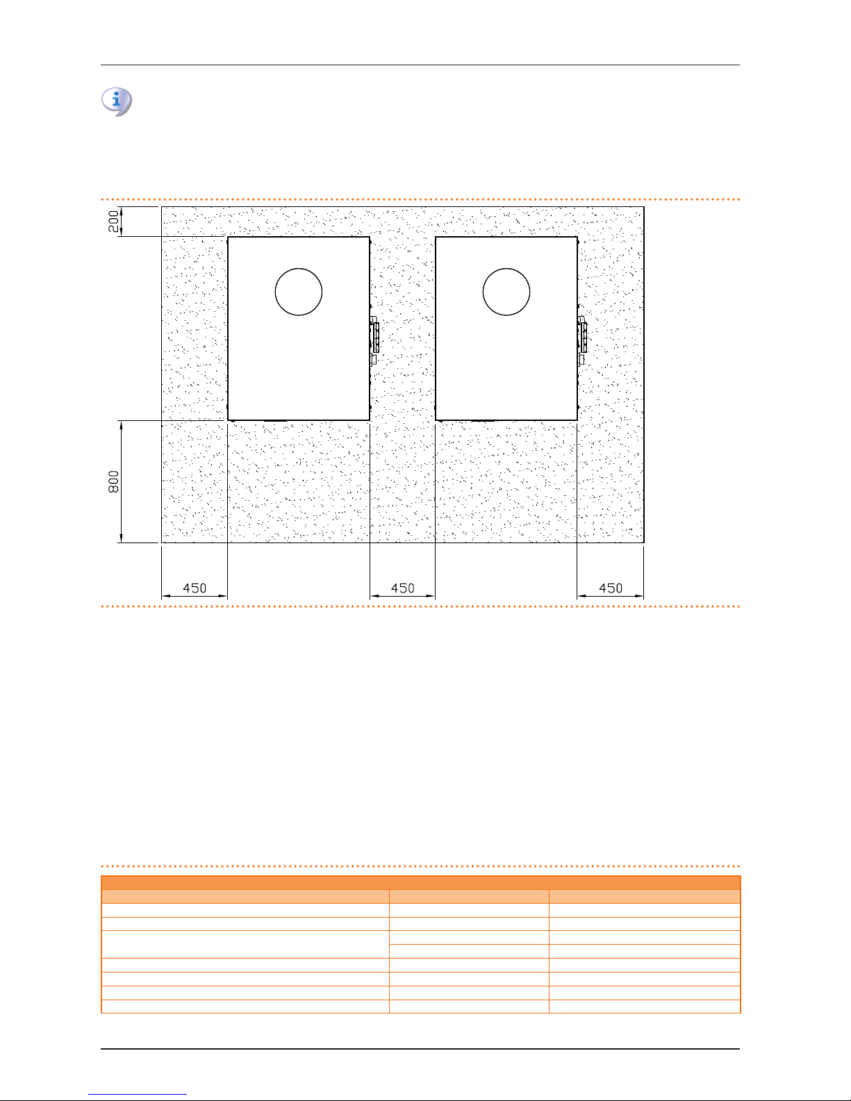
CLEARANCES AND WARNINGS
Position the appliance so as to maintain minimum clearances from combustible surfaces, walls or other appliances, as illustrated
in Figure 5.1→19.
Page 19
5 HYDRAULIC INSTALLATION
Installation, user and maintenance manual – AY Condensing line, AY Series
19
Minimum clearances are required for maintenance accessibility.
The fumes outlet terminals must be installed in such a way that they do not allow the fumes to collect or return to the circuit in the
unit's installation area. The outlet terminal must be constructed in conformity with established regulations.
Position the appliance preferably out of range of rooms and/or environments where strict silence is required, such as bedrooms,
meeting rooms, etc.
Figure 5.1 – Clearances
sample minimum clearances.
LEGEND
* dimensions in mm.
5.3 HYDRAULIC CONNECTIONS
General indications
▶
The hydraulic plant may be created using pipes in stainless steel, black steel, copper or crosslinked polyethylene suitable for
heating and cooling plants. All water pipes and connections must be adequately insulated in accordance with current norms, to
prevent heat dispersion and the formation of condensate.
▶
If glycol antifreeze is to be used (see Paragraph 5.6→25), DO NOT USE galvanised pipes or pipe ttings as they are subject to
potential corrosion phenomena when glycol is present.
▶
If using rigid pipes, use vibration damping couplings at the water and gas connections on the appliance's service plate to prevent
vibration.
As other hydronic appliances, Robur heating and cooling systems operate with grid-water of good quality. In order to prevent any
possible problem of operation or reliability caused by lling or top-up water, please refer to codes and norms about water treatment
for thermo-hydraulic installations in civil or industrial applications. Parameters indicated in Table 5.1→19 must be complied with.
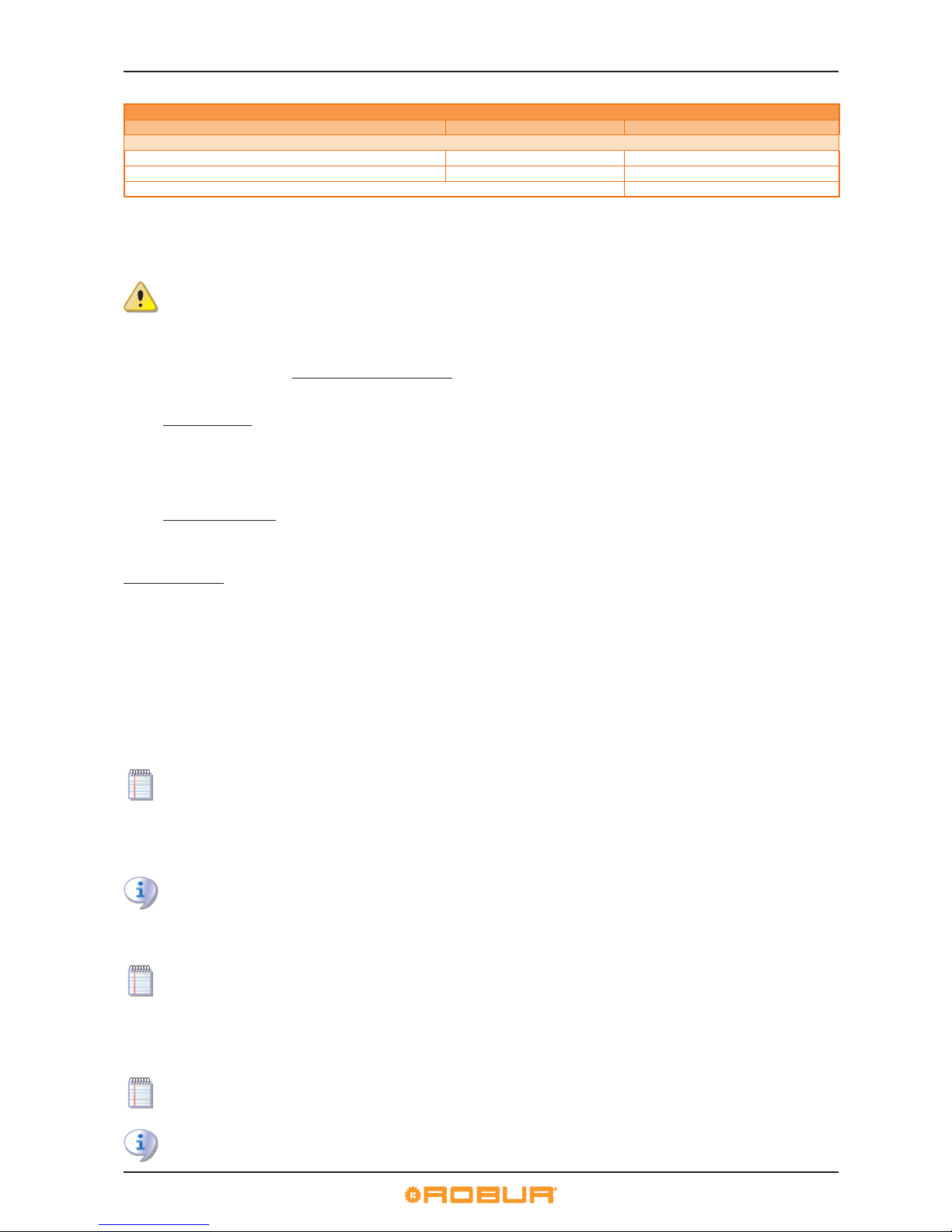
Table 5.1 – Chemical and physical parameters of water
CHEMICAL AND PHYSICAL PARAMETERS OF WATER IN HEATING/COOLING SYSTEMS
PARAMETER UNIT OF MEASUREMENT ALLOWABLE RANGE
pH \ >7
(1)
Chlorides mg/l < 125
(2)
Total hardness (CaCO
3)
°f < 15
°d < 8,4
Iron mg/kg < 0,5
(3)
Copper mg/kg < 0,1
(3)
Aluminium mg/l < 1
Langelier’s index \ 0-0,4
Page 20
5 HYDRAULIC INSTALLATION
20
CHEMICAL AND PHYSICAL PARAMETERS OF WATER IN HEATING/COOLING SYSTEMS
PARAMETER UNIT OF MEASUREMENT ALLOWABLE RANGE
HARMFUL SUBSTANCES
Free chlorine mg/l < 0,2
(3)
Fluorides mg/l < 1
Sulphides ABSENT
1 with aluminium or light alloys radiators, pH must also be lower than 8 (in compliance with applicable rules)
2 value referred to the maximum water temperature of 80 °C
3 in compliance with applicable rules
Water quality can be measured through parameters like acidity, hardness, conductivity, chlorides content, chlorine content, iron
content and the like.
The presence of free chlorine in the water, in particular, can jeopardize parts of the installation and Robur units. Therefore,
please make sure that free chlorine content and total hardness are compliant with the allowable ranges reported in Table
5.1→19.
The way the installation is operated can be the cause of possible degradation of water quality.
Moreover, abnormally massive water top-up or reintegration can cause a drift of chemical or physical above-mentioned parameters.
Reintegration should not exceed 5% per year of the total amount of water. It is advised to check regularly the water quality, especially
in case of automatic or periodic top-up.
In case water treatment is needed, this operation should be carried out by a professional or competent person, following strictly the
instructions by the manufacturer or supplier of the chemical substances for the treatment, since dangers could arise for health, for
the environment and for Robur appliances.
Several products for water treatment are available on the market.
Robur does not perform detailed market surveys. Therefore Robur suggests to contact Companies which are specialized in water
treatments. They will be able to suggest the best way how to proceed according to the type of installation.
In case washing of the pipes is needed, this operation should be carried out by a professional or competent person, following strictly
the instructions by the manufacturer or supplier of the chemical substances for the washing, avoiding the use of substances aggressive for stainless steel or containing/releasing free chlorine.
Please make sure the pipes are properly rinsed in order to remove any residue of chemical substances from the pipes.
Robur is not liable for ensuring that water quality is always compliant with what reported in Table 5.1→19. Non-compliance with
indications above may jeopardize the proper operation, integrity and reliability of Robur appliances, invalidating the warranty.
For any further detail, please contact directly Robur S.p.A. (tel.+39 035.888.111).
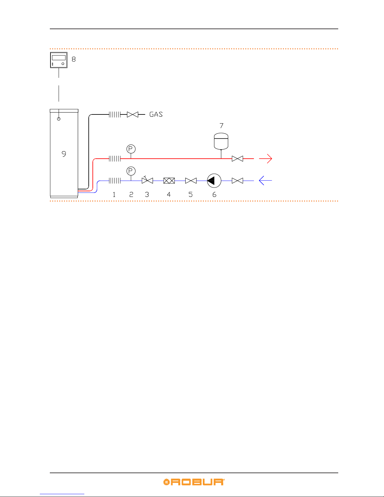
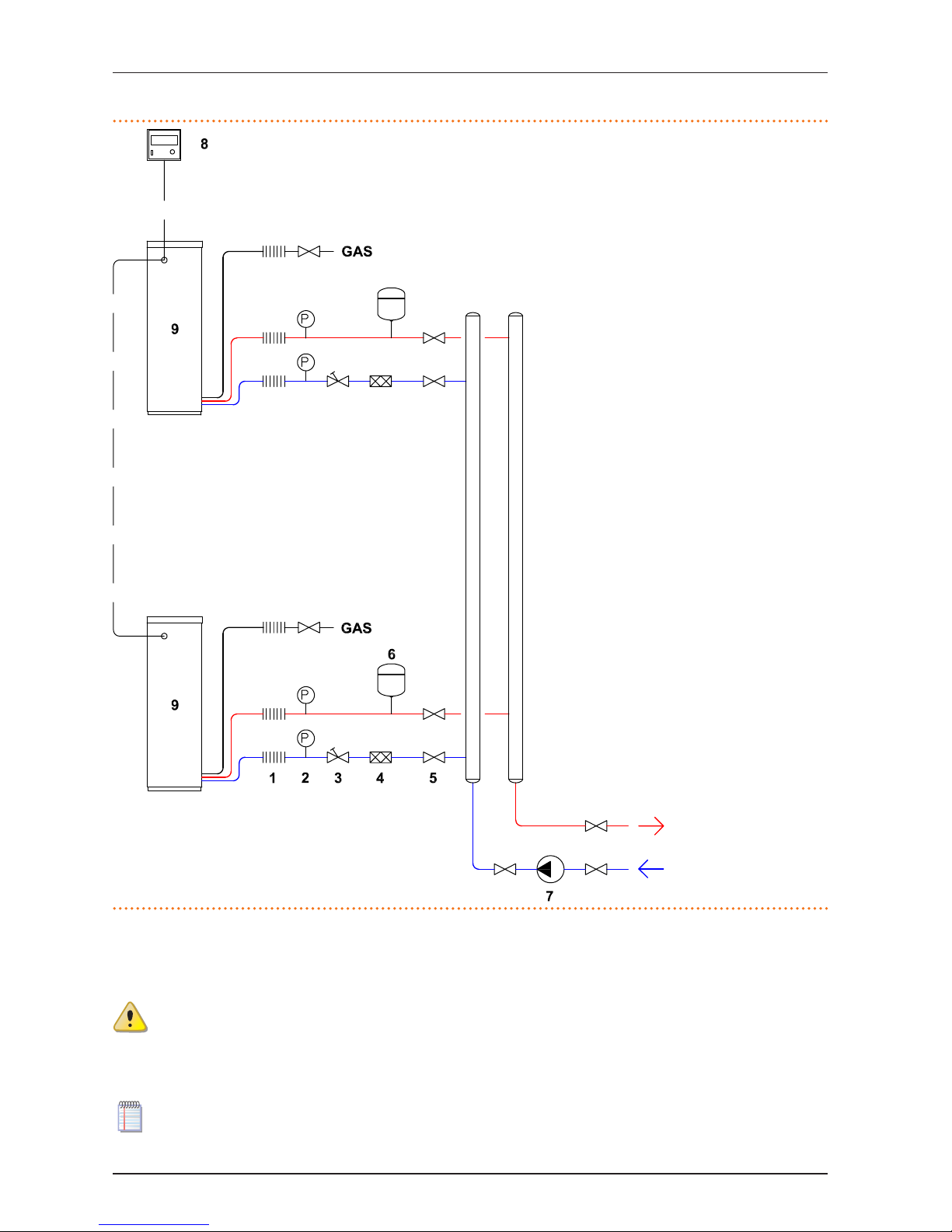
The components described below, to be tted in proximity to the appliance, are illustrated in the typical hydraulic plant schemes in
Figures 5.2→22 and 5.3→23.
▶
VIBRATION DAMPING COUPLINGS
▶
PRESSURE GAUGES (range 0-3 bar).
▶
FLOW REGULATION VALVE (shutter or balancing).
▶
WATER FILTER with mesh MIN 0.7 mm and MAX 1 mm.
▶
BALL CHECK VALVE (also to be tted on the gas supply line).
▶
EXPANSION TANK on system common circuit or each individual appliance:
the appliance is equipped with its own expansion tank on the machine’s internal circuit. the system circuit thus requires a
separate expansion tank, sized in relation to the maximum heat range and the maximum operating pressure of the water in
the plant (see the gures for reference mentioned above).
▶
WATER CIRCULATOR on system common circuit or each individual appliance: chosen to meet the system specications.
▶
INERTIAL TANK (OPTIONAL) or accumulator tank:
By the nature of its operating characteristics, the appliance does not strictly require the installation of an inertial tank on the
hydraulic plant. The use of an inertial tank is, however, recommended in order to compensate for sudden variations in load,
in particular when the plant has a water content of less than 70 litres per appliance.
▶
ACCCUMULATOR BOILER (OPTIONAL) for hot sanitary water (ACS):
The appliance does not itself produce hot water for sanitary (domestic) applications). If it is to be used for this purpose, a
remote accumulator tank must be provided. In this case, any use of glycol in the heating circuit must be FOODSAFE.
▶
Systems for BLEEDING AIR from the pipes.
▶
DRAIN COCK (usually dia. ½”) for system water.
▶
PLANT FILLING SYSTEM:
if automatici lling systems are used, it is advisable to carry out a seasonal check of the percentage of monoethylene glycol
contained in the plant (if present).
Antifreeze
Page 21
5 HYDRAULIC INSTALLATION
Installation, user and maintenance manual – AY Condensing line, AY Series
21
To prevent the water freezing in the internal and system circuits, the appliance is equipped with an antifreeze function.
There are two antifreeze functions, both of which operate only on active modules.
The hydraulic circuit is protected from icing by an electronical anti-freezing function; it operates by activating the water pump (if
directly managed by the unit) ed eventually the burner of the units. The function, already factory activated on every unit, can be
deactivated only by adding an adequate amount of anti-freezing glycole in the hydraulic circuit or by emptying the hydraulic circuit
at the beginning of the winter season.
The second antifreeze function protects the internal circuit against freezing; it runs the internal circuit water circulator. This function
may not be deactivated inasmuch it is also used to protect the machine’s electronics during normal operation.
The machine is factory charged to 2 bar with a water/glycol mix which enables the machine to be safely stored down to
-30°C.
The antifreeze function, in order to protect the internal circuit, actuates the dedicated water circulator so as to keep the
water in the circuit at a temperature of more than -10°C and hence the electrical components at more than -20°C. Make sure
that the machine's internal circuit is always charged with an adequate glycol solution.
It is therefore necessary to ensure a continuous supply of electricity and gas to the appliance throughout the whole of the
winter period. If it is not possible to ensure a continuous supply of electricity and gas to the appliance, use glycol antifreeze
of the inhibited monoethylene type.
Active and passive modules
If the Robur appliances are not controlled by a DDC. In appliances with only hot and only cold modules (e.g.: AY series) or
appliances of the 4 pipe type with two distinct cold and hot modules, the module is ALWAYS "active". in 2 pipe type (hot
and cold) appliances, the “cctive” module is the one that operated the last shutdown; the other module will be the “passive”
module.
If the appliances are controlled by a DDC. If the DDC manages a 2 pipe type plant (only hot, or only cold), or a 4 pipe type
plant (hot and cold), the appliance module is ALWAYS “active”. If the DDC is controlling a 2 pipe hot/cold system, the active
module is the one set as such on the DDC. As an example, if heatingis set on the DDC, all the hot modules managed by the
DDC will be “active”; all the cold modules controlled by the DDC will be “passive”.
If glycol antifreeze is to be used in the hydraulic circuit, DO NOT USE galvanised pipes and connections. Consult the notes on "Possible use of glycol antifreeze" contained in Paragraph 5.6→25 and in any case the technical specications of the glycol to be used.
The sizing of the pipes and pump must guarantee correct operation of the appliance (for calculation of pressure drops in the appliance, refer to the technical data, Paragraph 3.4→9).
The operations necessary for the rst activation or regulation of the appliance and of the Direct Digital Controller must be
carried out exclusively by an authorized Robur Technical Assistance Centre (TAC). These operations are described in Section
7→50.
The products’ guarantee is void if initial activation is not carried out by a Robur TAC.
The following gures show examples of typical hydraulic circuits, composed of a single or multiple appliances.
For further information and technical support regarding other congurations, contact Robur S.p.A. Presales. (tel. 035
888.111).
Page 22
5 HYDRAULIC INSTALLATION
22
Figure 5.2 – Diagram of hydraulic system (type with single appliance)
Example of hydraulic plant diagram for connection of no. 1 AY00-120 unit.
LEGEND
1 anti-vibration coupling
2 pressure gauge
3 ow regulator valve
4 water lter
5 check valve
6 system water circulator
7 system expansion tank
8 DDC
9 AY00-120 stand-alone
Page 23
5 HYDRAULIC INSTALLATION
Installation, user and maintenance manual – AY Condensing line, AY Series
23
Figure 5.3 – Diagram of hydraulic system (type with several appliances)
Example of hydraulic plant diagram for connection of no. 2 AY00-120 units.
LEGEND
1 anti-vibration coupling
2 pressure gauge
3 ow regulator valve
4 water lter
5 check valve
6 system expansion tank
7 system water circulator
8 DDC
9 AY00-120 stand-alone
5.4 GAS SUPPLY
The installation of gas supply pipes must be compliant with current regulations and norms.
For the pressure of the gas supplied by the mains see Table 5.2→24.
Supplying gas to the appliance at pressures higher than those indicated above can damage the gas valve, resulting in dangerous situations.
LPG systems must be equipped with a rst stage pressure reducer close to the LPG storage tank, in order to reduce the gas pressure
to 1,5 bar, and a second stage pressure reducer, close to the unit, in order to reduce pression from 1,5 bar to the value in agreement
with the gas network pressure of the country of installation (see Table 5.2→24).
Exemple for the Italian market: for the G30 gas, from 1,5 bar to 0,030 bar (30mbar); for the G31 gas, from 1,5 bar to 0,037 bar
(37mbar).
Page 24
5 HYDRAULIC INSTALLATION
24
LPG may cause corrosion; piping and tting materials must be resistant to this corrosion.
Vertical gas pipes must be equipped with a siphon and provided with a drain for the condensate that may form inside the pipe during cold periods. It may also be necessary to insulate the gas pipe to prevent the formation of excessive condensate.
In any case, provide an isolation valve (ball valve) on the gas supply line, to isolate the appliance when required.
Table 5.2 – Network gas pressure
AY00-120; E3 AY00-120 Gas supply pressure
Product categories Countries of destination G20 [mbar] G25 [mbar] G30 [mbar] G31 [mbar]
G25.1
[mbar]
G27 [mbar] G2,350 [mbar]
II
2H3B/P
AL, BG, CZ, DK, EE, FI, GR, LT,
NO, SE, SI, SK, TR
20 30 30
AT, CH 20 50 50
HR, MK, RO 25 30 30
IT 20 28-30 37
II
2H3P
AL, BG, CZ, ES, GB, IE, LT, PT,
SI, SK
20 37
HR, MK, RO 25 37 37
II
2HS3B/P
HU 25 30 30 25
II
2E3P
LU 20 50
II
2ELL3B/P
DE 20 20 50 50
II
2Esi3P *
FR 20 25 37
II
2L3B/P
NL 25 50 50
II
2E3B/P
PL
20 37 37
II
2ELwLs3B/P
20 37 37 20 13
II
2ELwLs3P
20 37 20 13
I
2E(S); I3P
BE 20 25 37
I
2H
LV 20
I
3B
MT 30
I
3B/P
CY, MT 30 30
I
3P
IS 30
Note: values reported in table are the nominal one, it is in any case accepted a value within the tollerance range of ±15% (Pmin/Pmax).
For data regarding hourly fuel consumption of the appliance, refer to Table 3.1→9.
5.5 CONDENSATE DISCHARGE
The fumes exhaust pipe is located on the right of the appliance on the service plate.
To install/connect the condensate discharge pipe, proceed as follows:
The condensate discharge to the sewer must be:
▶
made of materials resistant to acidity with pH 3 to 5;
▶
sized to ensure a slope of 10 mm per metre of length; if this slope cannot be achieved, a condensate pump (available as an accessory) must be installed near to the discharge - see Section 8→58);
▶
realized in such a way as to prevent icing of the condensate;
▶
mixed, for example, with domestic euent (washing machine, dishwasher, etc.), usually of base pH, so as to form a buer solution
before discharge into the sewer.
Do not discharge the condensate into the gutter drains, given the risk of icing and degradation of the materials usually used
for such drains.
CHARGING THE SIPHON
In case of residential installation, to prevent an initial discharge of combustion products from the condensate drain, charge the
siphon itself as follows:
1. remove the appliance's front panel and open the interior panel to access the siphon;
2. if the fumes exhaust equipment has not yet been installed, pour 0.2 litres of water directly into the plastic fumes exhaust pipe
accessible from the top panel (see Figure 5.6→28 - detail "D") and visually check that the siphon is full, then go to step 5.
Otherwise, proceed as follows;
3. remove the clamp, disconnect the plastic siphon pipe and ll it with 0.2 litres of water;
4. reconnect the plastic pipe and secure it with its clamp;
5. restore the appliance.
If the appliance is operated with the siphon empty, there is a risk of leaks of combusted gas.
Page 25
5 HYDRAULIC INSTALLATION
Installation, user and maintenance manual – AY Condensing line, AY Series
25
5.6 FILLING THE SYSTEM CIRCUIT APPLIANCE
After having completed all hydraulic, gas and electrical connections, the installer can proceed lling the hydraulic circuit, observing
the following steps:
▶
Activate the automatic air vent valves on the system circuit.
▶
Fill the hydraulic circuit, ensuring the minimum water content in the plant, and adding, if necessary, to the plant water (free of
impurities) a quantity of monoethylene glycol in proportion with the minimum winter temperature in the installation zone (see
table 5.3→25).
▶
Bring the plant to the correct pressure, making sure that the pressure of the water in the plant is not less than 1 bar and not over
2 bar.
Possible use of glycol antifreeze
Glycols, normally used to lower the freezing point of water, are substances in an intermediate state of oxidisation which, in the presence of oxidising agents such as oxygen, are transformed into corresponding acids.
This transformation into acids increases the corrosive nature of the uid contained in the circuit. For this reason, mixtures that are
commercially available almost always contain inhibiting substances that are able to control the pH of the solution.
A necessary condition for the oxidisation of the glycol, and therefore its degradation, is the presence of an oxidising agent such as
oxygen.
In closed circuits in which no replenishment of water, and therefore of oxygen, occurs over the course of time, once the oxygen initially present has reacted, the degenerative phenomenon of glycol is hugely inhibited.
Most circuits, however, are of the non-sealed type, and therefore receive a more or less continuous supply of oxygen.
Therefore it is essential, whatever type of glycol is in question, to verify that it is adequately inhibited and that the necessary checks
are regularly performed during its entire period of use.
Antifreeze liquids for cars, which do not contain inhibiting components, are not recommended for cooling and heating
plants. The manufacturer does not accept any contractual or extra-contractual liability for damage caused by the use
or incorrect disposal of glycol antifreeze.
It is equally important to recall that the use of monoethylene glycol modies the thermophysical characteristics of the water in the
plant, and in particular its density, viscosity and average specic heat. Always check the date of expiry and/or degradation of the
product with the supplier.
Table 5.3→25gives the approximate freezing temperature of the water and consequent increased drop in pressure of the appliance
and of the circuit of the plant, according to the percentage of monoethylene glycol. This table should be borne in mind when sizing
the pipes and water circulator: for pressure drop calculations, see the data in paragraph 3.4→9).
Nevertheless, it is advisable to consult the technical specications of the monoethylene glycol used. If automatic loading systems are
used, a seasonal check of the quantity of glycol present in the plant is also necessary.
Table 5.3 – Technical data for lling the hydraulic circuit
% of MONOETHYLENE GLYCOL 10 15 20 25 30 35 40
WATER-GLYCOL MIXTURE FREEZING
TEMPERATURE
-3°C -5°C -8°C -12°C -15°C -20°C -25°C
PERCENTAGE OF INCREASE IN PRESSURE DROPS -- 6% 8% 10% 12% 14% 16%
5.7 FILLING THE APPLIANCE’S INTERNAL CIRCUIT
The machine is factory charged to 2 bar with a water/glycol mix which enables the machine to be safely stored down to
-30°C.
The antifreeze function, in order to protect the internal circuit, actuates the dedicated water circulator so as to keep the
water in the circuit at a temperature of more than -10°C and hence the electrical components at more than -20°C. Make sure
that the machine's internal circuit is always charged with an adequate glycol solution.
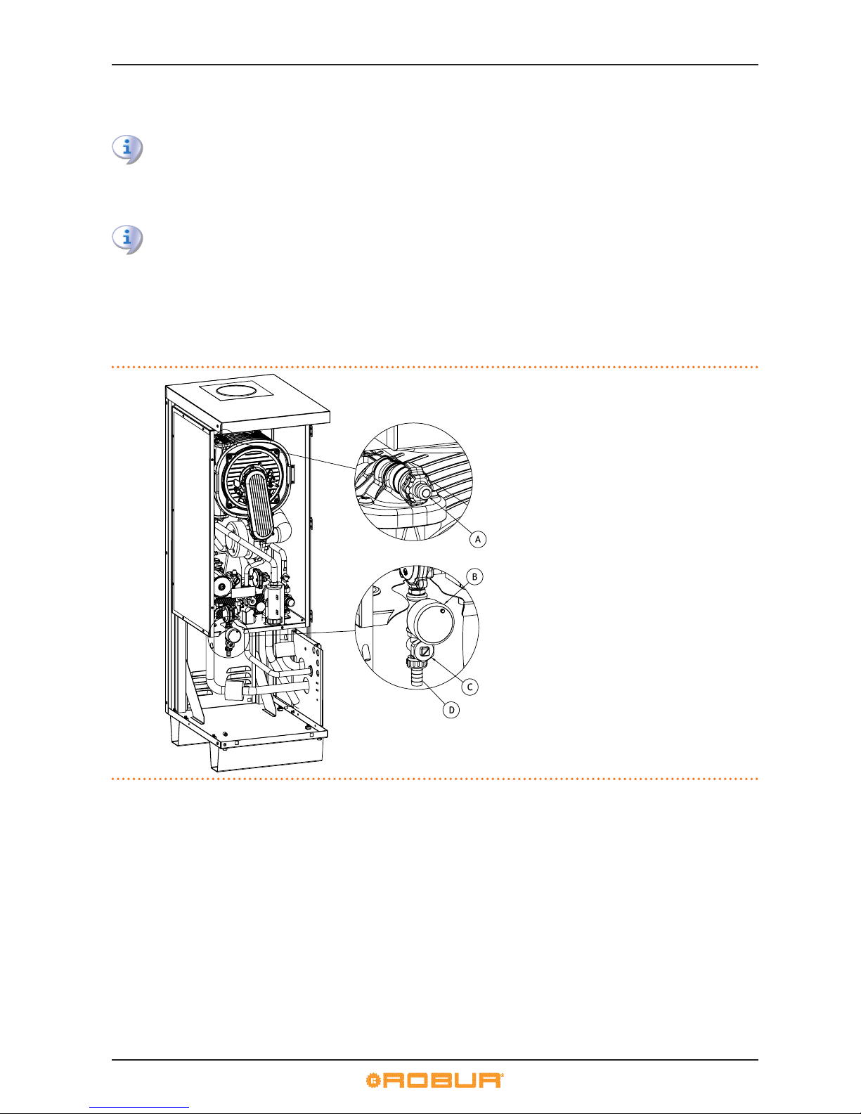
Remove the front panel of the appliance to read the internal circuit charging pressure of the appliance on the external lling pressure
gauge (Figure 5.4→26, detail B).
The optimal pressure value is in the range 1 and 2 bar. If the internal circuit must be recharged, proceed as follows:
The internal circuit is hermetically sealed. If the circuit is empty (this is a fault), identify the leak and restore the seal (for example, by replacing defective gaskets) before proceeding.
You will need: 50-50 glycol solution; volumetric charging pump capable of pressuring the circuit to 2 bar; hose to connect
to the provided D.13 union; provided union.
1. Remove the front panel.
2. Open the internal front panel.
3. Remove the cap closing the ller cap and connect the provided D.13 union (Figure 5.4→26, detail D).
Page 26
5 HYDRAULIC INSTALLATION
26
4. Connect the volumetric charging pump to the union with a hose.
5. Open the ller cock (Figure 5.4→26, detail C), with a athead screwdriver, and charge the circuit with enough glycol solution
to achieve the specied optimal pressure.
Take care not to allow air to enter the circuit.
1. Open the cap on the automatic bleed valve on the internal circuit and run the machine for 3 minutes to bleed the circuit.
2. If the circuit gurgles during operation, this indicates that air is present in the circuit; connect a hose to the manual bleed cock
on the top of the combustion unit (Figure 5.4→26, detail A), open the cock by turning it counterclockwise and bleed the circuit. Once the circuit has stopped gurgling, close the cock and remove the hose.
During manual bleeding, any liquid which has been bled out of the circuit must be replaced with the charging pump. Make
sure that the circuit pressure is 1-2 bar on completion of the following procedure.
1. Stop the circuit operating, close the charging cock with a athead screwdriver and close the automatic bleed valve on the
circuit.
2. Disconnect the volumetric pump, remove the union and replace the ller cap.
3. Close the front panel with its retainer bolts.
4. Restore the appliance and put away the union.
Figure 5.4 – Filling the machine's internal circuit
Detailed description of lling procedure.
LEGEND
A manual air vent cock
B pressure gauge
C ller cock *
D hose tting D.13 standard supply
* notch in horizontal position: cock closed;
notch in vertical position: cock open.
5.8 EXHAUST FLUE GAS
The appliance, which is supplied in the B53P conguration for installation in the open, is equipped as standard supply with a DN80
fumes kit (nominal diameter 80 mm).
The supplied fumes kit must be installed by the installation technician.
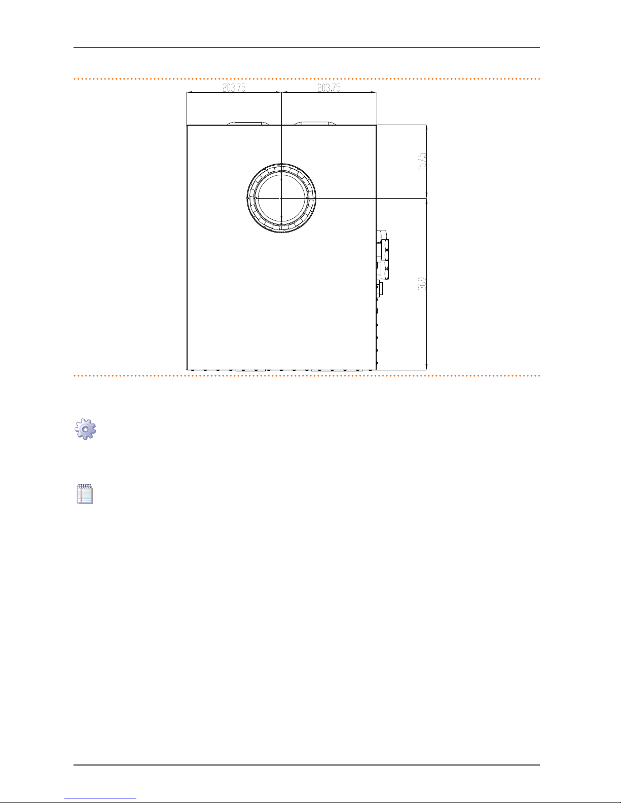
The DN80 union for connecting the fumes kit to the appliance is located at the top of the latter (see Figure 5.5→27) with a vertical
outlet.
Page 27
5 HYDRAULIC INSTALLATION
Installation, user and maintenance manual – AY Condensing line, AY Series
27
Figure 5.5 – AY Condensing line, AY series
Fumes outlet tting (dimensions in mm) - seen from above.
FUMES EXHAUST EQUIPMENT FOR EXTERNAL INSTALLATION (installation technician only)
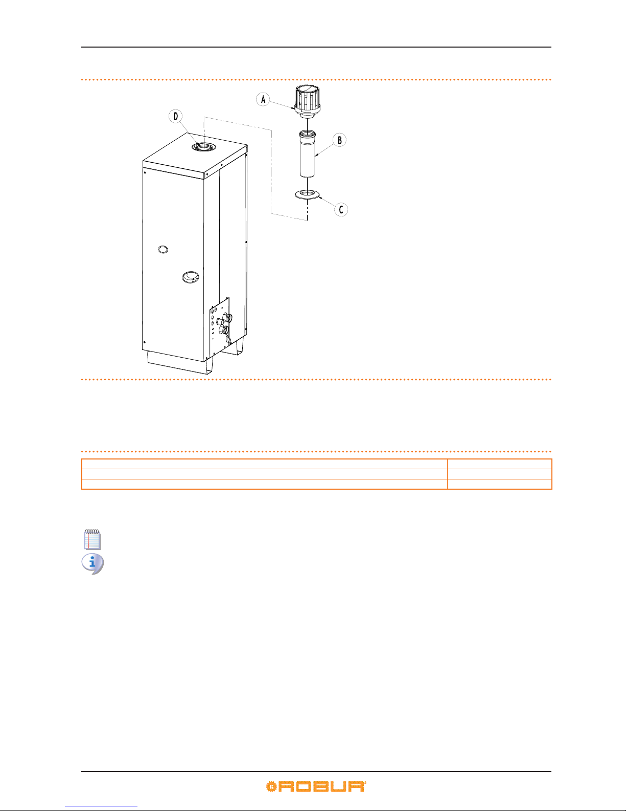
Install the equipment externally as follows (see Figure 5.6→28).
You will need: the appliance in its permanent location. Necessary equipment and materials.
1. Fit the DN80 roof terminal (detail A) inside the cone on the end of the DN80 extension pipe (detail B).
2. Fit the DN80 rain guard (detail C) to the DN80 extension pipe (B), with the rain guard lip turned towards the exterior of the kit
(A+B+C).
3. Remove the protective cap on the top panel.
The cap prevents water and foreign bodies entering the appliance before the fumes kit is installed. The cap should thus be
removed only when the kit itself has been fully assembled and installed.
4. Fit the DN80 extension pipe (assembly A+B+C) into the cone of the DN80 anged union which can be accessed via the appliance’s top panel (detail D). Take care to position the rain guard properly so that it prevents foreign bodies entering the hole in
the top panel.
Page 28
5 HYDRAULIC INSTALLATION
28
Figure 5.6 – Fumes evacuation pipe kit
fumes kit for exterior conguration (B53P).
LEGEND
A roof mounting terminal (DN80)
B extension tube (DN80)
C rain cover (DN80)
D anged tting (DN80) on top panel
A+B+C fumes evacuation pipe kit
SIZING FUMES PIPES FOR TYPE B INSTALLATIONS
If the installation requires the combustion products to be conveyed in a type B conguration, the ue must be sized with reference
to the following table.
Table 5.4 – Fumes evacuation pipe ducting (type B)
Useful residual head 100 Pa
Maximum length of straight DN80 pipe sections 31.0 m
Equivalent DN80 curve length at 90° 2.0 m
Data for sizing type B installation ues.
Example: to install a horizontal fumes pipe using n. 1 DN80 90° curve, the maximum extension possible with DN80 straight pipe
sections is 29 m.
The following other type B congurations are also possible: B23P and B33 (for specications, see Table 5.6→29).
Exhaust pipes exposed to atmospheric agents must be made of black polypropylene or an equivalent weather resistant
material. For sizing, refer to the established regulations and the manufacturer’s instructions.
SIZING AIR/FUMES PIPES FOR TYPE C INSTALLATIONS
The appliance is homologated for conguration as a type C installation. The following congurations are permitted: C13, C33, C43,
C53, C63 and C83 (for specications, see Table 5.6→29).
To install the appliance in a type C conguration refer to the following technical data table for the sizing of the combustion fumes
outlet and combustion air intake pipes.
Page 29
5 HYDRAULIC INSTALLATION
Installation, user and maintenance manual – AY Condensing line, AY Series
29
Table 5.5 – Ducting for fumes evacuation and air intake pipes (type C)
Gas type G20 G25 G25.1 G27 G2.350 G30 LPG G31
Useful residual head Pa 120
Mass of fumes at nominal thermal capacity
kg/h
55.0 62,0 49.0 55.0 56.0 49.0 49.0 56.0
Mass of fumes at minimal thermal capacity 13.0 15.0 12.0 13.0 13.0 12.0 12.0 13.0
Temperature of fumes at nominal thermal capacity
°C
72.5 72,0 72,0 72,0 72,0 71.5 71.5 72.5
Temperature of fumes at minimal thermal capacity 71.6 72,0 71,0 71.5 72,0 71.5 71.5 71.5
CO
2 content at nominal thermal capacity
%
9.4 9.4 10,7 9,35 9,15 12,4 11.4 10.6
CO
2 content at minimal thermal capacity
8.9 8.9 10.2 8,90 8,80 11,5 10,5 10.2
Data for sizing type C air/fumes installation pipes.
Examples of the two principal type C congurations:
▶
C13 - using a concentric DN60/100 90°C curve, the maximum permitted extension with concentric DN60/100 straight pipe sections is 5.75 m, while the minimum permitted extensions is 0.75 m.
▶
C33 - the maximum permitted extension with concentric DN60/100 straight pipe sections is 6.25 m.
Exhaust pipes exposed to atmospheric agents must be made of black polypropylene or an equivalent weather resistant
material. For sizing, refer to the established regulations and the manufacturer’s instructions.
The following table gives a brief description of the possible installation congurations.
Table 5.6 – Installation conguration (types B and C)
TYPE CONFIGURATION
B23P
The combustion products are exhausted outside, from the wall or roof, while the combustion air is drawn directly from the room in which the appliance is
installed. This conguration can ONLY be installed in open areas or areas suciently well ventilated and free of combustible powders.
B33
Evacuation of combusted gas into the ue, combustion air drawn directly from the room in which the appliance is installed. This conguration can ONLY be
installed in open areas or areas suciently well ventilated and free of combustible powders.
B53P
Boiler designed for connection, via its own pipe, to a dedicated combustion product evacuation terminal. The air is drawn from the installation room and the
combustion products are evacuated outside the room. This conguration can ONLY be installed in open areas or areas suciently well ventilated and free of
combustible powders.
C13
Type C boiler connected, via its own pipes, to a terminal installed horizontally on the wall or roof. The outlets of the pipes are concentric or suciently close to
each other to be exposed to analogous wind conditions.
C33
Type C boiler connected, with its pipes, to a vertical terminal. The outlets of the pipes are concentric or suciently close to each other to be exposed to
analogous wind conditions.
C43
Type C boiler connected, via its pipes and optionally with a tting, to a collective piping system composed of a pipe for combustion air supply and a pipe for
combustion product evacuation. The outlets of the system of collective pipes are concentric or suciently close to each other to be exposed to analogous
wind conditions.
C53 Type C boiler connected, via its separate pipes, to two terminals which can be installed in zones at dierent pressures.
C63 Type C boiler designed for connection to a system for combustion air supply and combustion product evacuation which is approved and sold separately.
C83 Type C boiler connected, via its pipes, and optionally via a tting, to an air supply terminal and connected to a dedicated or collective ue.
Description of possible appliance installation congurations.
5.9 PROGRAMMING OF HYDRAULIC PARAMETERS
The hydraulic parameters can be set according to the procedure described in this paragraph only when the appliance is not
connected to a DDC.
If the appliance is connected to a DDC, follow the instructions given in the DDC manuals exclusively.
To congure the hydraulic parameters, access menu 3 of the controller.
For the use of the controller, refer to procedure "HOW TO ACCESS THE MENUS" in Paragraph 4.2→14.
Table 5.7→29 gives the three parameters used for hydraulic conguration.
Table 5.7 – Menu 3 parameters
HYDRAULIC PARAMETER THE DISPLAY SHOWS
Hot water thermostat control selection 3.160
Hot water setpoint 3.161
Hot water temperature dierential 3.162
(EXIT MENU) 3. E
Description of parameters
▶
Hot water thermostat control: parameter "160". This parameter takes two values: "0" and "1". Value "0" indicates that the appli-
ance's "activation/deactivation" temperature is to be read by the water probe at the appliance’s INTAKE. Value "1" indicates that
the appliance’s "activation/deactivation" temperature is to be read by the water probe at the appliance’s OUTLET.
Page 30

5 HYDRAULIC INSTALLATION
30
▶
Hot water setpoint: parameter "161". this parameter sets the water temperature that, when reached, causes the appliance to be
deactivated.
▶
Hot water dierential: parameter "162". This parameter represents an interval in degrees that, when added to the set-point, de-
nes the temperature at which the appliance is reactivated.
Heating mode:
The appliance heats the water until it reaches the setpoint temperature. The appliance then switches o. This means that the water
temperature slowly drops to the setpoint + dierential temperature. At this point, the appliance turns back on.
For example, if we set the following values:
▶
Thermostat control: "0" (= read INTAKE water temperature).
▶
Setpoint: +40.0 °C.
▶
Dierential: -2.0 °C.
The appliance will behave as follows:
1. the water temperature rises (heating);
2. the intake water temperature reaches +40 °C (= setpoint);
3. The appliance switches o;
4. the system water temperature slowly drops (loses heat to the environment);
5. the intake water temperature reaches +38 °C (= setpoint + dierential);
6. the appliance turns back on: heating starts again. The cycle is repeated.
The following instructions give a detailed description of how to congure the hydraulic parameters in menu 3 (or menu 4) on the
machine’s controller.
Hydraulic parameter settings
You will need: the controller’s display sequentially shows the operating data (temperature, delta T°) regarding the current
mode (e.g.: heating). Special key provided with the appliance.
1. See procedure "HOW TO ACCESS THE MENUS" (Paragraph 4.2→14) and proceed as described in steps "1" to "5".
2. The display will now ash "0.". Turn the knob until menu 3 displays (the display shows "3.") or menu 4 (the displays shows "4.").
▶
For example: to set the parameters of menu 3:
1. The display shows “3.”. Press the knob to access the menu. the display shows the rst of the menu parameters: "3.73" or "3.160"
(= menu 3, parameter "73" or "160").
2. The display shows "3.73" or "3.160". To access a parameter, press the knob: the displays shows the preset value (e.g. "1"), ashing, to indicate that it can be modied.
3. Press again to conrm "1" (= outlet water thermostat control); to modify the value, turn the knob until "0" displays: press to
conrm "0" (= intake water thermostat control).
4. The display now shows the current parameter "3.73" or "3.160" again: the parameter has been set to its new value.
5. Turn the knob to display the next parameter. The display shows: "3.75" or "3.161". To access a parameter, press the knob: the
displays shows the preset value (e.g. "60"), ashing, to indicate that it can be modied.
6. Press again to conrm "60" (= water temperature setpoint); to modify the value, turn the knob until the desired value displays
(e.g. "40"): press again to conrm "40" (= water temperature setpoint);
7. The display now shows the current parameter "3.75" or "3.161" again: the parameter has been set to its new value.
8. Turn the knob to display the next parameter. The display shows: "3.76" or "3.162". To access a parameter, press the knob: the
displays shows the preset value (e.g. “-10"), ashing, to indicate that it can be modied.
9. Press again to conrm “-10" (= water temperature dierential); to modify the value, turn the knob until the desired value displays (e.g. “-2"): Press again to conrm “-2" (= water temperature dierential).
10. The display now shows the current parameter "3.76" or "3.162" again: the parameter has been set to its new value.
11. To quit menu 3, turn the knob clockwise until the quit screen displays: "E". The display shows “3.”. E": press the knob. The display
will now show the current menu "3.". To exit the menu selection screen, turn the knob clockwise until “E” displays: press to
conrm.
The controller’s display now sequentially shows, as at the beginning, the operating data (temperature, delta T) regarding the
current mode (e.g.: heating).
To modify a parameter in menu 4, to access the menu (installation technician only) you are rst prompted for a password. For
the password, contact the Robur TAC or Technical Service Department of Robur S.p.A. (Tel. +39.035.888111).
The special key allows the knob of the electronic board to be operated without opening the cover of the electrical panel, so
that operators are protected from live components. When the necessary settings have been completed, put away the special
key, replace the cap on the aperture of the electrical panel and ret the front panel of the appliance.
SPECIAL PARAMETER SETTINGS
The appliance is a Range Rated boiler: the power delivery of the appliance can be adapted to the real system requirements by regulating the nominal gas ow (nominal thermal input).
The thermal input can be regulated with parameter "180" in menus 4 and 5. The parameter has a range from maximum (34.9 kW) to
minimum (8.0 kW) thermal capacity (see also Table 3.1→9).
Page 31

5 HYDRAULIC INSTALLATION
Installation, user and maintenance manual – AY Condensing line, AY Series
31
If multiple appliances are connected to the system, the value of parameter "180" must be the same for all appliances.
To prevent errors in setting the hydraulic parameters available to the user in menu 3, we recommend setting the maximum water
temperature setpoint, both at the outlet (parameter "156") and the intake (parameter "157"), accessible in menu 5 (and hence for the
Robur TAC only). For example, if the appliance is used on a system for underoor heating, parameters "156" and "157" must be set
to limit the user's options in setting temperature setpoint parameter "161" (also available in menu 3) and thus prevent operational
settings outside the installation design limits.
The appliance’s internal circuit is factory charged, ad hoc, with a monoethylene glycol solution sucient to enable storage down to
-30°C. Any topping up of the initial charge must restore the optimal water/glycol mix (50/50).
However, parameter "180" allows the appliance to be congured for operation with pure water or a non-optimal glycol solution
(value “0”: no glycol in the machine’s internal circuit); in this case the antifreeze function will activate the internal water circulator to
keep the water temperature above +4°C. Within the limits of the design minimum ambient temperature it may be necessary, in such
cases, to ensure continuous electrical power to the appliance even during periods of disuse.
Parameter "156" is to be used ONLY by the Robur TAC; parameters "180" and "182" are also available to the installation technician. These special parameters may be congured, when so required, only by the Robur TAC or the installation technician,
when authorised to do so.
Page 32
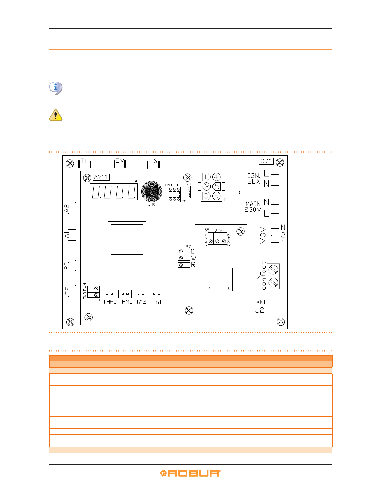
6 ELECTRICAL INSTALLATION
32
6 ELECTRICAL INSTALLATION
In this section you will nd all the instructions necessary to connect electrically the appliance.
The procedures to follow in order to complete the entire process of electrical installation of the appliance are the following:
1. CONNECTING THE APPLIANCE TO THE MAINS.
2. ELECTRICAL CONNECTIONS FOR THE SYSTEM CIRCULATOR.
3. CONNECTIONS FOR CONSENT SWITCH OPERATION.
Before proceeding with operations to create the electrical plant of the appliance, the professionally qualied personnel concerned are advised to read Paragraph 3.1→7: it provides important information regarding installation safety and references
to current regulations.
Before making the electrical connections or any checks, make sure that work is not carried out on live elements.
Figure 6.1→32 illustrates, in their main parts, the on-board electronics: controller AY10 overlaying the auxiliary controller S70 (for the
legend, see Table 6.1→32).
Figure 6.2→34 detail plant of the appliance.
Figure 6.1 – Series AY - AY10+S70 controllers
Main components of the on-board controller.
LEGEND
see table below
Table 6.1 – AY10 and S70 controller components
CONTROLLER COMPONENT LEGEND
CODE DESCRIPTION
COMPONENTS OF CONTROLLER S70
TL limit thermostat connector
EV gas solenoid valve connector
LS gas valve ON indicator lamp connector
P1 ame controller connector
TF fumes thermostat connector
PD circuit water dierential pressure switch connector
A1 - A2 auxiliary connectors
J2 circuit water circulator controller jumper
No Contact system water circulator controller terminal clamps (max 700W)
V3V (1-2-N) machine circulator terminal clamps
MAIN 230V (L-N) power supply connector
IGN. BOX (N-L) ignition controller connector
COMPONENTS OF CONTROLLER AY10
Page 33
6 ELECTRICAL INSTALLATION
Installation, user and maintenance manual – AY Condensing line, AY Series
33
CONTROLLER COMPONENT LEGEND
CODE DESCRIPTION
P1
blower control connector
PWM= signal output GND= ground
THRC input hot water temperature probe connector
THMC output hot water temperature probe connector
TA2-TA1 auxiliary temperature probes connector
J1 CAN BUS jumper
P8 [GND-L-H]
CAN port / connector
H= high data signal L= low data signal GND= common data signal
P7 (R-W-0)
operation consent connector
R= common terminal W= HOT consent terminal 0= terminal not used
FS5 [24ac1-0V-24ac2] controller power connector
F1 - F2 fuses
Controller component legend.
Page 34
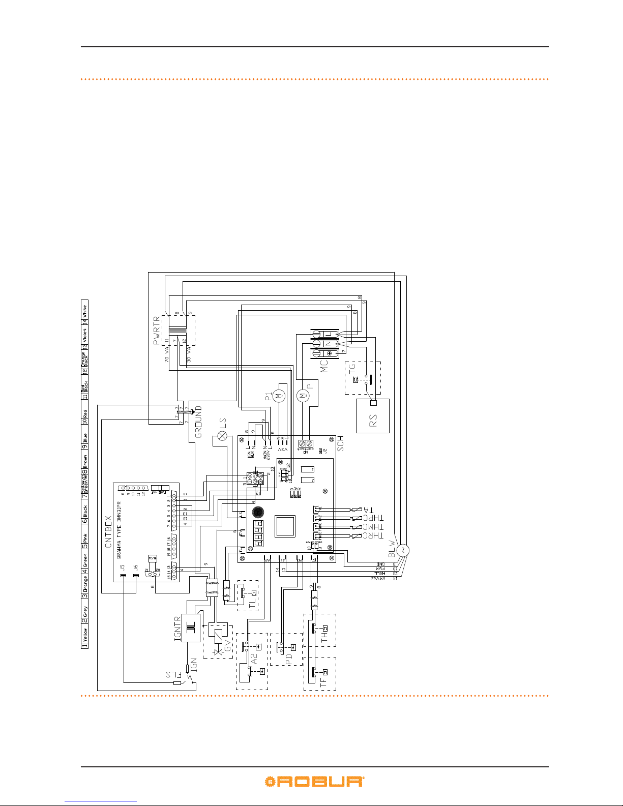
6 ELECTRICAL INSTALLATION
34
Figure 6.2 – Functional diagram
Electric diagram single unit AY00-120.
LEGEND
SCH controllers (AY10/S70)
TA ambient temperature probe
THPC delivery water temperature probe
(appliance internal circuit)
THMC outlet water temperature probe
(system circuit)
THRC inlet water temperature probe
(system circuit)
TH combustion unit limit thermostat
(appliance internal circuit)
TF exausted gas thermostat
A2 dierential water pressure switch
(appliance internal circuit)
PD dierential water pressure switch
(system circuit)
TL water limit thermostat
P1 water circulator
(appliance internal circuit)
LS gas valve ON indicator lamp
GV gas solenoid valve
IGNTR ignition transformer
IGN ignition electrodes
FLS ame sensor
CNTBOX ame controller
BLW blower
MC power terminal block 230Vac
PWRTR controller transformer
TG antifreezing thermostat for siphon heating element
RS siphon heating element
P * water circulator (system circuit)
* only for LINK's unit in "CC" conguration
(n.1 circulator for single module)
6.1 CONNECTING THE APPLIANCE TO THE MAINS
The examples of connection of the appliance to the mains in this paragraph refer to:
▶
single appliance plants
Page 35
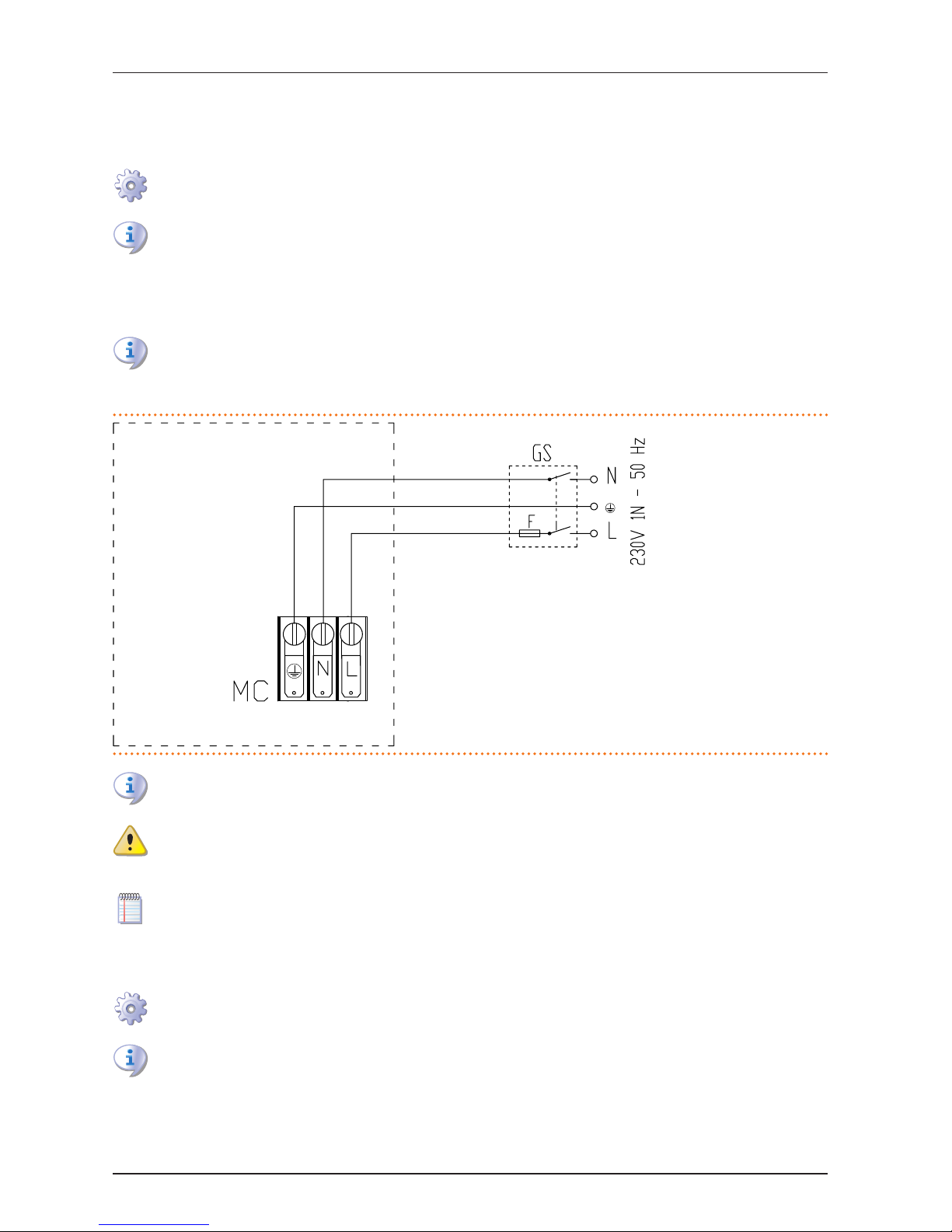
6 ELECTRICAL INSTALLATION
Installation, user and maintenance manual – AY Condensing line, AY Series
35
▶
multiple appliance plants
SINGLE APPLIANCE PLANTS
The appliance must be connected to a 230 V 1N - 50 Hz power supply, as follows (see example in Figure 6.3→35):
You will need: the appliance connected hydraulically; external electrical panel congured by the installation technician.
Necessary equipment and materials.
Make sure that the electrical panel congured by the technician is equipped with a 2 pole circuit breaker with minimum air
gap of 3 mm, and a 2A type T fuses.
1. Remove the appliance's front panel and open the electrical panel by removing the bolts securing it.
2. Prepare a cable of the FG7(O)R 3Gx1.5 type for the power supply to the appliance.
3. Locate terminal block "MC" inside the panel and hook up as shown in the gure.
4. On completion, restore the appliance to its fully assembled condition.
The insertion of relays or other electrical components inside the General Electrical Panel of the appliance is not permitted.
Do not activate the appliance if the hydraulic plant has not been lled.
Figure 6.3 – connection to electrical mains (230 V 1N - 50 Hz)
Example of connection of no. 1 appliance to the mains.
LEGEND
MC power terminal block
GS Master 2-pole power switch
F Fuse/s
N Neutral terminal
Ground ground terminal
L single-phase line terminal
Disconnect the appliance from the electrical power supply via the external disconnecting switch only after having performed the shutdown cycle (via the DDC or consent switch) and having waited for it to terminate (approximately 3 minutes).
Make sure the ground cable is longer than the live cables. In this way it will be the last wire to be pulled away if the mains
cable should accidentally be pulled, and will thus guarantee the ground connection. Do not use gas pipes to ground
electrical appliances.
A wiring error, as well as impeding the correct operation of the appliance, could also damage the electrical apparatus that
it contains.
MULTIPLE APPLIANCE PLANTS
The appliance must be connected to a 230 V 1N - 50 Hz power supply, as follows (see example in Figure 6.4→36):
You will need: the appliances hydraulically connected; the external electrical panel congured by the installation technician. Necessary equipment and materials.
Make sure that the electrical panel congured by the technician is equipped with a 2 pole circuit breaker with minimum air
gap of 3 mm, and two type T fuses of suitable rating.
1. On each appliance, remove the front panel and open the electrical panel by removing the bolts securing it.
2. For each appliance, provide a FG7(O)R 3Gx1.5 type cable.
3. Locate terminal block "MC" inside the panel of each appliance and hook up as shown in the gure.
4. On completion, restore the appliances to their fully assembled condition.
Page 36
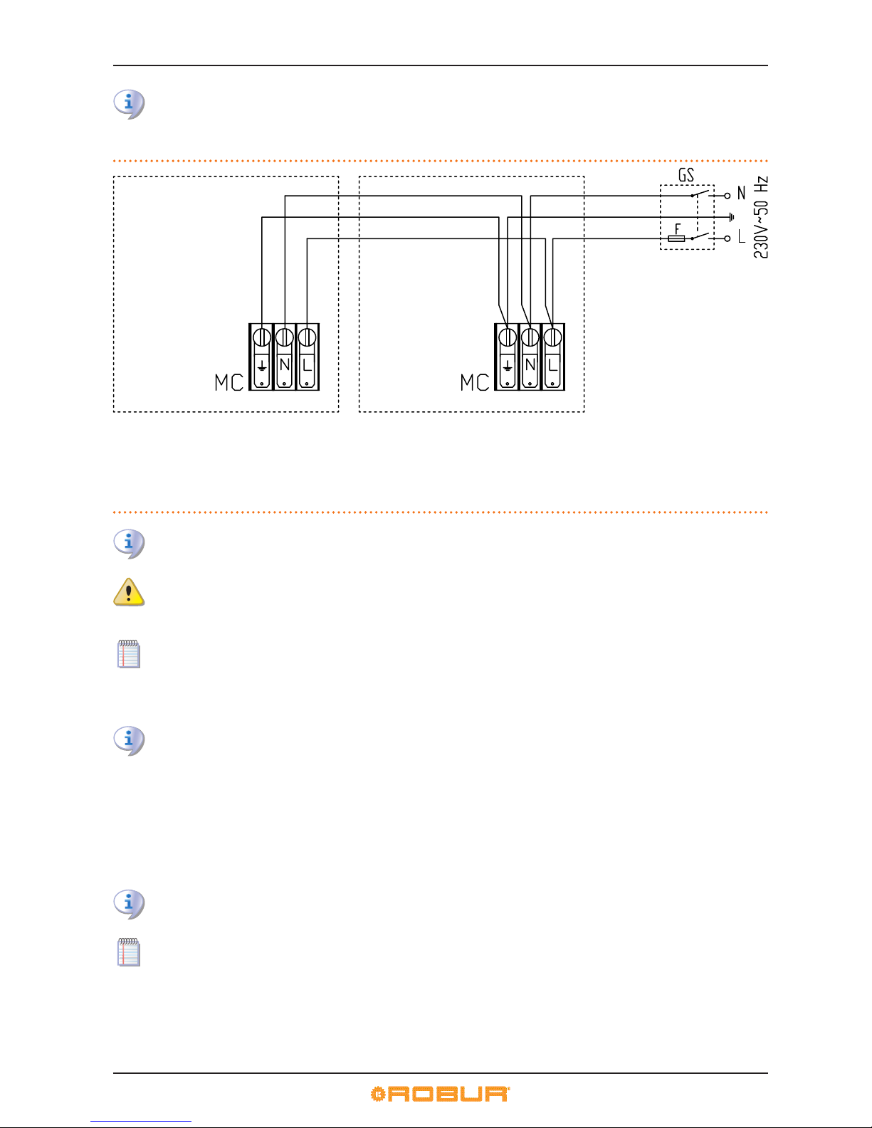
6 ELECTRICAL INSTALLATION
36
The insertion of relays or other electrical components inside the General Electrical Panel of the appliance is not permitted.
Do not activate the appliance if the hydraulic plant has not been lled.
Figure 6.4 – connection to electrical mains (230 V 1N - 50 Hz)
Example of connection of more than one appliance to the mains.
LEGEND
MC power terminal block
GS Master 2-pole power switch
F Fuse/s
N Neutral terminal
Ground ground terminal
L single-phase line terminal
Disconnect the appliance from the electrical power supply via the external disconnecting switch only after having performed the shutdown cycle (via the DDC or consent switch) and having waited for it to terminate (approximately 3 minutes).
Make sure the ground cable is longer than the live cables. In this way it will be the last wire to be pulled away if the mains
cable should accidentally be pulled, and will thus guarantee the ground connection. Do not use gas pipes to ground
electrical appliances.
A wiring error, as well as impeding the correct operation of the appliance, could also damage the electrical apparatus that
it contains.
6.2 ELECTRICAL CONNECTIONS FOR THE SYSTEM CIRCULATOR
The primary circulation pump/s must be controlled by the S70 board, or directly (via “N.O. contact” contacts) or indirectly (“OR” use of said contacts by BMS type external systems). Otherwise, the primary circulation pump/s must
be running permanently.
CONNECTION FOR CONTROLLING INDEPENDENT CIRCULATORS
This connection applies to hydraulic circuits which have a primary circuit circulator for each appliance (independent circulators)
installed on the plant. For example: 1 circulator/1 appliance; 5 circulators/5 appliances.
In such cases, for each appliance it may be sucient to install a single-phase water circulator (230 V AC), with power absorption less
than 700 W.
To make the circulator-appliance connections, proceed as follows (references to Figure 6.5→37):
You will need: the appliance connected hydraulically; single-phase water circulator (230 V AC), with power absorption less
than 700 W. Necessary equipment and materials.
In this case, the circulator’s 230 V AC power can be taken directly o the appliance’s internal terminal block (on the electrical
panel).
1. Remove the appliance's front panel and open the electrical panel by removing the bolts securing it.
2. Prepare a suitable cable for the connection.
3. Locate terminal block MC and the "NO Contact" terminals on controller S70 (SCH) inside the electrical panel, and hook up as
shown in the example.
Page 37
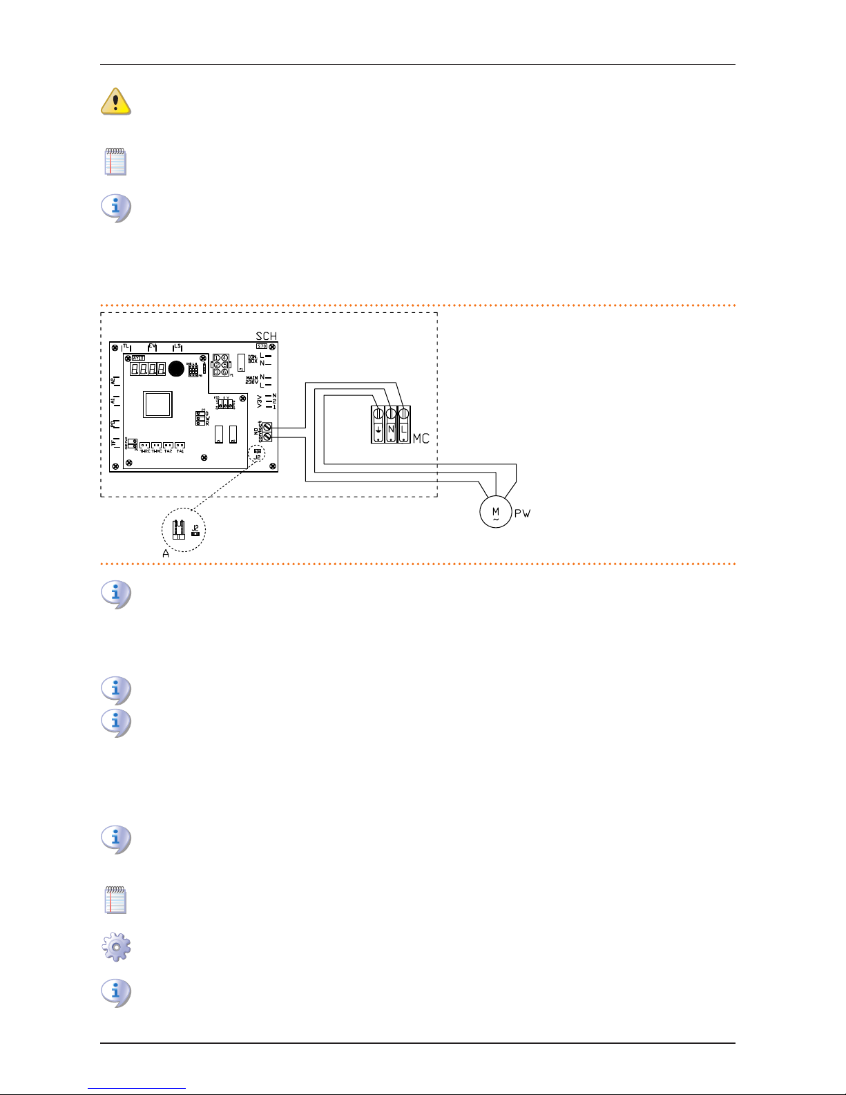
6 ELECTRICAL INSTALLATION
Installation, user and maintenance manual – AY Condensing line, AY Series
37
Make sure the ground cable is longer than the live cables. In this way it will be the last wire to be pulled away if the mains
cable should accidentally be pulled, and will thus guarantee the ground connection. Do not use gas pipes to ground
electrical appliances.
A wiring error, as well as impeding the correct operation of the appliance, could also damage the electrical apparatus that
it contains.
The "NO Contact" terminals are no voltage contacts with maximum power capacity of 700 W. These contacts control the
circulator shutdown delay (2 minutes after appliance shutdown). Check the position of jumper "J2", as follows:
4. Locate, on the appliance’s controller (SCH), jumper "J2" on the S70 (bottom right, below the "NO Contact" contacts) and make
sure that it is set as shown in detail "A" (jumper closed) of the gure.
5. On completion, restore the appliance to its fully assembled condition.
Figure 6.5 – Direct control of independent circulator
Example of "circulator-appliance" electrical connection with single-phase circulator (230 V AC), power less than 700 W.
LEGEND
SCH controller (AY10+S70)
NO contact system water circulator control
terminals (voltage free NO contact,
maximum power absorption 700 W)
J2 system water circulator control jumper
A detail of "closed" jumper
MC 230 V AC power terminal block
PW system water circulator (230 V AC;
<700 W)
If the circulator’s power is equal to or greater than 700 W, the installation technician must make the following modications (see gure):
▶
(point 3) <<... make the connections as shown in the example, but installing a relay for the control of the pump, managed via
NO-contact>>. Then:
▶
(point 4) <<Locate and open jumper "J2" as shown in detail "A" (jumper open) in the next gure 6.6→39>>.
Fit the relay inside the external electrical panel provided by the installation technician.
The insertion of relays or other electrical components inside the General Electrical Panel of the appliance is not permitted.
Do not activate the appliance if the hydraulic plant has not been lled.
CONNECTIONS FOR CONTROLLING A SHARED CIRCULATOR
This connection applies to hydraulic circuits which have a single primary circuit circulator for multiple appliance (shared circulator)
installed on the plant. For example: 1 circulator/3 appliances.
In such cases, a three-phase water circulator (400 V AC) may be required.
The choice of water circulator depends on the number of appliances being served as the specications of the system (water
ow rate, head, etc.) which are determined during the design process. Always follow the specications of the system design
documentation.
The following procedure refers to Figure 6.6→39, which gives an example of a three-phase circulator (400 V AC) connection.
To make the circulator-appliance connection, proceed as follows (references to Figure 6.6→39):
You will need: the appliances hydraulically connected; water circulator in line with the system specications (e.g.: threephase/400 V AC); external electrical panel congured by the installation technician. Necessary equipment and materials.
Make sure that the external electrical panel is equipped with a power switch (4-pole) with suitable motor thermal switch, a
secondary SELV safety transformer and control relay.
Page 38
6 ELECTRICAL INSTALLATION
38
1. On each appliance, remove the front panel and open the electrical panel by removing the bolts securing it.
2. Prepare a suitable cable for the connection.
3. Locate the "NO Contact" terminals on the S70 controller of each appliance and hook up as shown in the Figure.
Make sure the ground cable is longer than the live cables. In this way it will be the last wire to be pulled away if the mains
cable should accidentally be pulled, and will thus guarantee the ground connection. Do not use gas pipes to ground
electrical appliances.
A wiring error, as well as impeding the correct operation of the appliance, could also damage the electrical apparatus that
it contains.
The "NO Contact" terminals are no voltage contacts with maximum power capacity of 700 W. These contacts control the
circulator shutdown delay (2 minutes after appliance shutdown). Check the position of jumper "J2", as follows:
1. Locate, on each appliance's controller (SCH), jumper "J2" on the S70 (bottom right, below the "NO Contact" contacts) and make
sure that it is set as shown in detail "A" (jumper open) of the gure.
2. On completion, restore the appliances to their fully assembled condition.
The insertion of relays or other electrical components inside the General Electrical Panel of the appliance is not permitted.
Do not activate the appliance if the hydraulic plant has not been lled.
Page 39
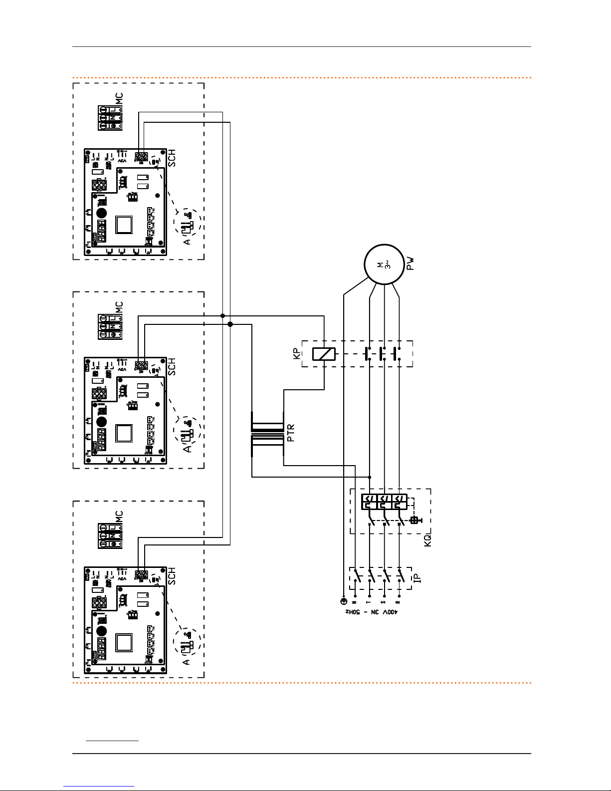
6 ELECTRICAL INSTALLATION
Installation, user and maintenance manual – AY Condensing line, AY Series
39
Figure 6.6 – Direct control of shared circulator
Example of electrical connection of a shared three-phase circulator (400 V AC).
LEGEND
SCH controller (AY10+S70)
NO contact system water circulator control terminals (voltage free NO contact, maximum power ab-
sorption 700 W )
J2 system water circulator control jumper
A detail of "open" jumper
MC 230 V AC power terminal block.
RST/N PHASE/NEUTRAL terminals for three-phase power (400 V AC)
ground ground terminal
IP system water circulator power switch
KQ motor protector or maximum current dierential circuit breaker for system water circulator
(400 V AC)
PTR SELV secondary safety transformer
KP NO (normally open) system water circulator control relay
PW system water circulator
6.3 CONNECTIONS FOR CONSENT SWITCH OPERATION
To operate, the appliance requires:
▶
consent switch for starting up and shutting down the appliance.
Page 40
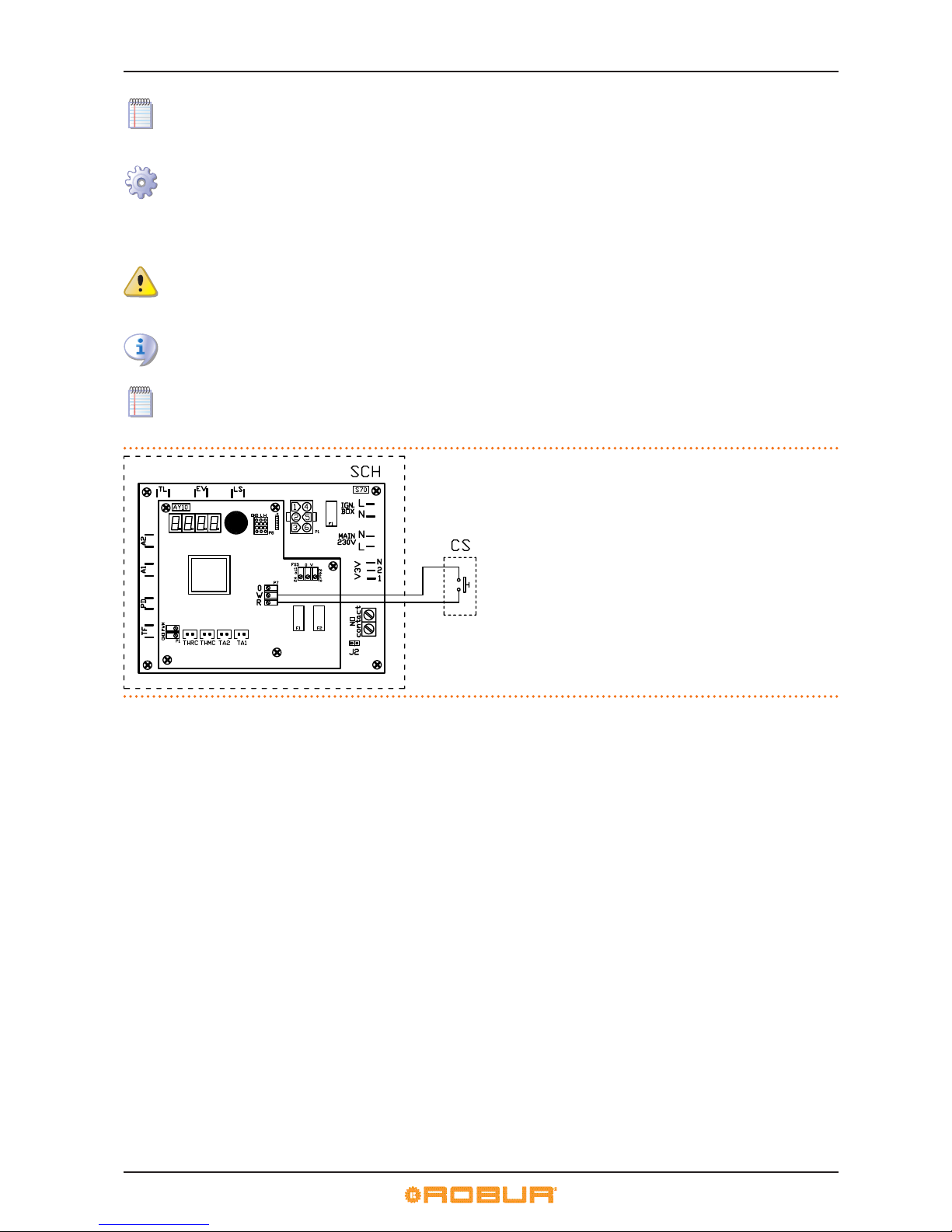
6 ELECTRICAL INSTALLATION
40
The consent switch (installation technician) can be an on/o switch, ambient thermostat, programmable timer, or other
such device.
To make the connection, proceed as follows (references to Figure 6.7→40):
You will need: the appliance connected hydraulically; consent switch. Necessary equipment and materials.
1. Remove the appliance's front panel and open the electrical panel by removing the bolts securing it.
2. Prepare a suitable cable for the connection.
3. Locate, on the appliance’s electrical panel, the consent terminals "R,W,0" (connector "P7") on the AY10 controller, and make the
connections between the consent switch and the R and W terminals as shown in the gure.
To start up and shut down the appliance in normal operation, always use the consent switch. Do not use the external power
switch.
4. On completion, restore the appliance to its fully assembled condition.
The insertion of relays or other electrical components inside the General Electrical Panel of the appliance is not permitted.
Do not activate the appliance if the hydraulic plant has not been lled.
If you intend to use a DDC, available as an accessory, refer to Paragraph 6.4→40.
Figure 6.7 – Series AY - operated by on-o consent switch
Example of operation consent connection.
LEGEND
SCH controller (AY10+S70)
W HOT consent terminal
R common terminal
CS consent switch
6.4 USE OF THE CCI/DDC
This paragraph is dedicated to the installation of the Direct Digital Controller (DDC). It gives full information on the installation and
connection of the device to the appliances.
Proceed as follows (qualied installation technician only):
1) How to t the CCI/DDC.
2) How to supply power to the CCI/DDC.
3) How to connect the CCI/DDC to the appliance.
Figure 6.8→41 gives rear and front views of the DDC along with its electrical connections. The following connectors are required:
▶
4 pole connector (part reference "AL") for 24 V AC power.
▶
6 pole CAN BUS connector (part reference "P8") for connecting the DDC with the appliance.
Page 41
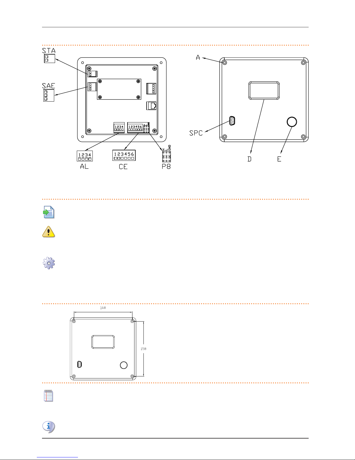
6 ELECTRICAL INSTALLATION
Installation, user and maintenance manual – AY Condensing line, AY Series
41
Figure 6.8 – CCI/DDC
Front and rear views with detail of electrical connections.
LEGEND
STA ambient temperature probe - 2-pole connector
SAE external alarm systems - 3-pole connector
AL power supply 24 V AC - 4-pole connector
CE external consents - 6-pole connector
P8 CAN network connector (orange)
SPC 232 serial connection to PC - 9-pole connector
A mounting holes CCI/DDC
E Encoder
D Display
For instructions regarding other connections (optional: to be done by the electrical installation technician in accordance
with the user's requirements) and, in general, for the DDC installation and user instructions, see the two booklets in question.
Before installing the DDC, disconnect the appliance from its power supply with the power switch in its electrical panel.
1) How to t the CCI/DDC
The DDC in indoor installations must be applied to a panel as follows (see Figure 6.9→41):
You will need: the appliance and the DDC disconnected from the electricity supply. Necessary equipment and materials.
1. Make a rectangular opening 155 mm wide and 151 mm high;
2. Locate the DDC on this hole and mark the 4 points where the holes are to be made to x it. See the gure.
3. Drill no. 4 holes of dia. 4 mm.
4. Proceed with the operation of making fast the DDC on the opening of the panel using the screws and nuts supplied.
Figure 6.9
Centre distances of mounting holes for CCI/DDC.
LEGEND
Holes for mounting CCI/DDC’s to panel
horizontal: 168 mm
vertical: 158 mm
The DDC's operating temperature range is 0 - 50 °C. If the temperature of the room where the DDC is installed falls below
zero, it continues to operate correctly to -10 °C. However, its LCD display may not be able to display data.
2) How to supply power to the CCI/DDC
The DDC requires a low voltage power supply (24 V) with 230/24 V AC, 50/60 Hz safety transformer; the minimum power
requirement is 20 VA.
Page 42
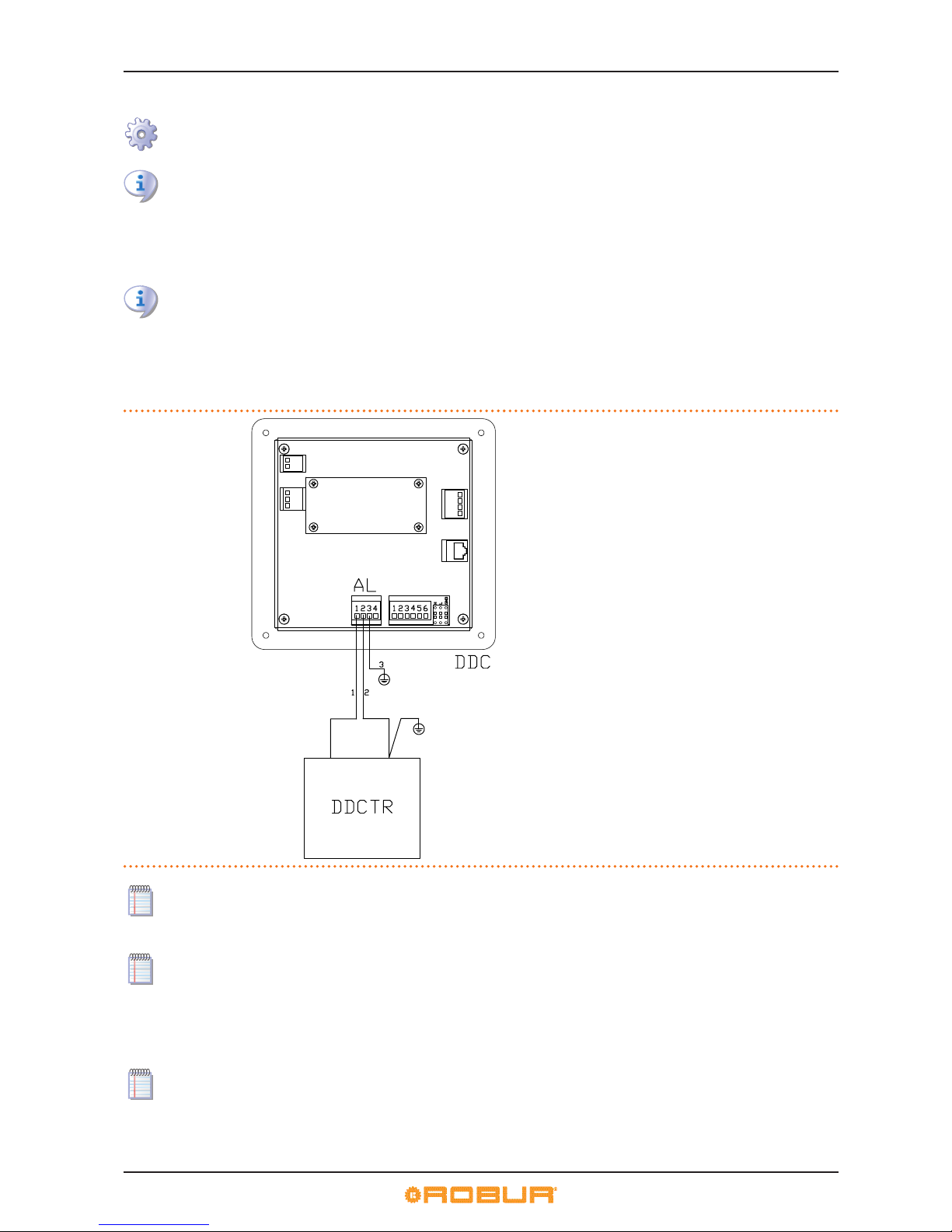
6 ELECTRICAL INSTALLATION
42
To power the DDC (o a transformer located in an external panel), proceed as follows (see example in Figure 6.10→42):
You will need: the appliance disconnected from the electricity supply; the external electrical panel congured by the installation technician. Necessary equipment and materials.
Make sure that the external electrical panel is equipped with a 230/24 V AC - 50/60 Hz safety transformer, of at least 20 VA
power.
1. Remove the DDC's back panel by undoing the 4 bolts securing it (detail "A" - Figure 6.8→41).
2. Use an electrical power cord (minimum cross section: 2x0.75 mm2).
3. Pass the power cord (DDC side) through the hole in the DDC's cover and hook up as shown in the example, with the following
polarities: terminal 1 = 24 V; terminal 2 = 0 V; terminal 3 = ground.
Terminal 3 of the DDC's 4-pole connector (AL) must be, in any case, connected to a ground plant (r≤0,1Ω). Terminal 2 of the
DDC is connected internally to terminal 3, and is thus also connected to ground. Make the grounding connection on the
transformer terminal connected to terminal 2 of the DDC. if the transformer already has one wire grounded, it must be connected to this terminal.
4. On completion, close the DDC's back panel with the 4 bolts.
Figure 6.10 – CCI/DDC - electric supply
CCI/DDC electric supply from external transformer.
LEGEND
DDC CCI/DDC
AL supply 4 poles connector
1 clamp and wire for 24 Vac supply
2 clamp and wire for 0 Vac supply
3 clamp and wire for ground contact
(required connection)
DDCTR safety transformer
- (230/24 Vac 50/60 Hz)
If the CAN BUS cable has already been connected to the DDC (next procedure "3) How to connect the CCI/DDC to the appliance"), take care with the 4 mm CAN BUS cable shielding eyelet (or two eyelets): use the retainer screw next to the CAN BUS
socket (bottom right) to secure the eyelet (or both eyelets) as shown in Figure 6.13→44.
The DDC is equipped with a backup battery which retains the memory settings in case of power failure. The battery has a
service life of around 7 years, after which it must be replaced by the Robur TAC.
3) How to connect the CCI/DDC to the appliance
The appliance and the DDC communicate with each other via the CAN network (data network), which is characterised by a number
of nodes, connected by the CAN BUS cable.
By a node of the data network we mean any device (DDC, appliance or individual module) connected to it. Each network
consists of 2 terminal nodesand, if required, a certain number of intermediate nodes. A device is considered to be a terminal
node when it is connected to only one other device. A device is considered to be an intermediate node when it is connected
to two other devices. Appliances, individual modules and DDC's may act equally as terminal or intermediate nodes. See
Figure 6.11→43.
Page 43
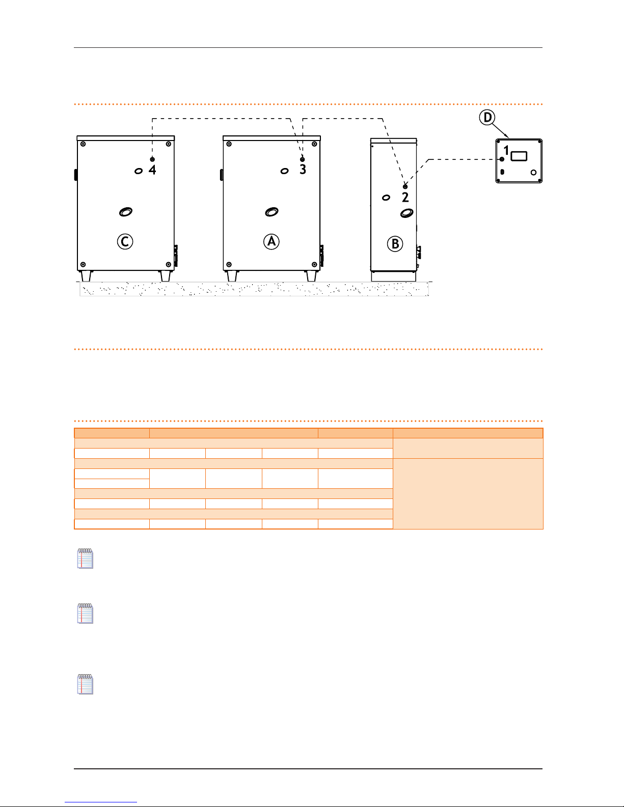
6 ELECTRICAL INSTALLATION
Installation, user and maintenance manual – AY Condensing line, AY Series
43
The CAN network can link together a maximum of: 3 DDC's, each of which is in turn connected to 16 hot only modules + 16 cold only
modules or 16 hot/cold modules.
Figure 6.11 – CAN network
Example of network with 4 nodes (1 DDC + 3 appliances).
LEGEND
A appliance (GA/GAHP)
B appliance (AY)
C appliance (GA/GAHP)
D DDC
1 CAN-BUS network terminal node
2 CAN-BUS network intermediate node
3 CAN-BUS network intermediate node
4 CAN-BUS network terminal node
> CHARACTERISTICS OF THE CAN BUS CABLE
The cable to be used must be suitable for CAN BUS applications.
The following table gives details of some types of CAN bus cable, grouped according to the maximum distance covered by each
single type.
Table 6.2 – CAN BUS cables type
CABLE NAME SIGNAL / COLOR MAX LENGTH Note
Robur
Ordering Code O-CVO008
ROBUR NETBUS H= BLACK L= WHITE GND= BROWN 450 m
Honeywell SDS 1620
In all cases the fourth conductor should not be used
BELDEN 3086A
H= BLACK L= WHITE GND= BROWN 450 m
TURCK type 530
DeviceNet Mid Cable
TURCK type 5711 H= BLUE L= WHITE GND= BLACK 450 m
Honeywell SDS 2022
TURCK type 531 H= BLACK L= WHITE GND= BROWN 200 m
Example types of cables used to connect the CAN network.
For overall distances to cover of ≤200 m and networks with a maximum of 6 nodes (a typical example: 1 DDC + 5 devices), a
simple 3 x 0.75 mm2 shielded cable may be used.
As shown in Table 6.2→43, the CAN connection requires a CAN bus cable with 3 wires. If the available cable has more than 3 coloured
wires, use the wires with the colours indicated in 6.2→43 and cut the remaining ones.
The ROBUR NETBUS cable is available as an accessory (see Section 8→58).
> CONNECTION PROCEDURE
Instructions for the specic operations to be carried out for the connection of the CAN bus cable follow:
▶
Step A: connect the CAN-BUS cable to the CCI/DDC.
▶
Step B: connect the CAN-BUS cable to the appliance.
The two steps must done in both cases illustrated in Figure 6.17→48 (wiring diagram for 1 DDC connected to a single appliance) and Figure 6.18→49 (wiring diagram for 1 DDC connected to multiple appliances).
Step A: connect the CAN-BUS cable to the CCI/DDC
The CAN bus cable connects to the specic orange connector supplied with the DDC, as shown in Figure 6.12→44.
Page 44
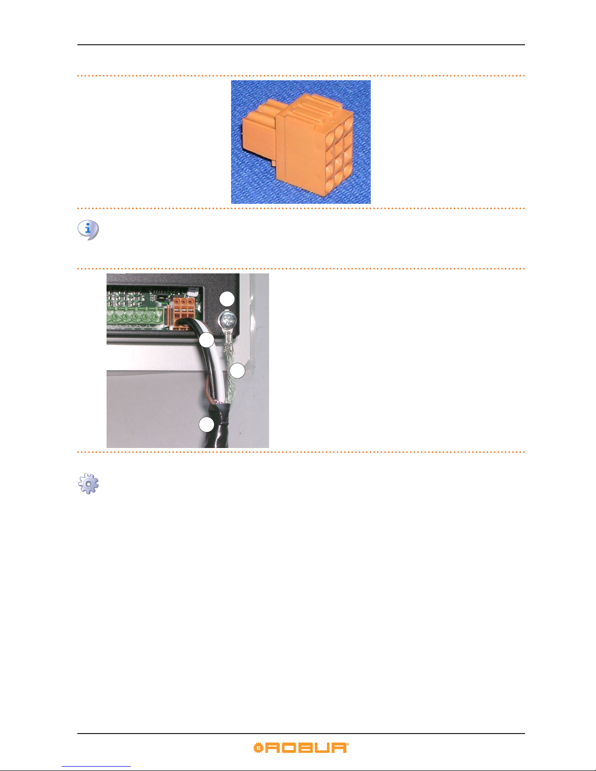
6 ELECTRICAL INSTALLATION
44
Figure 6.12
Orange connector for CAN-BUS connection to CCI/DDC (supplied with CCI/DDC).
The DDC is equipped with jumpers that must be moved in order to take on the congurations of terminal node and interme-
diate node (Figure 6.14→45). The DDC is supplied with the jumpers CLOSED (detail "A" Figure 6.14→45).
Figure 6.13 – Connection from CAN BUS to connector P8
Connection detail of cable CAN BUS.
LEGEND
A Insulating tape to protect board/shield
B CAN BUS cable wires
C CAN bus cable shield
D terminal and screw for xing
To connect a CAN BUS cable to a DDC, proceed as follows (references in Figure 6.14→45):
You will need: DDC not powered up. Necessary equipment and materials.
1. Depending on the type of node being congured, set the DDC's jumpers as shown in detail "A" or detail "B" in the gure. If
necessary, open the DDC’s back panel (4 bolts); after the jumpers have been correctly positioned, close the cover again and
retighten the 4 bolts;
▶
if the DDC is an intermediate node on the network (with no. 6 wires in the orange connector): set the jumpers as shown in detail
"B" of the gure: Jumpers OPEN;
▶
if the DDC is a terminal node on the network (with no. 3 wires in the orange connector): set the jumpers as shown in detail "A"
of the gure: Jumpers CLOSED.
Page 45
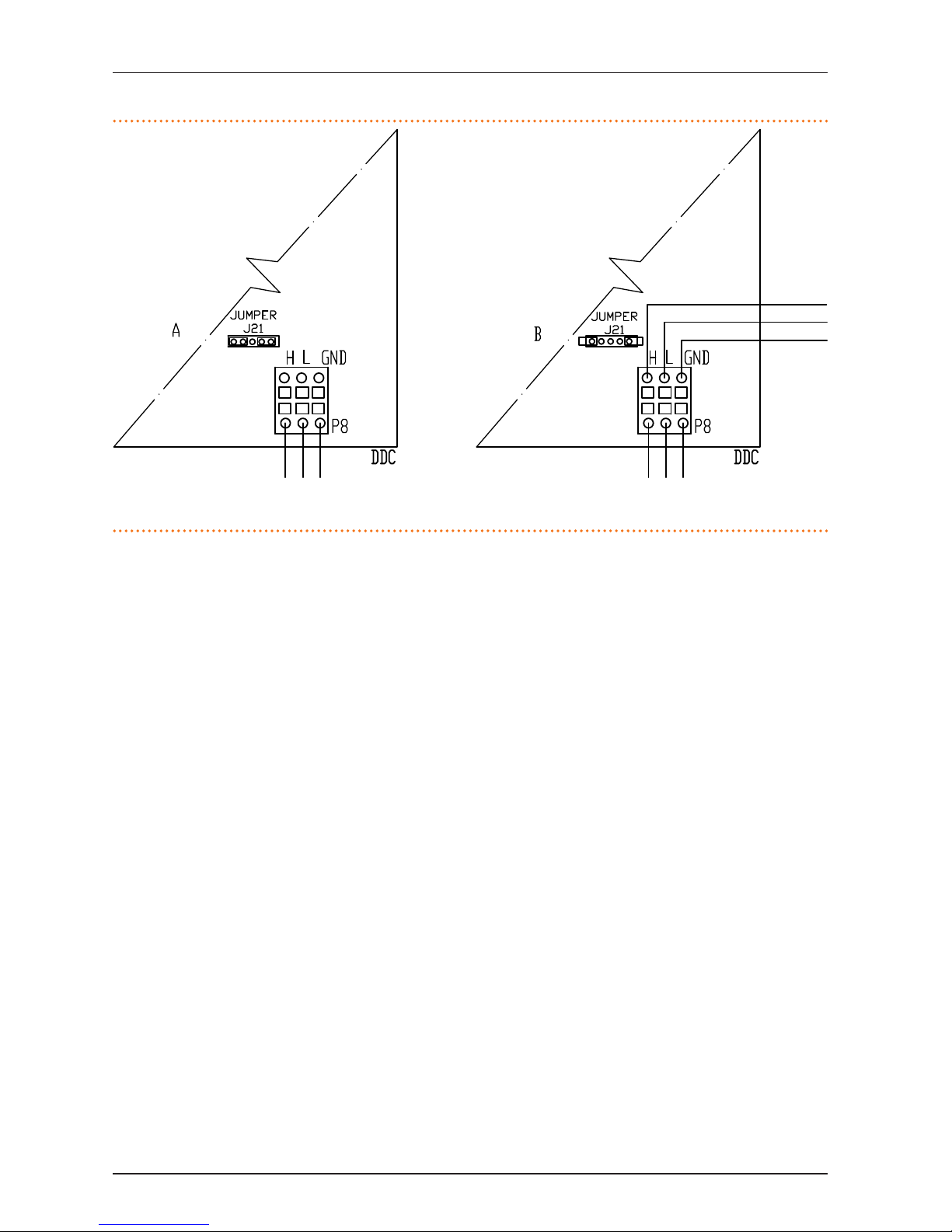
6 ELECTRICAL INSTALLATION
Installation, user and maintenance manual – AY Condensing line, AY Series
45
Figure 6.14 – detail wires and jumpers J21 - terminal/intermediate node CCI/DDC
Detail terminal and intermediate node: jumpers position J21: "closed" - "open".
LEGEND
DDC CCI/DDC
J21 Jumper CAN-BUS in CCI/DDC board
A detail case "terminal node" (3 wires; J21=jumper "closed")
B detail case "intermediate node" (6 wires; J21=jumper "open")
H,L,GND data signal wires
2. Prepare the orange connector (remove from envelope).
3. Cut a length of cable, long enough to allow it to be installed without kinking.
4. Having chosen one end of the length of cable, remove the sheath from a length of approximately 70-80 mm, taking care not
to cut the wires contained inside, the shielding (metallic shield and/or aluminium sheet) and, if present, the bare connector in
contact with the shield and the wires contained within.
5. Roll the shielding and connect it to a 4-mm eyelet terminal, as illustrated in Figure 6.13→44, details C and D. Now proceed as
follows:
6. Connect the three coloured wires to the orange connector, as shown in detail "A" in the gure. Observe the terminal markings
L, H, GND (on the DDC at the base of the socket "P8") which are given both in Table 6.2→43, and in the gure:
▶
if the DDC is an intermediate node on the network, also complete step "7";
▶
if the DDC is a terminal node, skip directly to step "8".
7. Intermediate nodes only: repeat the operations from step "1" to step "4" for the other length of CAN bus cable required. Now
proceed with step "5" and, to connect the cable to orange connector, refer to detail "B" in the gure. Then proceed to point "8".
8. Fit the orange connector, with the wires attached, rst through the slot in the DDC’s cover and then into the socket on the
DDC itself.
9. Use the rear cover bolts located near the CAN BUS socket to secure the 4-mm eyelet (or 2 eyelets) (detail D, Figure 6.13→44).
The cable should be secured against pulling out.
Step B: connect the CAN-BUS cable to the appliance
The CAN BUS cable must be connected to the orange socket on the machine’s on-board controller (see detail "D" in Figure 6.15→46).
Page 46
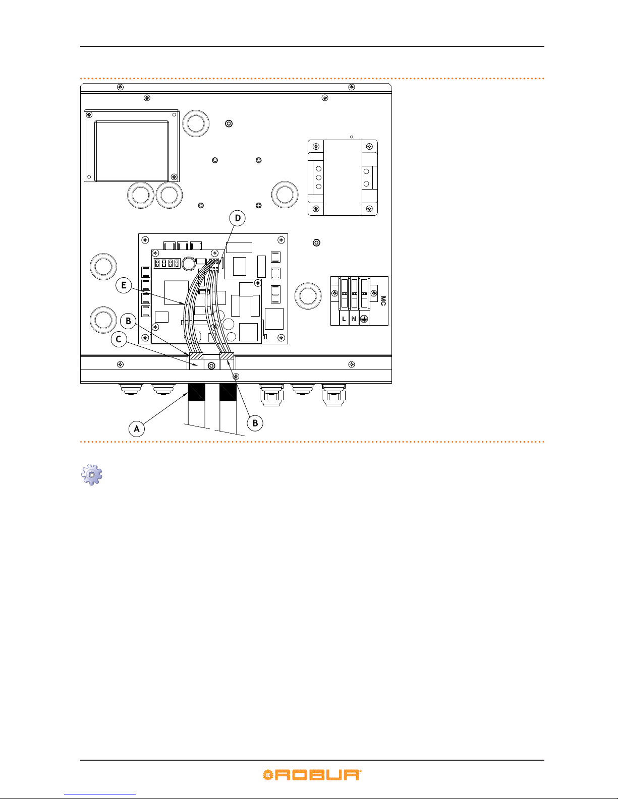
6 ELECTRICAL INSTALLATION
46
Figure 6.15 – Connection of CAN BUS cable to connector P8 on controller AY10
Detail of cabling of CAN BUS cable to controller AY10.
LEGEND
example of connection of 2 CAN BUS cables
(the appliance is an intermediate node)
A insulating tape to protect board/screen
B CAN BUS cable shielding
C cable bracket (for 2 CAN BUS cables)
D orange connector for CAN BUS cable
terminals
E wires (no. 6) of CAN BUS cables
To connect the CAN BUS cable to the DDC, proceed as follows (references in Figure 6.15→46):
You will need: appliance not powered up. Necessary equipment and materials.
1. Remove the front panel of the appliance and the cover of the electrical panel.
2. Cut a length of cable, long enough to allow it to be installed without kinking.
3. Having chosen one end of the length of cable, remove the sheath from a length of approximately 70-80 mm, taking care not
to cut the wires contained inside, the shielding (metallic shield and/or aluminium sheet) and, if present, the bare connector in
contact with the shield and the wires contained within.
4. If the cable is too thin to be held in place in the cable holder bracket (detail C), make it thicker by wrapping insulating tape
around it on the sheath in the area adjacent to the stripped part (to an approximate diameter of 12-13 mm).
5. Pull back the shielding in the sheathe; apply electrician’s tape to the end of the shielding as pulled back (detail A).
6. Pull the orange connector (detail D) out of socket "P8" on the controller.
7. Connect the three coloured wires to the orange connector, as shown in detail "A" in Figure 6.16→47. Observe the terminal
markings L, H, GND (on the board at the base of the socket "P8") which are given both in Table 6.2→43, and in Figure 6.16→47:
▶
if the appliance is an intermediate node on the network, also complete step 8;
▶
if the appliance is a terminal node, skip directly to step 9.
8. Intermediate nodes only: repeat the operations from point 2 to point 5 for the other length of CAN bus cable required. Now
proceed with step 7 and, to connect the cable to connector P8, refer to detail "B" in Figure 6.16→47. Then proceed to point 9.
9. Fit the orange connector, with wires attached, into the P8 socket on the board.
10. Fix the CAN BUS cable (or two cables, according to the type of node being connected) to the cable xing bracket so that the
rolled-back sheathing makes solid contact with the metal bracket. The cable should be secured against pulling out.
11. Now, depending on the type of node being congured, set the jumpers on the appliance’s controller as shown in detail "A" or
detail "B" in Figure 6.16→47. Proceed as follows:
▶
If the appliance is an intermediate node on the network (with no. 6 wires in the orange connector): set the jumpers as shown
in detail "B" of the gure: Jumpers OPEN.
▶
If the appliance is a terminal node on the network (with no. 3 wires in the orange connector): set the jumpers as shown in detail
"A" of the gure: Jumpers CLOSED.
Page 47
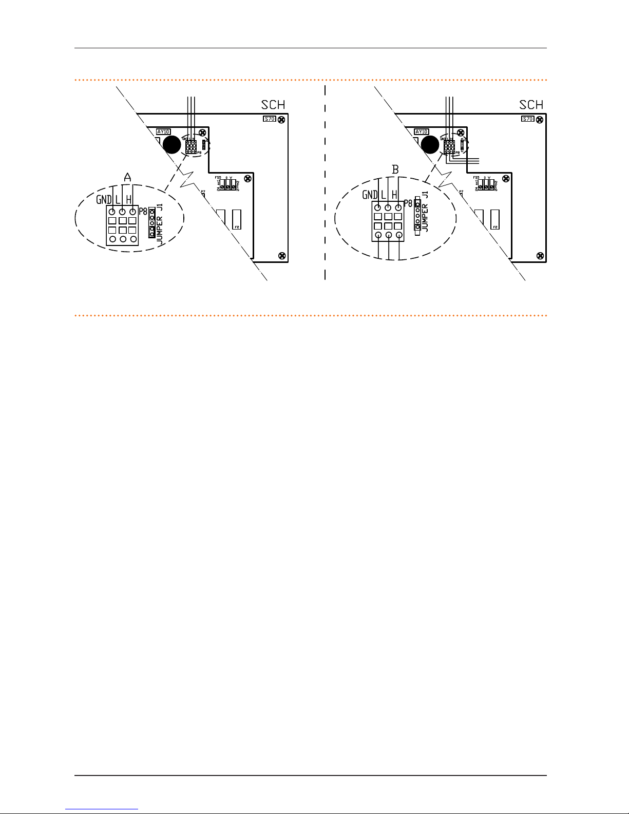
6 ELECTRICAL INSTALLATION
Installation, user and maintenance manual – AY Condensing line, AY Series
47
Figure 6.16 – detail of wires and jumpers J1 - appliance terminal/intermediate node
Detail of terminal and intermediate node, jumper position J1: "closed" - "open".
LEGEND
SCH controller (AY10+S70)
J1 CAN BUS jumper on AY10 controller
A detail of "terminal node" case (3 wires; J1=jumper "closed")
B detail of "intermediate node" case (6 wires; J1=jumper "open")
H,L,GND data signal wires
12. Now close the electrical panel and ret the front panel of the appliance.
Page 48
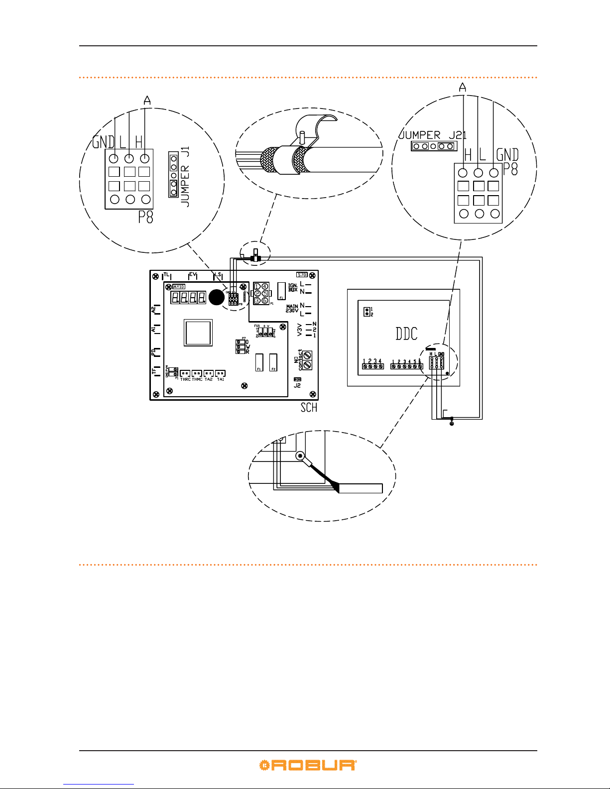
6 ELECTRICAL INSTALLATION
48
Figure 6.17 – CAN BUS connection for single appliance systems
CAN BUS cable connection between DDC and one appliance.
LEGEND
DDC digital control panel
SCH controller (AY10+S70)
J1 CAN BUS jumper on AY10 controller
J21 CAN BUS jumper on DDC board
A terminal node connection (3 wires; J1 and J21 = "closed")
H,L,GND data signal wires
Page 49
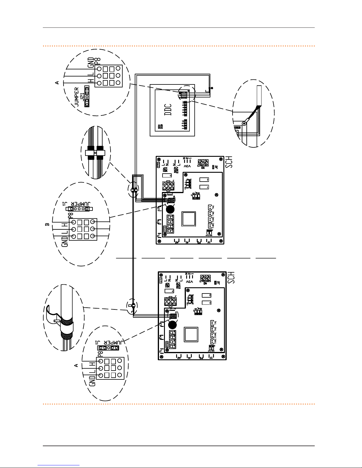
6 ELECTRICAL INSTALLATION
Installation, user and maintenance manual – AY Condensing line, AY Series
49
Figure 6.18 – CAN BUS connection for multiple appliance systems
CAN BUS cable connection between 1 DDC and multiple appliances.
LEGEND
DDC digital control panel
SCH controller (AY10+S70)
J1 CAN BUS jumper on AY10 controller
J21 CAN BUS jumper on DDC board
A terminal node connection (3 wires; J1 and J21 =
"closed")
B intermediate node connection (6 wires; J1="open")
H,L,Gnd data signal wires
Page 50
7 INITIAL ACTIVATION AND MAINTENANCE
50
7 INITIAL ACTIVATION AND MAINTENANCE
In this section you will nd the following information:
▶
Indications required by the authorized Robur Technical Assistance Centre (TAC) in order to carry out the entire procedure of rst
start-up of the appliance (see Paragraph 7.1→50);
▶
Indications regarding maintenance operations of the appliance (Paragraph 7.2→53): general information and warnings; general
indications regarding checks, controls and cleaning.
▶
Instruction for the Robur TAC or gas type conversion (Paragraph 7.3→54).
Before proceeding with the operations described in this section, the installation technician concerned is invited to read
Paragraph 3.1→7. in regard to switching the appliance on and o, refer to Paragraph 4.1→13. If the appliance is connected
to a DDC (and the DDC is in controller mode), for the phases of activation and deactivation of the appliance it is necessary to
refer to the two manuals dedicated to the DDC itself.
7.1 PROCEDURE FOR FIRST START UP
The initial activation procedure is composed of the following (main) steps.
Step 1: preliminary verication of plant compliance.
Step 2: verication/regulation of combustion parameters and rst ignition.
Step 3: regulation of plant operating parameters.
The entire procedure for the initial activation of the appliance must only carried out by an authorised Robur Technical Assistance Centre (TAC). The product's guarantee may be void if the procedure is not carried out by a Robur TAC.
Before leaving the factory, the appliance has been thoroughly tested.
Step 1: preliminary verication of plant compliance
The Robur TAC technician must:
▶
Check that the whole installation has been realized in accordance with its design, following the manufacturer's instructions and
respecting current legislation. The design must have been drawn up by a professional specier.
▶
Check personally that all of the connections (hydraulic/gas and electrical) of the appliance (and of the Direct Digital Controller, if
connected to the appliance) have been made correctly.
▶
Check that the installation is actually compliant as per the Declaration of Conformity provided by the installer to the owner.
The Declaration of Conformity CERTIFIES that the installation is compliant with current regulations. This Declaration is a
mandatory document and as such it must be provided by the installer to the owner.
▶
Check that the water pressure and ow in the hydraulic circuit and the static gas supply network pressure are correct, as indicated by the manufacturer.
▶
Check that the electrical power supply is 230V 50Hz
▶
Check that the air/fumes pipes are properly connected.
▶
Check that the fumes condensate discharge is properly installed.
▶
Check that the safety clearances have been observed, as shown in Figure 5.1→19.
If all the conditions listed above exist, the TAC can proceed with the operations, performing the "initial activation" of the appliance.
If any non-compliant elements arise during the initial verication, the TAC may choose not to proceed with the operation of "initial
activation".
In this case, the Robur TAC technician must:
▶
Report the user/installer of any installation anomaly.
▶
Report the user/installer of any situation that is potentially hazardous for the appliance and for people.
▶
Report of any missing documentation relevant to the installation.
▶
According to the reports made, advise any corrective action to be taken at the installer's care in order to proceed with the "rst
start up".
It is the responsibility of the user/installation technician to carry out any corrective measures on the plant indicated by the
TAC. Following such corrective measures performed by the installation technician, the TAC will assess the plant again. At
this point, if, in the opinion of the TAC, safety and compliance conditions exist, the TAC must carry out the "initial activation".
Plant situations that are hazardous for people and for the appliance. If one of the following hazardous situations arises, the
TAC must not carry out the "initial activation":
▶
appliance installed in improper conguration (e.g.: type B in closed and insuciently ventilated area);
▶
appliance installed close to combustible substances or surfaces or in any case in conditions of bad accessibility or not allowing
safe maintenance operations;
Page 51

7 INITIAL ACTIVATION AND MAINTENANCE
Installation, user and maintenance manual – AY Condensing line, AY Series
51
▶
control of switching on and o of the appliance not via the DDC but via the external switch connecting the appliance to the
power supply mains ("GS", tted by the electrical installation technician on a suitable panel);
▶
damages or failures of the appliance due to transportation or installation;
▶
smell of gas due to probable leaks from the plant itself and in any case all situations that are due to non-compliant plants, considered (after on-site evaluations) potentially hazardous.
Plant anomalies. If any of the following situations exists, the authorized technician may carry out the "rst start up" at his
choice, but the appliance must be left o until the anomalies are removed:
▶
installations (not potentially hazardous) not carried out according to sound workmanship practices, installations (not potentially
hazardous) not complying with current national and local regulations;
▶
installations (not potentially hazardous) not carried out according to good workmanship practices, not complying with the instructions provided by the manufacturer;
▶
installations that can cause operational troubles on the appliance.
Step 2: verication/regulation of combustion parameters and rst ignition
During the initial activation procedure, the combustion parameters must be checked and set ONLY by a Robur TAC. In this
stage, NEITHER the user NOR the installation technician is authorised to perform such operations, and in so doing may invalidate the guarantee of the appliance.
The appliance is delivered already regulated for the type of gas requested. Anyway, the combustion parameters must ALWAYS be
checked and set during the rst start up.
The type of gas for which the appliance is set is given on the sticker on the internal panel and on the appliance's original
packaging.
To check and set the combustion parameters, proceed as follows, with reference to Figures 7.1→52 and 7.2→52 and Table 7.1→53.
You will need: appliance not powered up: master power switch and gas cock set to OFF. outer front panel (H) removed.
Necessary equipment and materials. DDC (if installed) already connected electrically.
1. Open the internal panel (E) by undoing its bolts.
2. Open the plant gas supply valve to the appliance and make sure that there is no smell of gas (indicating possible leaks).
In case of gas leaks, go back over Step 1 above and restore the system to compliancy.
3. Once you are sure there are no gas leaks, close the gas cock.
Now check the static and dynamic mains gas pressure: if the system has multiple appliances, this check (steps "4" to "10")
need only be done once, so long as it is done with the appliance furthest from the mains connection; for the other appliances, skip directly from step "3" to step "12".
4. Undo the bolt sealing the inlet gas pressure socket (D).
5. Connect the manometer to the gas intake (mains pressure).
6. Open the gas valve.
7. Read the value of the static network pressure on the manometer and check that the value read is equal to that stated in Table
5.2→24 (with tollerance ±15%).
8. Close the master power switch (GS) on the external electrical panel.
9. Switch the appliance on. Wait for the appliance to stabilise (3 minutes from switching on) and then proceed to step "10".
If the appliance does not switch on, remove the side panel (N), remove the cap (L) and use a athead screwdriver through
hole (G) to turn the ow regulator screw 3 turns counterclockwise ; reinstall the cap (L) and repeat step "9".
10. Read the dynamic mains pressure on the pressure gauge and check that the value is in the range specied at step "7". Now
switch the appliance o.
If the dynamic network pressure does not corresponde to the value stated in Table 5.2→24 (with tollerance ±15%), write
down the fault and, at the end of the procedure, notify the installer/user. Received the notify, the user must not operate the
appliance until the fault has been solved and the manufacturer's specications are met (see Step 1 once again).
11. Restore the appliance by screwing the gas intake seal screw back in.
12. Close the appliance's internal panel (E).
13. Fit a combustion products probe in one of the points provided fro this purpose on the external fumes equipment.
14. Switch the appliance on and wait for it to stabilise (3 minutes).
15. With reference to Table 7.1→53 and the fumes analyser reading, check that the CO2 content percentage of the combustion
products is within ±0,2 of the characteristic value for the gas being used.
16. If the value is in the correct range, go to step "17". Otherwise, remove the side panel (N) and follow the instructions given in
steps "25" and "26", including the note, in the procedure given in Paragraph 7.3→54.
17. Enter menu 2 and execute action "23": timed forcing of the appliance to minimum power (8.0 kW). The procedure to run the
actions of menu 2 is specied in this Paragraph “Step 2".
Page 52
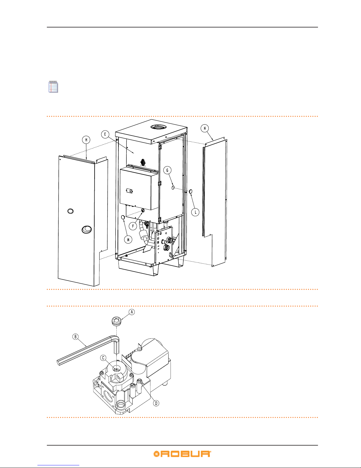
7 INITIAL ACTIVATION AND MAINTENANCE
52
18. With reference to Table 7.1→53 and the fumes analyser reading, check that the dierence between the CO2 percentage observed in step “15” and the current reading corresponds to the
delta CO
2 characteristic of the gas being used.
Example: having set, in step "15", a CO2 content of 9.5% for G20 gas, at step "18" the reading should be 9.0% (=9.5%-0.5%).
19. If the dierence satises the
delta CO
2 requirement, go to the next step. Otherwise, follow the instructions given in steps "30" and
"35", including the note, in the procedure given in Paragraph 7.3→54.
20. Enter menu 2 and execute action "25": forced stop to cancel the preceding forced operation and return to the initial operational conguration.
After 30 minutes of operation the appliance automatically cancels the preceding forced power mode. To anticipate this timing, select and execute action "25" in menu 2.
21. Switch o and completely restore the appliance.
Figure 7.1 – Checking and adjusting the combustion parameters
Procedure for checking and adjusting the combustion parameters.
LEGEND
E front panel interior
F access hole for OFFSET regulator
G access hole for ow rate regulator
H front panel exterior
L access plug for ow rate regulator
M access plug for OFFSET regulator
N external side panel
Figure 7.2 – Gas valve
Gas valve Honeywell VK 4115V
LEGEND
A Cap
B Torx wrench TX40
C CO2 adjuster screw
D Mains gas pressure tting
Page 53

7 INITIAL ACTIVATION AND MAINTENANCE
Installation, user and maintenance manual – AY Condensing line, AY Series
53
Table 7.1 – Gas nozzles and content of CO2
Gas type G20 G25 G25.1 G27 G2.350 G30 LPG G31
Nozzle code - 176 179 178 178 - 177 177 177
Nozzle diameter mm 6.20 7,30 7,60 7,60 - 4.45 4.45 4.45
Parameter value "45" - 0 0 0 0 0 1 1 0
CO2 content % 9.4 9.4 10,7 9,35 9,15 12,4 11.4 10.6
Delta CO2 between Max and Min potential % 0,5 0,5 0,5 0,45 0.35 0,9 0,9 0,4
In the rst start-up stage, on the display of the controller of the appliance (and/or on the display of the DDC, if connected),
an operating code might be visualized. If the operating code is generated by the controller of the appliance, see the list of
codes in Table 9.1→59; if the operating code is generated by the DDC, see the list of codes given in the "installation technician manual - manual 1" of the DDC (supplied with the unit).
Successful rst start-up ONLY certies the correct operation of the appliance (and of the DDC, if connected). It does NOT
certify that the plant complies with current regulations.
OPERATIONS IN MENU 2
▶
FORCING TO MINIMUM POWER (ACTION "23"):
You will need: the display showing "2.20" (see point "3" of procedure "HOW TO ACCESS THE MENUS" - Paragraph "4.3→15").
1. Turn the knob clockwise until the display shows parameter "2.23".
2. Press the knob to display the ashing force to minimum power request: "P_L1".
3. Press the knob again to execute the forcing. The request stops ashing, and the display shows “2.23” again. The forcing operation has been performed.
4. To exit the menu, turn the knob clockwise until “2.E” displays, and press it to return to the menu selection: "2.".
5. To exit the menu selection, turn the knob clockwise until “E” displays, and press it to exit.
▶
FORCING TO MAXIMUM POWER (ACTION "24"):
You will need: the display showing "2.20" (see point "3" of procedure "HOW TO ACCESS THE MENUS" - Paragraph "4.3→15").
1. Turn the knob clockwise until the display shows parameter: "2.24".
2. Press the knob to display the ashing force to minimum power request: " P_H1".
3. Press the knob again to execute the forcing. The request stops ashing, and the display shows "2.24" again. The forcing operation has been performed.
4. To exit the menu, turn the knob clockwise until “2.E” displays, and press it to return to the menu selection: "2.".
5. To exit the menu selection, turn the knob clockwise until “E” displays, and press it to exit.
▶
CANCELLING POWER FORCING (ACTION "25"):
You will need: the display showing "2.20" (see point "3" of procedure "HOW TO ACCESS THE MENUS" - Paragraph "4.3→15").
1. Turn the knob clockwise until the display shows parameter: "2.25".
2. Press the knob to display the ashing cancel forcing request: "UnF1".
3. Press the knob again to execute the cancel operation. The request stops ashing, and the display shows "2.25" again. The cancel operation has been performed.
4. To exit the menu, turn the knob clockwise until “2.E” displays, and press it to return to the menu selection: "2.".
5. To exit the menu selection, turn the knob clockwise until “E” displays, and press it to exit.
Step 3: regulation of plant operating parameters
Regulation of operating parameters of the plant occurs via the controller (see Paragraph 5.9→29) or via the DDC (if connected).
In this phase it may be necessary to check the settings of parameters "156", "180" and "182", which are closely linked to the
system requirements (see instructions "SPECIAL PARAMETER SETTINGS" in Paragraph 5.9→29).
If the appliance is connected to a Direct Digital Controller (DDC), for operations regarding the regulation of plant operating
parameters according to the user's requirements, refer to the DDC’s manual (nal user manual - manual 2) supplied with the
unit.
7.2 MAINTENANCE
Correct maintenance prevents problems, guarantees maximum operating eciency of the appliance and allows running costs to be
contained.
The maintenance operations described in this paragraph must be performed exclusively by the serviceman in charge of the
plant or by an authorized CAT Robur.
Page 54
7 INITIAL ACTIVATION AND MAINTENANCE
54
Any operation that regards internal components of units of the appliance must be carried out by an authorized Robur Technical Assistance Centre (TAC), according to the instructions supplied by the manufacturer.
The "eciency check" and every other "check and maintenance operation" (see Table 7.2→54 and 7.3→54), must be per-
formed with a frequency in agreement to current law or, if more restrictive, in respect of what requested by the planner
(builder of the system) or by the manufacturer of the unit.
The liability of CHECKING THE EFFICIENCY AS A FUNCTION OF THE SYSTEM, OF THE FUEL IN USE AND OF THE THERMAL
POWER, to be carried out with the purpose of containing the energy consumption, is in charge to the responsable of the
system.
Before carrying out any operation on the appliance, switch it o via the appropriate on/o command (or via the DDC, if connected and in controller mode) and wait for the shutdown cycle to terminate. When the appliance is o, disconnect it from
the gas and electricity mains, bearing in mind the antifreeze settings, via the external circuit breaker (GS) and the gas valve.
GUIDELINES FOR THE PREVENTIVE MAINTENACE OPERATIONS
In Table 7.2→54 are reported the guidelines for the preventive maintenance operations.
If the unit is subject to particularly heavy duty (for example in process plants or in other conditions of continuous opera-
tion), these maintenance operations must be more frequent.
Table 7.2
GUIDELINES FOR THE PREVENTIVE MAINTENACE OPERATIONS
Check of the unit GAHP-A GAHP-GS/WS AY ACF GAHP-AR
Visually check of the general condition of the unit and of its air heat exchanger.
(1)
√ √ √ √
Check the correct operation of the device used for monitoring the water ow √ √ √ √ √
Check the % value of CO
2
√ √ √
check gas pressure to the burners √ √
Check that the condensate discharge is clean (clear the condensate discharge hole of any blockages)
[If necessary, frequency of the maintenace operation must be increased]
√ √ √
Replace the belts after 6 years or 12,000 hours of operation √ √ √ √
Check/restore the pressure of the primary hydronic circuit √
Check/restore the air pressure inside of the expansion vessel of the primary hydronic circuit √
Check every CCI or DDC(2) DDC o CCI
Check that the plant is able to achive the setpoint temperature √
Download the hystorical events √
1 - It is suggested the cleaning of the air heat exchanger once every 4 years [the optimal frequency of this operation is in any case a consequence of
the installation site].
2 - Check that the plant is able to achive the setpoint temperature.
ORDINARY SCHEDULED MAINTENANCE
Perform the following operations at least once every 2 years.
If the unit is subject to particularly heavy duty (for example in process plants or in other conditions of continuous opera-
tion), these maintenance operations must be more frequent.
Table 7.3
SCHEDULED MAINTENANCE OPERATIONS TO BE PERFORMED AT LEAST ONE EVERY TWO YEARS
Check of the unit GAHP-A GAHP-GS/WS AY ACF GAHP-AR
Clean the combustion chamber √* √* √ √ √*
Clean the burner √* √* √ √ √*
Clean the electrodes of ignition and ame sensing √ √ √ √ √
Check that the condensate discharge is clean (clear the condensate discharge hole of any blockages) √ √ √
Replace the silicone gasket √
*Only in case the analysis of combustion products is non-compliant
In Section 5→18 are reported suggestions related to the hydraulic plant.
7.3 CHANGE OF GAS TYPE
The following procedure must be done by a Robur TAC or professionally qualied technician.
Page 55

7 INITIAL ACTIVATION AND MAINTENANCE
Installation, user and maintenance manual – AY Condensing line, AY Series
55
To convert the appliance to operation with a dierent type of gas from that indicated on the sticker on the appliance's internal panel
and the packaging, proceed as follows.
You will need: appliance not powered up: master power switch and gas cock set to OFF. provided envelope containing the
spare nozzles and sticker. Necessary equipment and materials.
The appliance must be tted with the sticker (in the conversion kit) giving the specications of the new gas type in replacement of the existing sticker. The sticker must bear the markings required by UNI EN 483 (par. 8.2.3).
- CHECK THE NOZZLE DIAMETER.
Refer to Table 7.1→53 and Figure 7.3→57; if the diameter of the nozzle to be used with the gas with which the appliance is to be
operated corresponds to the diameter of the existing nozzle, skip directly to the step checking the value of parameter "45": step "8"
onwards.
If on the other hand the diameter is dierent from that of the existing nozzle, the latter must be replaced:
1. Remove the outer front panel (H - Figure 7.1→52) and open the internal panel (E - Figure 7.1→52) by undoing the screws
securing it.
2. Undo the nut (A) connecting the gas pipe to the gas valve (C).
3. Slacken o the nut (B) connecting the gas pipe to the air/gas mixer (G).
4. Turn the gas pipe so as to enable access to the gas nozzle (D) inside the anged union on the gas valve outlet (C).
5. Replace the nozzle (D).
Each nozzle is stamped with a code to identify it (see Table 7.1→53).
6. Restore the appliance making sure to reposition (and replace if damaged) the gaskets (E, F) aected by the procedure.
During the procedure a number of broken seals must be restored and regulators sealed.
At this point, open the system gas cock and check for gas leaks at the two pipe unions (A, B); close the gas cock.
7. Close the appliance's internal panel (E).
- CHECK THE VALUE OF PARAMETER "45".
8. Turn on the master power switch (GS).
9. Enter menu 1 (accessible to everyone) and check the setting of parameter "45".
10. If the value of the parameter "45" doesn't match the value specied for the type of gas with which the appliance is intended
to operate(see Table 7.1→53), enter in menu 4 of the electronic board and set the correct value for parameter "45" (see Table
7.1→53). To enter menu 4 and make the required changes, refer to the instructions "Hydraulic parameter settings" in
Paragraph 5.9→29.
If the setting of parameter "45" coincides with the value specied for the type of gas with which the appliance is to be
operated, skip step "10".
- CHECK/ADJUST THE COMBUSTION PARAMETERS.
Refer to Figures 7.1→52 and 7.2→52, and Table 7.1→53.
You will need: appliance not powered up: master power switch and gas cock set to OFF. external front panel (H) and side
panel (N) removed. Necessary equipment and materials. DDC (if installed) already connected electrically.
Now check the static and dynamic mains gas pressure: if the system has multiple appliances, this check (steps "11" to "18")
need only be done once, so long as it is done with the appliance furthest from the mains connection; for the other appliances, skip directly from step "11" to step "20".
11. Open the internal panel (E) by undoing its bolts.
12. Undo the bolt sealing the inlet gas pressure socket (Figure 7.2→52 - detail D).
13. Connect the manometer to the gas intake (mains pressure).
14. Open the gas valve.
15. Read the value of the static network pressure on the manometer and check that the value read is equal to that stated in Table
5.2→24 (with tollerance ±15%).
16. Close the master power switch (GS) on the external electrical panel.
17. Switch the appliance on. Wait for the appliance to stabilise (3 minutes from switching on) and then proceed to step "18".
If the appliance fails to switch on, remove the access cap (L) on the ow regulator and use a athead screwdriver through
hole (G) to turn the regulator screw 3 turns counterclockwise. Replace the cap (L).
18. Read the dynamic mains pressure on the pressure gauge and check that the value is in the range specied at step "15". Now
switch the appliance o.
If the dynamic pressure does not corresponde to the value stated in Table 5.2→24 (with tollerance ±15%), perform the necessary checks (see Step 1 del Paragrafo 7.1→50) and solve the fault.
Page 56

7 INITIAL ACTIVATION AND MAINTENANCE
56
19. Restore the appliance by screwing the gas intake seal screw back in.
20. Close the appliance's internal panel (E).
21. Fit a combustion products probe in one of the points provided fro this purpose on the external fumes equipment.
22. Switch the appliance on and wait for it to stabilise (3 minutes).
23. With reference to Table 7.1→53 and the fumes analyser reading, check that the CO2 content percentage of the combustion
products is within ±0,2 of the characteristic value for the gas being used.
24. If the value is in the correct range, go to step "27"; otherwise proceed as follows:
25. remove the access cap (L) on the ow regulator and use a athead screwdriver through the hole (G) to adjust the ow regulator
so that the value falls in the correct CO2 content range.
26. Reinstall the cap (L).
1 full turn of the ow regulator screw reduces (clockwise) or increases (counterclockwise) the percentage of CO2 by approximately 0.1%.
27. Enter menu 2 of the electronic board and execute action "23": timed forcing of the appliance to minimum power (8.0 kW). The
procedure to run the actions of menu 2 is specied in the Paragraph 7.1→50, at the end of "Step 2".
28. With reference to Table 7.1→53 and the fumes analyser reading, check that the dierence between the CO2 percentage observed in step “15” and the current reading corresponds to the delta CO2characteristic of the gas being used.
Example: having set, in step "23", a CO2 content of 9.5% for G20 gas, at step "28" the reading should be 9.0% (=9.5%-0.5%).
29. If the dierence satises the delta CO2 requirement, go to step "34", otherwise proceed as follows:
30. Open the access (F) to the OFFSET regulator, which is part of the gas valve, by removing the access cap (M) on the internal
panel (E).
31. Open the internal panel (E) and, using a Torx TX40 wrench (B) remove the cap (A) on the OFFSET regulator (C). Close the internal
panel (E).
32. Through hole (F) on panel (E), use a Torx TX40 wrench (B) on the OFFSET regulator to achieve a value of CO2 content whose
value relative to the value red at step "23" satises the requirement of the Table regarding the characteristic delta CO2 for the
gas being used (see example above and observe the following instructions):
1/8 turn of the OFFSET regulator screw reduces (counterclockwise) or increases (clockwise) the CO2 content by approximately 0.1%.
33. Once the correct CO2 content has been achieved, open the internal panel (E) and restore the cap (A), close the panel (E) and
reinstall the cap (M).
34. Enter menu 2 and execute action "24": timed forcing of the appliance to maximum power (34.9 kW).
35. Check that the CO2 content percentage of the combustion products is within ±0.2 of the characteristic value for the gas being
used. If this condition is not met, repeat the procedure from step "25", otherwise proceed with the next step.
36. Enter menu 2 and execute action "25": forced stop to cancel the preceding forced operation and return to the initial operational conguration.
After 30 minutes of operation the appliance automatically cancels the preceding forced power mode. To anticipate this timing, select and execute action "25" in menu 2.
37. Switch o and completely restore the appliance.
Page 57
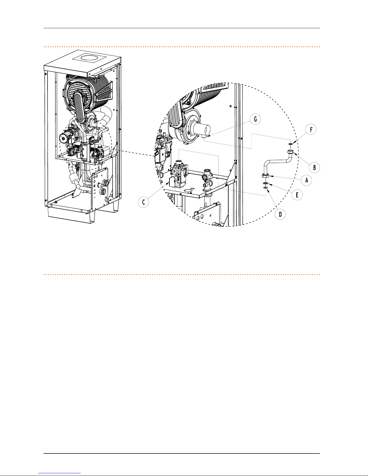
7 INITIAL ACTIVATION AND MAINTENANCE
Installation, user and maintenance manual – AY Condensing line, AY Series
57
Figure 7.3 – Gas type conversion
Details of gas changeover procedure.
LEGEND
A tube/valve connection nut
B tube/air-gas mixer connection nut
C gas valve
D gas nozzle
E gasket (large) on tube/valve tting
F gasket (small) on tube/air-gas mixer tting
G air-gas mixer
Page 58
8 ACCESSORIES
58
8 ACCESSORIES
This section contains a list of the accessories that are available for the installation and use of the appliance. To order these accessories,
contact Robur S.p.A. on +39.035.888111.
Table 8.1 – AVAILABLE ACCESSORIES
ACCESSORIES FOR INSTALLATION TECHNICIAN
Name Description Code Notes
ANTIVIBRATION MOUNT kit FOR BASE
Kit of 4 non-adjustable anti-vibration feet
for installation on the beams of the base.
ONTV008
For multiple units ONLY. For the mount
positioning spacings, see the dimensional drawings.
PLANT ELECTRICAL PUMP
Centrifugal pump for the circulation of
water in the hydraulic plant
OPMP000 For cold and hot water
HYDRAULIC SEPARATOR
Separator for balancing hydraulic circuits; with automatic air vent, drain valve
and insulation.
OSPR000 Maximum water ow rate 15 m
3/h.
WATER/GLYCOL MIX
Glycol water solution (water/glycol mix
50+50) for hot/cold hydraulic systems.
OGLC007
10 liters tank (50%÷50%). Glycol water
solution for machine internal circuit.
CONDENSATE PUMP
Pump for the condensate obtained from
combustion products.
OPMP006 Handles up to 20 units.
Direct Digital Controller (DDC)
Provides remote control of one or more
units.
OCRM007
No. 1 DDC per a maximum of 16 units in
the same installation. NB: with multiple
units, the DDC is standard supply.
RB100
Controller for handling sliding temperatures and remote ACS production.
ODSP001
Can be used in combination with the
DDC.
WISE (Web Invisible Service Employee)
Communications system for remote
handling, control and supervision of
installation.
ODSP000
Can be used in combination with the
DDC. The WISE unit has an integral antenna; 1 RS232 serial cable; 1 cable with
telephone jack; 1 CD-ROM.
Robur “NETBUS” CAN BUS CABLE
Cable for data communication networks:
for network connection between DDC
and appliance.
OCVO008
Maximum length: 450 m (for details, see
the electrical connections section).
List of appliance accessories.
Page 59
9 OPERATING CODES/TROUBLESHOOTING
Installation, user and maintenance manual – AY Condensing line, AY Series
59
9 OPERATING CODES/TROUBLESHOOTING
9.1 OVERVIEW AND OPERATING CODES/TROUBLESHOOTING
If, during the operation of the appliance, the display of the controller of the appliance (or also of the display of the Direct Digital
Controller, if connected) signals an operating code, it is necessary to:
▶
make a note of the indications shown on the display;
▶
consult the (specic) list of machine operating codes.
For the operating codes generated by the controller of the appliance, refer to Table 9.1→59. If the appliance is connected
to a DDC, a list of the operating codes generated by the DDC is provided in the DDC's manual (see "installation technician
manual - manual 1").
▶
carry out the instructions contained in it scrupulously (contact your Authorised Robur Technical Assistance Centre when instructed to do so).
If, after performing these operations, the appliance does not start, rst carry out the following simple checks:
▶
ensure that the external disconnecting switch tted by the electrical installation technician on a suitable panel (see Section
6→32) is set to ON;
▶
check that the consent switches (see Paragraph 6.3→39) or the DDC (if connected and in controller mode) are set for operation
of the appliance;
▶
check that the gas supply valve is open;
▶
determine that no further indications are given on the display.
At this point, if the appliance still does not start:
▶
refrain from proceeding by trial and error; instead request the direct assistance of an authorised Robur Technical Assistance Centre (TAC), informing it of the Machine Code that has arisen;
▶
disconnect the appliance from the gas and electricity supply, cutting o the gas supply by means of the appropriate tap and
electrical power via the external master power switch. Wait for the TAC sta to arrive.
For how to reset the machine operating code with the on-board controller, refer to Paragraph 4.3→15.
We list below the operating codes generated by the appliance's controller (rmware version 3.106). The following codes can also be
displayed by the DDC, if connected.
Table 9.1 – TABLE OF OPERATING CODES generated by the electronic board (rmware version 3.106)
CODES DESCRIPTION TRIP CONDITIONS RESET METHOD
E 100 FLAME RESET FAULTY The ame control unit reset circuit is faulty. Contact authorised Technical Assistance.
E 101 LIMIT THERMOSTAT
The limit thermostat is open. This only happens
if the ame controller is on and the gas solenoid
valve is excited (the thermostat is connected in
series with the solenoid valve power supply).
Contact authorised Technical Assistance.
u 102
FUMES THERMOSTAT AND/
OR INTERNAL EXCHANGER
THERMOSTAT
The fumes thermostat and/or the internal exchanger thermostat are interrupted.
Contact authorised Technical Assistance.
E 102
FUMES THERMOSTAT AND/
OR INTERNAL EXCHANGER
THERMOSTAT
"u 102" persistent for 1 hour. Contact authorised Technical Assistance.
E 103
HEATING CONTROLLER NOT
PRESENT
The auxiliary controller (S70) is not present. Contact authorised Technical Assistance.
E 105 HIGH AMBIENT TEMPERATURE
The ambient temperature is HIGH. This only happens when the appliance is operating.
Automatic (on termination of originating event).
E 106 LOW AMBIENT TEMPERATURE
The ambient temperature is LOW. This only happens when the appliance is operating.
Automatic (on termination of originating event).
u 107
WATER PRESSURE SWITCH (HOT
ONLY CIRCUIT)
The system water dierential pressure switch is
closed while the appliance is running in cooling
mode. This only happens when the appliance is
installed in a "hot/cold" system.
Automatic (on termination of originating event).
u 112 FLAME CONTROLLER FAULT The burner does not light.
Automatic when the ame controller attempts ignition again
(solenoid valve excited - maximum 4 attempts); or after 5 minutes
of persistence: in this case, ignition has failed and a new event has
occurred after "u112" was reset (run checks).
E 112
ARREST OF FLAME CONTROL
UNIT
Flame controller arrested - failure to ignite burner:
all possible attempts to ignite the burner have
failed.
Reset via the controller, menu 2, parameter 20 (or via DDC). If the
code persists, contact authorised TAC.
u 127
MACHINE INTERNAL CIRCUIT
WATER PRESSURE SWITCH
Lo stato del pressostato non corrisponde allo
stato del circolatore acqua del circuito interno
della macchina.
Automatico ed avviene se si ha corrispondenza di stato tra il circolatore e il pressostato dierenziale.
E 127
MACHINE INTERNAL CIRCUIT
WATER PRESSURE SWITCH
"u 127" persistent for 10 minutes.
Carry out appropriate checks. Reset via the controller, menu 2,
parameter 21 (or via DDC). If the code persists, contact authorised
TAC .
Page 60
9 OPERATING CODES/TROUBLESHOOTING
60
CODES DESCRIPTION TRIP CONDITIONS RESET METHOD
E 128
FLAME CONTROLLER ON AND
ARRESTED
The ame controller is arrested (E_12) but the gas
solenoid valve is excited. In this case the ame
controller is de-excited.
Reset via DDC (or via the controller, menu 2, parameter 20). If the
code persists, contact authorised TAC.
u 129
GAS SOLENOID VALVE WITHOUT
ELECTRICAL POWER
Gas solenoid valve is o for 5 seconds (with ame
controller on).
Automatic, when at least of the following conditions obtains (and
only if the "E 101" condition has not been forced): ame controller
o, or solenoid valve excited.
E 129
GAS SOLENOID VALVE WITHOUT
ELECTRICAL POWER
The gas solenoid valve has been o for more
than 10 minutes (with the ame controller on),
or "E 101" is keeping the ame controller on. Or
also in the case that, with the ame o (but ame
controller on) "E 101" obtains when generation of
"u/E" is enabled.
Reset via the controller, menu 2, parameter 21 (or via DDC). If the
code persists, contact authorised TAC.
E 135
DELIVERY WATER TEMPERATURE PROBE FAULT (MACHINE
CIRCUIT)
The delivery water probe on the internal circuit
(machine circuit) is faulty.
Contact authorised Technical Assistance.
u 136 MODULATING BLOWER FAULT The blower speed is out of range.
Reset occurs automatically 20 minutes after the operating code is
generated.
E 136 MODULATING BLOWER FAULT
u_36 code generated three times in 1 hour of
operation.
Contact authorised Technical Assistance.
u 175
SYSTEM CIRCUIT WATER PRESSURE SWITCH - Insucient
water ow
The system circuit water circulator is on and the
system circuit water dierential pressure switch
is open.
Automatico ed avviene se il circolatore si spegne, oppure se il pressostato dierenziale si chiude.
E 175
SYSTEM CIRCUIT WATER PRESSURE SWITCH - Insucient
water ow
Event u_175 has been generated 5 times since
the appliance was powered up, or code u_175 has
been active for 1 hour.
Carry out appropriate checks. Reset via the controller, menu 2,
parameter 21 (or via DDC). If the code persists, contact authorised
TAC .
E 176
OUTPUT WATER (SYSTEM) TEMPERATURE PROBE FAULT
Fault (interruption or short circuit) on outlet
system water temperature sensor.
Reset via the controller, menu 2, parameter 21 (or via DDC). If the
code persists, contact authorised TAC.
E 177
INPUT WATER (SYSTEM) TEMPERATURE PROBE FAULT
Fault (interruption or short circuit) on inlet system
water temperature sensor.
Reset via the controller, menu 2, parameter 21 (or via DDC). If the
code persists, contact authorised TAC.
u 178
DELIVERY WATER TEMPERATURE
(MACHINE CIRCUIT) HIGH
The water temperature on the internal circuit
(machine circuit) is too high.
Automatic (on termination of originating event).
u 179 DEFROST FUNCTION ACTIVATED
The temperature of the water has reached values
which could result in icing. In such cases, to prevent the appliance arresting, the defrost function
may activate only the system circuit circulator or
also the ame controller.
The defrost function is de-activated automatically when the ame
controller switches o and/or the circulator switches o. These
switch o when the water temperature has reached the values
required to ensure operation of he appliance. The defrost function
can also be de-activated manually via the controller, menu 4,
parameter 163.
u 80 INCOMPLETE PARAMETERS
Incomplete functional parameters (menus 3, 4
and 5).
The code persists until operating parameters are entered and
completed. Contact authorised TAC.
E 80 INVALID PARAMETERS
Invalid parameters (menu 6) or damage to parameter memory.
Reset occurs automatically when correct parameters are entered.
If the code persists, contact authorised TAC: if the memory is damaged, the controller must be replaced.
u 81; u 82
"BANK 1" AND "BANK 2" PARAMETERS: INVALID
Bank 1 data invalid - Bank 2 data invalid: in both
cases, one of the two parameter memory pages
contains invalid values.
Automatic (on termination of originating event).
E 81; E 82
"BANK 1" AND "BANK 2" PARAMETERS: INVALID
Bank 1 data invalid - Bank 2 data invalid: the program has failed to copy the data from the correct
page to the other page.
Contact authorised Technical Assistance.
E 84
FAULTY TRANSFORMER CONNECTION OR 24 V AC FUSES
Danneggiamento dei 2 fusibili di ingresso 240-24 Vac oppure interruzione del lo centrale
dell’alimentazione 24-0-24 Vac verso la scheda
Check fuses and 24-0-24 V AC electrical power connections on the
controller. Reset via the controller, menu 2, parameter 21 (or via
DDC). If the code persists or returns, contact authorised TAC.
E 85
INCORRECT MODULE TYPES
(from menu 6)
The set module type (from menu 6) does not correspond to the one managed by the controller.
Contact authorised Technical Assistance.
E 86; E 87; E 88
; E 89
MEMORY TEST UNSUCCESSFUL Processor error. Contact authorised Technical Assistance.
E 90
AMBIENT TEMPERATURE SENSOR DEFECTIVE
Interruption or short circuit of ambient temperature sensor.
Contact authorised Technical Assistance.
E 91 CONTROLLER DEFECTIVE
Numero seriale di scheda assente e/o codice di
versione hardware assente e/o chiave di criptazione assente o errata; oppure i dati di calibrazione
sono assenti o inconsistenti.
Contact authorised Technical Assistance.
Page 61

Page 62

Page 63

Page 64
Robur mission
Robur Spa
tecnologie avanzate
per la climatizzazione
Via Parigi 4/6
24040 Verdellino/Zingonia (Bg) Italy
T +39 035 888111∅F +39 035 884165
www.robur.it [email protected]
Robur is dedicated to dynamic progression
in research, development and promotion
of safe, environmentally-friendly, energy-eciency products,
through the commitment and caring
of its employees and partners.
Revisione: J Codice: D-LBR531 14 MCM SDC 007 10/03/2014
 Loading...