


SUMMARY OF CONTENTS
SECTION 1 GENERAL WARNINGS...........................................................................2
1.1 GENERAL INFORMATION.............................................................................3
SECTION 2 QUICK GUIDE FOR THE USER..............................................................7
2.1 GENERAL CHARACTERISTICS OF THE DIRECT DIGITAL CONTROLLER............7
2.2 MAIN SCREEN................................................................................................................ 8
2.3 USING THE
ENCODER..............................................................................10
2.4 COOLING/HEATING SERVICE CONTROL MENU........................................................11
2.5 BASE AND SEPARABLE DHW SERVICE CONTROL MENU
................................15
2.6 ALERTS MENU
............................................................................................16
2.7 ERROR RESET
............................................................................................17
2.8 FLAME CONTROL UNIT RESET
.....................................................................18
SECTION 3 FUNCTIONS OF THE DIRECT DIGITAL CONTROLLER.......................19
3.1 MAIN MENU................................................................................................19
3.2 FUNCTIONAL DATA
....................................................................................20
3.3 UNITS MANAGEMENT
..................................................................................27
3.4 USER SETTINGS
.........................................................................................31
SECTION 4 INSTALLATION.......................................................................................52
4.1 CONNECTING THE DIRECT DIGITAL CONTROLLER ........................................52
4.3 DESCRIPTION OF THE REGULATION WATER TEMPERATURE ALGORITHM AND
OF THE RELATIVE PARAMETERS
.................................................................57
4.4 SYSTEM INSTALLATION
..............................................................................66
4.5 INSTRUCTIONS FOR DDC-PLANT CONFIGURATION................................................124
4.6 MANAGEMENT AND DISPLAY OF WARNINGS AND ANOMALIES
......................146
SECTION 5 GENERAL INDEX...................................................................................156
Read the warnings contained in this manual carefully; they give important information regarding safe
installation, operation and maintenance: keep this manual safe for all further consultation.
The manufacturer may not be held responsible for any damage arising from improper, incorrect or
unreasonable use of the appliance.
NOTE

Direct Digital Controller
2 Direct Digital Controller fw 4.013 – Ed. 01/2013
1 GENERAL WARNINGS
This manual is an integral and essential part of the product and must be delivered to the end user.
The installation of the Direct Digital Controller must be carried out by professionally qualified
personnel, in compliance with current regulations and according to the manufacturer’s instructions, as
incorrect installation may cause damage to persons, animals or things (or directly to the component), for which
the manufacturer cannot be held responsible.
“Professionally qualified personnel” is defined as those possessing specific technical competence in the sector
of electrical systems.
This device must be used only for the purposes for which it has been expressly designed. Any other use must
be considered inappropriate and therefore dangerous.
The manufacturer is exempt from any contractual or extra-contractual responsibility for damage caused by
errors of installation, use and in any case the non-observance of the instructions supplied by the manufacturer
itself.
In the event of failure and/or poor operation of the Direct Digital Controller, do not attempt to repair it under
any circumstances; any repair must be carried out solely by a ROBUR Technical Assistance Centre, using
only original replacement parts.
The non-observance of the foregoing warnings may compromise the safety of the device.
It is not possible to install the Direct Digital Controller and the GA – GAHP and Prontoclima series of gas
absorption units correctly without consulting the Installation Manual included with the UNIT and the
Installation and Programming Instructions which follow.

Direct Digital Controller
Direct Digital Controller fw 4.013 – Ed. 01/2013 3
1.1 GENERAL INFORMATION
The Direct Digital Controller is a device that is applicable as a
panel, and which is able to show, on a backlit graphical LCD
display of 128x64 pixels, all the status, operating and error
conditions of each individual unit to which it is linked. The DDC
(Direct Digital Controller) controls water thermostating by
controlling the switch-on and switch-off of the units connected to it.
The Digital Panel can support and manage up to 32 modules (16
for heating and 16 for cooling) where module refers to the ability of
a machine to produce cooled or hot water;
therefore the ACF 60-
00 comprises a module for the production of chilled water, and the
AY 00-120 and GAHP-A each comprise a module for the
production of hot water; on the other hand, the GAHP-AR and the
GAHP-GS/WS comprise two modules, one for the production of
chilled water, the other for hot water (see table below).
The Direct Digital Controller, on the other hand, is able to manage
a single prontoclima heater/heater-chiller.
The Direct Digital Controller is, in addition, able to manage several
plant configurations for the production of hot and/or chilled water,
in particular:
1. 1 plant for the production of chilled water (cold plant). For example it is possible to connect up to a
maximum of 16 ACF 60-00 which correspond to a maximum of 16 chilling modules; OR:
2. 1 plant for the production of hot water (hot plant). For example it is possible to connect up to a maximum
of 16 GAHP-A or ACF 00-120 which correspond to a maximum of 16 heating modules; OR:
3. 2 independent plants, one to product chilled water, the other to produce hot water (4-line configuration)
able to run simultaneously (one cold plant and one hot plant, independent). It is therefore possible to
manage both plants described in points 1 and 2, for a maximum of 16 modules for heating; for example,
this is useful for installations with AHU fitted with a post-heating exchanger which works at the same time
as the cooling OR:
4. 1 plant for alternate production (summer/winter) of hot or chilled water (2-line hot-cold plant). This is a
two-line plant that, for example, in the winter serves the heating network and in the summer serves the
cooling network. For example it is possible to connect up to a maximum of 16 GAHP-AR or AYF 60-119/2
which correspond to a maximum of 16 heating modules for chilling and 16 modules for heating.
To create high output plants it is also possible to connect two or three DDCs together in order to control up to
64 or 96 modules (up to 32 units may be linked to each DDC).

Direct Digital Controller
4 Direct Digital Controller fw 4.013 – Ed. 01/2013
The Direct Digital Controller can manage modules of the ACF60 and AY00-119 type equipped with S61 and
S70 electronic boards respectively.
- GAHP-A = 1 “hot” module
- GAHP-AR = 2 modules (1 “cold” + 1 “hot”)
- GAHP-GS/WS = 2 modules (1 “cold” + 1 “hot”)
- GA HR = 1 "cold" module (the "hot" module of the recuperator is not managed by the control
system)
- ACF 60-00 = 1 "cold" module
- AYF 60-119/2 = 2 modules (1 “cold” + 1 “hot”)
- AYF 60-119/4 = 2 modules (1 “cold” + 1 “hot”)
- AY 00-120 = 1 "hot" module
Domestic hot water (DHW) production plant control
The DDC is also capable of controlling a plant including the production of hot domestic water, by installing one
or more optional RB100 or RB200 devices (Robur Box).
Definitions
Generator: general term indicating machines for the production of hot and/or chilled water. In the text they are
also referred to as machines or units.
Robur generator: generator (heat pump, boiler or refrigerator) produced by Robur. All types of Robur
generator can be directly managed from the Robur Direct Digital Controller (DDC) using the CANBus
communication bus.
Third party generator: generator (usually a boiler or refrigerator) not produce d by Robur, which cannot be
directly managed from the DDC via the CANBus and thus requires an additional interface device (Robur Box
RB200).
Network ID: unique identification number identifying a Robur generator o n the CANBus BUS, a Direct Digital
Controller (DDC), the valve service of an RB100 device, or each of the services provided by an RB200. It acts
as an address for the data communication network; it must be set to a different value for each generator, DDC
or RB100/RB200 device present. For RB200 devices a base network ID is set, then the system automatically
assigns from this a network ID for each configured service.
In the documentation it is also referred to as a CAN ID or, when referred to Robur generators, unit ID or
machine ID.
Base plant part: this term refers to the portion of the plant including all generators, excluding those which can
be hydraulically separated via a specific three-way valve.
Separable plant part: this term refers to the part of the plant which can be hydraulically separately from the
base plant part and run independently to provide a type of service for Domestic Hot Water (DHW).
This part of the system can be in two distinct states, on the basis of the position of the hydraulic separation
motorised valve:
• Separate: in this status, the generators from the separable part of the plant are managed together with
those of the base plant, in order to satisfy the request for the separable DHW service.
• Included: in this state the generators from the separable part of the plant are managed together with those
of the base part, to satisfy heating and/or base DHW services; in particular the generators are made
available if at least the heating request is active; in the presence of only the base DHW request, the
generators on the separable part of the plant are not used.
Separate plant part: variant of the separable part of the plant, which has no three-way separation valve; it is
therefore permanently sectioned off from the base plant part.
Base DHW service: domestic hot water service obtained with the base plant part.
Separable/separate DHW service: domestic hot water service obtained with the separable/separate plant
part.
Base group: set of generators on the base plant part.
NOTE

Direct Digital Controller
Direct Digital Controller fw 4.013 – Ed. 01/2013 5
Separable/separate group: set of generators on the separable/separate plant part.
Plant ID: identification number between 0 and 15, set by a specific parameter in the Robur generators to
indicate that they belong to a given plant, understood as the hydraulic circuit they are connected to. One or
more plant IDs (cold plant ID and/or hot plant ID) must be set on the RB200 device if this manages third party
generators.
NOTE
: The plant ID does not vary between the base and separable/separate plant parts. To indicate on
which part of the plant a Robur generator is found we use another parameter to be set on it (group to
which the unit belongs); to indicate on which part of the plant a Third Party generator managed via an
RB200 device is found, we use a parameter to be set on that device.
The RB100 and RB200 devices are used to interface requests for different types of services from one or more
external control systems with the DDC.
The inputs for the service requests available on each RB100 and RB200 interface device are the following:
Cooling service request: when this input signal is enabled, the equipment sends a request to the DDC so
that the latter can drive the switching on of the cold modules present on the plant and can manage them in
order to meet the request appropriately;
Heating service request: when this input signals is enabled, the equipment sends a request to the DDC so
that the latter can drive the switching on of the hot modules present on the plant and can manage them in
order to meet the request appropriately;
DHW0 and DHW1 service request: when one of these input signal is enabled, the equipment sends a
request to the DDC so that the latter can drive the switching on of the hot modules present on the plant and
can manage them in order to meet the domestic hot water request appropriately. In particular, each of these
inputs can be configured to make separable or base domestic water requests; it is also possible to enable both
inputs and therefore manage two DHW service requests at the same time.
The basic DHW service is normally used to provide a DHW service at circuit temperatures that are compatible
with Robur GAHP high efficiency heat pumps.
The separable or separate DHW service is normally used to provide a DHW service (complete or integrating
the base DHW service) which requires higher circuit temperatures, which are not compatible with the GAHP
heat pump units, therefore delivered by conventional heat generators (boilers) installed on the separable or
separate part of the plant.
RB100 and RB200 devices can also control the three-way valve used to hydraulically separate the separable
plant part from the base part.
Control of alternate hot/cold 2 line production plant with generation side or 4-line user side manifolds
Using the RB100 or RB200, the DDC is also able to control a three-way valve used to hydraulically commute
the plant for operation in either heating or cooling. The valve is useful in the following two cases:
• Plant with two line generation (for example in the case of GAHP-AR units) and distribution to four-line
services (for example underfloor heating and fan coil cooling).
• Plant with four line generation (use of only cold and only hot units mounted on separate manifolds) and
distribution to two-line services (for example heating and cooling both served by the sam e fan coils).
NOTE
: installation of only cold or only hot units on separate manifolds is not compulsory, but can be done
for specific reasons: for example, during the summer to allow the production of domestic hot water with
heat pumps and at the same time the production of cold water for cooling.
NOTE
: RB100 has only one valve control output, while RB200 has two outputs. Therefore, if you need to
manage both the separation valve and the cooling/heating commutation valve using an RB100 device, you
will need two; if you use the RB200 on the other hand, you will need only one device.
Direct Digital Controller
6 Direct Digital Controller fw 4.013 – Ed. 01/2013
Control of plant with third party boilers and/or chillers
Using the optional device RB200, the DDC can also control plants which include not only Robur units, but also
third party generators (boilers and/or chillers). The RB200 is used to interface these generators through
specific input and output signals; at this point, the DDC can control the system by switching on or off all the
available units, including third party ones.
NOTE
: these functions are not available on the RB100.
Control of other plant parts
Again thanks to the use of the optional RB200, the DDC can control the operation of different types of water
pump needed to implement different plant layouts, as well as acquire the temperature of the manifolds on the
different branches of the plant through temperature probes connected to the RB200. The use of manifold
probes makes the system configurations supported by the control system more flexible.
NOTE
: these functions are not available on the RB100.
Control system expandability using RB200 devices
When one or more RB200 devices are added to a system comprising DDCs and Robur heating or chilling
modules, the following rules apply:
1. On any system, also with maximum expansion (three DDCs, 48 heating modules and 48 chilling
modules) it is possible to add an RB200 device used fully, i.e.:
• with the heating, cooling and DHW requests enabled
• with all water pump, temperature probe and valve services enabled
• with both the third party generator service enabled; however it must be considered that every
third party generator occupies a heating or chilling module, which must therefore be included
in the calculation of the total number of modules
2. It is also possible to add up to seven more RB200 devices, used only to manage other third party
generators, again considering that every generator occupies a heating or chilling module, to be
included in the calculation of the total.
For further information concerning:
• Domestic hot water (DHW) production plant control
• Control of alternate hot/cold 2 line production plant with generation side or 4-line user side manifolds
• Control of plant with third party boilers and/or chillers
• Control of other plant parts
• Control system expandability using RB100 or RB200 devices
• Installation and use of RB100 or RB200 devices
Please consult the installation and user booklet of the RB 100 (code D-LBR468) and the RB 100
applications booklet (code D-LBR467), or RB 200 device (code D-LBR632) and the Applications Manual
(code D-LBR630), according to the type of device used.
NOTE

Direct Digital Controller
Direct Digital Controller fw 4.013 – Ed. 01/2013 7
2 QUICK GUIDE FOR THE USER
2.1 GENERAL CHARACTERISTICS OF THE DIRECT DIGITAL CONTROLLER
The Direct Digital Controller is a device that is applicable as a panel, and which is able to show, on a backlit
graphic LCD display of 128x64 pixels, all the status, operating and error conditions of each individual unit to
which it is linked. The DDC (Direct Digital Controller) controls water thermostating by controlling the switch-on
and switch-off of the units connected to it.
The following elements are present on the front of the panel:
Graphic display on which all the parameters necessary to control, program and configure the plants
managed by the DDC are shown (see detail A in Figure 1).
Selector knob (Encoder): the instrument with which it is possible to interact with the DDC. It allows the
operator to select options, set parameters etc. (see detail B in Figure 1).
RS 232 serial port for connecting the DDC to a PC (see detail C in Figure 1).
Figure 1 – FRONT VIEW OF DIRECT DIGITAL CONTROLLER.
A
B
C
KEY
A GRAPHIC DISPLAY
B SELECTOR KNOB (ENCODER)
C RS232 SERIAL PORT

Direct Digital Controller
8 Direct Digital Controller fw 4.013 – Ed. 01/2013
2.2 MAIN SCREEN
The Direct Digital Controller is equipped with a backlit LCD graphic display (128x64 pixels), able to display the
operating conditions of the plants and each individual unit to which it is linked.
The Direct Digital Controller’s display, during normal operation, allows the following parameters to be viewed:
Zone 1 The upper zone of the display which shows,
upon activation, the time, day and symbol of the unit of
measurement used to display inlet and outlet water
temperatures of each plant controlled.
In case services for the production of domestic hot
water are configured, the
icon is shown on top right
side; its selection/press permits to display the
operation parameters of the heating/cooling plant (
)
or of the domestic hot water plant (
).
Zone 2 This zone contains the symbol
, to indicate
that it refers to the plant operating parameters for the
production of chilled water. In the initial screen, upon
first activation of the DDC, the message “PLANT NOT
CONFIG” appears. During the operation, the water
inlet/outlet temperature values and the set point value
are shown (if the plant is ON).
appears on the
right, allowing access to the “Plant control” menu; A:
plant status ON/OFF; B: plant ID code (0-15).
Zone 3 This zone contains the symbol
, indicating
that it refers to the plant operating parameters for the
production of hot water as concerns the heating plant.
In the initial screen, upon first activation of the DDC,
the message “PLANT NOT CONFIG” appears.
During operation, inlet/outlet water temperatures of the
plant and the set point value are displayed (if the plant
is ON). The
icon on the right of the display allows
access to the “Plant control” menu;
A: ON/OFF status of plat; B: plant identification code
(0-15).
Zone 4 The last row displays a message that briefly
describes the icon on which the cursor is positioned.
The
icon allows access to the “error” menu; the
icon permits to access to the “Main menu”.
Zone 5 The symbol is shown to indicate that the zone contains the displaying of the operation
parameters of the hot water production plant for the base DHW service (production of domestic hot water
making use of the units on the base plant part with possibility of carrying out the production at the same
time with the heating service). During the operation, the water inlet/outlet temperature values and the set
point value are shown (if the plant is ON). appears on the right, allowing access to the “Base DHW
Plant control” menu; A: plant status ON/OFF; B: plant ID code (0-15).
If this kind of DHW service is not configured, caption “SERV. NOT CONFIGURED” is shown.
Zone 6 The symbol is shown to indicate that the zone contains the displaying of the operation
parameters of the hot water production plant for the separable DHW service (production of domestic hot
water making use of the units on the splitting plant part with alternating DHW/heating service or with DHW
service only). During the operation, the water inlet/outlet temperature values and the set point value are
shown (if the plant is ON).
appears on the right, allowing access to the “Separable DHW Plant
control” menu; A: plant status ON/OFF; B: plant ID code (0-15).
Figure 2 - EXAMPLES OF MAIN SCREEN
ZONE 1
ZONE 2
ZONE 3
ZONE 4
VISUALISATION OF DISPLAY UPON FIRST
ACTIVATION OF DIRECT DIGITAL CONTROLLER
ZONE 1
ZONE 2
ZONE 3
ZONE 4
VISUALIZATION OF OPERATING CONDITIONS
FOR “BASE DHW” AND “SEPARABLE DHW”
PLANTS
A B
VISUALIZATION OF OPERATING CONDITIONS
FOR 4 PIPE HEATING/COOLING PLANT
ZONE 1
ZONE 2
ZONE 3
ZONE 4
A B

Direct Digital Controller
Direct Digital Controller fw 4.013 – Ed. 01/2013 9
If this kind of DHW service is not configured, caption “SERV. NOT CONFIGURED” is shown.
The symbols used to represent the heating and/or cooling plant are the following:
Sun: represents the chilled water production plant (COOLING);
Snowflake: represents the hot water production plant (HEATING).
The main screen of the DDC, according to the type of plant configured, may appear as follows:
ONLY CONDITIONING PLANT
CONFIGURED
COOLING AND HEATING PLANTS
CONFIGURED FOR CONTEMPORARY
OPERATION ; DHW SYSTEM CONFIGURED
COOLING AND/OR HEATING PLANTS
CONFIGURED FOR ALTERNATING
OPERATION
PLANTS NOT CONFIGURED
ONLY HEATING PLANT CONFIGURED
HEATING AND DOMESTIC HOT WATER
PLANTS CONFIGURED
COOLING AND HEATING PLANTS
CONFIGURED FOR CONTEMPORARY
OPERATION (4 pipes)
COOLING AND HEATING PLANTS
CONFIGURED FOR ALTERNATING
OPERATION
ONLY DOMESTIC HOT
WATER PLANT CONFIGURED
NOTE

Direct Digital Controller
10 Direct Digital Controller fw 4.013 – Ed. 01/2013
If the set point is configured on inlet water, the inlet water set point is displayed below it (In).
In the event of errors occurring in the units of the plant(s), the following signals are given:
The
symbol flashes;
The display illumination flashes;
The device (if ON) emits an intermittent beep (see Paragraph 3.4.2.4 - “Alarm Beeper” on page 49).
1 – The DDC’s display reverts to the main screen after 30 minutes of inactivity (no operation of encoder).
2 – The backlighting of the display is switched off after 15 minutes of inactivity (see also Paragraph 3.4.2.5
- "Display Options", on page 50).
3 – If the encoder is turned or pressed while the display’s backlight is flashing, it stops flashing, and starts
flashing again after 25 seconds of inactivity, if the error conditions persist.
In all other screens the display’s illumination flashes.
2.3 USING THE ENCODER
The main user interface for management, programming and control of the DDC is the knob located on the
front of the Direct Digital Controller (the encoder).
The operations that may be performed with the encoder can be summarised as follows:
1 - Rotate the encoder in a clockwise or anticlockwise direction to position the cursor on the icons to be
selected on the display or to modify the value of a numerical field.
2 - Press the encoder to access the menu selected or to confirm the operation being carried out.
Each time instructions in this manual indicate that an icon, parameter etc. should be selected, it is necessary
to carry out the two operations described above.
NOTE
WARNING
ROTATING THE ENCODER
PRESSING THE ENCODER

Direct Digital Controller
Direct Digital Controller fw 4.013 – Ed. 01/2013 11
2.4 COOLING/HEATING SERVICE CONTROL MENU
Select the icon from the main screen, concerning the service to be controlled, to access the “Plant
control” menu. In this screen, on the basis of the configuration carried out, it is possible to select and manage
the buttons that switch on the cooling/heating plants.
The figure below shows how the “Plant control” menu screen appears to give an example of configuration.
Figure 3 – EXAMPLE OF COOLING/HEATING PLANT CONTROL SCREEN
Main ON/OFF switch of cooling/heating services. It permits to switch on/off the
controlled service(s) (cooling and heating or 2-pipe cooling/heating).
To sw itch on the service(s) , turn the knob and position the cursor on
and then
press the same. The button will appear thus
to indicate that the switch has been
closed (ON).
To sw itch off the service(s), turn the knob and position the cursor on
and then
press the same. The button will appear thus
to indicate that the switch has been
opened (OFF).
The symbol
indicates that the button has been disabled and that it is not possible
to select it. The switch will not affect the switching on of the plant.
Group ON/OFF switch. Use this button to switch on or off only the units that are directly
managed by the specific DDC. This button is enabled only for Multi DDC plants (i.e.
plants that are managed by several Direct Digital Controllers); the activation of those units
requires, however, that the main ON/OFF switch present only on the master DDC is
enabled.
To enable on the units controlled by the DDC, turn the knob to position the cursor on
, and press the knob. The button will appear thus to indicate that the switch
has been closed (ON).
To disable the units controlled by the DDC, turn the knob to position the cursor on
, and press the knob. The button will appear thus , indicating that the switch
has been opened (OFF).
The symbol
indicates that the button has been disabled and that it is not possible
to select it.
The switch does not affect the switching on of the units.
KEY:
A Main ON/OFF switch;
B Partial ON/OFF switch (enabled only on Multi
DDC systems)
C Button for enabling General water T timer;
D Button for enabling Partial water T timer (Multi
DDC plants only)
E Button for enabling chronothermostat;
F Heating-cooling switching button (only for the 2-
line heating/cooling systems)
G Exit menu.
A
B C D
E F G

Direct Digital Controller
12 Direct Digital Controller fw 4.013 – Ed. 01/2013
Button for enabling/disabling General water T timer. It enables/disables the use of the
switching-on timing for all the units.
To disable the general water T timer turn the knob and position the cursor on
then press the knob. The button will appear thus
, indicating that the water T timer
has been disabled and that the corresponding switch will be closed (ON status).
To enable the general water T timer turn the knob and position the cursor on
and
then press the knob. The button will appear thus
, indicating that the water T timer
has been enabled. The corresponding switch will be closed or opened according to
whether the time falls within a programmed timer cycle (see Paragraph 3.4.1.1.1.3 ,
programming the general water T timer).
The symbol
indicates that the button has been disabled and that it is not possible
to select it (switch with ON status).
Button for enabling/disabling Partial water T timer (button enabled only for Multi DDC
plants). This button allows the user to choose whether to program a switch-on time or not
only for the units managed by the individual DDC.
To disable the partial water T timer, turn the knob to position the cursor on
and
press the knob. The button will appear thus
, indicating that the partial water T
timer has been disabled and the corresponding switch will be closed (ON status). The
partial water T timer is in any case disabled if the General water T timer is disabled.
To enable the partial water T timer, turn the knob and position the cursor on
then
press the knob. The button will appear thus
, indicating that the Partial water T
timer has been enabled. The corresponding switch will be closed or opened according
to whether the time falls within a programmed Partial water T timer cycle (see
Paragraph 3.4.1.1.1.4 for the programming the Partial water T timer).
The symbol
indicates that the button has been disabled and that it is not possible
to select it (switch with ON status).
Chronothermostat activation/deactivation button;
This button is enabled in one of the following due cases and assumes different functions,
described below:
1- The room chronothermostat is active depending on the internal room probe (ambT
mode or equivalent, CUSTOM mode and "ChronT" active).
In this case:
• To disable the chronothermostat, turn the knob and position the cursor on
and then press the same. The button takes on the following aspect
indicating
that the chronothermostat has been deactivated and the corresponding switch is
closed (ON status), i.e. the system DOES NOT regulate the internal room
temperature).
• To enable the chronothermostat, turn the knob and position the cursor on
and then press the same. The button will appear thus , indicating that
the chronothermostat is enabled. The corresponding switch will be opened or
closed depending whether the room temperature satisfies the active room setpoint on the basis of chronothermostat programming. This means the system
regulates the internal room temperature on the basis of chronothermostat
programming (for further information see paragraph 3.4.1.2.3 “Chronothermostat”)
.

Direct Digital Controller
Direct Digital Controller fw 4.013 – Ed. 01/2013 13
2- The room thermostat is active based on the climatic curve and external temperature
probe (WCmp mode or equivalent equivalent, CUSTOM mode and “WCmp” function
active) and the climatic curve function is enabled in the user level menu “Enabling of
climatic curve” (see paragraph 3.4.1.1.1.2).
In this case, by pressing the knob repeatedly with the cursor positioned on the
chronothermostat activation/deactivation button, the symbol assumes the different
aspects in sequence to which the following modes correspond:
•
the room temperature set-point is that active on the bases of the
programming set on the chronothermostat.
•
o : the room temperature set-point is always T3 (maximum level of the
heating or cooling service)
•
the room temperature set-point is always T2 (average level of the heating or
cooling service)
•
o : the room temperature set-point is always T1 (minimum level of the
heating or cooling service)
NOTE: continuing to press the knob, the sequence is repeated.
Note that the climatic curve function remains active in all modes stated above; therefore in
this case the system ALWAYS regulates the internal room temperature, based on the
climatic curve. The change affects only the choice of the value of the room temperature
set-point value.
If neither of the two cases stated above exists, the button takes on the
aspect to
indicate that it is disabled. The system does not regulate the internal room temperature.
COOLING/HEATING switch button (button present for 2 line hot/cold plants only);
To change to Cooling turn the knob to position the cursor on
then press the
knob. The button will appear thus
, indicating that the plant will be enabled for
cooling operation.
To change to Heating mode turn the knob to position the cursor on
then press
the knob. The button will appear thus
, indicating that the plant will be enabled for
heating operation.
Heating/cooling priority selection button for GAHP-GS/WS module (button only present
on 4-line hot/cold plants with units of the GAHP-GS/WS type);
To give priority to Cooling turn the knob and position the cursor on
then press
the knob. The button will appear thus
, indicating that priority will be given to
cooling operation for the GAHP-GS/WS units.
To give priority to Heating turn the knob to position the cursor on
then press the
knob. The button will appear thus
, indicating that priority will be given to heating
operation for the GAHP-GS/WS Units.
For further information on the use of this button, consult the operation and maintenance
manual of the GAHP-GS/WS unit.
According to the configuration carried out, some of the buttons may be disabled. (status always ON). For
further details, consult Paragraph "On/off command configuration" on page 103.
NOTE

Direct Digital Controller
14 Direct Digital Controller fw 4.013 – Ed. 01/2013
As concerns the heating service, the switching off does not necessarily involve the switching off of the units.
In fact, if also one or more DHW production services are configured, the units can start to meet the DHW
requests. In order to ensure the real switching off of the plant, switch off also the DHW service(s), as
indicated in paragraph 2.5 “BASE AND SEPARABLE DHW SERVICE CONTROL MENU” on page 15.
NOTE

Direct Digital Controller
Direct Digital Controller fw 4.013 – Ed. 01/2013 15
2.5 BASE AND SEPARABLE DHW SERVICE CONTROL MENU
To access the “DHW Plant control” menu, follow the indications given below:
1 - Select the
icon from the initial screen and press the knob to gain access to the screen displaying the
base and separable DHW service operation parameters.
2 - Select the symbol positioned above to gain access to “Base DHW control” menu (see “Zone 5”
Figure 2 on page 6).
3 - Select the
symbol positioned below to gain access to “Separable DHW control” menu (see “Zone
6” Figure 2 on page 6).
4 - In both cases (“Base DHW control” and “Separable DHW control”) the screen shown in Figure 4 will be
displayed on the screen.
5 - The switching on of the Units of which use is made to produce domestic hot water requires also a request
coming from the RB100 or RB200; the button in position ON is not sufficient by itself to switch on the units
of the DHW group. The base or separable DHW services each require a specific request; for more
information please consult the installation and use booklet of the RB 100 (code D-LBR468) and the RB
100 applications booklet (code D-LBR467), or the installation and use booklet of the RB 200 (code DLBR632) and the applications manual (code D-LBR630), according to the type of device used.
Figure 4 – EXAMPLE OF BASE OR SEPARABLE DHW SERVICE CONTROL SCREEN
Base or separable DHW service ON/OFF switch. Used to switch the corresponding
DHW service ON/OFF.
To sw itch on the plant, turn the knob and position the cursor on
then press the
knob. The button will appear thus
to indicate that the switch has been closed
(ON).
To disable the plant, turn the knob and position the cursor on
and then press the
same. The button will appear thus
to indicate that the switch has been opened
(OFF).
The
symbol indicates that the button cannot be selected. The switch does not
affect the switching on of the units. The “milled” icon is shown only on the Slave DDC
in case of Multi-DDC configuration, and the switching On/Off of the corresponding
DHW service can occur only on the Master DDC. The “button” on the Slave DDC
reflect the status of the Master DDC button.
Switching off the DHW service does not necessarily imply that the units are switched off. If also the heating
service is configured, the units may come on to satisfy this request. In order to ensure the real switching off
of the plant, switch off also the heating service, as indicated in paragraph 2.4 “COOLING/HEATING
SERVICE CONTROL MENU” on page 11.
A
KEY
A General Power Switch

Direct Digital Controller
16 Direct Digital Controller fw 4.013 – Ed. 01/2013
2.6 ALERTS MENU
This menu allows the user to visualise any anomalies in the units of the plant(s).
To access the alerts menu, select
from the main screen.
The figure below indicates the alerts menu screen.
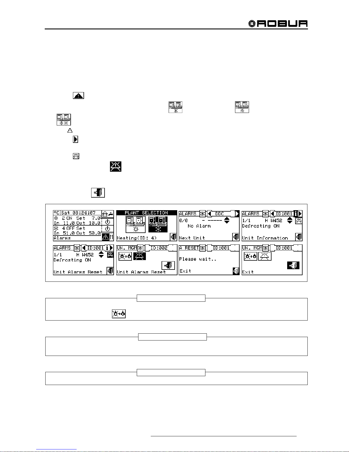
Figure 5 – EXAMPLE OF ALERTS MENU SCREEN
The alerts menu shows the events underway: it is possible to view the type of event (warning or error) for
each machine type.
Instructions to access the alerts menu:
1 - Select from the initial screen to gain access to the main menu.
2 - From the main menu, select
.
3 - Select the plant in which the events occurred:
for two-line cooling/heating plants, for hot water
production plants, or
for chilled water production plants. The symbol that appears next to a plant
icon indicates that anomalies are present in that plant.
4 - To search for the unit in which errors have occurred select
(detail “D” in Figure 5). If no error has
occurred, the message “No error” appears.
5 - Use the vertical scroll arrows
(detail “E” in Figure 5) to view all the events present on the unit.
The key allows the user to access the “MACHINE MANAGEMENT” menu in order to perform an error
reset, if necessary.
The button
i allows to access the “INFORMATION MENU” related with the selected unit.
KEY:
A Sequential number of events in progress for selected unit;
B System identification symbol; for cooling plant, for
heating plant;
C Indication of machine ID;
D Scroll arrows to change which unit’s events are displayed;
E Vertical scroll arrows: these allow the user to view the
events that have occurred on the unit;
F Indication of event code (Error: E, Warning: W);
G String describing the position in which the cursor is;
I Text describing event;
H String describing the action to be carried out to solve the
event that occurred;
M Anomaly regards:
C: conditioning module;
H: heating module;
B: electronic board.
N Access to the “unit information” of the selected unit;
O Access to the “unit alarms reset” of the selected unit
NOTE: the letters C and H will not be displayed for GAHP-
GS/WS
D
B C
D
I
H
A
G M
F
E
N
O
Direct Digital Controller
Direct Digital Controller fw 4.013 – Ed. 01/2013 17
2.7 ERROR RESET
This option allows the user to reset the anomalies present in the unit selected (with the exception of flame
control unit arrest).
To carry out an error reset, follow the instructions below:
1 - Select from the initial screen to access the alerts menu.
2 - Select the plant in which the events occurred:
for the cooling plant, for the heating plant, or
if the DDC is configured to manage a 2 line hot/cold plant.
The
symbol that appears next to a plant icon indicates that anomalies are present in that plant.
3 - Select
to view the screen that relates to the unit where the error has occurred.
4 - Select i to access to the “INFORMATION MENU” related to the selected unit.
5 - Select
to access the MACHINE MANAGEMENT menu directly.
6 - Position the cursor on
and press the knob to carry out an error reset.
7 - Wait for the operation to be performed. If the operation is successful, the message “OK” appears on the
display.
8 - To exit, select
.
An error reset does not reset the flame control unit. To reset the flame control unit is necessary to
move with the cursor on
and press the knob.
Error resets for which the message “Contact Technical Assistance” appears must only be carried
out by qualified personnel
It is not possible to reset errors on third party machines.
WARNING
NOTE
NOTE

Direct Digital Controller
18 Direct Digital Controller fw 4.013 – Ed. 01/2013
2.8 FLAME CONTROL UNIT RESET
This option allows the user to reset the flame control unit of the unit selected in the event of arrest of the
burner.
To carry out a reset of the flame control unit if the burner ceases to function, follow the instructions below:
1 - Select
from the initial screen to gain access to the main menu.
2 - From the main menu, select
to enter the Machine Management menu.
3 - Select the plant (
, or if the DDC is configured to manage only one hot/cold plant).
4 - Select the unit by using
or . The unit’s identification number is shown between the arrows.
5 - Select i to access to the “INFORMATION MENU” related to the selected unit.
6 - Position the cursor on
and press the knob to carry out a reset of the flame control unit.
7 - Wait for the operation to be performed. If the operation is successful, the message “OK” appears on the
display.
8 - To exit, select
.
By law it is possible to execute max. 5 flame reset attempts within a 15 min period. If you exceed this
number, the function is disabled and further attempts can only be executed directly on the affected unit, as
described in the relative manual.
The flame control unit can be reset also by accessing the “Errors” menu
from the initial screen (for more
details see paragraph 2.7 ERROR RESET on page 17).
The errors reset can also be done from this menu: position the cursor on
then press the knob
to carry out the reset of the trouble of the selected unit.
It is not possible to reset the flame control unit on third party machines.
NOTE
NOTE

Direct Digital Controller
Direct Digital Controller fw 4.013 – Ed. 01/2013 19
3 FUNCTIONS OF THE DIRECT DIGITAL CONTROLLER
3.1 MAIN MENU
To access the main menu from the initial screen, select
.
The main menu consists of 5 sections, as indicated in the figure on
the right:
Functional data.
Machine Management
User Settings
Installation (see Installation” Section)
Exit

Direct Digital Controller
20 Direct Digital Controller fw 4.013 – Ed. 01/2013
3.2 FUNCTIONAL DATA
The menu “Functional data” provides access to a scrolling menu that
allows the user to access all information regarding the plants and the
machines managed by the DDC. The options in this submenu are listed
below:
DDC information
Units information
Plants data
Service Centre
Alarms Log
Exit
3.2.1 DDC INFORMATION
By gaining access to two screens, some data concerning the DDC can
be displayed: Network ID assigned to the DDC, environmental
temperature (displayed if an environmental sensor is connected), power
supply voltage, serial ID. The second screen contains HW revision,
revision of Boot Loader FW, revision of application FW.
To access “DDC data”, follow the instructions below:
1 - Select from the initial screen to gain access to the main menu.
2 - Select
to gain access to the “Functional data” menu;
3 - Turn the knob to select the “DDC Information” menu, and press the
knob to access the menu.
4 - Select “1/2” to move to the second screen. To go back to the first
screen, select “2/2”.
5 - To exit, select
.
3.2.2 UNITS INFORMATION
By means of two or three screens some specific data concerning the
units can be displayed (machine type, serial ID of the unit board,
revisions of the HW and FW electronics) as well as other detailed data
concerning the module or the two modules that build up the unit (detailed
denomination of the module, its primary and secondary main codes,
separated by a “.”, then, the serial number).
To access to the “Units information” menu, follow the instructions
below:
1 - Select from the initial screen to gain access to the main menu.
2 - Select
to gain access to the “Functional data” menu;
3 - Turn the knob to select the “Units information” menu, then press the
knob to gain access.
4 - Select the unit making use of
or . The network ID of the
selected unit is indicated between the arrows; the first screen (“1/3”,
or “1/2”) containing the unit data is shown.
5 - Select “1/3” or “1/2” to move to the second screen, containing the data of the first module.
6 - If the unit consists of two modules, select “2/3” to move to the third screen, containing the data of the
second module.
Direct Digital Controller
Direct Digital Controller fw 4.013 – Ed. 01/2013 21
7 - Select “3/3” (or “2/2” in case of unit consisting of one module only) to go back to the first screen
8 - To exit, select
.
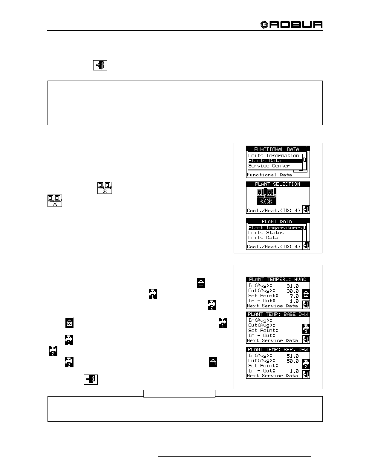
3.2.3 PLANTS
When the machines have been configured (see Section 4,
“INSTALLATION”), it is possible to view the functional data of the plants
managed. To enter the plants submenu, select “Plants” from the dropdown menu.
To view the operating data of the plants, select the desired icon. If two
plants have been configured, two icons will appear: one for the hot
plant, shown by the
icon, and one for the cold plant, shown by the
icon.
Select the plant for which the operating data is desired. A drop-down
menu will allow the user to select which data to view:
Plant temp.
Machine status
Machine data
Exit
3.2.3.1 Plant temperatures
The displaying concerns the temperature of water at inlet to/outlet from
the plant, the value of the set point temperature and the difference of
temperature between inlet and outlet of the cooling plant
or base
domestic hot water plant (base DHW)
(if configured) or separate
domestic hot water plant (separable/separated DHW)
(if
configured).
Select
to move to the screen concerning the base DHW plant (
will appear).
Select
to move to the screen concerning the separable DHW plant
(
will appear).
Select
to move to the screen concerning the cooling plant ( will
appear)
To exit, select
.
When viewing third party boilers or chillers managed via the Robur Box RB200, the first screen
shows the generic indication "Third Party Machine" and the serial ID, Hardware and Firmware
version of the RB200 device managing the boiler or chiller; the second screen shows a more
detailed description of the type of boiler or chiller (with or without water pump control, with or
without error reading) and the value of the corresponding configuration parameter set on the
RB200.
For a given temperature, if this is read by the manifold probe (managed via the RB200) rather than
by calculating the average of the machine probes, the indication between brackets will read
“(probe)” and not “(average)”.
NOTE

Direct Digital Controller
22 Direct Digital Controller fw 4.013 – Ed. 01/2013
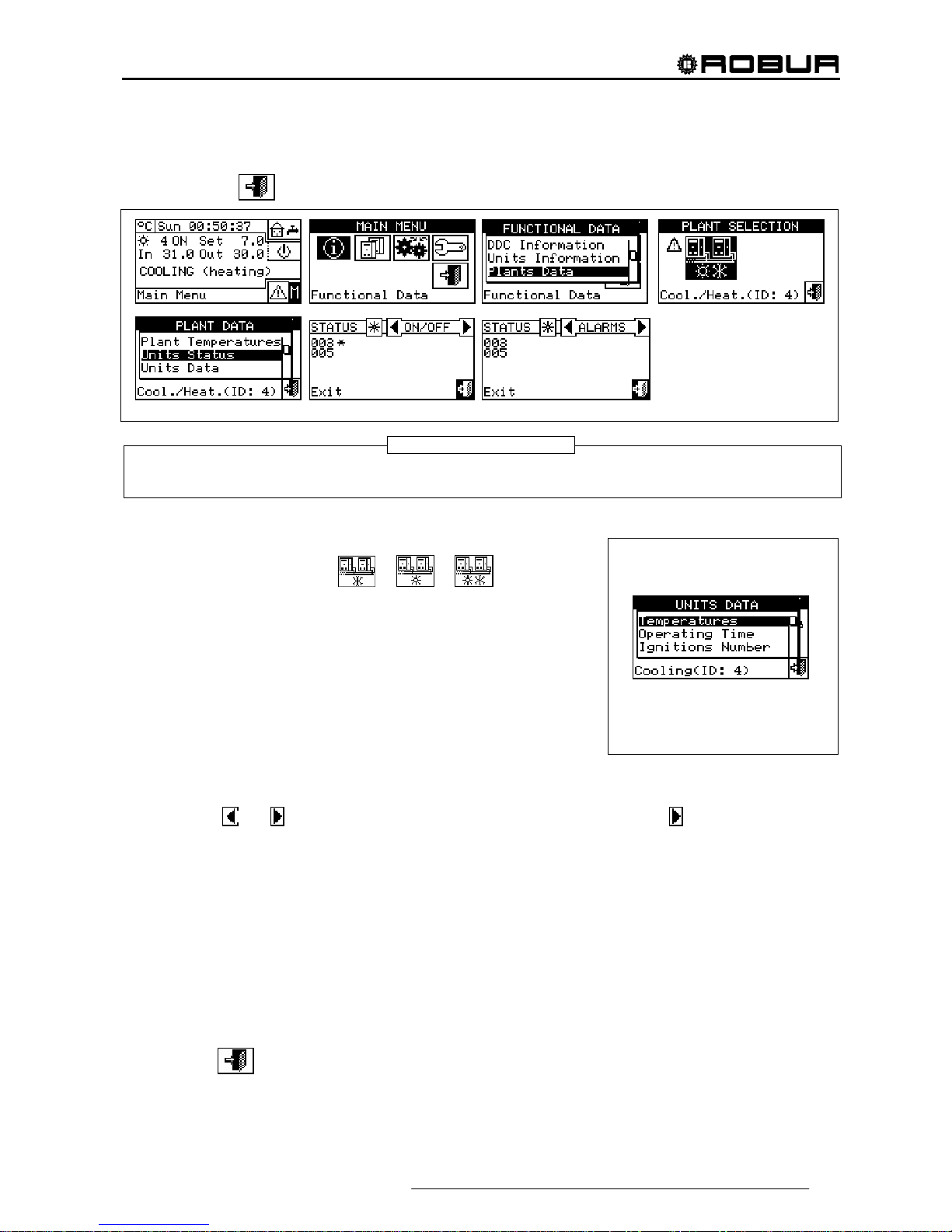
3.2.3.2 Machine status
The “Machine status” menu provides a complete overview of the units operating correctly and those where
errors have arisen. Each unit is identified by its network ID.
Two screens are present: “ACTIVATION” and “ERRORS”. Next to the machine ID, in the “ON” screen, the
following symbols appear:
1 - if the machine is on.
2 - If the unit is off, no symbol appears next to the machine ID.
3 -
if the machine has been excluded from the plant via the options
in the Units management menu.
4 -
if the unit is carrying out a Defrosting cycle. Option only for GAHP-
A and GAHP-AR units.
5 - if the unit is off because it has reached temperature or
thermostating limit values.
Select to visualise for which units errors or warnings have occurred. If an error has occurred in the machine,
the letter E will appear next to the unit’s ID.
In the “Error” screen next to the machine ID, the following symbols
appear:
1 -
if an error has occurred in the machine;
2 -
if a warning has occurred for the machine;
3 -
(“off-line”) if there are connection problems between the machine
and the DDC (the off-line may be due to various causes: the machine
is not powered, there are problems on the connection cable, the
machine board is malfunctioning and cannot communicate with the
DDC;
4 - If no error has occurred in the machine, no symbol will appear next to
the machine ID.
For two-line hot/cold plants, i.e. plants for the production of hot/chilled
water, the symbols
or apply.
Select
to view the screens relating to modules dedicated to the
production of chilled water (
is displayed).
Select
to view the screens relating to modules dedicated to the
production of hot water (
is displayed).
To access the menu, follow the instructions below:
1 - Select from the initial screen to gain access to the main menu.
2 - Select
to access the “Functional data” menu.
3 - Turn the knob to select the “Plants” menu, and press the knob to enter the menu.
4 - Select the plant for which to view the machine status:
for two-line cooling/heating plants, for
hot water production plants, or
for chilled water production plants. The symbol next to the plant
icon indicates an anomaly.
5 - Turn the knob to select the “Machine status” menu and press the knob to access the menu.
6 - Select
to move to the Errors screen: next to the identification number of each unit (ID = machine), the
letter E indicates that an error is present.
Direct Digital Controller
Direct Digital Controller fw 4.013 – Ed. 01/2013 23
7 - On both screens, a machine ID can be selected by turning the knob and, pressing it, access can be gained
directly to the “Machine information” menu.
8 - To exit, select
.
Warning: having carried out the machines configuration, each time it is switched on the DDC searches for
the configured units. Any units not found are considered to be “off-line”.
3.2.3.3 Machine data
In this menu the user may view typical machine operating data
according to the plant selected (
or or ).
The parameters that may be viewed are:
- Temperatures
- Operating time
- Ignitions Number
- Defrostings number
- Inversions Number
- Other data
Temperatures
An overview of all the operating temperatures of the machine selected. The machine’s ID is indicated between
the two arrows
and . To view the operating temperatures of another unit, select .
Which temperatures may be viewed depends on the type of machine selected (AY, ACF GAHP-GS/WS etc.).
A list of the temperatures that may be viewed on the screen is provided below.
1- In Unit inlet water temperature;
2- Out Unit outlet water temperature;
3- Ext External air temperature,
4- Cnd Condenser temperature;
5- Gen High generator temperature;
6- Eva Evaporator temperature;
7- TA1 TA2 Auxiliary probes.
8- Mix Air/gas mixture temperature
9- Fumi Temperature of the flue gas
10- GenF Temperature of the generator fins
To exit, select
.
NOTE
Direct Digital Controller
24 Direct Digital Controller fw 4.013 – Ed. 01/2013
It is not possible to view the operating temperatures of third party machines.
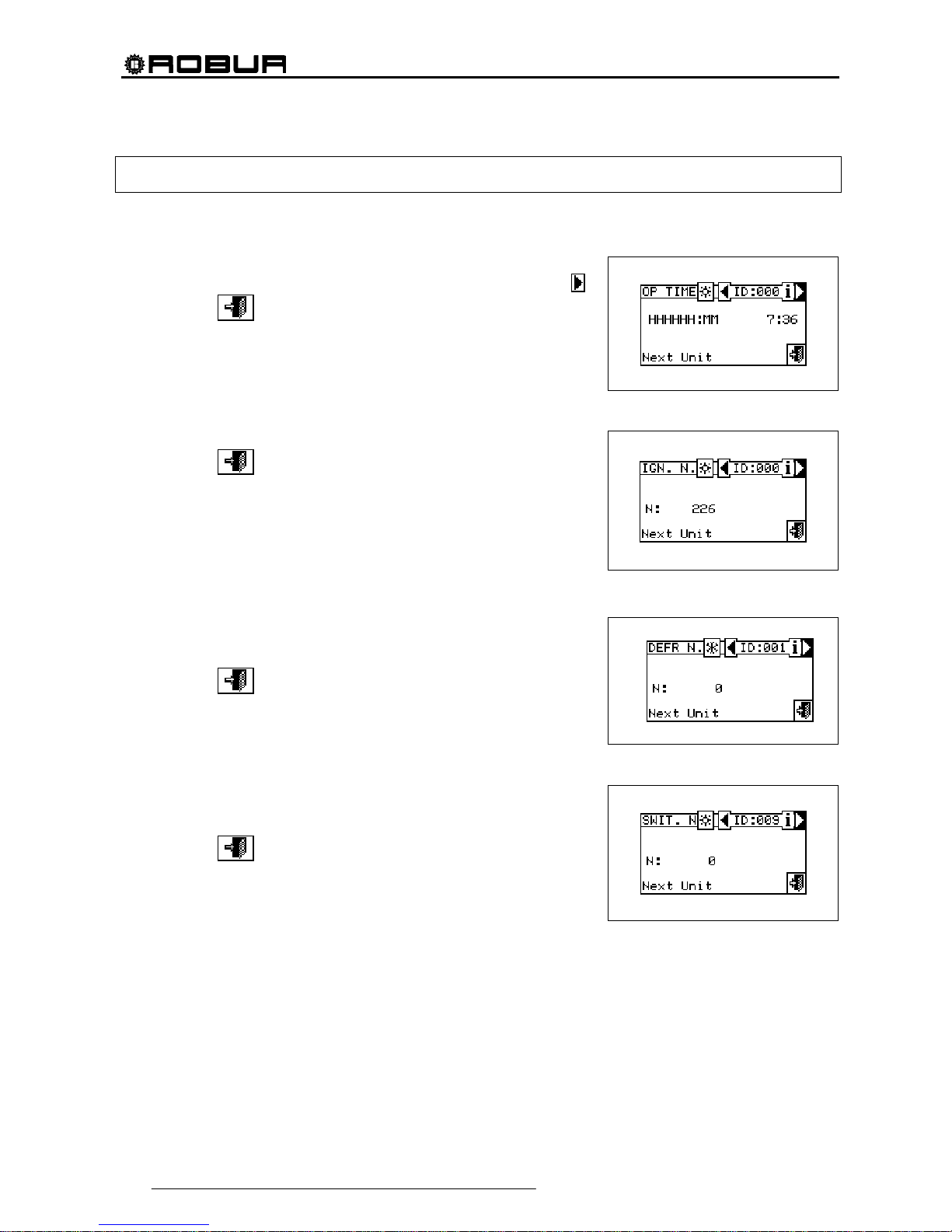
Operating Time
This screen shows the time that the machine has been operating in
hours and minutes. To view the operating time of another unit, select
.
To exit, select
.
Ignitions Number
This screen indicates the number of times the unit has been switched on.
To exit, select
.
Defrostings number
This screen indicates the number of defrosting cycles of the unit (GAHP
A-AR plants only).
To exit, select
.
Inversions number
Reports the number of times the unit has been inverted (GAHP-AR units
only).
To exit, select
.

Direct Digital Controller
Direct Digital Controller fw 4.013 – Ed. 01/2013 25
Other data
Indicates other data relative to the machine selected. To display the data
of another unit, select
to show the second screen 1/2; 2/2 to pass from
the second to the first screen.
To exit, select
.
It is not possible to view other data concerning third party
machines.
3.2.4 TECHNICAL ASSISTANCE
This screen gives information about the nearest Technical Assistance
Centre. See Paragraph 4.4.1.12 Technical assistance information
regarding the programming of technical assistance information.
To exit, select
.

Direct Digital Controller
26 Direct Digital Controller fw 4.013 – Ed. 01/2013
3.2.5 EVENT HISTORY
In this screen, it is possible to view all the parameters that characterise a warning or error event. All the events
are in chronological order from latest to earliest, and the times at which the event occurred and ended are
shown. For each event the following information is given, as shown in Figure 6: date, time, machine ID, error
or warning code, indication of which module (if required: “C” = Cooling, “H” = Heating) generated the event.
The ON indication regards the time the warning or error event arose, while the OFF indication regards the time
it ended. In addition, in the central area of the display there is a brief description of the type of event that
occurred.
All the events that occur are memorised in the Event history menu.
Figure 6 shows the Event history menu screen.
Figure 6 – EXAMPLE OF EVENT HISTORY MENU SCREEN
Instructions for accessing the event history
list follow:
1 - From the main menu, select
.
2 - Select
to access the “Functional data” menu.
3 - Turn the knob to select the “Event history” menu, and press the knob to access the menu.
4 - Position the cursor on the vertical scroll arrows (see detail “D” in Figure 6) to scroll through the events, from
latest to earliest.
5 - To exit, select
.
B
C
I
H
A
G
L
F
E
D
KEY:
A Date event detected;
B Time event detected;
C Indicator of number of events: the first number indicates the
chronological order of the event being viewed; the second
indicates the total number of events memorized by the DDC;
D Vertical scroll arrows. Use these to scroll through the events that
have occurred in the system in chronological order;
E Event status: ON refers to the moment that the event occurred;
OFF refers to the moment that it ended;
F Numerical code describing the type of event;
G Text describing the function highlighted by the cursor.
H Text describing the event.
I ID of machine or DDCs present where the event displayed
occurred;
L Origin of the anomaly:
C : cooling module;
H: heating module;
B: electronic board.
NOTE: the letters C and H are not displayed for GAHP-GS/WS units.
Direct Digital Controller
Direct Digital Controller fw 4.013 – Ed. 01/2013 27
3.3 UNITS MANAGEMENT
The menu allows the user to carry out certain operations upon the units controlled by the DDC.
Each machine has a screen associated with it in the “Units management” menu, which contains 5 icons that
allow the unit to be managed.
Flame control unit reset: this option allows the flame control unit of the selected machine to be
reset in the event of arrest.
Error reset: this option allows anomalies present in the selected unit to be reset (except in the
case of arrest of the flame control unit).
Machine exclusion: this option allows the selected machine to be excluded from the plant.
Modify set of parameters: this option allows the parameters set on the machine’s electronic
board to be modified. For a list of the parameters, consult the installation manual of the unit.
Default set of parameters: this option allows the default parameters memorised in the machine’s
electronic board to be reset.
Manual defrosting: The option allows the defrosting cycle to be carried out for the selected unit
(GAHP-a and GAHP-AR only).
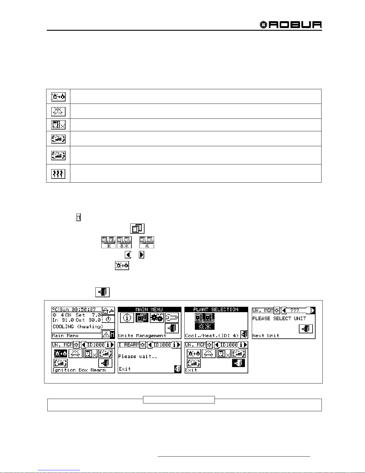
3.3.1 FLAME CONTROL UNIT RESET
To carry out a reset of the flame control unit if the burner ceases to function, follow the instructions below:
1 - Select
from the initial screen to gain access to the main menu.
2 - From the main menu, select
.
3 - Select the plant (
, or if the DDC is configured to manage only one hot/cold plant).
4 - Select the machine, using
or . The unit’s identification number is shown between the arrows.
5 - Position the cursor on
and press the knob to carry out a reset of the flame control unit.
6 - Wait for the operation to be performed. If the operation is successful, the message “OK” appears on the
display.
7 - To exit, select
.
It is not possible to reset the flame control unit on third party machines.
NOTE
Direct Digital Controller
28 Direct Digital Controller fw 4.013 – Ed. 01/2013
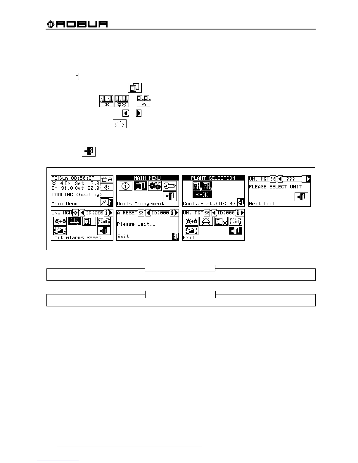
3.3.2 ERROR RESET
To carry out an error reset, follow the instructions below:
1 - Select
from the initial screen to gain access to the main menu.
2 - From the main menu, select
.
3 - Select the plant (
, or if the DDC is configured to manage only one hot/cold plant).
4 - Select the machine, using
or . The unit’s identification number is shown between the arrows.
5 - Position the cursor on
and press the knob to carry out an error reset.
6 - Wait for the operation to be performed. If the operation is successful, the message “OK” appears on the
display.
To exit, select
.
The reset does not perform a flame control unit reset.
It is not possible to reset errors on third party machines.
NOTE
NOTE
Direct Digital Controller
Direct Digital Controller fw 4.013 – Ed. 01/2013 29
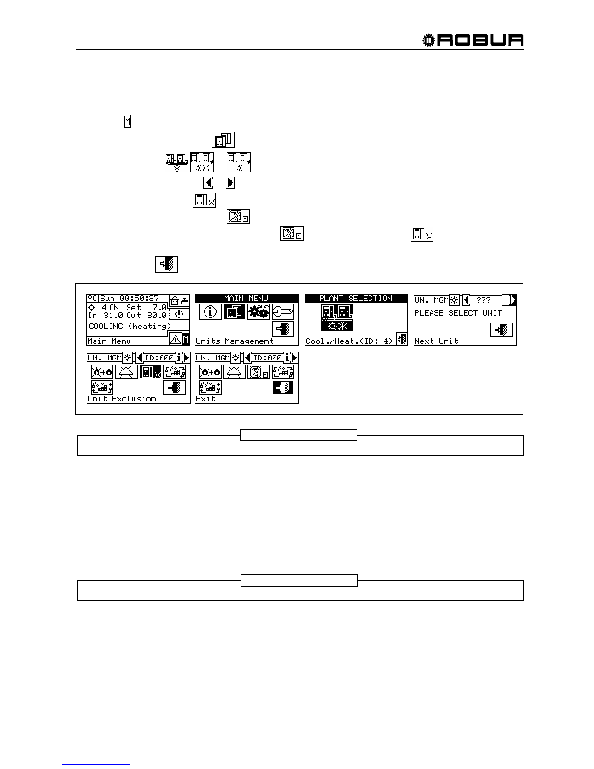
3.3.3 UNIT EXCLUSION
To exclude the unit from the plant, follow the instructions below:
1 - Select
from the initial screen to gain access to the main menu.
2 - From the main menu, select
.
3 - Select the plant (
, or if the DDC is configured to manage only one hot/cold plant).
4 - Select the machine, using
or . The unit’s identification number is shown between the arrows.
5 - Position the cursor on
and press the knob to exclude the machine from the plant. Wait for the
operation to be performed. The
symbol indicates that the machine is now excluded from the plant.
To include the unit in the plant again, select
and press the knob. The symbol indicates that
the machine is now excluded from the plant.
6 - To exit, select
.
When a machine is excluded, the DDC considers it unusable. In addition, any anomalies are not signalled.
3.3.4 EDIT SET PARAMETERS (Technical Assistance Centres only)
This option allows the modification of some parameters that are set on the machine’s built-in electronic boar d.
The Direct Digital Controller communicates with the machine’s electronic board and receives information
regarding the parameters set on it. Via the DDC, the operator may modify some of these parameters and
transmit them again to the machine’s built-in electronic board.
The option is protected by an installer password.
The figure below shows an example of a modification to the parameters, and the sequence of operations to
perform in relation to the screens shown on the display.
It is not possible to carry out the "modify set parameters" operation on third party machines.
NOTE
NOTE

Direct Digital Controller
30 Direct Digital Controller fw 4.013 – Ed. 01/2013
3.3.5 SET DEFAULT PARAMETERS (Technical Assistance Centres only)
The option allows the user to restore, via the DDC, the factory settings memorised on the built-in electronic
board of the machine.
The Direct Digital Controller communicates with the electronic board and receives information regarding the
default parameters (factory settings) set on it (warning: the default parameters are read-only, i.e. cannot be
modified). Via the DDC, the operator may modify some of these parameters and transmit them again to the
machine’s electronic board. The parameters transmitted are used by the board for operation of the unit but this
transmission will have no influence on the default settings memorised on board the machine.
The option is protected by an installer password.
It is not possible to carry out the "set default parameters" operation on third party machines.
NOTE
Direct Digital Controller
Direct Digital Controller fw 4.013 – Ed. 01/2013 31
3.4 USER SETTINGS
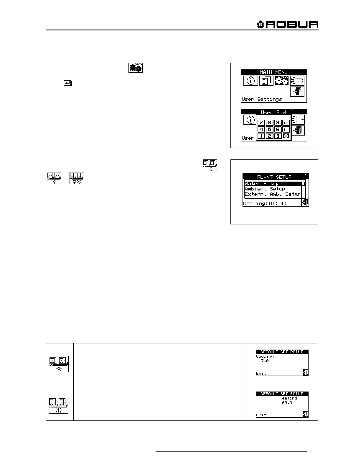
From the main menu, select . If requested, enter the user
password on the numerical keypad that appears on the screen and then
select
to confirm. If the wrong password is entered, the display
reverts to the main menu screen.
Accessing this menu allows the following parameters to be
consulted/set:
3.4.1 plants
3.4.2 PREFERENCES
3.4.3 Exit
3.4.1 PLANTS
PLANTS Select “Plants” from the dropdown menu. Select the
or
or plant in function of the type of configured plant. Access
is gained to a scroll menu containing the parameters that can be set:
3.4.1.1 Water Setup
3.4.1.2 Ambient Setup
3.4.1.3 External ambient setup
3.4.1.1 Water Setup
The following paragraphs describe the operating logic of the Direct Digital Controller to allow the operator to
set the water parameters correctly, such as set point temperature, differential, and number of steps.
3.4.1.1.1 Cooling/Heating
The options that may be set in this menu, for the cooling/heating services, are:
3.4.1.1.1.1 Default set point
3.4.1.1.1.2 Enabling of climatic curve
3.4.1.1.1.3 General water T timer
3.4.1.1.1.4 Partial water T timer
3.4.1.1.1.1. Default set point
This screen displays the water set point temperatures for cooling and/or heating operation according to the
type of plant configured.
Plant for production of chilled water. The set point represents the desired
temperature for water leaving the machine if, in the System installation,
thermostating has been set on the outlet water; if the opposite applies, the
temperature set point represents the desired temperature for the machine’s inlet
water.
Plant for production of hot water. The set point represents the desired temperature
for water leaving the machine if, in the System installation, thermostating has been
set on the outlet water; if the opposite applies, the temperature set point represents
the desired temperature for the machine’s inlet water.

Direct Digital Controller
32 Direct Digital Controller fw 4.013 – Ed. 01/2013
Plant for alternate production of hot or chilled water.
Cooling set point: water temperature when the plant produces chilled water.
Heating set point: water temperature when the plant produces hot water.
The two set points described above may refer to outlet or inlet water, according to
the settings, which may be different from one another, configured in the installer
menu.
Configuring set point temperature.
In order to set the set point temperature for the heating and/or cooling services, follow the instructions below:
1 - Select
from the initial screen to gain access to the main menu.
2 - Select
to access the “User settings” menu.
3 - If requested, enter the user password on the numerical keypad that appears on the display.
4 - Select “Plants” from the drop-down menu.
5 - Select the plant for which the set point temperature is to be set:
for two-line cooling/heating plants,
for hot water production plants, or for chilled water production plants.
6 - Select “Water setup” from the drop-down menu.
7 - Select “Cooling” or “Heating” from the drop-down menu
8 - Select “Default set point” from the drop-down menu.
9 - Position the cursor on the temperature value to modify: for cold-only plants
, only the value of the
set point temperature in cooling mode appears (Cooling). For hot-only plants
, only the value of the
set point temperature in heating mode appears (Heating).For two-line hot-cold plants
, set point
temperatures for both heating and cooling mode appear (Cooling and Heating).
10 - Press the knob to allow the change of the selected value.
11 - Turn the knob to modify the value.
12 - Press the knob to confirm the set value.
13 - To exit, select
.
The default set point is used when the general water T timer cycles are disabled. Otherwise the set point
used at any given moment is that defined in the active water T timer cycle (see Paragraph 3.4.1.1.1.3 "General water T timer" ).
NOTE

Direct Digital Controller
Direct Digital Controller fw 4.013 – Ed. 01/2013 33
3.4.1.1.1.2. Enabling of climatic curve
To enable the climatic curves for the heating and/or cooling services, follow the instructions given:
1 - Select
from the initial screen to gain access to the main menu.
2 - Select
to access the “User settings” menu.
3 - If requested, enter the user password on the numerical keypad that appears on the display.
4 - Select “Plants” from the drop-down menu.
5 - Select the plant for which the climatic curve is to be enabled:
for two-line cooling/heating plants,
for hot water production plants, or for chilled water production plants.
6 - Select “Water setup” from the drop-down menu.
7 - Select “Cooling” or “Heating” or "Cool./Heat" from the drop-down menu.
8 - Select "Enab. Clim. Curve" from the drop down menu. Turn the knob and select the desired item.
9 - Turn the knob and select the desired item. Press the knob to enable/disable the climatic curve. The
symbol indicates that the climatic curve is enabled; the symbol indicates that the climatic curve has
been disabled.
10 - To exit, select
.
The climatic curve can only be enabled if an operating mode has been chosen that allows it (see paragraph
“On/off command configuration” on page 103).
If the climatic curve is enabled, the water set point is variable and is calculated by the DDC according to the
set climatic curve, the external temperature and the requested room temperature.
If the climatic curve is disabled, the corresponding default water set point will be used (see paragraph
3.4.1.1.1.1).
NOTE

Direct Digital Controller
34 Direct Digital Controller fw 4.013 – Ed. 01/2013
3.4.1.1.1.3. General water T timer
This option allows the user to manage the “General water T timer” operating mode of the plant as concerns
the heating and cooling services. It allows the user to select up to 4 plant activation time intervals, within which
it is possible to define a water set point temperature. Up to 4 daily water T timer cycles can be programmed, to
which it is possible to associate 4 different temperature levels. It is possible to enable/disable each water T
timer cycle programmed without cancelling it by operating on the
fields as described below. This
programming may be different for each of the seven days of the week and for the cooling and heating
services.
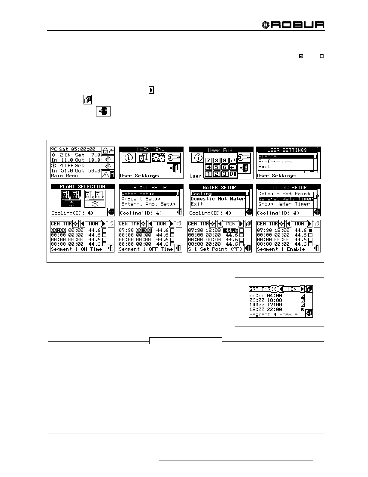
Programming general water T timer cycles
Figure 7 shows how the DDC’s display appears while the general water T timer cycles are programmed.
Figure 7 – PROGRAMMING SCREEN FOR GENERAL WATER T TIMER CYCLES
For plants managed by several Direct Digital Controllers, it is only possible to program the General water T
timer cycles from the DDC designated as the Master DDC.
In order to program the switching-on T timer cycles for a typical day, follow the instructions below:
1. Select
from the initial screen to gain access to the main menu.
2. Select
to access the “User settings” menu.
3. If requested, enter the user password on the numerical keypad that appears on the display.
4. Select “Plants” from the drop-down menu.
5. Select the plant for which the partial water T timer cycles are to be programmed:
for two-line
cooling/heating plants,
for the heating plant, for the cooling plant.
6. Select “Water setup” from the drop-down menu.
7. Select “Cooling” or “Heating” from the drop-down menu
8. Select “General Water Timer” from the drop-down menu.
9. Position the cursor on the activation time of the first water T timer cycle and press the knob. Turn the
knob to select the activation time of the first timer cycle and press the knob to confirm. The cursor moves
automatically to the deactivation time of the first timer cycle. Proceed in the same way to program the
deactivation time of the first timer cycle.
10. Set the water set-point temperature for the programmed timer cycle. Press the knob to modify the
temperature value once the cursor is positioned on the number. Turn the knob to modify the value. Press
the knob to confirm.
11. The cursor moves automatically to
for the activation of the timer cycle programmed. Press the knob to
enable the timer cycle. The symbol indicates that the timer cycle that has just been programmed has
KEY:
A Gene ral water T timer;
B T timer cycle switching –on time;
C Water T timer cycle switching-off time;
D Identification symbol of the system for which the water T timer
cycles are being programmed;
for the heating plant; for the
cooling plant. For two-line hot/cold systems it is a button that
allows the user to pass from programming one system to the
other;
E Day for which water T timer cycles are being programmed;
F Scroll arrows to change day;
G Button for copying previous day’s settings to current day;
H Checkbox for activation of programmed water T timer cycle;
I Set point temperature for the programmed period;
L Text describing the function highlighted by the cursor;
M Activation/deactivation times of water T timer cycles.
D
F
H
M
I
A
F
E
G
C
B
L
Direct Digital Controller
Direct Digital Controller fw 4.013 – Ed. 01/2013 35
been enabled. NOTE: a water T timer cycle may be disabled at any moment by pressing . The
symbol indicates that the water T timer cycle programmed has been disabled.
12. Proceed in the same way, repeating steps 9 – 10 - 11 for the programming of any further timer cycles
required.
13. Once the desired timer cycles have been programmed, it is possible to pass to the following day by
selecting the arrow at the top right
. The previous day’s program may be copied for the current day by
selecting
, or the water T timer cycles required for the new day may be programmed.
14. To exit, select
.
If a programming anomaly occurs, appropriate alert messages are displayed:
Water T timer cycle with zero (or “negative”) duration.
Water T timer cycle in conflict with another timer cycle.
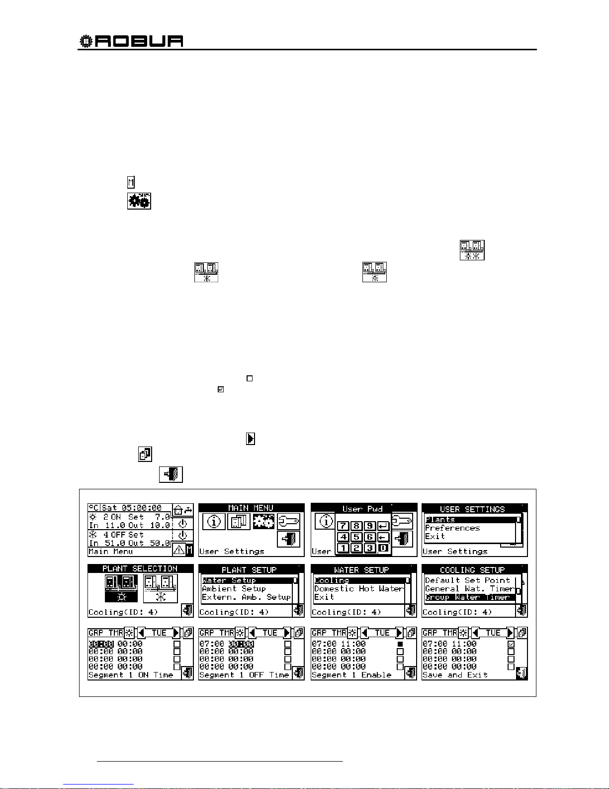
3.4.1.1.1.4. Partial water T timer
Partial water T timer This option may be programmed for Multi DDC
plants only, and allows the user to select up to 4 operating timer cycles
for each day of the week. This programming may be different for each of
the seven days of the week, and for the cooling and heating services.
The partial water T timers control only the machines directly managed by a specific DDC. Therefore,
according to the number of DDCs present in the plant, two situations may arise:
The plant is controlled by a single DDC. The DDC is defined as Master DDC by default and it is
possible to use ONLY the general water T timer.
The plant is controlled by more than one DDC (MASTER and SLAVE). In this case only one of the
DDCs installed is defined as the Master DDC. Via this DDC it is possible to program the general water T
timer to control the entire plant, and the partial water T timer to control the units that are managed
directly by the Master DDC. On the Slave DDCs it is possible to program the partial water T timer for the
purposes of controlling only the machines connected to the DDC in question. The group of machines
managed by any given DDC operates at the intersection between the general water T timer cycles and
partial water T timer cycles set on it. If, for example, a 0-10 general water T timer cycle has been set on
the Master DDC, and on a Slave DDC a 6-12 partial water T timer cycle, the units managed by the Slave
DDC may have ON status only between 6 and10.
WARNING
Direct Digital Controller
36 Direct Digital Controller fw 4.013 – Ed. 01/2013
Programming partial water T timer cycles
Programming of the partial water T timer cycles affects only plants managed by several Direct Digital
Controllers.
In this case, on the Master plant DDC it is possible to program the general water T timer cycles of the overall
plant and the partial water T timer cycles of all the units directly managed by the same Master DDC. On each
Slave DDC it is possible to program the partial water T timer cycles from that Slave DDC.
To program the water T timer cycles for a typical day, follow the instructions below.
1 - Select
from the initial screen to gain access to the main menu.
2 - Select
to access the “User settings” menu.
3 - If requested, enter the user password on the numerical keypad that appears on the display.
4 - Select “Plants” from the drop-down menu.
5 - Select the plant for which the partial water T timer cycles are to be programmed:
for two-line
cooling/heating plants,
for hot water production plants, or for chilled water production plants.
6 - Select “Water setup” from the drop-down menu.
7 - Select “Cooling” or “Heating” from the drop-down menu.
8 - Select “Group Water Timer” from the drop-down menu.
9 - Position the cursor on the activation time of the first water T timer cycle and press the knob. Turn the
knob to select the activation time of the first timer cycle and press the knob to confirm. The cursor moves
automatically to the deactivation time of the first timer cycle. Proceed in the same way to program the
deactivation time of the first timer cycle.
10 - The cursor moves automatically to
for the activation of the timer cycle programmed. Press the knob to
enable the timer cycle. The
symbol indicates that the timer cycle that has just been programmed has
been enabled.
11 - Proceed in the same way, repeating steps 1-3 for the programming of any further timer cycles required.
12 - Once the desired timer cycles have been programmed, it is possible to pass to the following day by
selecting the arrow at the top right
. The previous day’s program may be copied for the current day by
selecting
, or the water T timer cycles required for the new day may be programmed.
13 - To exit, select
.

Direct Digital Controller
Direct Digital Controller fw 4.013 – Ed. 01/2013 37
At any given moment, the set point used is the one set for the General water T timer cycle active at that
moment, or the default set point if general water T timer cycles are disabled.
It is not possible to use the General water T timer cycles at the same time as the climatic curve mode.
3.4.1.1.2 Domestic hot water
The options that may be set in this menu, for the domestic hot water production services, are:
3.4.1.1.2.1 Base plant water timer (for base DHW service)
3.4.1.1.2.2 Separable plant water timer (for separable DHW service)
3.4.1.1.2.1. Base plant water timer
This option permits to manage the “Base plant water timer” operation mode of the base service of domestic
hot water. It allows the user to select up to 4 plant activation time intervals, within which it is possible to define
a water set point temperature.
The water T timer cycles and the relevant set point are taken in consideration ONLY if, on the RB100 or
RB200 device (absolutely necessary for the domestic hot water control) the “Type of set point inlet for the
domestic hot water” parameter is set as “digital with set point on Digital Control Panel”.
For more information please consult the installation and user booklet of the RB 100 (code D-LBR468) and
the RB 100 applications booklet (code D-LBR467), or the installation and user booklet of the RB 200 device
(code D-LBR632) and the Applications Manual (code D-LBR630), according to the type of device used.
Up to 4 daily water T timer cycles can be programmed, to which it is possible to associate 4 different
temperature levels. It is possible to enable/disable each water T timer cycle programmed without cancelling it
by operating on the
fields as described below. This programming may be different for each of the seven
days of the week.
NOTE
NOTE

Direct Digital Controller
38 Direct Digital Controller fw 4.013 – Ed. 01/2013
Base plant timer programming
Figure 8 shows as the DDC display appears when programming the base plant water T timer cycles.
Figure 8 – SCREEN FOR THE PROGRAMMING OF THE BASE PLANT T TIMER CYCLES
In case of plants managed by several DDC, the programming of the water T timer cycles can be carried out
only by the DDC defined as Master.
In order to program the switching-on T timer cycles for a typical day, follow the instructions below:
1. Select
from the initial screen to gain access to the main menu.
2. Select
to access the “User settings” menu.
3. If requested, enter the user password on the numerical keypad that appears on the display.
4. Select “Plants” from the drop-down menu.
5. Select the plant for which the partial water T timer cycles are to be programmed:
for two-line
cooling/heating plants,
for hot water production plants, or for chilled water production plants.
6. Select “Water setup” from the drop-down menu.
7. Select “Domestic hot water” from the drop-down menu.
8. Select “Base plt wat timer” from the drop-down menu.
9. Position the cursor on the activation time of the first water T timer cycle and press the knob. Turn the
knob to select the activation time of the first timer cycle and press the knob to confirm. The cursor moves
automatically to the deactivation time of the first timer cycle. Proceed in the same way to program the
deactivation time of the first timer cycle.
10. Set the water set-point temperature for the programmed timer cycle. Press the knob to modify the
temperature value once the cursor is positioned on the number. Turn the knob to modify the value. Press
the knob to confirm.
11. The cursor moves automatically to
for the activation of the timer cycle programmed. Press the knob to
enable the timer cycle. The
symbol indicates that the timer cycle that has just been programmed has
been enabled. NOTE: a water T timer cycle may be disabled at any moment by pressing . The
symbol indicates that the water T timer cycle programmed has been disabled.
12. Proceed in the same way, repeating steps 9 – 10 - 11 for the programming of any further timer cycles
required.
13. Once the desired timer cycles have been programmed, it is possible to pass to the following day by
selecting the arrow at the top right
. The previous day’s program may be copied for the current day by
selecting
, or the water T timer cycles required for the new day may be programmed.
KEY:
A Programming of base DHW system timer cycles;
B T timer cycle switching –on time
C Water T timer cycle switching-off time
D Symbol identifying that the system for which the T timer cycles are
being programmed is the domestic hot water system
E Day for which water T timer cycles are being programmed
F Scroll arrows to change day
G Button for copying previous day’s settings to current day
H Checkbox for activation of programmed water T timer cycle
I Setpoint temperature for the programmed period
L Text describing the function highlighted by the cursor
M Activation/deactivation times of water T timer cycles
D F
H
M
I
A
F
E
G
C
B
L

Direct Digital Controller
Direct Digital Controller fw 4.013 – Ed. 01/2013 39
14. To exit, select .
If a programming anomaly occurs, appropriate alert messages are displayed:
Water T timer cycle with zero (or “negative”) duration.
Water T timer cycle in conflict with another timer cycle.
3.4.1.1.2.2. Separable plant water timer
This option permits to manage the “Separable plant water T timer cycles” operation mode of the separable
service for the production of domestic hot water . It allows the user to select up to 4 plant activation time
intervals, within which it is possible to define a water set point temperature.
The water T timer cycles and the relevant set point are taken in consideration ONLY if, on the RB100 or
RB200 device (absolutely necessary for the domestic hot water control) the “Type of set point inlet for the
domestic hot water” parameter is set as “digital with set point on Digital Control Panel”.
For more information please consult the installation and user booklet of the RB 100 (code D-LBR468) and
the RB 100 applications booklet (code D-LBR467), or the installation and user booklet of the RB 200 device
(code D-LBR632) and the Applications Manual (code D-LBR630), according to the type of device used.
Up to 4 daily water T timer cycles can be programmed, to which it is possible to associate 4 different
temperature levels. It is possible to enable/disable each water T timer cycle programmed without cancelling it
by operating on the
fields as described below. This programming may be different for each of the seven
days of the week.
NOTE
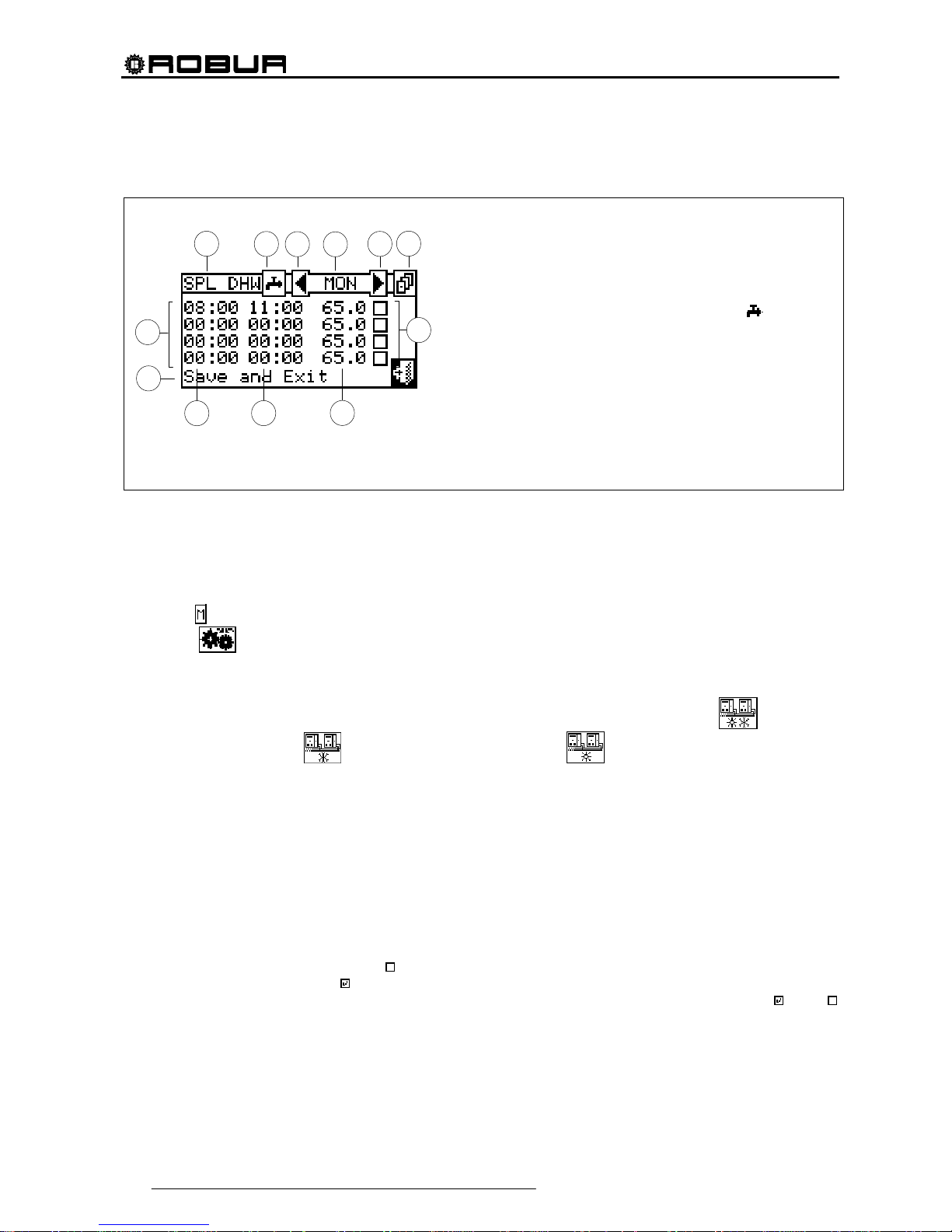
Direct Digital Controller
40 Direct Digital Controller fw 4.013 – Ed. 01/2013
Separable plant T timer cycle programming.
Figure 9 indicates how the DDC display appears when programming the separable plant water T timer cycles.
Figure 9 – SCREEN FOR THE PROGRAMMING OF THE PROGRAMMABLE PLANT T TIMER CYCLES
In case of plants managed by several DDC, the programming of the water T timer cycles can be carried out
only by the DDC defined as Master.
In order to program the switching-on T timer cycles for a typical day, follow the instructions below:
1. Select
from the initial screen to gain access to the main menu.
2. Select
to access the “User settings” menu.
3. If requested, enter the user password on the numerical keypad that appears on the display.
4. Select “Plants” from the drop-down menu.
5. Select the plant for which the partial water T timer cycles are to be programmed:
for two-line
cooling/heating plants,
for hot water production plants, or for chilled water production plants.
6. Select “Water setup” from the drop-down menu.
7. Select “Domestic hot water” from the drop-down menu.
8. Select “Split plant water timer” from the drop-down menu
9. Position the cursor on the activation time of the first water T timer cycle and press the knob. Turn the
knob to select the activation time of the first timer cycle and press the knob to confirm. The cursor moves
automatically to the deactivation time of the first timer cycle. Proceed in the same way to program the
deactivation time of the first timer cycle.
10. Set the water set-point temperature for the programmed timer cycle. Press the knob to modify the
temperature value once the cursor is positioned on the number. Turn the knob to modify the value. Press
the knob to confirm.
11. The cursor moves automatically to
for the activation of the timer cycle programmed. Press the knob to
enable the timer cycle. The
symbol indicates that the timer cycle that has just been programmed has
been enabled. NOTE: a water T timer cycle may be disabled at any moment by pressing
. The
symbol indicates that the water T timer cycle programmed has been disabled.
12. Proceed in the same way, repeating steps 9 – 10 - 11 for the programming of any further timer cycles
required.
KEY:
A Programming of separable DHW system timer cycles;
B T timer cycle switching –on time
C Water T timer cycle switching-off time
D Symbol identifying that the system for which the T timer cycles are
being programmed is the sanitary hot water system
;
E Day for which water T timer cycles are being programmed
F Scroll arrows to change day
G Button for copying previous day’s settings to current day
H Checkbox for activation of programmed water T timer cycle
I Setpoint temperature for the programmed period
L Text describing the function highlighted by the cursor
M Activation/deactivation times of water T timer cycles
D
F
H
M
I
A
F
E
G
C
B
L

Direct Digital Controller
Direct Digital Controller fw 4.013 – Ed. 01/2013 41
13. Once the desired timer cycles have been programmed, it is possible to pass to the following day by
selecting the arrow at the top right
. The previous day’s program may be copied for the current day by
selecting
, or the water T timer cycles required for the new day may be programmed.
14. To exit, select
.
If a programming anomaly occurs, appropriate alert messages are displayed:
Water T timer cycle with zero (or “negative”) duration.
Water T timer cycle in conflict with another timer cycle.
3.4.1.2 Ambient Setup
Via this menu, the user may set all the parameters necessary if ambient
thermostating is used (internal ambient temperature of the environment to
be heated/cooled). It is necessary to connect an ambient temperature
sensor, supplied as an optional extra, for this operating mode.
To gain access to the “Environment setting” menu, first configure the
consent in “AmbT” mode or “WCmp” (climatic curve) mode (for further
information, refer to paragraph “On/off command configuration” on page
103).
The parameters that may be programmed for this operating condition are:
3.4.1.2.1 Differential
3.4.1.2.2 Chronothermostat set points
3.4.1.2.3 Chronothermostat
3.4.1.2.1 Differential
This screen shows the differential value set for heating and/or cooling
operation according to the type of plant configured.
NOTE: this setting is only available in ambT mode; it is disabled in
WCmp mode.
Programming of differential
To set the value or values of the ambient air temperature differential, proceed as follows.
1 - Select
from the initial screen to gain access to the main menu.

Direct Digital Controller
42 Direct Digital Controller fw 4.013 – Ed. 01/2013
2 - Select to access the “User settings” menu.
3 - Enter, if requested, the user password on the numerical keypad that appears on the display.
4 - Select “Plants” from the drop-down menu.
5 - Select the appropriate icon:
for two-line cooling/heating plants, for hot water production
plants, or
for chilled water production plants.
6 - Select “Ambient Setup” from the drop-down menu.
7 - Select “Differential” from the drop-down menu.
8 - Position the cursor on the value to modify (Cooling or Heating).
9 - Press the knob to allow the change of the selected value.
10 - Turn the knob to modify the differential value.
11 - Press the knob to confirm the set value.
12 - To exit, select
.
The recommended values for the ambient temperature differential are 1°C (1,8°F) for cooling and –1°C (1,8°F) for heating.
3.4.1.2.2 Chronothermosta t set p o ints
Up to 3 temperature levels may be programmed.
The 3 temperature levels refer to the air temperature in the environment
to be cooled or heated.
NOTE: T1 corresponds to the minimum s ervice level (lower temperat ure
in heating mode, higher temperature in cooling mode)
consequently it is possible only to set values that respect these
conditions (heating: T1 ≤ T2 ≤ T3; cooling: T3 ≤ T2 ≤ T1).
Programming chronothermostat set points
This option allows the user to set three ambient temperature values for operation in COOLING mode and
three ambient temperature values for operation in HEATING mode. These values can then be selected and
used when programming the ambient chronothermostat.
Instructions for setting the three temperatures follow.
1 - Select
from the initial screen to gain access to the main menu.
2 - Select
to access the “User settings” menu.
3 - If requested, enter the user password on the numerical keypad that appears on the display;
NOTE

Direct Digital Controller
Direct Digital Controller fw 4.013 – Ed. 01/2013 43
4 - Select “Plants” from the drop-down menu.
5 - Select
for two-line cooling/heating plants (in this case 6 temperature levels may be set, 3 for the
cooling plant and 3 for the heating plant),
for hot water production plants (in this case there are 3
temperatures to set),
for chilled water production plants (in this case there are 3 temperatures to
set).
6 - Select “Ambient Setup” from the drop-down menu.
7 - Select “Chronot. Set Ptns” from the drop-down menu.
8 - Position the cursor on the first temperature value at the top left of the screen.
9 - Press the knob to allow the change of the selected value.
10 - Turn the knob to modify the value.
11 - Press the knob to confirm the set value.
12 - Repeat the last 3 steps to set the other temperatures.
13 - To exit, select
.
3.4.1.2.3 Chronothermostat
This option allows the user to program the chronothermostat.
The figure on the right shows an example for a typical day. The
chronothermostat allows a temperature value (T1, T2, T3 or “OFF”) to be
set for each half-hour interval during the day.
For the plant to operate in chronothermostat mode, it is necessary to
connect an ambient temperature sensor, supplied as an optional extra, to
the Direct Digital Controller.
Description of the symbols/icons in the main screen:
Indicates that the chronothermostat for heating operation is being programmed.
Indicates that the chronothermostat for cooling operation is being programmed.
Changes the day for which the chronothermostat is being programmed.
Shows the day that is being programmed.
A
B
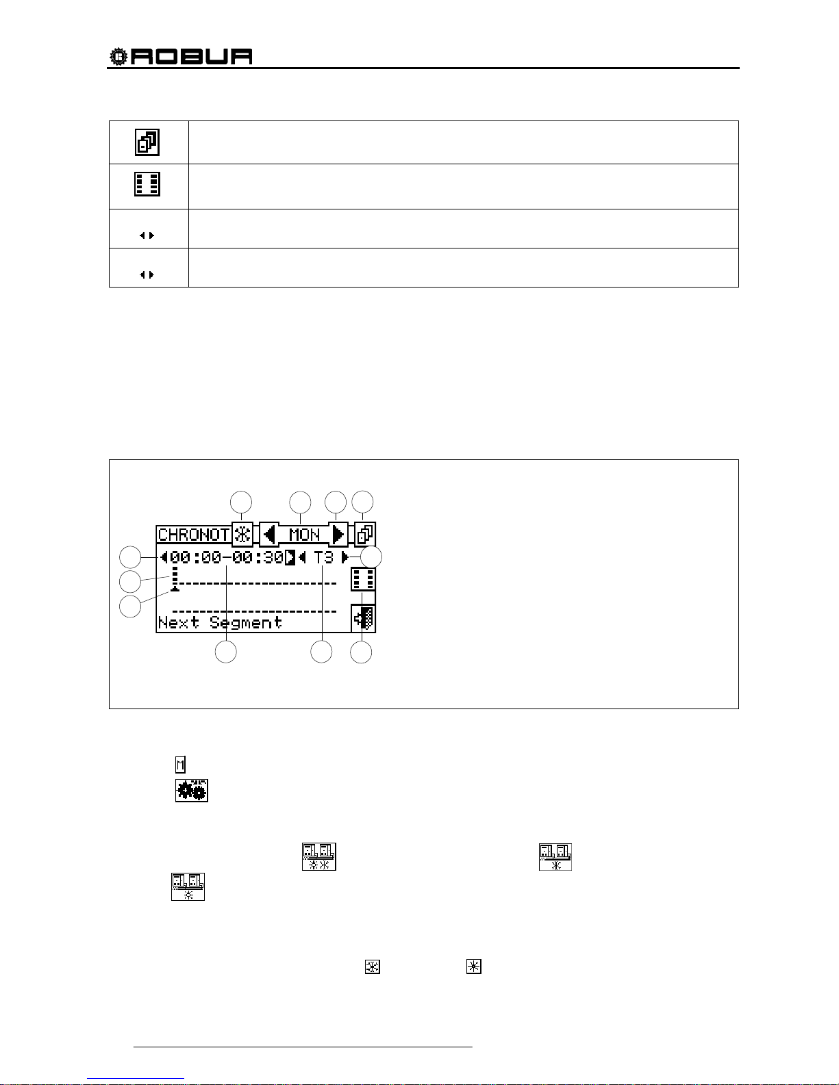
Direct Digital Controller
44 Direct Digital Controller fw 4.013 – Ed. 01/2013
Copies the previous day: allows the program for the current day to be copied from the previous day.
Enables copying of period. This key allows the user to quickly copy the ambient temperature level set for
a specific period to one or more adjacent periods.
Arrows “A”
Allow the user to select one of the 48 periods available, one for each half-hour interval.
Arrows “B”
Allow the user to set a temperature level for the period selected.
A small arrow (see detail “L” in Figure 10 a page 44) on the two rows at the bottom indicates which half-hour
interval is being programmed.
Chronothermostat programming
The use of the chronothermostat allows up to 3 temperature levels to be selected:T1, T2 and T3 (e.g. T3 day,
T2 night and T1 anti-freezing) as well as the switch-off (OFF) for each period selected. It is possible to
program a total of 48 periods with a duration of 30 minutes each, and to assign a specific temperature level to
each period (T1, T2, T3 and OFF).
The figure below shows the screen for programming the weekly chronothermostat. This screen shows all the
buttons and symbols used to enable programming.
Figure 10 – AMBIENT CHRONOTHERMOSTAT PROGRAMMING SCREEN
To carry out chronothermostat programming, follow the instructions below:
1 - Select
from the initial screen to gain access to the main menu.
2 - Select
to access the “User settings” menu.
3 - Enter, if requested, the user password on the numerical keypad that appears on the display;
4 - Select “Plants” from the drop-down menu.
5 - Select the appropriate icon:
for two-line cooling/heating plant; for the hot water production
plant;
for the chilled water production plant.
6 - Select “Ambient Setup” from the drop-down menu.
7 - Select “Chronothermostat” from the drop-down menu.
8 - (Two-line hot/cold plants only) Select button “B” to choose the operating mode for which the
chronothermostat is to be programmed:
for HEATING, for COOLING.
B
D
F
H
C
E
M
A
L
I
G
KEY:
A Arrows to select the last or next period: each period lasts 30
min. It is possible to program 48 periods.
B ID symbol of the plant type: it is possible to program the
cronothermostat for operation in CHILLING and/or HEATING.
C Symbol identifying which day is being programmed.
D Arrows for selecting the previous or following day.
E Button for copying the previous day’s program to the current
day.
F Arrows for selecting the set point to set for the period selected
(T1, T2, T3, OFF).
G Button enabling copy of period.
H Indication of the set point temperature for the period indicated.
I Indication of time of period being programmed.
L Graphic symbol representing the period being programmed.
M Graphic symbol representing the temperature level set.
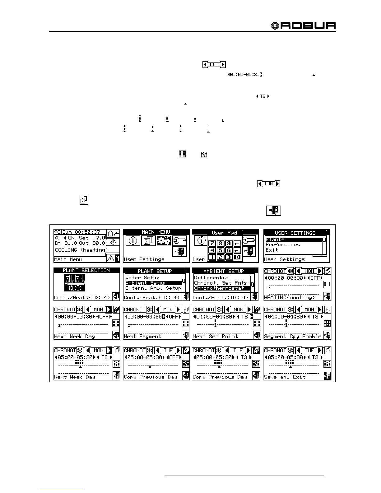
Direct Digital Controller
Direct Digital Controller fw 4.013 – Ed. 01/2013 45
9 - Select one of the arrows “D” as shown in Figure 10 to choose the day of the week; between the two
arrows there is a brief description in letters of the day (
).
10 - Select the period to be programmed via the arrows marked “A” (
) in Figure 10. The symbol
(see label L in Figure 10) indicates the period to be programmed.
11 - Select the set-point temperature level for the period: you can select three temperature levels and the
plant switch-off. Position the cursor on one of the arrows labelled “F” (
) and press the knob to
change the set point temperature. Next to the
symbol some small black squares will appear according
to the level selected:
Functioning in heating mode:
level T3; level T2¸ level T1; OFF.
Conditioning operation:
level T3; level T2¸ level T1; OFF
12 - Select another period using the arrows “A” and repeat the operation described in step 11.
13 - If the same temperature level for a certain number of adjacent periods is desired, enable the copy period
function by means of the copy period button
. The symbol indicates that the copy period button has
been enabled. The use of this function speeds up the chronothermostat programming operations: to copy
the temperature level on adjacent periods use the arrows “A”. To disable the function, press the copy
period button again.
14 - Once programming of the 48 periods is complete, select one of the arrows
to change the day. If
the 48 periods are to be programmed in the same way as the previous day, use the copy previous day
button
.
15 - When all days of the week have been programmed, exit the menu by selecting
.

Direct Digital Controller
46 Direct Digital Controller fw 4.013 – Ed. 01/2013
3.4.1.3 External ambient setup
In this menu all parameters for “ExtT” (external temperature) operating
mode can be set.
To gain access to the “Environment setting” menu, first configure the
consent in “TExt” or “Crvc” mode (climatic curve (for more information
refer to paragraph “On/off command configuration” on page 84).
The parameters that may be programmed in this operating condition
are:
3.4.1.3.1 Set point
3.4.1.3.2 Differential
3.4.1.3.1 Set point
This option allows the user to define external temperature values for
cooling and/or heating operation in “ExtT” (external ambient
temperature) mode.
To exit, select
.
Configuring external set point temperature
Instructions for setting the external temperature follow:
1 - Select
from the initial screen to gain access to the main menu.
2 - Select
to access the “User settings” menu.
3 - Enter, if requested, the user password on the numerical keypad that appears on the display;
4 - Select “Plants” from the drop-down menu.
5 - Select the appropriate icon:
for two-line cooling/heating plants, for hot water production
plants;
for chilled water production plants.
6 - Setup” from the drop-down menu.
7 - Select “Set point” from the scrolling menu.
8 - Position the cursor on the value to be modified (Cooling and/or Heating).
9 - Press the knob to allow the change of the selected value.
10 - Turn the knob to modify the value.
11 - Press the knob to confirm the set value.
12 - To exit, select
.
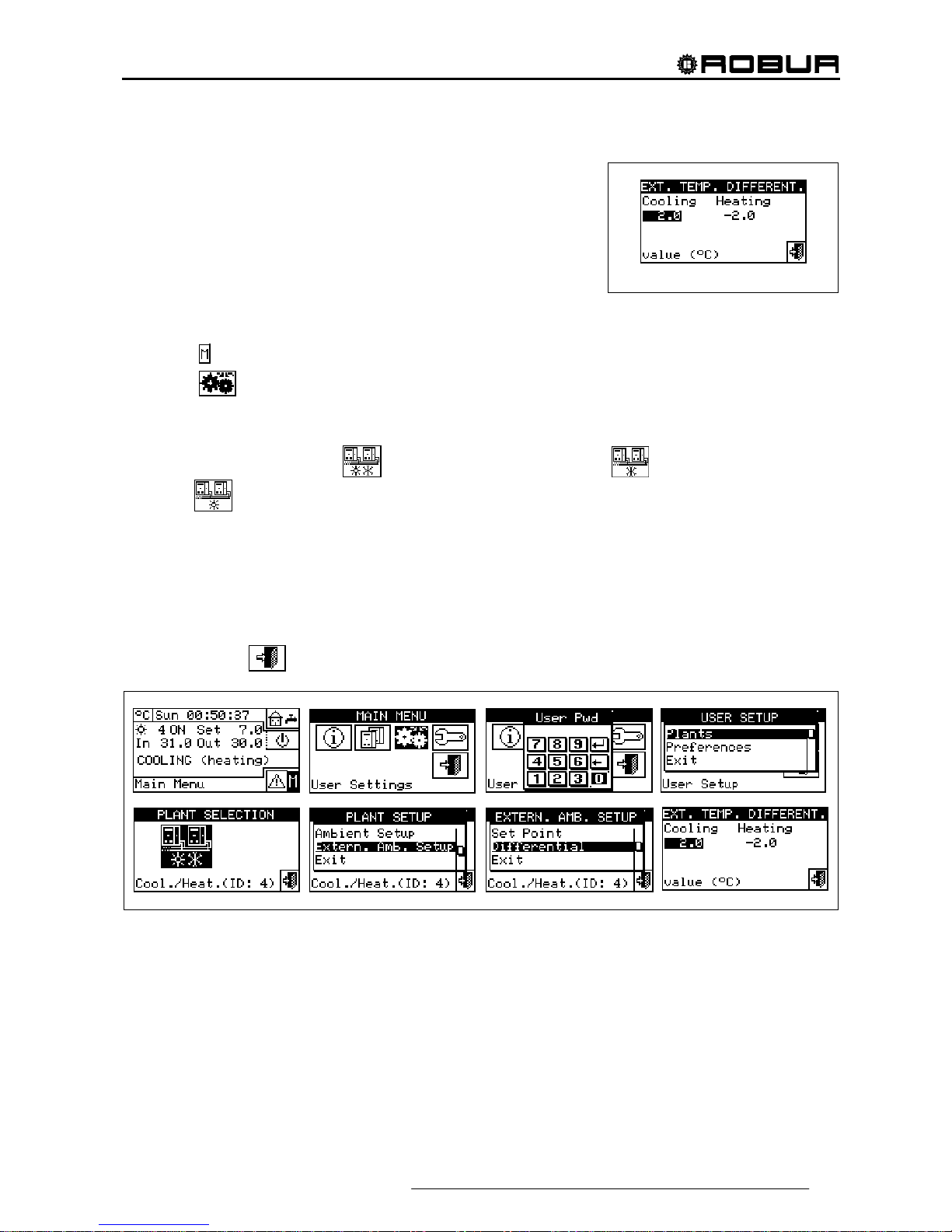
Direct Digital Controller
Direct Digital Controller fw 4.013 – Ed. 01/2013 47
3.4.1.3.2 Differential
This parameter must be set for the “ExtT” (external temperature).
This screen shows the differential value set for heating and/or cooling
operation according to the type of plant configured.
Setting the differential
To set the external air temperature differential value or values, proceed as follows.
1 - Select
from the initial screen to access the main menu.
2 - Select
to access the “User settings” menu.
3 - Enter, if requested, the user password on the numerical keypad that appears on the display;
4 - Select “Plants” from the drop-down menu.
5 - Select the appropriate icon:
for two-line cooling/heating plant; for the hot water production
plant;
for the chilled water production plant.
6 - Setup” from the drop-down menu.
7 - Select “Differential” from the drop-down menu.
8 - Position the cursor on the value to be modified (Cooling and/or Heating).
9 - Press the knob to allow the change of the selected value.
10 - Turn the knob to modify the differential value.
11 - Press the knob to confirm the set value.
12 - To exit, select
.

Direct Digital Controller
48 Direct Digital Controller fw 4.013 – Ed. 01/2013
3.4.2 PREFERENCES
From the user settings menu, select “Preferences” to access the dropdown menu where it is possible to set the following parameters:
3.4.2.1 Language
3.4.2.2 Date and Time
3.4.2.3 Temperature Measurement Unit
3.4.2.4 Alarm Beeper
3.4.2.5 Display Options
3.4.2.6 User Password Setup
3.4.2.1 Language
The following languages are available for viewing the indications on the
display: Italian, English, French, German, Spanish.
Select “Exit” to return to the list of preferences.
If a language is selected by mistake, wait for 30 minutes until the DDC returns automatically to the main
screen, then proceed as follows:
1 - Select
from the initial screen to gain access to the main menu.
2 - Select
to access the “User settings” menu.
3 - Position the cursor by turning the knob on the second line of the drop-down menu, and press the knob.
4 - A second drop-down menu appears. Simply select the first line by pressing the knob.
5 - Turn the knob to choose the language and press the knob to confirm the choice.
6 - Wait for the change to the language selected.
7 - To exit, select
.
3.4.2.2 Date and Time
In this screen, current time and date may be modified.
Setting current date and time
1 - Select
from the initial screen to gain access to the main menu.
2 - Select
to access the “User settings” menu.
3 - If requested, enter the user password on the numerical keypad that appears on the display.
4 - Select “Preferences” from the drop-down menu.
5 - Turn the knob to scroll the cursor downwards until “Date and time” is highlighted and press the knob to
access the submenu.
6 - To modify the date and/or time, turn the knob to position the cursor on the value to be modified.
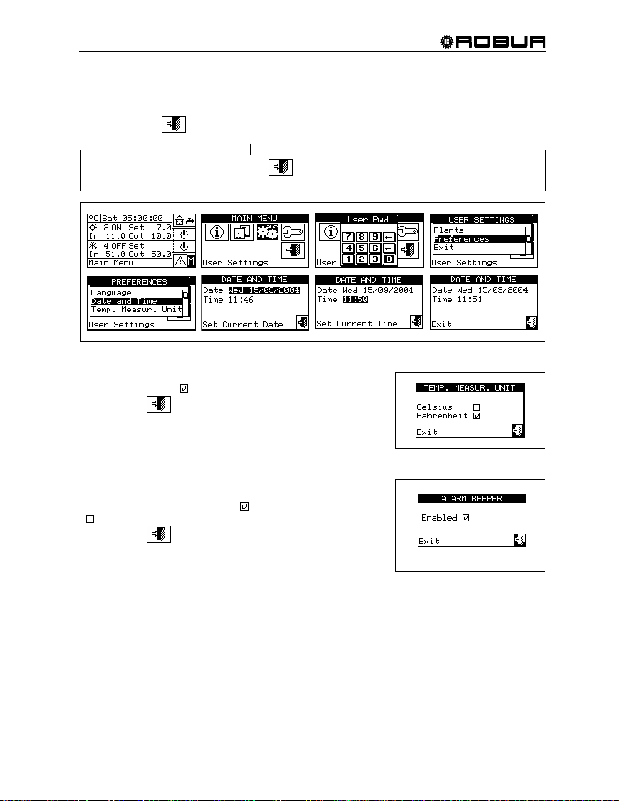
Direct Digital Controller
Direct Digital Controller fw 4.013 – Ed. 01/2013 49
7 - Press the knob. The figure selected will start to flash.
8 - Turn the knob to change the value and press the knob to confirm.
9 - To exit, select
.
The clock is restarted once the exit button has been pressed and if at least one of the two fields has
been selected.
3.4.2.3 Temperature Measurement Unit
This screen shows the current temperature units. To modify the unit,
position the cursor on
and press the knob to confirm.
To exit, select
.
3.4.2.4 Alarm Beeper
The Direct Digital Controller is equipped with a beeper that is activated
each time an alarm regarding the operation of the units managed
occurs. To disable the beep select
and press the knob to visualise
.
To exit, select
.
NOTE
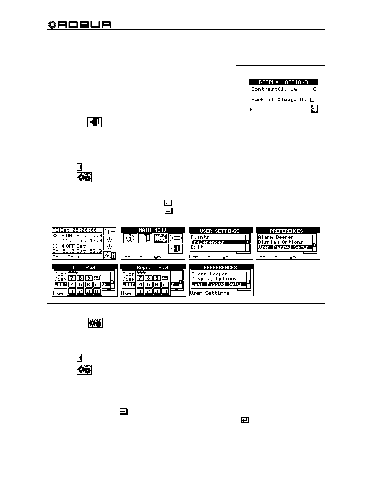
Direct Digital Controller
50 Direct Digital Controller fw 4.013 – Ed. 01/2013
3.4.2.5 Display Options
This option allows the user to adjust the contrast of the graphic display.
To adjust the contrast:
1. Position the cursor on the contrast level.
2. Press the knob. The number starts to flash.
3. Turn the knob to modify the value.
4. Press the knob to confirm the contrast level chosen.
5. Select "Lighting always On” and the backlighting stays on, otherwise
it will switch of after 15 minutes of Encoder inactivity.
To exit, select
.
3.4.2.6 User Password Setup
This option allows the user to set/disable the user password.
To set the user password, follow the instructions below:
1 - Select
from the initial screen to gain access to the main menu.
2 - Select
to access the “User settings” menu.
3 - Select “Preferences” from the drop-down menu.
4 - Select “Set user password” from the drop-down menu.
5 - Enter the password requested and select to confirm.
6 - Enter the new password again and select
to confirm.
Once the password has been enabled, it must be entered every time it is necessary to access the “User
settings” menu (
).
Each time the password is entered to access the User settings menu, it remains active for 10 minutes after
exiting from the menu.
Instructions for modifying or disabling the user password follow.
1 - Select
from the initial screen to gain access to the main menu.
2 - Select
to access the “User settings” menu.
3 - If requested, enter the user password on the numerical keypad that appears on the display.
4 - Select “Preferences” from the drop-down menu.
5 - Select “Set user password” from the drop-down menu.
6 - If a user password is present, a numerical keypad appears on the screen. Enter the old password via this
keypad and then select
to confirm it.
7 - The screen asks for the new password to be entered; enter it and select
.
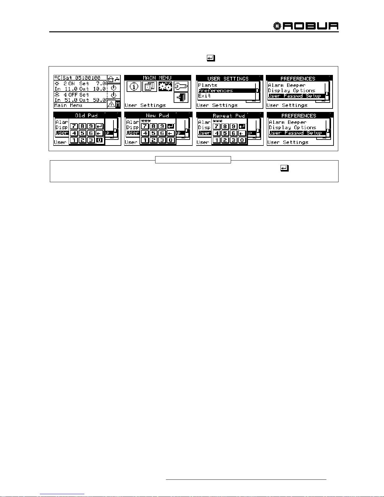
Direct Digital Controller
Direct Digital Controller fw 4.013 – Ed. 01/2013 51
8 - To confirm the new password, enter it again and select .
To disable the password, do not enter a new password at steps 7 and 8 - simply select .
If the user password is disabled, it is not necessary to enter it to access the “User settings menu”.
If an incorrect password is entered, press Enter. The DDC returns to the previous menu.
NOTE

Direct Digital Controller
52 Direct Digital Controller fw 4.013 – Ed. 01/2013
4 INSTALLATION
4.1 CONNECTING THE DIRECT DIGITAL CONTROLLER
Before proceeding with operations for the creation of the electrical system, the professionally
qualified personnel concerned is urged to read carefully the “Warnings”
contained in Section 1,
“GENERAL WARNINGS”, of this manual: they provide important indications regarding installation safety
and references to current norms.
Incorrect installation may cause damage to persons, animals or things, for which the manufacturer
may not be deemed responsible.
4.1.1 GENERAL INFORMATION
The connection of the Direct Digital Controller (DDC) requires:
Power supply to the Direct Digital Controller;
Connection of the DDC and all units via a CAN-BUS cable.
BEFORE CARRYING OUT ANY OPERATION TO CONNECT THE DIRECT DIGITAL CONTROLLER,
DISCONNECT THE POWER SUPPLY FROM THE UNITS BY MEANS OF THE MAIN POWER SWITCH
PROVIDED BY THE ELECTRICAL INSTALLATION TECHNICIAN.
Power supply of the Direct Digital Controller
The Direct Digital Controller must be supplied by a 230/24 V.a.c safety
transformer - 50/60 Hz power no less than 20 VA (not supplied); in
particular, this transformer must comply with standard EN 61558-2-6.
Use a 3 x 0, 75 mm 2 electrical connecting cable and make the
connections on the terminals of the 4-pole connector located at the
bottom left of the rear of the DDC, respecting the polarity as in the
diagram on the right
- terminal 1 = 24 V;
- terminal 2 = 0 V;
- terminal 3 = ground.
The maximum length for this cable is 1 m.
Warning: in any case, terminal 3 of the DDC’s 4-pole connector must
be connected to a safety ground (RCO < 1Ω).
The Direct Digital Controller is additionally equipped with a backup
battery which, in the absence of electrical power, is able to preserve
values set in memory. The duration of the backup battery is
approximately 7 years, after which it is necessary to replace it (by
contacting a ROBUR Technical Assistance Centre).
Connecting the Direct Digital Controller to the units
The Direct Digital Controller must be connected to the units via a CAN-BUS cable, to create a data
communication network, characterised by a series of “n” nodes as indicated in the examples in Figure 11 or
Figure 12.
WARNING
Respect the polarity:
1 = 24 Vac
2 = 0 Vac
Obligatory ground
DIRECT DIGITAL
CONTROLLER (rear
view)
NOTE

Direct Digital Controller
Direct Digital Controller fw 4.013 – Ed. 01/2013 53
Figure 11 – EXAMPLE OF CONNECTION OF DIRECT DIGITAL CONTROLLER TO SEVERAL GA SERIES UNITS
Figure 12 – EXAMPLE OF CONNECTION OF DIRECT DIGITAL CONTROLLER TO SINGLE PREASSEMBLED GAHP SERIES UNIT
For total cable length of up to 200m and communication networks with MAX 6 nodes (example 1 Direct Digital
Controller connected to 1 RTCF 300-00) a simple 3 x 0, 75 mm
2
shielded cable may be used. In all other
cases, use a CAN-BUS cable, available as a ROBUR accessory, or follow the specifications given below.
NAME OF CABLE MARKINGS / COLOURS MAX. LENGTH note
Robur
ROBUR NETBUS H=BLACK L= WHITE GND= BROWN 450 m
- - - - - - - - -
Honeywell SDS 1620
BELDEN 3086A
TURCK type 530
H=BLACK L= WHITE GND= BROWN 450 m
DeviceNet Mid Cable
TURCK type 5711 H= BLUE L= WHITE GND= BLACK 450 m
Honeywell SDS 2022
TURCK type 531 H=BLACK L= WHITE GND= BROWN 200 m
In all cases,
the fourth wire
may not be
used
Table 1 – EXAMPLES OF CAN-BUS CABLES FOR THE CONNECTION OF THE DIRECT DIGITAL CONTROLLER TO GA and GAHP SERIES UNITS
Diagrams and procedures for connecting the Direct Digital Controller to ROBUR units or to other
Robur devices are contained in the specific Installation, Operation, Activation and Maintenance
Manuals supplied with the units themselves.
For the operation of connecting the DDC, please consult this specific documentation.
WARNING
ACF AYF
AYF
DIRECT DIGITAL
CONTROLLER
1st NODE
2nd CAN-BUS CABLE
NODE
(
see Table 1)
DIRECT DIGITAL
CONTROLLER
1st NODE
MULTIPLE UNITS WITH CAN-BUS CABLE BETWEEN SINGLE MODULES ALREADY CONNECTED
3 th INTERNAL NODE
4 th INTERNAL NODE
5th INTERNAL NODE
2 rd INTERNAL NODE
AR AR AR
AR
3rd CAN-BUS CABLE
NODE (see Table 1)
4th CAN-BUS CABLE
NODE (see Table 1)

Direct Digital Controller
54 Direct Digital Controller fw 4.013 – Ed. 01/2013
4.1.2 CONNECTING THE DIRECT DIGITAL CONTROLLER
The following connection terminals are located on the rear of the Direct Digital Controller (see Figure 13):
2-pole connector for ambient air temperature sensor, supplied as an optional accessory, if specified (see
detail A in Figure 13);
3-pole connector for alarm signal relay contacts (see detail B in Figure 13);
4-pole connector for 24 Vac power supply. Current is supplied to the DDC by a 24 Vac, 50/60Hz single
secondary transformer (see detail C in Figure 13);
6-pole connector for external operation commands, if specified (see detail D in Figure 13);
6-pole CAN-BUS connector for connecting the DDC to the units (see detail E in Figure 13).
A standard male 9-way connector (RS232 serial port) is located on the front of the Direct Digital Controller for
connection to a PC (see Figure 1 on page 7).
In particular applications, an external alarm signal may be required for high chilled water temperature and/or
for low hot water temperature, or for a general alarm that allows any anomalies in the units to be signalled.
To this end, a specific terminal with 3 contacts (see detail B in Figure 13) is provided on the rear of the Direct
Digital Controller for the activation, via a relay, of an alarm signal, such as a light, siren or other device (for
further information see Paragraphs 4.4.2.6.7 – “Temperature Alarm Setup (Master DDC only)” on page
100 and 4.4.2.4 – “Alarm output setup” on page 86.
This connection must only be used to control external equipment at very low safety voltage (SELV) up to a
maximum of 24 V and at a maximum current of 1 A. Do not connect external equipment to a 230 V supply.
Figure 13– REAR VIEW OF DIRECT DIGITAL CONTROLLER and DETAIL OF ELECTRICAL CONNECTIONS
KEY
TERMINALS FOR CONNECTION OF INTERNAL OR EXTERNAL AIR
SENSOR (NTC 10K), IF SPECIFIED (see Paragraph 4.5.3.1.4)
TERMINALS FOR CONNECTION TO EXTERNAL ALARM SYSTEMS
- terminal 1 COM
- terminal 2 NO
- terminal 3 NC
TERMINALS FOR 24 Vac FOR DIRECT DIGITAL CONTROLLER POWER
SUPPLY
Respect connection polarity
- terminal 1 24 Vac
- terminal 2 0 Vac
- terminal 3 earth
- terminal 4 not used
6-POLE CONNECTOR FOR EXTERNAL CONSENTS
(see Paragraphs 4.5.3.1.2 or 4.5.3.1.3)
- terminal 1 R (24 Vac)
- terminal 2 W (heating)
- terminal 3 Y (cooling)
- terminal 4 0 (0 Vac)
- terminal 5 NA (not connected)
- terminal 6 R (24 Vac)
CAN-BUS CABLE CONNECTION
RS232 PORT REAR CONNECTION (RJ45)
Alternative connection to front connection, for the same RS232 port
RS485 PORT CONNECTION
(see Paragraph 4.4.1.13)
- terminal 1 A (TXD/RXD+)
- terminal 2 B (TXD/RXD-)
- terminal 3 Common (connected to the system mass and earth)
- terminal 4 Cable sheath (connected to the system mass and earth)
NOTE
A
C
D
E
B
A
B
C
D
E
G
F
F
G

Direct Digital Controller
Direct Digital Controller fw 4.013 – Ed. 01/2013 55
To carry out the electric connection between DDC and RB100 we suggest to refer to the “Electric installer
section” of the booklet provided with the RB200 device (Code D-LBR468).
To carry out the electric connection between DDC and RB200 we suggest to refer to the “Electric installer
section” of the booklet provided with the RB200 device (Code D-LBR632).
APPLYING THE DIRECT DIGITAL CONTROLLER
For internal installation, the Direct Digital Controller must be applied as a panel by carrying out the following
operations (see Figure 14):
Create a 155 by 151 mm rectangular opening;
Position the Direct Digital Controller over the opening created and mark the 4 points of the holes by which it
is to be fixed in place;
Make 4 holes of 4 mm in diameter;
proceed with the operation of applying the Direct Digital Controller over the opening in the panel with the
screws and nuts (supplied).
Figure 14 – DISTANCE BETWEEN FIXING HOLES FOR DIRECT DIGITAL CONTROLLER
The operating temperature range of the Direct Digital Controller is 0 ÷ 50 °C (32° ÷ 122°F). If the temperature
of the installation environment is below zero freezing, the Direct Digital Controller continues to function
correctly to -10 °C (14°F), but its LCD screen may not be able to display data.
4.2 DESCRIPTION OF AUXILIARY BOILER OPERATING METHODS FOR HOT
SERVICE ON BASE PLANT PART
Limited to the hot service on the base plant part (heating and/or base domestic hot water) obtained with a
mixed generation system (heat pump and auxiliary boilers), two different operating modes are available for the
auxiliary boilers, selected using specific parameters:
• Complement mode
This mode is used for plants in which the auxiliary boilers complement, but do not substitute, heat pumps
in all the plant operating field. This means that the heat pumps can also work at max. thermal load, and
therefore that the plant always requests delivery and return water temperatures that are compatible with
the maximum permitted temperatures of the heat pump. It follows that the installed power (sum of the
power of the heat pumps and the auxiliary boilers) is usually equal to the total power requested of the
plant.
NOTE
NOTE

Direct Digital Controller
56 Direct Digital Controller fw 4.013 – Ed. 01/2013
• Complement and substitution mode
This mode on the other hand is used for plants in which, at a high thermal load, it is foreseen that the
temperatures requested for delivery and/or return water are incompatible with the maximum permitted
temperatures of the heat pumps. In this type of plant, starting with a given thermal load we must keep the
heat pumps off and use only the auxiliary boilers; we must therefore install auxiliary boilers that are able
to provide 100% of the maximum power requested of the plant (nominal plant power). Therefore the
system assumes that the nominal plant power is equal to the total power of the auxiliary boilers and
delivers this power according to one of the following diagrams:
A - As far as is possible (low and medium thermal load) it enables the h eat pumps and possibly a
fraction of the auxiliary boilers, so that the total enabled power corresponds to the nominal plant
power.
B - At high thermal load, and in particular when the requested temp eratures are incompatible with
those permitted by the heat pump, it disables the heat pumps and enables all the auxiliary boilers,
so that the total enabled power is still equal to the nominal plant power.
The system passes from one power delivery layout to the other maximising the use of the heat pumps,
as far as is permitted by the temperatures requested of the plant.
If necessary it is possible to explicitly declare the nominal plant power value, using a special parameter;
this is useful in the event that the total power of the auxiliary boilers is higher than the nominal plant
power.
It is clear that this boiler operating mode requires the use of variable water set points according to the
external temperature (based on the climatic curve), otherwise the system will always work with water
temperatures that are not compatible with the heat pumps
For the description of the setting operations for these parameters, refer to the paragraph 4.4.2.6.2 “Auxiliary
boiler operation” on page 94 and 4.4.2.6.3 Rated plant power on page 95.
Warning generation for premature substitution of the heat pumps
When using the "Complement and substitute" mode it is possible to specify a delivery or return temperature
limit value; the delivery value is used if the delivery is regulated and the return value in the opposite case.
If the passage from layout A to layout B (see previous paragraph) takes place when the temperature
measured on the manifold on which the regulation takes place is less than the specified limit value, the
warning W1027 is generated and memorised in the event history. This is used to underline situations in which
the heat pumps are disabled with lower manifold water temperatures than those nominally set and which lead
to a lower use of the heat pumps; this warning acts for information only, and does not affect the system
functionality. To obtain a correct diagnostic, set an appropriate limit value according to the plant
characteristics.
These parameters are found in the hot service regulation parameters page of the base plant part (see 4.3.1
HEATING SERVICE).
Variant of the Complement and substitution: Progressive complement and substitute
Again in the case of using the "Complement and substitution" mode it is possible to select advanced settings
which substitute the heat pumps with auxiliary boilers progressively rather than in a single moment. When the
operating limit of the heat pumps is reached, corresponding to the passage from the power delivery layout A to
layout B described above, the system attempts to substitute a single heat pump with the auxiliary boilers
(rather than substituting them all as takes place in the "standard complement and substitution" mode);
subsequently it continues to monitor the temperatures; once the limit operating condition of the heat pumps is
reached again, the system substitutes another heat pump with power generated by the auxiliary boilers. This
NOTE
NOTE
NOTE

Direct Digital Controller
Direct Digital Controller fw 4.013 – Ed. 01/2013 57
process is repeated when necessary and can lead to the progressive substitution of all the heat pumps or their
progressive re-inclusion.
This use of this advanced variant of the complement and substitution mode is subordinate to the satisfaction of
the following requirements:
• Hydraulic configuration of the boilers in series with the heat pumps (see the “Applications manual”)
• Installation of an additional temperature probe on the return manifold of the heat pump
These two requirements imply the use of the RB200 device, which is able to manage the temperature
probes of the effective delivery and return manifolds in the serial hydraulic configuration, and the
additional probe on the return manifold of only the heat pumps.
• Correct setting of some additional parameters, concerning an auxiliary regulator which manages the
substitution and progressive re-inclusion of the heat pumps
These parameters are found in the hot service regulation parameters page of the base plant part (see
4.3.1 HEATING SERVICE).
Hydraulic configuration of the auxiliary boilers in parallel or in series with the heat pumps
Whatever the auxiliary boiler operating mode, it is possible to use the hydraulic configuration in parallel or in
series.
In the parallel configuration, the return pipes from the auxiliary boilers are connected directly to the plant return
manifold, like those in the heat pumps; similarly, all the delivery pipes are connected to the plant delivery
manifold. In this case, the carry out the regulation, the DDC may use:
• If the auxiliary boilers are AY modules (Robur), the average temperature read by the machine probes,
or dedicated manifold probes, managed by the RB200.
• If the auxiliary boilers are third party, only dedicated manifold probes, managed by the RB200.
In the serial configuration, the return pipes from the auxiliary boilers are connected to the delivery manifold of
the heat pumps and the delivery pipes to the plant delivery manifold; only the return pipes from the heat
pumps are connected to the plant return manifold. This configuration is advantageous when the plant, at high
thermal load, requires a higher delivery temperature than the maximum permitted by the heat pumps [60 or 65
°C (140 or 149° F) according to the models] and develops a higher Delta T than that of the heat pumps [10 °C
(18°F)]. In this case, to carry out the regulation, the DDC must always use dedicated manifold probes,
managed by the RB200, which may be positioned on the effective plant delivery and return manifolds.
For more information on this subject, refer to the "Applications Manual” (D-LBR630).
4.3 DESCRIPTION OF THE REGULATION WATER TEMPERATURE ALGORITHM AND
OF THE RELATIVE PARAMETERS
4.3.1 HEATING SERVICE
Objective of the regulation
The Digital Control Panel regulates the water temperature with the objective of maintaining it within a band
centred on the set point. The range of this period is defined by the relevant “Water differential” parameter, as
indicated in Figure 15. The default value of the parameter is 2 °C (3,6 °F) [i.e. ± 1 °C (±1,8° F) with respect to
the set point value]; for normal applications it is recommended to use this value.
NOTE
NOTE
Direct Digital Controller
58 Direct Digital Controller fw 4.013 – Ed. 01/2013
Figure 15
To make the regulation, the DDC manages switch-on and switch-off in cascade mode of the different types of
machines available, adapting the power supplied to the system heat load.
Machine categories
On the basis of their type, the machines are assigned to “categories” which have different properties to each
other, in a way to allow the control panel to manage the various types of machine with differentiated logic and
parameters. However, the machines have equivalent features within a category.
In heating mode, the existing categories are:
• Category 1
The hot modules of all current Robur heat pumps are automatically assigned to this category.
• Category 2
This category is reserved for future Robur products.
• Category 3
All current Robur heat pumps in the AY line are automatically assigned to this category.
• Categories 4 - 7
Any third party boilers can be assigned by the installer to these categories. For setting instructions refer to
paragraph 4.4.1.9 “Third party product category” on page 76.
Machine power of a category
The power of the individual machine belonging to it is defined via a parameter for each category.
For categories 1 and 3 (heat pumps and AY boilers) the pre-set value that cannot be modified is 35 kW.
For each of the categories 4-5-6-7 (third party boilers) the value that can be set by the installer is from 1 to
1680 kW.
Switch-on priority of a category
An ignition priority is associated to each category, expressed via a parameter with value from 0 to 6, which
determines the priority of use of the machines belonging to this category. The higher the value the higher the
priority.
For category 1 (Robur heat pumps) the value, which is set automatically and cannot be modified, is 6,
corresponding to maximum priority. For category 3 (Robur AY boilers) the value set by default is 4, but this
can be modified from 0 to 4. For categories 4-5-6-7 (third party boilers) the value set by default is 3, but again
this can be modified from 0 to 4. Therefore the system will always switch on the heat pumps first and will use
the boilers only when the thermal load is higher than the installed power of the heat pumps; the installer can
decide the relative switching on priority of all categories used for boilers, whether Robur or third party. Please
note that it is possible to assign the same switching on priority to several categories used for boilers; the DDC
will maintain a balanced operating time for boilers belonging to equal priority categories.
Number of stages of a category
The number of stages used by the regulation system is defined for every category. This is determined by a
parameter, which can be set in the range from 1 to 10.
The parameter must always be set at the value corresponding to the number of the stages desired.
If the number of machines is not an exact multiple of the parameter value, the system will use the number of
stages corresponding to the value of the parameter, but the stages will not be uniform, i.e. they will be made
up from different amounts of machines. The DDC will maintain a balanced operating time of the machines,
modifying the assignment of the machines to various stages of the category every 24 hours.
SP
SP Water set point
DF Water differential
DF

Direct Digital Controller
Direct Digital Controller fw 4.013 – Ed. 01/2013 59
When the values of the number of stages in each category are set initially, or if they are subsequently varied,
it is also necessary to modify the setting of the other parameters; refer to paragraph Default values of the
parameters and indications for correct choice of their values (categories 1 and 3)” on page 103 and in
particular Table 2.
Prevention time, enabling integral and prevention integral of a category, description of the regulation
algorithm
These three parameters are also defined for each category, which affect the regulation algorithm used by the
system to maintain the temperature of the water inside the differential period.
The regulator operates by switching the machine that constitutes the various stages of the various categories
on and off. When the regulator is operating on the stages of a given category, it uses the values of the three
parameters corresponding to this category. This allows to optimise the regulation on the basis of the features
of the specific category (number and power of the stages, type of heat generator).
Successively, the regulation algorithm is illustrated via an example of evolution of the water temperature
through time. It is assumed that the system is made up from two stages belonging to a unique category and
that the initial condition is within machines all off and temperature of the water within the differential band. In
the following description, refer to Figure 16.
A. Zone 1 of the graph in Figure 16: while the temperature of the water remains within the differential band
centred around the set point, the regulator keeps all machines off.
B. Point 2: when the falling water temperature, exits the differential band, the regulator switches the
machines, which constitute the first stage of the category at highest priority, on.
Note: subsequently, switch-on of the machines that constitute a stage data will be defined for brief
switch-on of the stage
C. Zone 3: if the energy supplied by the first stage is such to make the temperature of the water rise quickly
inside the differential band and keep it there, the regulator does not perform other interventions and keeps
the first stage on.
D. Point 4 and Zone 5: if the energy supplied by the first stage causes the water temperature to rise above
the differential band, the regulator switches the first stage off and keeps it off in zone 5.
E. Point 6 and Zone 7: in this case, the energy supplied by the first stage is not sufficient to cause quick rise
of the water temperature. When the first stage has been switched back on in point 6, the regulator, after a
delay equal to the value inserted for the “prevention time” parameter, starts to calculate the energy
deficit, represented by the dotted area in zone 7. If the dotted area should reach the value set for the
“enabling integral” parameter, the regulator “would release” the second stage and switch it on. In the
case represented in zone 7, instead, the temperature of the water rises within the differential band before
the dotted area reaches this value, therefore the regulator does not switch the second stage on, but keeps
the first stage on, as the temperature of the water remains within the differential band.
F. Point 8 and Zone 9: in the same way as the case described in D, the regulator switches the first stage in
point 8 off and keeps it off in zone 9.
G. Points 10 and 11 and zone 12: the situation is similar to that described in E, but in this case, after the
delay equal to “prevention time”, the dotted area that represents the energy deficit reaches the value set
for the “enabling integral” parameter, therefore the regulator “releases” the second stage and switches it
on (in point 11); it keeps it on in zone 12, i.e. up to when the temperature of the water is below or within
the differential band.
H. Point 13 and zone 14: in the same way as the case described in D, for the first stage, if he energy
supplied by the second stage causes the water temperature to rise over the differential band, the regulator
switches the second stage off in point 13 and starts to calculate the excess energy, represented by the
dotted area in zone 14. If the dotted area should reach the value set for the “
prevention integral”
parameter, the regulator “would block” the second stage and would switch the first stage off. In the case
represented in zone 14, instead, the temperature of the water returns within the differential band before
NOTE

Direct Digital Controller
60 Direct Digital Controller fw 4.013 – Ed. 01/2013
the dotted area reaches this value, therefore the regulator does not "block" the second stage and keeps
the first stage on. The second stage is maintained off in all of zone 14.
I. Point 15 and zone 16: because the second stage has not been "blocked", it is switched back on
immediately when the falling temperature of the water, escapes the differential band and zone 16 is kept
on.
J. Points 17 and 18 and zone 19: the situation is similar to that described in H.: the regulator switches off
the second stage of point 17, but in this case in the subsequent point 18 the dotted are that represents the
excess energy reaches the value set for the parameter “prevention integral”; therefore in point 18 the
regulator “releases” the second stage and switches off the first; it then maintains this state in zone 19. In
zone 19 the system is therefore once again in the situation of zone 1, described in A.; therefore all
possible subsequent evolutions of the system fall within the cases already described; for example,
in point 20 the first stage will be switched on again, as previously occurred in point 2.
It is possible to summarise the functioning of the regulation algorithm with the following rules:
• In a given moment, the regulator works with a certain number of stages released and the rest blocked.
• The first stage of the category with highest priority is never blocked.
• All blocked stages are always off; all released stages, except the last, are always on; the last released
stage is switched on or off when the temperature of the water, respectively falling or rising, exits the
differential band.
• A blocked stage is released (and switch-on) if the area that represents the energy deficit, calculated
starting from the expiry of “prevention time”, reaches the “enabling integral” (Figure 16) value.
• A released stage is blocked (and the previous stage is switched off) if the area that represents the excess
energy reaches the “prevention integral” value.
NOTE
• The release and block technique of the stages, based on the “enable and prevention integrals”, allow to
“centre” the power of generation adapting it to the load of the system. In a given load condition, the system
maintains some systems stably of and all of the others, except one, on. The remaining stage is switched
on or off alternately to regulate the temperature of the water, keeping it within the differential band. This
regulation adapts the generation power also when faced with fluctuations contained in the load. However,
successively, to significant load variations, one or more further stages are blocked or released in
succession, until the generation power is taken almost back into equilibrium with the load. At this point the
system goes back to regulating the alternate switch-on/off of an individual stage.
• The “prevention time” allows to consider the fact that the machines start to produce energy only after a
certain time from start-up. Starting from the moment that the regulator has switched a stage on, the
prevention time allows to wait that effect is produced on the regulation of this stage, before starting to
calculate the energy defect still present and potentially reach switching on another stage. Therefore the
values of this parameter are linked to the features of the various types of machines.
• As already mentioned previously, if several machine categories are present, on increase of the heat load,
the system first switches on all stages available in the highest priority category and then, if necessary,
passes to switching the stages on of the priority category immediately lower, and so on. When the heat
load drops the system switches the stages off in the reverse order. Each individual time, the regulator uses
the parameter values defined for the category with lowest priority that have at least one stage on; for
example, in the case of the system with two machine categories, the regulator uses the values defined for
the category for highest priority until only the stages of this category are switched-on. From the time that at
least one stage of the second category is switched on, it passes to using the values of the parameters of
the same. It goes back to using the values of the first category when all stages of the second are off again.
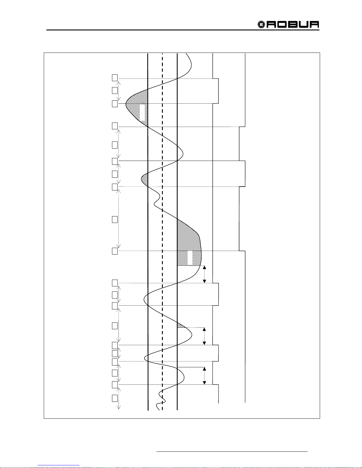
Direct Digital Controller
Direct Digital Controller fw 4.013 – Ed. 01/2013 61
Tinhib
Enabl.
Inhib.
1 3 2 5 4 7 6 9 8 11 10 12 14 13 16 15 18 17 19 20
Stage I
Stage II
ON
OFF
Tinhib
Tinhib
ON
OFF
Figure 16

Direct Digital Controller
62 Direct Digital Controller fw 4.013 – Ed. 01/2013
Minimum switch-on time of a category
This further parameter is present for every category. This allows to define the minimum switch-on time of
every stage of the category and has the purpose of preventing that the machines are kept on for a period that
is too brief, with negative impact on the yield of the same. In practice, when a stage is switched on, it can be
switched off only after the “minimum switch-on time” has passed, whatever the rules of the regulation
algorithm described in the relative paragraph; for example, referring to Figure 16, if the time passing between
points 2 and 4 is less than the “minimum switch on time”, the first stage would not be switched off in point 4,
but later, after the “minimum switch on time” calculated from point 2. It is clear that the use of too high a
value of this parameter can lead to poor regulation, as the respect for the minimum switch on time will cause
frequent and consistent breaches in the rules of the normal algorithm; on the other hand, too low a value will
lead to the machine being switched on for very short periods, which will compromise yield.
Default values of the parameters and indications for correct choice of their values (categories 1 and 3)
Default values
Parameter Value of Categ. 1 Value of Categ. 3 Recommended setting
Machine power 35 kW 35 kW Not modifiable
Priority 6 4 Not modifiable
Prevention time 5 minutes 2 minutes Use default values
Mi. switch-on time 7 minutes 3 minutes Use default values
Number of stages 10 10
Use the maximum value
possible for the number of
machines present
Enable integral
6 °C * minutes
(10,8 °F * minutes)
6 °C * minutes
(10,8 °F * minutes)
Disable integral
8 °C * minutes
(14,4 °F * minutes)
8 °C * minutes
(14,4 °F * minutes)
Use the semi automatic
configuration (refer to paragraph
4.4.2.6.4 “Regulation
parameters” on page 96), which
calculates the value of these
parameters according to the
other data set for all categories;
the calculation is made when
exiting the configuration panel
Table 1 – REGULATION PARAMETER DEFAULT VALUESHEATING OPERATION (categories 1 and 3)

Direct Digital Controller
Direct Digital Controller fw 4.013 – Ed. 01/2013 63
Default values of the parameters and indications for correct choice of their values (categories 4 - 7)
Default values
Parameter Value of Categ. 4 - 7 Recommended setting
Machine power 35 kW
Set the power value in kW of the single
machine belonging to the category
Priority 3 Set a value between 0 and 4
Prevention time 2 minutes
Set a value suited to the type of
machine used
Minimum activation time 3 minutes
Set a value suited to the type of
machine used
Number of stages 10
Use the maximum value possible for the
number of machines present
Enable integral
6 °C * minutes
(10,8 °F * minutes)
Disable integral
8 °C * minutes
(14,4 °F * minutes)
Use the semi automatic configuration
(refer to paragraph 4.4.2.5.4 Regulation
parameters 89), which calculates the
value of these parameters according to
the other data set for all categories; the
calculation is made when exiting the
configuration panel
Table 2 - REGULATION PARAMETER DEFAULT VALUES HEATING SERVICE (categories 4 - 7)
Guide lines for the calibration of the parameters on the basis of the observation of the behaviour of the
system.
The values for the automatically set integrals using the semi-automatic configuration refer to plants with
normal heat inertia.
If systems must be regulated with very low or very high inertia values, it is possible that the regulation
parameters are calibrated differently.
Several guide lines are given below:
• The first indicator of a well-regulated system is that in normal conditions (with constant load) there is
only one intermittent stage.
If, however, there are several intermittent stages in normal running conditions, the integrals must be
increased, both prevention and enabling.
• If the response to load or set point variations is too slow:
o reduce the integrals, both prevention and enabling;
o reduce the number of stages, only after having acted with the previous option.
• If a single stage is too intermittent:
o maximise the number of stages;
o increase the differential [default = 2°C (3,6° F)] without exaggerating so as not to shift too far
away from the set point.
• If too marked overshoots are observed (the temperature rises too much over the set point):
o reduce the prevention inhibition;
• If too marked overshoots are observed (the temperature falls too much below the set point):
o reduce the enabling inhibition;
When a set point is requested that is very near to the operational limits of the machines, if the load is low the
system will regulate badly as the machines will tend to go continuously into limit thermostating.
To prevent this phenomenon that largely worsens yield, it is necessary to intervene with the activation of the
climatic curves or, alternately, reduction of the set point (in heating mode).
In the case of systems with common pump, where the phenomenon is particularly marked, it is also possible
to intervene by reducing the number of stages.
Third party boiler water pump delay
Only for categories 4, 5, 6 and 7, for third party boilers, this parameter is also present. For a given category,
the parameter is present when assigned to boilers with dedicated water pumps controlled by the Robur
system; this has the purpose of establishing the switch off delay for this type of water pump. If more than one

Direct Digital Controller
64 Direct Digital Controller fw 4.013 – Ed. 01/2013
boiler of this type is assigned to a category, the switch off delay is the same for all the water pumps of these
boilers.
Delivery and return limit temperature
For category 1 only, destined for heat pumps, these parameters may also be present. In particular, the
parameters will be present in the event of using the "complement and substitution" operating mode with the
auxiliary boilers. For details on the meaning of these parameters, refer to paragraph 4.2 - DESCRIPTION OF
AUXILIARY BOILER OPERATING METHODS FOR HOT SERVICE ON BASE PLANT PART on page 55.
Auxiliary regulator parameters for "Progressive complement and substitution" mode
For category 1 only, destined for heat pumps, these parameters may also be present. In particular, the
parameters will be present in the event of using the "progressive complement and substitution" operating
mode with the auxiliary boilers. For details on the meaning of these parameters, refer to paragraph 4.2 DESCRIPTION OF AUXILIARY BOILER OPERATING METHODS FOR HOT SERVICE ON BASE PLANT
PART on page 55.
Setting the parameters
For the description of the setting operations of the parameters, refer to the paragraph 4.4.2.6.4 "Regulation
parameters" on page 96 relative to setting the basic system part.
4.3.2 DOMESTIC HOT WATER (DHW) SERVICE
DHW service on the basic system part
Regarding the “base” DHW service, i.e. supplied at the same time as the heating service and on the same
pipes, the regulation is identical to that described previously for the heating service and uses the same values
as the parameters.
DHW service on the separable system part
For the DHW service supplied on the pipes on the separable part of the plant, the regulation algorithm is
identical to that described for the heating system. In this case, however, parameters are used that are
dedicated to allow differentiation of the regulation. To set these, refer to the 4.4.2.5.4 “Regulation parameters”
paragraph on page 89 relative to the settings of the separable system part. The default values of the
parameters are identical to those of the basic system part.
In this case the Delivery and return limit temperature and Auxiliary Regulator parameters are never present
for the "Progressive complement and substitution" mode as the "complement and substitution" operating
mode of the auxiliary boilers is not foreseen on the separable plant part.
4.3.3 CONDITIONING OPERATION
General description
The algorithm used to regulate the temperature of the water is identical to that of the heating mode, except for
inversion of the logic, thanks to which the stages are switched on when the temperature is higher than the
objective and off when lowered. Therefore, for a description of the algorithm, refer to the 4.3.1 “Heating
service” paragraph on page 57.
The “Water differential” parameter also exists in cooling mode, with default value = 2°C (3,6° F) and with the
same meaning described for the heating mode.
Categories of machines and parameters default values
For the conditioning service, the following categories are defined:
• Category 1
The cold modules of all current Robur heat pumps and chillers are assigned to this category.
• Categories 2 and 3
These categories are reserved for future Robur products.
• Categories 4 - 7
Any third chillers can be assigned by the installer to these categories. For setting instructions refer to
Table 4 on page 65.
NOTE

Direct Digital Controller
Direct Digital Controller fw 4.013 – Ed. 01/2013 65
For category 1 (chillers and heat pumps) the pre-set value that cannot be modified is 17 kW.
For each of the categories 4-5-6-7 (third party chillers) the value that can be set by the installer is from 1 to
1680 kW.
For category 1 the default value is 6, for categories 4-5-6-7 it is 3.
For all categories the switch on priority can be freely set in the complete range between 0 and 6; therefore it is
possible to set any switch on order for the Robur and third party units. Please note that it is possible to assign
the same switching on priority to several categories; as in the heating mode, the DDC will maintain a balanced
operating time for machines belonging to a given category and those belonging to equal priority categories.
Default values of the parameters and indications for correct choice of their values (category 1)
Default values
Parameter Category 1 value Recommended setting
Machine power 17 kW Not modifiable
Priority 6 Set a value from 0 to 6
Prevention time 7 minutes Use default values
Mi. switch-on time 10 minutes Use default values
Number of stages 10
Use the maximum value possible for
the number of machines present
Enable integral
6 °C * minutes
(10,8 °F * minutes)
Disable integral
8 °C * minutes
(14,4 °F * minutes)
Use the semi automatic configuration
(paragraph 4.4.2.6.4 Regulation
parameters on page 96) , which
calculates the value of these
parameters according to the other
data set for all categories; the
calculation is made when exiting the
configuration panel
Table 3 - REGULATION PARAMETER DEFAULT VALUES CONDITIONING SERVICE (categories 1)
Default values of the parameters and indications for correct choice of their values (categories 4 - 7)
Default values
Parameter Value of Categ. 4 - 7 Recommended setting
Machine power 17 kW
Set the power value in kW of the single
machine belonging to the category
Priority 3 Set a value between 0 and 6
Prevention time 7 minutes
Set a value suited to the type of
machine used
Minimum activation time 10 minutes
Set a value suited to the type of
machine used
Number of stages 10
Use the maximum value possible for the
number of machines present
Enable integral
6 °C * minutes
(10,8 °F * minutes)
Disable integral
8 °C * minutes
(14,4 °F * minutes)
Use the semi automatic configuration
(paragraph 4.4.2.6.4 Regulation
parameters on page 96) , which
calculates the value of these parameters
according to the other data set for all
categories; the calculation is made when
exiting the configuration panel
Table 4 - REGULATION PARAMETER DEFAULT VALUES CONDITIONING SERVICE (categories 4 - 7)
For the qualitative guide lines for integral modifications on the basis of observations of the behaviour of system
regulation, refer to that said for the heating mode (see 4.3.1 “Heating service” on page 57).
Third party chiller water pump delay
Similarly to heating mode, only for categories 4, 5, 6 and 7, for third party chillers, this parameter is also
present. For a given category, the parameter is present when assigned to chillers with dedicated water pumps
controlled by the Robur system; this has the purpose of establishing the switch off delay for this type of water
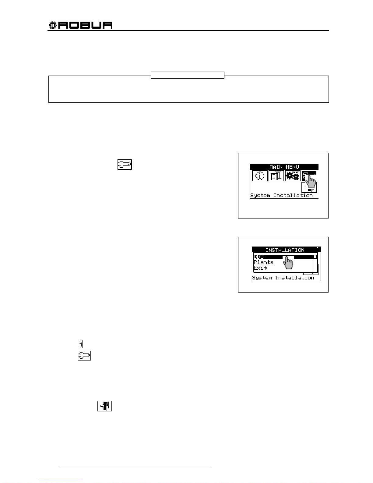
Direct Digital Controller
66 Direct Digital Controller fw 4.013 – Ed. 01/2013
pump. If more than one chiller of this type is assigned to a category, the switch off delay is the same for all the
water pumps of these boilers.
In this case the Delivery and return limit temperature and Auxiliary Regulator parameters are never present
for the "Progressive complement and substitution" mode as the "complement and substitution" operating
mode is not foreseen on cold generation plants.
Setting the parameters
For the description of the setting operations for these parameters, refer to the paragraph 4.4.2.6.4 “Regulation
parameters” on page 96 relative to setting the basic system part.
4.4 SYSTEM INSTALLATION
Only professionally qualified personnel may access this menu. To
access the menu select
from the main menu as shown in the
figure on the right, then enter, if requested, the installer password on the
numerical keypad that appears on the display.
The options available in this menu are indicated below.
4.4.1 DDC
4.4.2 PLANTS
4.4.1 DDC
To access the menu, select DDC from the drop-down menu.
4.4.1.1 Setting ID
This option allows the user to assign the ID of each Direct Digital Controller in Multi DDC plants.
For single DDC plants it is not necessary to assign an ID to the DDC, as in this case the default value of
ID=960 is assigned.
To set the ID, follow the instructions below.
1 - Select
from the initial screen to gain access to the main menu.
2 - Select
to gain access to the System installation.
3 - Enter the installer password on the numerical keypad that appears on the display.
4 - Select “DDC” from the drop-down menu.
5 - Select “Set ID” from the drop-down menu.
6 - Position the cursor on the number to the left of the text “ID value”. Press the knob: the number starts to
flash. Turn the knob to modify the value and press to confirm.
7 - To exit, select
.
8 - Repeat steps 1 to 7 for each DDC linked to the CAN BUS network and assign an ID value that is
different
from that of the other DDCs.
NOTE
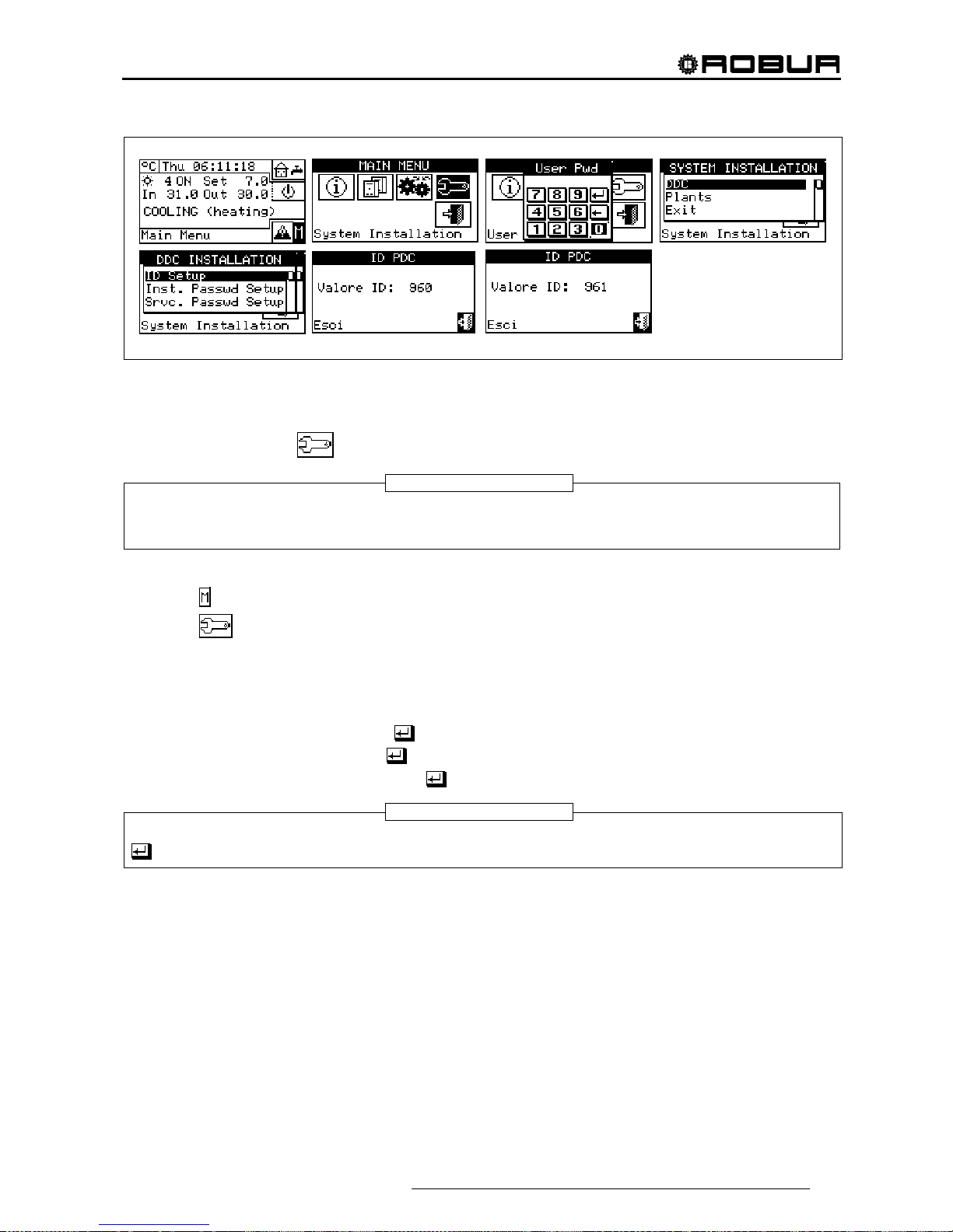
Direct Digital Controller
Direct Digital Controller fw 4.013 – Ed. 01/2013 67
4.4.1.2 Setting the installer password
This option allows the user to set/disable the installer password.
Once the password has been enabled, it is necessary to enter it in order to access:
System Installation (
);
Every time a menu is left with active password, the installer password is kept enabled for a period equal to
10 min. At the end of this period, the entering of the installer password will be required again to gain access
to one of the above-said menus.
To set or change the installation password, follow the instructions below:
1 - Select
from the initial screen to gain access to the main menu.
2 - Select
to gain access to the System installation.
3 - If required, enter the installer password on the numerical keypad shown on the display;
4 - Select “DDC” from the drop-down men u.
5 - Select “Inst. Passwd Setup” from the drop-down menu.
6 - If an installer password is already present, a numerical keypad will appear on the DDC’s screen. Enter
the old installer password and select
to confirm.
7 - Enter the new password and select
to confirm.
8 - Enter the new password again and select
to confirm.
To disable the installer password, do not enter the new password at points 7 and 8 – instead, simply select
.
NOTE
NOTE

Direct Digital Controller
68 Direct Digital Controller fw 4.013 – Ed. 01/2013
If the installation password is disabled, it is no longer necessary to enter it in order to gain access to the
following menus:
4.4.1.3 Service password setup
This option permits to set/disable the assistant’s password .
Once the password has been enabled, it is necessary to enter it in order to access to:
Modifying Set of Parameters (option present in Units management menu
);
Default Set of Parameters (option present in Units management menu
).
Every time a menu is left with active password, the assistant’s password is kept enabled for a period equal
to 10 min. At the end of this period, the entering of the assistant’s password will be required again to gain
access to one of the above-said menus.
To set or change the installation password, follow the instructions below:
1 - Select
from the initial screen to access the main menu.
2 - Select
to gain access to the System installation.
3 - If required, enter the installer password on the numerical keypad shown on the display;
4 - Select “DDC” from the drop-down menu.
5 - Select “Srvc.Passwd Setup” from the drop-down menu.
6 - If an assistant’s password is already present on the DDC screen, a numerical keypad will be shown; enter
the assistant’s old password on the numerical keypad and select
to confirm.
7 - Enter the new password and select
to confirm.
8 - Enter the new password again and select
to confirm.
To disable the Assistant’s password, do not enter the new password at steps 7 and 8, but select only .
NOTE
NOTE

Direct Digital Controller
Direct Digital Controller fw 4.013 – Ed. 01/2013 69
4.4.1.4 Machine configuration
Before performing these operations, make sure that all the built-in S61 electronic boards have been
configured, i.e. have had an ID (identifier = network address) assigned to them and have been assigned to a
plant.
Moreover, check that the correct group of belonging has been assigned to every unit: Base plant part or
Splitting plant part (see programming manual, sheet S61).
In the presence of one or more RB100 or RB200 devices, also check that they have been configured (see
“RB100 Installation and Use Booklet” Code D-LBR468 or “RB200 Installation and Use Booklet” Code DLBR632) according to the type of device used.
Finally ensure that all units and any RB100 or RB200 devices are switched on when the Direct Digital
Controller (DDC) is switched on.
Description of the screen.
Figure 17 shows an example screen from the Machine configuration menu.
Figure 17– EXAMPLE OF MACHINE CONFIGURATION MENU SCREEN
Table 5 shows all types of units and plant parts with a short description. For more information on the
management of third party units (only with RB200) and plant parts also refer to the “Installation and use
booklet for RB100 (code D-LBR468) and the “RB100 Applications Manual (code D-LBR467)”, or the
“Installation and Use Booklet for RB200” (Code D-LBR632) and “Applications Manual” (Code D-LBR630),
according to the device used.
The DDC deduces which plant or plants it must manage from the plants on which the units assigned to the
DDC itself are configured.
E
C
D
A
B
G
F
KEY:
A Unit identification number (network ID).
B Type of Robur or third party unit, or type of plant part managed by
RB100 or RB200 device(s); see Table 5
C Function of the unit or plant part; C chilled water production; H hot
water production; C/H alternate production of chilled/hot water (not for
third party units).
D Identification number of system on which the unit is installed. Letter
“S” indicates that the group to which the unit or the plant part belongs
is the separable system.
E Scroll arrows for viewing the units.
F Exit screen
G Text describing function represented by the icon highlighted by the
cursor

Direct Digital Controller
70 Direct Digital Controller fw 4.013 – Ed. 01/2013
For example, if machines that are all on the same cold plant are assigned to the DDC, it assumes that it has to
manage that cold plant.
If machines are assigned to a cold plant and to a hot plant with different IDs, the DDC assumes that it has to
manage two independent plants - one cold and one hot.
If 2-line hot/cold machines are assigned to the same plant (AYF/2 or GAHP-AR) and/or cold and hot machines
to the same plant (e.g. 1 ACF to plant with ID=0 and a GAHP-A unit to the same plant), the DDC assumes that
it has to manage one two-line hot/cold plant.
The management of two-line hot/cold plants is obtained also in the following particular cases:
AYF/4 if both modules are assigned to the same plant ID
GAHP-GS/WS if both modules are assigned to the same plant ID.
The screen of Figure 17 shows the existing units, for each one of which what follows is indicated machine ID,
machine type or plant part type, function (heating and/or cooling) and the number of the plant to which they
are assigned (letter “S” indicates that the group to which the unit belongs is the separable plant. If letter “S” is
not present beside the string that identifies the unit type, this means that the group to which the unit belongs is
the base plant).
For 4-line units (AYF/4 and GAHP-GS/WS), two consecutive rows are displayed (both with the same unit ID),
one relating to the cooling module (C), the other to the heating module (H); each row shows the number of the
plant to which that module is assigned.
For AYF/4 units it is possible to assign the modules to two different DDCs (Multi DDC plants only).
For GAHP-GS/WS units the system forces the assignment of the modules to the same DDC.
To assign the units and plant parts to the DDC, follow the instructions below:
1 - Select
from the initial screen to gain access to the main menu.
2 - Select
to gain access to the System installation.
3 - Enter the installer password on the numerical keypad that appears on the display.
4 - From the drop-down menu select “DDC”.
5 - Rotate the knob to scroll the cursor downwards until “Config Machines” is highlighted then press the
knob to access the screen.
6 - Select “Yes” to carry out a new configuration. WARNING: EACH TIME A NEW CONFIGURATION IS
PERFORMED, THE PREVIOUS CONFIGURATION IS CANCELLED.
7 - Position the cursor on
then press the knob to assign the machine and/or the deviation valves to the
plant. The symbol
points out that the unit has been assigned to the plant.
8 - Select
or to view the other units to assign to the plant or plants.
9 - Repeat the operations described in steps 7 and 8 until all the units/valves to be managed by this DDC
have been selected.
10 - To exit “Config Machines” select
.
If the plant contains at least one unit belonging to the separable group, the configuration shall be
completed following the indications provided in paragraph 4.4.2.5.1 “Heating/DHW Select” on page
87. and to paragraph 4.4.2.6.10 "Heating/DHW select" on page 119 (if at least one hot unit belonging
to the base plant is present). Omitting this step, the caption “CONFIG. INCOMPL.” (configuration
incomplete) will be shown on the main screen.
NOTE
WARNING
WARNING

Direct Digital Controller
Direct Digital Controller fw 4.013 – Ed. 01/2013 71
Direct Digital Controller
72 Direct Digital Controller fw 4.013 – Ed. 01/2013
Unit type
(code on the display)
Description
ACF All types of Robur absorption chillers in the ACF60 series
ACF-HR
All types of Robur absorption chillers with heat recuperators in the ACF60-HR
series
AY Robur 35 kW boilers in the AY119 series
AY120 Robur 35 kW condensing boilers in the AY120 series
AYF/2 Robur combined chiller ACF60 and boiler AY119 2 line
AYF/4 Robur combined chiller ACF60 and boiler AY119 4 line
PC/C ProntoClima Robur for cooling only
PC/CR Pronto Clima Robur for cooling and heating
HP-A
All types of Robur Air-Water absorption heat pumps for non-modulating heating
only, GAHP-A series
HP-W All types of Robur Air-Water non-modulating heat pumps, GAHP-W series
E3-A
All types of Robur Air-Water absorption heat pumps for modulating condensing
heating GAHP-A and E
3
-A series
E3-xS
All types of Robur Ground-Water and Water-Water absorption modulating
condensing heat pumps in the GGAHP-GS, GAHP-WS e E
3
-GS, E3-WS series
HP-AR
All types of Robur Air-Water absorption heat pumps for heating and cooling
(reversible heat pump), GAHP-AR series
PThrd Boiler or chiller produced by third parties (managed by the RB200 device(s))
Type of plant part
(code on display)
Description
VACS
Valve separating the separable plant part without limit switch contacts (managed
by RB100/RB200)
VACSF
Valve separating the separable plant part with limit switch contacts (managed by
RB100/RB200)
VC/H
Cooling/heating commutation valve without limit switch (managed by
RB100/RB200)
C/HVF Cooling/heating commutation valve with limit switch (managed by RB100/RB200)
ProbC(H)
Delivery and Return T probes for cooling or cooling/heating system. 2 lines
(managed by RB200)
ProbesH Delivery and Return T probes for heating system (managed by RB200)
ProbesSep Delivery and Return T probes for separable plant part (managed by RB200)
RtnPrbPC Return T probe for heat pump unit (managed by RB200)
Pump C(H)
Primary water pump of cooling or cooling/heating system. 2 lines (managed by
RB200)
PumpH Primary circuit water pump for heating system (managed by RB200)
PumpSep Primary circuit water pump on separable plant part (managed by RB200)
PmpC(R)S
Secondary water pump of cooling or cooling/heating system. 2 lines (managed
by RB200)
PumpHSec Secondary circuit water pump for heating system (managed by RB200)
Table 5

Direct Digital Controller
Direct Digital Controller fw 4.013 – Ed. 01/2013 73
4.4.1.5 Checking machine configuration
Via this menu, existing machine configurations may be checked.
To carry out a configuration check:
Turn the knob to position the cursor on “Units Bind.Check”, and
press the knob to access the screen.
Select
or to view all the units assigned to this DDC.
To exit, select
.
4.4.1.6 Master DDC Setup (Multi DDC plants only)
This option represents the third phase
of the Multi-DDC configuration (see paragraph 4.5.2.2 – “Multi DDC
Binding” on Page 125) and is necessary in order to define the status of each DDC (plant Master or Slave). For
a given plant, a single DDC is configured as the Master DDC while the others are configured as Slave DDCs.
To set this option, follow the instructions below:
1 - Select from the initial screen to gain access to the main menu.
2 - Select
to gain access to the System installation.
3 - Enter the installer password on the numerical keypad that appears on the display.
4 - From the drop-down menu select “DDC”.
5 - Select “Master DDC Setup” from the drop-down menu.
6 - Select the
symbol for two-line cooling/heating plants, for hot water production plants, or
for chilled water production plants.
7 - Position the cursor on
and press the knob to define the DDC as Master or Slave DDC. Th e symbol
indicates that the DDC has been defined as Master DDC, while the symbol indicates that it has been
defined as a Slave DDC. To exit, select
.
8 - If the DDC manages two plants, repeat steps 6 and 7 for the other plant.
9 - Repeat steps 1 to 7 for each DDC present.
On any one plant, only one DDC may be defined as the Master DDC.
Units belonging to different groups (Base Group and Separable Group) cannot be configured on a
Slave DDC
On a Slave DDC it is not possible to configure objects managed by RB100 device(s) (plant parts) or
RB200 (third party units and plant parts).
NOTE

Direct Digital Controller
74 Direct Digital Controller fw 4.013 – Ed. 01/2013
4.4.1.7 Multi DDC configuration
This represents the fourth stage
of the configuration of Multi DDC plants (for further information consult
Paragraph 4.5.2.2– “Multi DDC Binding”) and must be carried out with all the DDCs of the plant receiving
electrical current. The DDCs exchange information about the machine assigned to them, to determine whether
they must be co-ordinated in order to manage any units. This occurs when units, or modules of units, have
been assigned to more than one DDC, linked to the same plant.
All DDCs begin to display information about themselves and about the other DDCs present, as shown in
Figure 18. The first row shows information regarding the DDC on which data is being viewed. The following
rows regard the other DDCs present in the network. The figure below shows the parameters displayed during
configuration of Multi DDC plants.
Figure 18 – EXAMPLE OF MACHINE CONFIGURATION MENU SCREEN
For all the DDCs in the plant, carry out the following operations:
1 - Select
from the initial screen to gain access to the main menu.
2 - Select
to gain access to the System installation.
3 - Enter the installer password, if requested, on the numerical keypad that appears on the display.
4 - From the drop-down menu select “DDC”.
5 - Select “Multi DDC Binding” from the drop-down menu.
6 - Select “Yes” from the screen that appears.
7 - A screen appears on which the data described in
Figure 18 appears, regarding the DDC on which Multi
DDC configuration is being carried out.
8 - Repeat steps 1 to 7 on all other DDCs in the plant.
KEY:
A DDC identification number (network ID).
B Identification number of the chilled water production plant;
C DDC function for the plant indicated at point B: M = Master; S =
Slave.
D Identification number of the hot water production plant;
E DDC function for the plant indicated at point D: M = Master; S =
Slave.
F Scroll arrows for viewing the DDCs.
G Exit screen
H Text describing the function of the icon selected.
I The first row shows the data for the DDC on which Multi DDC
configuration is being carried out.
F
D
A
I
H
C B E
G
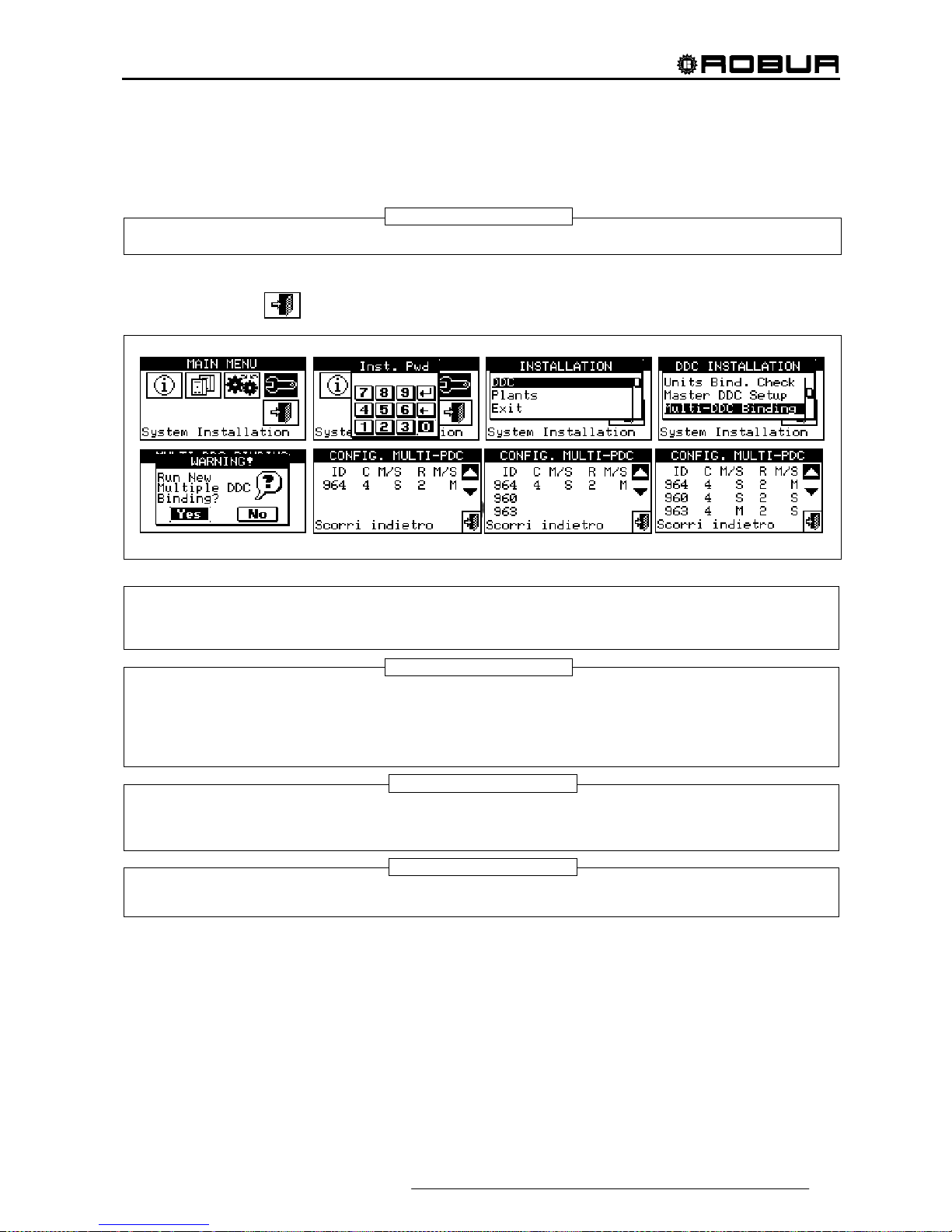
Direct Digital Controller
Direct Digital Controller fw 4.013 – Ed. 01/2013 75
9 - Wait for the DDC to receive information from the other DDCs so that all data from them is displayed: DDC
ID, number/numbers of plant/plants managed, type of plant, and indication of whether the DDC is a
Master or Slave DDC for each plant managed.
All DDC data appears on the screen only when Multi DDC configuration is accessed on all of them.
10 - Check carefully that all information shown is complete and consistent with that desired.
11 - Exit by selecting
on all the DDCs.
The Master DDC of a plant on which units of the GAHP-GS/WS type are configured MUST be one of those
that actually manage a number of GAHP-GS/WS units. (Warning: this rule must be respected by the
installation technician, and is not automatically guaranteed).
If units of the GAHP- GS/WS type are configured as 4-line units (i.e. the cold "branch" is configured on a
plant of a different number from the plant on which the hot "branch" is configured), the Master DDC of the
two plants MUST be the same. (This rule nevertheless, is "forced", because if a DDC on which units of the
GAHP- GS/WS type in 4-line mode are configured is set as Master DDC for one of two plants, it is
automatically set ALSO as Master for the other plant).
Every DDC Slave cannot have units belonging to different Groups; that is, every Slave DDC shall have only
units belonging to the Separable Group or only units belonging to the Base Group. The possibility of having
units belonging to both Groups occurs only on the Master DDC
All objects managed by one or more RB100 (plant parts) or RB200 devices (third party units and plant parts)
can only be configured on the plant Master DDC.
NOTE
NOTE 2
NOTE 3
NOTE 4
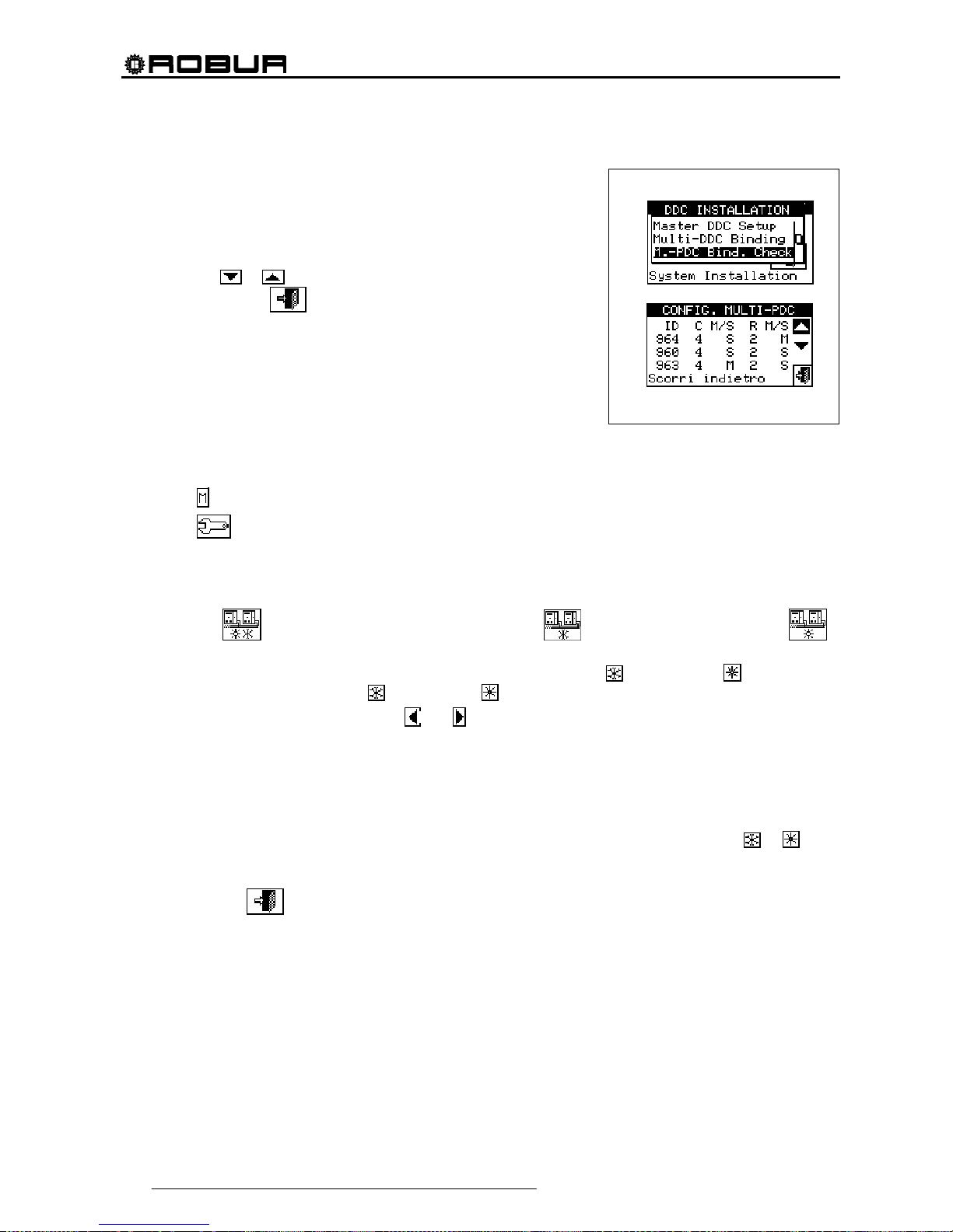
Direct Digital Controller
76 Direct Digital Controller fw 4.013 – Ed. 01/2013
4.4.1.8 Checking Multi DDC configuration
This menu allows the user to check the existing Multi DDC
configuration.
To carry out a configuration check:
1 - Turn the knob to position the cursor on “M.-PDC Bind. Check”
and press the knob to access the screen.
2 - Select
or to view all the units assigned to this DDC.
3 - To exit, select
.
4.4.1.9 Third party product category
This menus is used to set the category that third party units belong to.
1 - Select
from the initial screen to gain access to the main menu.
2 - Select
to gain access to the System installation.
3 - Enter the installer password, if requested, on the numerical keypad that appears on the display.
4 - From the drop-down menu select “DDC”.
5 - Select “Third P prod Categ" from the drop down menu and press the knob to access the screen.
6 - Select the
symbol for two-line cooling/heating plants, for hot water production plants, or
for chilled water production plants.
7 - For plants with 2-line cooling/heating, use the button with the symbol
(HEATING) or (COOLING) to
select the type of third party unit:
for BOILERS, for CHILLERS.
8 - Select the ID of a third party unit using
and .
9 - Set the category of the third party unit selected in point 8 to the required value: select the numeric value
indicating the category, press the knob and turn clockwise to increase the value, anti-clockwise to
decrease the value.
10 - Press the knob to confirm.
11 - Repeat steps 8, 9 and 10 to set the category of the other third party units of the same type.
12 - If necessary, in the case of two-line cooling/heating plants, use the button with the symbol
or again
to select the other type of third party unit and repeat steps 8, 9 and 10 to set the category of all third party
units of that type.
13 - To exit, select
.
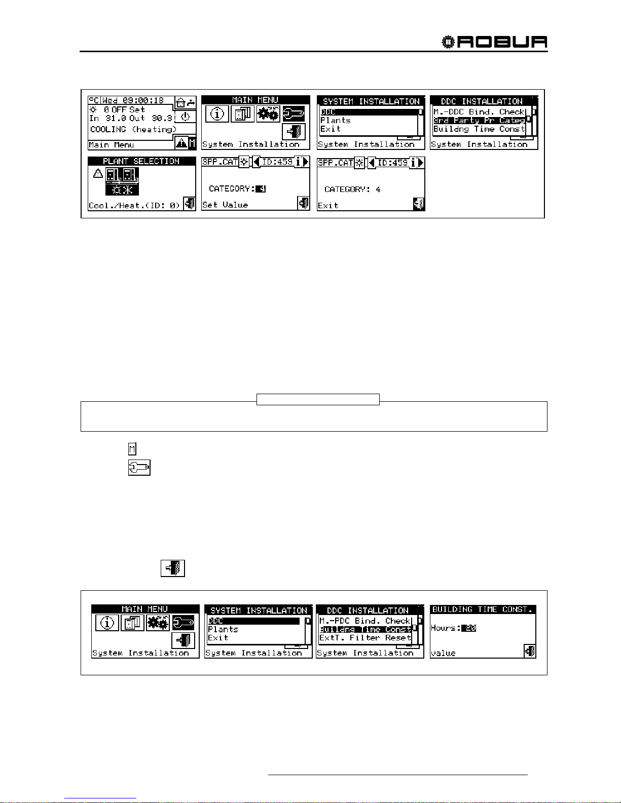
Direct Digital Controller
Direct Digital Controller fw 4.013 – Ed. 01/2013 77
4.4.1.10 Building time constant
The option allows to set the time constant of the building. This is used as a parameter of a filter that has the
purpose of dampening the external temperature variations for the temperature calculations of the water via
climatic curve.
The setting is necessary in the climatic curve and/or external temperature mode is used.
When the external temperature varies, there is a corresponding variation of the heat load and therefore to
keep the temperature constant in the rooms, the water temperature must be modified; this is carried out on the
basis of the climatic curve.
However, due to the heat capacity of the building, the variation of the heat load does not take place instantly
on variation of the external temperature, but progressively in a certain interval of time. It is therefore necessary
to progressively change the water temperature, ideally during the same interval of time.
The value that can be set for the time constant has a range from 0 to 50h with default value of 20h. This must
be set on the basis of the building time constant, e.g. it will assume the low values in the case of pre-fabricated
buildings in wood and high values in the case of traditional buildings in stone.
If the 0 value is set, the filter is disabled. Therefore, for the calculation of the water temperature via climatic
curve the instant value of the external temperature is used, instead of the filtered one.
1 - Select
from the initial screen to gain access to the main menu.
2 - Select
to gain access to the System installation.
3 - Enter the installer password, if requested, on the numerical keypad that appears on the display.
4 - From the drop-down menu select “DDC”.
5 - Select “Building Time Const.” from the drop down menu and press the knob to access the screen.
6 - To modify the data previously set, press the knob and turn it clockwise to increase the value, anti-
clockwise to decrease it.
7 - Press the knob to confirm.
8 - To exit, select
.
4.4.1.11 Reset external temperature filter
This option allows to re-initialise the external temperature filter. The values of the external filtered temperature
are placed equal to that of the instant external temperature and then the filter is re-activated.
NOTE
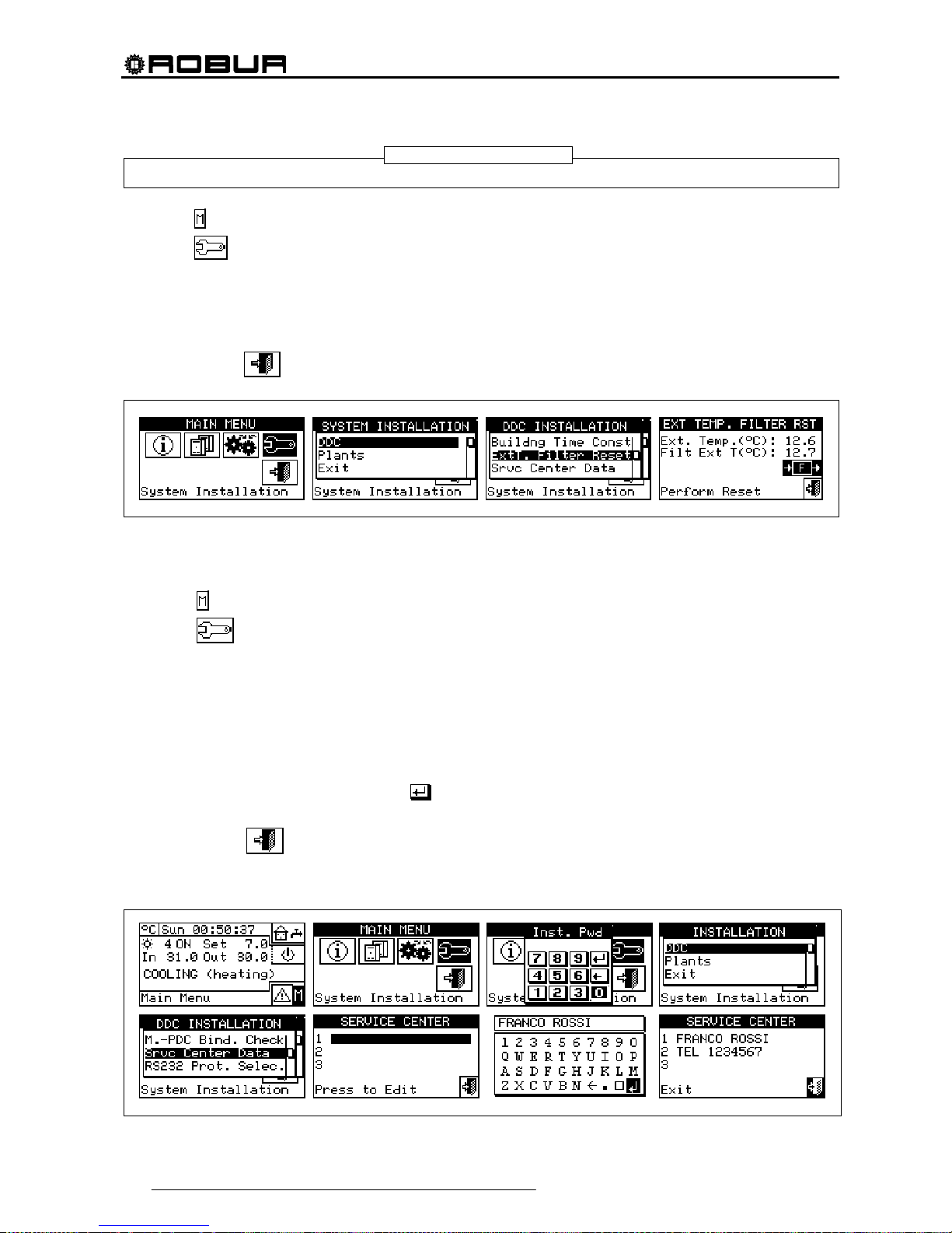
Direct Digital Controller
78 Direct Digital Controller fw 4.013 – Ed. 01/2013
It is important ALWAYS to follow this operation during the installation phase of the DDC..
1 Select
from the initial screen to gain access to the main menu.
2 Select
to gain access to the System installation.
3 Enter the installer password, if requested, on the numerical keypad that appears on the display.
4 From the drop-down menu select “DDC”.
5 Select “Ext.temp. filter res. from the drop down menu and press the knob to access the screen.
6 Press F to reset the filter.
7 To exit, select
.
4.4.1.12 Technical assistance information
This option allows the user to set the data regarding the Technical Assistance Centre to contact if necessary
via the information menu (see Paragraph 3.2.4 - “TECHNICAL”).
1 - Select
from the initial screen to gain access to the main menu.
2 - Select
to gain access to the System installation.
3 - Enter the installer password on the numerical keypad that appears on the display.
4 - From the drop-down menu select “DDC”.
5 - Turn the knob to scroll the cursor downwards until “Service Centre Data” is selected and press the knob to
access the screen.
6 - To modify the data that will then be displayed in the information menu (3.2.4 - “TECHNICAL”), turn the
knob to position the cursor on the row to be modified.
7 - Press the knob: a numerical keypad appears that allows up to 18 characters to be entered.
8 - When the text has been entered, select to confirm and exit.
9 - Repeat the operations described above to enter the other two rows.
10 - To exit, select
.
NOTE

Direct Digital Controller
Direct Digital Controller fw 4.013 – Ed. 01/2013 79
4.4.1.13 Communication protocol selection
This option is used to set up the communication protocol that the DDC uses on the RS-232 and RS-485 serial
connection port.
As far as the RS-232 port is concerned, "PC Terminal” can be chosen if a link exists with a Personal Computer
provided with terminal emulation software. With this it is possible to give pre-set commands with the keyboard
and view the results on the terminal; if you select the Modbus RTU (v1.0 or v2.0) protocol, you will be able to
connect any appropriately configured Modbus Master to the DDC for data exchange (the DDC always works
as Modbus Slave), using this protocol (the difference between Modbus v1.0 and v2.0 concerns the mapping of
the Modbus logs; normally the most recent version is used (v2.0), however v1.0 is maintained for a question of
compatibility with older devices).
As far as the RS-485 port is concerned, the “PC Terminal” option is not available, while options Modbus v1.0
and v2.0 are available.
It is not possible to select a Modbus option for both ports: if a Modbus option is chosen for the RS-232 port,
the OFF option (no protocol) is automatically forced on the RS-485 port; on the other hand, selecting a
Modbus option for the RS-485 port, the “PC Terminal” option is forced for the RS-232 port.
The document describing the mapping and meaning of the Modbus logs implemented on the DDC is
available on request.
1 - Select
from the initial screen to gain access to the main menu.
2 - Select
to gain access to the System installation.
3 - Enter the installer password on the numerical keypad that appears on the display.
4 - From the drop-down menu select “DDC”.
5 - Turn the knob to scroll the cursor downward until "Select Communic. prot" is highlighted and press the
knob to access the screen.
6 - Select the required entry in the left column for RS-232, and in the right column for RS-485; for example:
• Select “PC Terminal” in the left column (RS-232) if you wish to communicate with a Personal
Computer with a terminal emulator, for example to download the events log. Select this also if you
must update the DDC software (operation reserved for authorised Technica l A ssistance Centres)
• Select a Modbus option (typically, Modbus v2.0) in the left or right column, if using a Master Modbus
connected respectively to the RS-2 32 or RS-485 port of the DDC. Robur WISE and Robur Monitor
devices require Modbus V2.0 to be set in the left column (RS-232)
4.4.1.14 Modbus address setting
This option permits to set the Modbus address, that is the address used by the DDC to answer the requests
coming from the Master Modbus. Please note that the DDC operates as a slave modbus . This has nothing to
do with the concept of Master and Slave between several DDC’s located on the same CAN; to all intents any
effect, the DDC can be either Master or Slave for the control of its unit on the plant.
NOTE
NOTE

Direct Digital Controller
80 Direct Digital Controller fw 4.013 – Ed. 01/2013
The default value is 1 and usually it doesn't need changing, except for links with bus RS-485 instead of RS232 In case of bus RS-485, in fact, there can be more DDC’s linked on the same bus and, to address them,
different addresses shall be set. In case of bus RS-232 only one DDC can be linked to the Master modbus,
therefore the default value can be left.
The address can be set with values from 1 to 247.
1 - Select
from the initial screen to gain access to the main menu.
2 - Select
to gain access to the System installation.
3 - Enter the installer password on the numerical keypad that appears on the display.
4 - From the drop-down menu select “DDC”.
5 - Turn the knob to scroll the cursor downward until highlighting “Modbus addr. Setup” and press the knob
to gain access to the screen.
6 - Select the desired address.
4.4.1.15 Com Modbus parameters
This option permits to set the parameters of the Modbus communication.
In particular, communication speed, number of data bits, stop bits and parity check can be set. The choice is
limited to 6 possible combinations:
a) 19.200 baud, 8 data bits, 1 stop bit, no parity (9600 8N1)
b) 19.200 baud, 8 data bits, 1 stop bit, pair parity (9600 8E1)
c) 19.200 baud, 8 data bits, 2 stop bits, no parity (9600 8N2) (not available on RS-485)
d) 9.600 baud, 8 data bits, 1 stop bit, no parity (9600 8N1)
e) 9.600 baud, 8 data bits, 1 stop bit, pair parity (9600 8E1)
f) 9.600 baud, 8 data bits, 2 stop bits, no parity (9600 8N2) (not available on RS-485)
Choose the desired combination, that must correspond to the setting on the Master Modbus device connected
to the DDC.
1 - Select
from the initial screen to gain access to the main menu.
2 - Select
to gain access to the System installation.
3 - Enter the installer password on the numerical keypad that appears on the display.
4 - From the drop-down menu select “DDC”.
5 - Turn the knob to scroll the cursor downwards until “Modbus.Com. Param.” is selected, and press the
knob to access the screen.
6 - Select the desired communication parameters.

Direct Digital Controller
Direct Digital Controller fw 4.013 – Ed. 01/2013 81
4.4.1.16 Erase alarms Log (for authorised Technical Assistance Centres only)
Allows the event history to be completely deleted without the need to perform a general DDC reset.
4.4.1.17 Factory defaults
This option allows the user to reset the DDC to its default factory settings. All settable parameters are returned
to their default values.
To carry out a DDC reset, follow the instructions below:
1 - Select
from the initial screen to gain access to the main menu.
2 - Select
to gain access to the System installation.
3 - Enter the installer password on the numerical keypad that appears on the display.
4 - From the drop-down menu select “DDC”.
5 - Turn the knob to scroll the cursor downwards until “Factory defaults” is selected and press the knob to
access the screen.
6 - Select “YES” to confirm the reset, “NO” to return to the drop-down menu.
This function causes also the loss of machine configuration, Multi DDC configuration and event
history.
A short message appears on the screen to confirm that the operation has been performed successfully.
NOTE
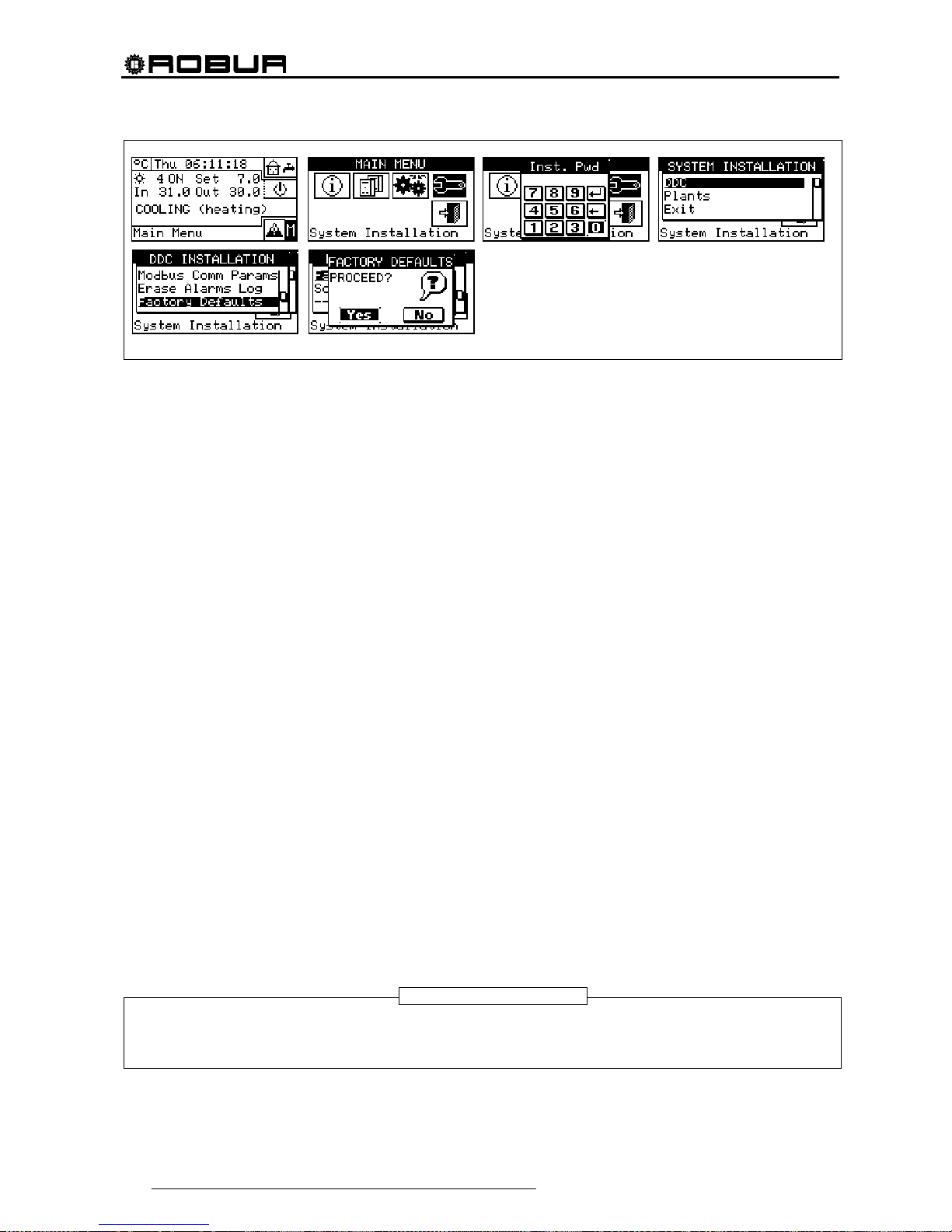
Direct Digital Controller
82 Direct Digital Controller fw 4.013 – Ed. 01/2013
4.4.1.18 Software Update (for authorised Technical Assistance Centres only)
By connecting to the Personal Computer, this updates the DDC software. The operation may be carried out
only by qualified ROBUR personnel or authorised Technical Assistance Centres.
4.4.2 PLANTS
Select “Plants” from the drop-down menu, then select the plant. The options available in this menu a re:
4.4.2.1 BUS access setup
4.4.2.2 Water pump mode (Master DDC only)
4.4.2.3 Partial operation mode (Master DDC of Multi DDC plants only)
4.4.2.4 Alarm output setup
4.4.2.5 Split plant part
4.4.2.6 Base plant part
4.4.2.1 BUS access setup
It permits to enable the access by bus to the plant control and to the possibility of modifying the plant operation
parameters.
Enabling the plant control allows you to operate the On/Off commands, invert the Cooling/Heating and change
the GAHP-GS/WS priorities, in two different ways.
Enabling the modification of functioning parameters allows you to operate on set point, differential, and
general water T timer cycle.
The foreseen control options are two:
- BMS control (Building Management System)
- Remote Assistance Control (RM)
These options can be set separately for every plant and they exclude each other.
On the contrary, the parameter access option is unique and it makes no difference between BMS and RM.
BMS plant control
By selecting “Control BMS plant” via the bus it is possible to switch the plant on and off, invert the hot and cold
(in 2-line hot/cold plants), and with 4-line GAHP-GS/WS units, change the switch on priorities, with the rules
laid down for Building Management Systems (BMS).
The procedures are as follows:
• as concerns the switching on/off, a new switch is added in series to the already existing ones. The
status of this switch can be varied only by BMS. The switching on of the plant is carried out only if all
the switches are ON (closed) (see Figure 20 page 108).
Do not enable the BMS control if the switching on/off is not effectively managed via bus; the
additional switch status is initially OFF, so if the switch is not managed it is not possible to switch
the plant on.
WARNING
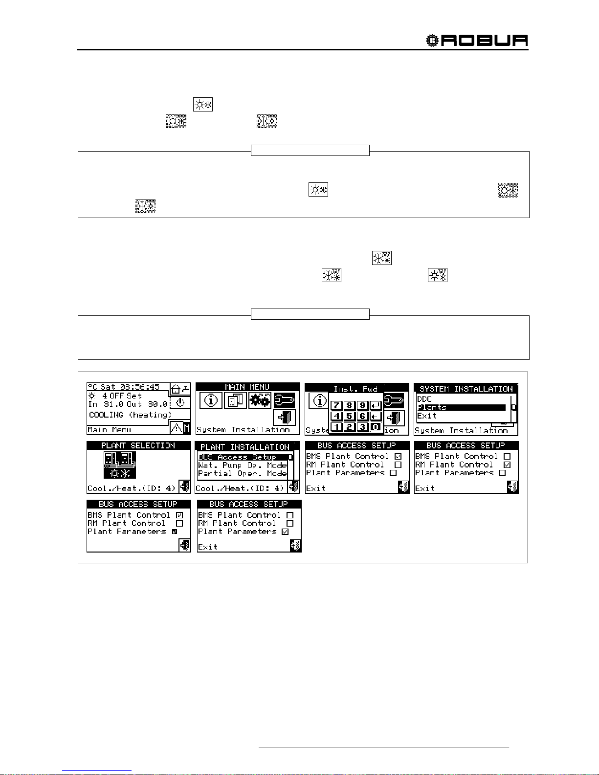
Direct Digital Controller
Direct Digital Controller fw 4.013 – Ed. 01/2013 83
• as far as cold/hot inversion is concerned, enabling the BMS control allows this to be controlled via bus,
rather than by the
button on the Plant Control Panel. This button is therefore disabled and
appears thus
(cooling) or thus (heating) according to the commands given via bus.
The YWAuto consent configuration however has priority over the BMS control, so if both are
enabled, the system manages the hot/cold inversion using the RW and RY contacts and ignores
the requests from the BMS. Also in this case, the
button is disabled and appears thus
(cooling) or
(heating) according to the commands given by the contacts.
• as concerns the change of heating/cooling operation priority of the GAHP-GS/WS modules, the choice
can be carried out with no difference either by DDC (see paragraph 2.4 "COOLING/HEATING
SERVICE ” on page 11) or by BMS; in this latter case the
button will get the appearance
corresponding to the choice made by the BMS (
priority to cooling; priority to heating
mode).
If the cooling operation is set as priority, the GAHP-GS/WS modules can be switched on by the
conditioning plant regulator, but not by the heating plant regulator; vice versa if the heating
operation is set as priority.
RM plant control
By selecting “RM plant control” it is possible to carry out the same operations available for the previous option,
but with the procedures foreseen for the Remote Assistance (RM) and that essentially consist in ensuring the
possibility of having remote controls that already exists on the DDC, managing them in the equal way.
In this case, all the plant control option can be carried out with no difference by DDC or by RM.
Plant on/ff, hot/cold inversion and setting of operating priorities for the GAHP-GS/WS units can therefore by
done by DDC (see paragraph 2.4 “COOLING/HEATING
SERVICE ” on page 11) or via bus; when a
command is sent via bus, the corresponding button will take on the appearance corresponding to the setting
made via bus.
NOTE
NOTE

Direct Digital Controller
84 Direct Digital Controller fw 4.013 – Ed. 01/2013
The YWAuto consent configuration however has priority over the RM control, so if both are
enabled, the system manages the hot/cold inversion using the RW and RY contacts and ignores
the requests from the RM system. In this case, the
button is disabled and appears thus
(cooling) or
(heating) according to the commands given by the contacts.
After enabling the RM control, if the consent configuration inhibits the global On/Off switch, this
control will be shown in reading-only mode on the DDC but it can be modified by remote
assistance, therefore operating on the plant consent.
Plant parameters
By selecting “Plant parameters” it is possible to set via bus the set point, differential, general T timer cycles via
bus, via BMS or RM.
4.4.2.2 Water pump mode (Master DDC only)
This option, in the “System installation”, allows the management mode of the water pump(s) installed on the
plant/plants to be defined.
Two operating modes are available:
Common water pump: in this case a single water pump is installed for the plant; the water flow
circulating in the plant is always the same.
Independent water pump: in this case a water pump is installed for each unit; the total number of water
pumps is the same as the number of units installed. In this case the water flow circulating in the plant is a
function of the number of units that are on.(Each water pump is on when the corresponding unit is on).
To set “Water pump mode”, follow the instructions below:
1 - Select
from the initial screen to gain access to the main menu.
2 - Select
to gain access to the System installation.
3 - Enter the installer password, if requested, on the numerical keypad that appears on the display.
4 - Select “Plants” from the drop-down menu.
5 - Select the
symbol for two-line cooling/heating plants, for hot water production plants, or
for chilled water production plants.
6 - Turn the knob to scro ll the cu rsor do wnwards until “Wat.Pump Op.Mode” is selected, and press the knob
to access the screen.
7 - Position the cursor on
next to the option to be set (Plant Single Pump or Unit Pumps) and press the
knob to make the selection. The symbol indicates that the option has been enabled .
8 - To exit, select
.
NOTE

Direct Digital Controller
Direct Digital Controller fw 4.013 – Ed. 01/2013 85
Repeat steps 5 to 8 for the second plant if the DDC is the Master DDC for two plants. In this case the two
plants can have different settings.
4.4.2.3 Partial operation mode (Master DDC of Multi DDC plants only)
This option allows the user to select the control mode for switching on the units if one or more Slave DDCs are
off.
Two choices are possible:
Disable the operation of the whole plant if one or more Slave DDCs are off (option disabled);
Allow operation of the part of the plant that is controllable if one or more Slave DDCs are off (option
enabled).
If the Master DDC is off, the whole plant is deactivated.
To set “Partial operation Mode”, follow the instructions below:
1 - Select
from the initial screen to gain access to the main menu.
2 - Select
to gain access to the System installation.
3 - Enter the installer password, if requested, on the numerical keypad that appears on the display.
4 - Select “Plants” from the drop-down menu.
5 - Select the
symbol for two-line cooling/heating plants, for hot water production plants, or
for chilled water production plants.
6 - Turn the knob to scroll the cursor downwards until “Partial operation mode” is selected and press the
knob to access the screen.
7 - Position the cursor on
and press the knob to make the selection. The symbol indicates that the
option has been enabled (the partial plant operates also when the Slave DDCs are off).
8 - To exit, select
.
Repeat steps 5 to 8 for the second plant if the DDC is the Master DDC for two plants. In this case the two
plants can have different settings.
NOTE
NOTE
NOTE

Direct Digital Controller
86 Direct Digital Controller fw 4.013 – Ed. 01/2013
4.4.2.4 Alarm output setup
On the rear of the Direct Digital Controller there is a clean contact to send an external signal if errors have
occurred in any machines (see detail “B” Figure 13 on page 54). The DDC allows one of the following options
to be set:
Disable the signal output in the event of alarm;
Enable the sending of a signal for any type of alarm;
Enable the sending of a signal only in the event of “Temperature alarms” (Master DDC only).
To configure one of the options described above, follow the instructions below:
1 - Select
from the initial screen to gain access to the main menu.
2 - Select
to gain access to the System installation.
3 - Enter the installer password on the numerical keypad that appears on the display.
4 - Select “Plants” from the drop-down menu.
5 - Select the plant for which the alarm output is to be set:
for two-line cooling/heating plant; for
the hot water production plant;
for the chilled water production plant.
6 - Turn the knob to scroll the cursor downwards until “Alarms Outp. Setup” is selected and press the knob
to access the screen.
7 - Position the cursor on
next to the option to be set (Disabled, Any alarm, Water temp. alarm).
8 - Press the knob to activate the option. The
symbol indicates that the option has been enabled .
9 - To exit, select
.
Repeat steps 5 to 9 for the second plant if the DDC manages two plants.
If the alarm output is enabled for 2 separate plants managed by the DDC, the contact trips if an alarm
condition is present in at least one of the two plants.
NOTE 2
NOTE 1
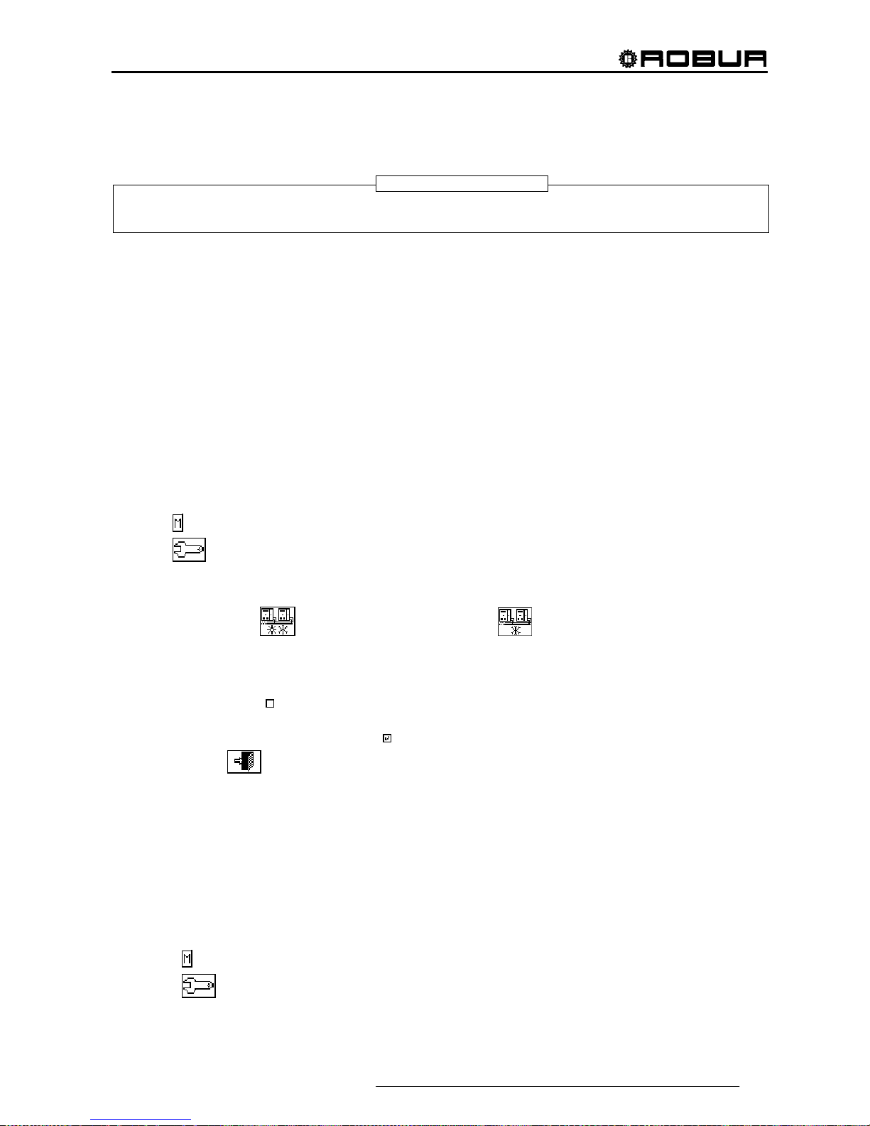
Direct Digital Controller
Direct Digital Controller fw 4.013 – Ed. 01/2013 87
4.4.2.5 Split plant part
By means of this menu the separable plant operation parameters can be controlled.
The term “Separable plant” means the plant part that can be separated from the base plant by means of
valves) and that can operate independently to provide the DHW service.
The options available in this menu are:
4.4.2.5.1 Heating/DHW Select
4.4.2.5.2 Set point range
4.4.2.5.3 Water Differential
4.4.2.5.4 Regulation parameters
4.4.2.5.5 Robur Box water pumps delay
4.4.2.5.6 Switching-over step timing
4.4.2.5.7 Splitting valve parameters
4.4.2.5.1 Heating/DHW Select
By means of this sub-menu item, it is possible to choose whether use is made of the machines configured on
the separable plant to produce DHW only (domestic hot water) or to produce (not at the same time) hot water
for the heating plant and DHW (domestic hot water). The latter function allows the units belonging to this part
of the plant (Separable part) to complement the production of hot water for heating purposes if no request for
DHW is present, or to produce domestic hot water if a request of this type is received. The production of
domestic hot water has priority over the request for heating.
1 - Select
from the initial screen to gain access to the main menu.
2 - Select
to gain access to the System installation.
3 - Enter the installer password on the numerical keypad that appears on the display.
4 - Select “Plants” from the drop-down menu.
5 - Select the plant type:
for two-line cooling/heating plant; for hot water production plant.
6 - Turn the knob to scroll the cursor downward until highlighting “Splitt.Plant Part” and press the knob to gain
access to the screen.
7 - Select “Heating/DHW select.”.
8 - Position the cursor on
next to the option that is to be set:”Heating and DHW (Alternate Service )” or “DHW
only”.
9 - Press the knob to activate the option. The
symbol indicates that the option has been enabled .
10 - To exit, select
.
4.4.2.5.2 Set point range
This option permits to define the set point temperature limit (delivery) of the separable plant for the
production of DHW. Then, the set point temperature will be set in the ”User settings” menu, if on the RB100 or
RB200 interface the following option is set: “Digital with set point DDC”; or acquired from Robur Box (RB100 or
RB200). In particular, it is possible to define the maximum water temperature for the production of domestic
hot water in the range from 5 ÷ 95°C (41÷203° F). For instance, if for a domestic hot water production plant the
set point limit value is 60°C (140° F), the user can choose a set point value ranging from 5 °C (41° F) to 60°C
(140° F).
Instructions for modifying the set point limits follow:
1 - Select
from the initial screen to access the main menu.
2 - Select
to access the “installation menu”.
3 - Enter the installer password on the numerical keypad that appears on the display.
NOTE

Direct Digital Controller
88 Direct Digital Controller fw 4.013 – Ed. 01/2013
4 - Select “Plants” from the drop-down menu.
5 - Select
for two-line cooling/heating plants, for hot water production plants.
6 - Turn the knob to scroll the cursor downward until highlighting “Splitt.Plant Part” and press the knob.
7 - Turn the knob to scroll the cursor downwards until “Set point Range” is selected, and press the knob to
access the screen.
8 - Position the cursor on the temperature value to be modified.
9 - Press the knob to allow the change of the selected value.
10 - Turn the knob to modify the value.
11 - Press the knob to confirm the set value.
12 - To exit, select
.
If the DDC is the Master DDC for two plants, repeat steps 5 to 9 for the second plant.
4.4.2.5.3 Water Differential
The screen shows the differential set on the set point temperature of the
separable plant for the production of DHW.
Configuration of differential
To set the value or values of the differential, proceed as follows.
1 - Select
from the initial screen to gain access to the main menu.
2 - Select
to gain access to the System installation.
3 - If required, enter the installer password on the numerical keypad that appears on the display.
4 - Select “Plants” from the drop-down menu.
5
- Select the plant for which the differential is to be set: for two-line cooling/heating plant; for
the hot water production plant;
6 - Turn the knob to scroll the cursor downward until highlighting “Splitt.Plant Part” and press the knob.
7 - Select “Wat.Differential” from the drop-down menu.
NOTE

Direct Digital Controller
Direct Digital Controller fw 4.013 – Ed. 01/2013 89
8 - Position the cursor on the differential value to be modified.
9 - Press the knob to allow the change of the selected value.
10 - Turn the knob to modify the value.
11 - Press the knob to confirm the set value.
12 - To exit, select
.
4.4.2.5.4 Regulation parameters
Setting of the regulation parameters
To set, proceed as described below:
1 - Select
from the initial screen to gain access to the main menu.
2 - Select
to gain access to the System installation.
3 - If required, enter the installer password on the numerical keypad that appears on the display.
4 - Select “Plants” from the drop-down menu.
5 - Select the system for which the parameters are to be set:
for two-line cooling/heating plant;
for the hot water production plant;
6 - Turn the knob to scroll the cursor downward until highlighting “Splitt.Plant Part” and press the knob.
7 - Only for two-line hot/cold systems:
8 - The display shows “Carry out semi-automatic configuration?”
9 - If you select “Yes” (normally advised) the display shows “AUTOM. CONFIGURATION enable/disable
integrals”; the DDC automatically calculated for all machine categories the most appropriate values of the
two parameters “enable integral” and “disable integral” according to the values set for the others. The
value is calculated and set when you exit the panel.
10 -
If you select “No” the display shows “MANUAL configuration of enable/disable integrals.”; the DDC
DOES NOT automatically calculate the two parameters “Enable integral” and “Disable integral”. Use this
option if you wish to set the two parameters manually, of to see the values set automatically by the DDC
following previous access to the panel.
11 - Select the category of the machines for which the regulation parameters are to be set using the
and
buttons. Only the categories to which the machines effectively present on the system belong are
proposed.
12 - Choose the page in which the first value to be edited is present, using the buttons
, or , ,
(the number on the left on the button indicates the current page, the one on the right the total number of
pages available).
13 - To modify the values set, position the cursor on the value to be modified.
14 - Press the knob to allow the change of the selected value.
15 - Turn the knob until the desired value is displayed.
16 - Press the knob to confirm the set value.

Direct Digital Controller
90 Direct Digital Controller fw 4.013 – Ed. 01/2013
17 - If necessary repeat steps 12 - 17 -to complete the parameter settings for the selected category; then,
again if necessary, set the parameters of other categories, executing step 11 - and steps 12 - 17 - again.
18 - To exit, select
.
4.4.2.5.5 Robur Box water pumps delay
This parameter is used to set the switch-off delay on the common primary water pump on the separable plant
part, when managed by RB200; if the water pump is not configured, access to the parameter settings panel is
denied.
1 - Select
from the initial screen to gain access to the main menu.
2 - Select
to gain access to the System installation.
3 - If required, enter the instal ler password on the numerical keypad that appears on the display.
4 - Select “Plants” fro m the drop-down menu.
5 - Select the system for which the parameters are to be set:
for two-line cooling/heating plant;
for the hot water production plant;
6 - Turn the knob to scroll the cursor downward until highlighting “Splitt.Plant Part” and press the knob.
7 - Select “RBox W Pump Delay” from the drop-down menu.
8 - To modify the values set, position the cursor on the value to be modified.
9 - Press the knob to allow the change of the selected value.
10 - Turn the knob until the desired value is displayed.
11 - Press the knob to confirm the set value.
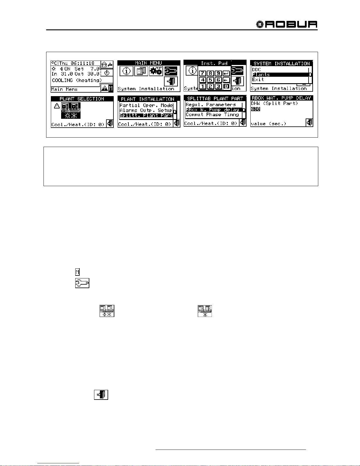
Direct Digital Controller
Direct Digital Controller fw 4.013 – Ed. 01/2013 91
RB100/RB200
Take care not to confuse this parameter with the "Water pump delay" parameters which may be present in
the regulation parameter settings panel of various categories of units (see Third party boiler water pump
delay on page 63 and Third party chiller water pump delay on page 65): these parameters are in fact used to
set the switch-off delay of water pumps dedicated to third party units, if present and controlled by the Robur
system.
4.4.2.5.6 Switching-over step timing
This option permits to set the values concerning the times to be met during the switching-over step of the
three-way deviation valves that separate the separable plant from the base plant. In particular what follows
shall be set:
- Mach. time OFF: indicating the time in which the machine are off while the valves are switching over
(used during both the separation step and the inclusion to the base plant);
- Average insert. add. delay of sep. plant. (inclusion phase): indicating how much time shall elapse
after the inclusion step of the separable group units to the base plant, in order to consider the
delivery and return temperature of the machine just included in the total average value of the plant.
To set above-said value, operate as described below:
1 - Select
from the initial screen to gain access to the main menu.
2 - Select
to gain access to the System installation.
3 - If required, enter the installer password on the numerical keypad that appears on the display.
4 - Select “Plants” from the drop-down menu.
5 - Select the plant:
for two-line cooling/heating plant; for the hot water production plant;
6 - Turn the knob to scroll the cursor downward until highlighting “Splitt.Plant Part” and press the knob.
7 - Turn the knob to scroll the cursor downward until highlighting “Commut.Phase Timng” and press the
knob.
8 - Place the cursor on the value to be edited; the value is expressed in seconds.
9 - “Units OFF time” can be set between 0 and 600 seconds.“Split Plt Added To Avg Addit.
10 - Delay” can be set from 0 to 300 seconds.
11 - Press the knob to allow the change of the selected value.
12 - Turn the knob to modify the value.
13 - Press the knob to confirm the set value.
14 - To exit, select
.

Direct Digital Controller
92 Direct Digital Controller fw 4.013 – Ed. 01/2013
4.4.2.5.7 Splitting valve parameters
This parameter shall be set only in case use is made of three-way deviation valves for the separation of the
separable group units provided with auxiliary limit switch contacts.
This parameter indicates the maximum time that the three-way valves can take to switch over from one
position to the other. Shouldn’t the valve reach the preset limit switch within this time, an error is generated (for
further information see error list).
To set above-said value, operate as described below:
1 - Select
from the initial screen to gain access to the main menu.
2 - Select
to gain access to the System installation.
3 - If required, enter the installer password on the numerical keypad that appears on the display.
4 - Select “Plants” from the drop-down menu.
5 - Select the plant:
for two-line cooling/heating plant; for the hot water production plant;
6 - Turn the knob to scroll the cursor downward until highlighting “Splitt.Plant Part” and press the knob.
7 - Turn the knob to scroll the cursor downward until highlighting “Splitting. Vlv Prms” and press the knob.
8 - Place the cursor on the value to be edited; the value is expressed in seconds (from 0 to 600 secs.).
9 - Press the knob to allow the change of the selected value.
10 - Turn the knob to modify the value.
11 - Press the knob to confirm the set value.
12 - To exit, select
.

Direct Digital Controller
Direct Digital Controller fw 4.013 – Ed. 01/2013 93
4.4.2.6 Base plant part
By means of this menu it is possible to set the operation parameters of the base plant.
The term “Base plant” means the plant part containing all the units, excluding the ones that can be
separated from the same plant.
The options available in this menu are:
4.4.2.6.1 Water Differential
4.4.2.6.2 Auxiliary boiler operation
4.4.2.6.3 Rated plant power
4.4.2.6.4 Regulation parameters
4.4.2.6.5 RoburBox water pump delay
4.4.2.6.6 Units use priority (Master DDC of plants with GAHP- GS/WS only)
4.4.2.6.7 Temperature Alarm Setup (Master DDC only)
4.4.2.6.8 Cool/Heating inversion valve parameters
4.4.2.6.9 Cooling/heating service configuration
4.4.2.6.10 Heating/DHW select
4.4.2.6.11 Base DHW service configuration
4.4.2.6.1 Water Differential
The screen shows the differential set on the set point temperature. The
figure contains the value for a chilled water production plant.
Configuration of differential
To set the value or values of the differential, proceed as follows.
1 - Select
from the initial screen to gain access to the main menu.
2 - Select
to gain access to the System installation.
3 - If required, enter the installer password on the numerical keypad that appears on the display.
4 - Select “Plants” from the drop-down menu.
5 - Select the plant for which the differential is to be set:
for two-line cooling/heating plants, for
hot water production plants, or
for chilled water production plants.
6 - Turn the knob to scroll the cursor downward until highlighting “Base plant part” and press the knob.
7 - Select “Wat.Differential” from the drop-down menu.
8 - Place the cursor on the differential value to be modified: for “cold only” plants
only the value of the
cooling differential will appear (Condit); for the “hot only” plants
only the value of the heating
differential will appear (Heating), for the two-line hot/cold plants
the values of both heating and
cooling differentials will appear (Condit. and Heating).
9 - Press the knob to allow the change of the selected value.
10 - Turn the knob to modify the value.
11 - Press the knob to confirm the set value.
NOTE
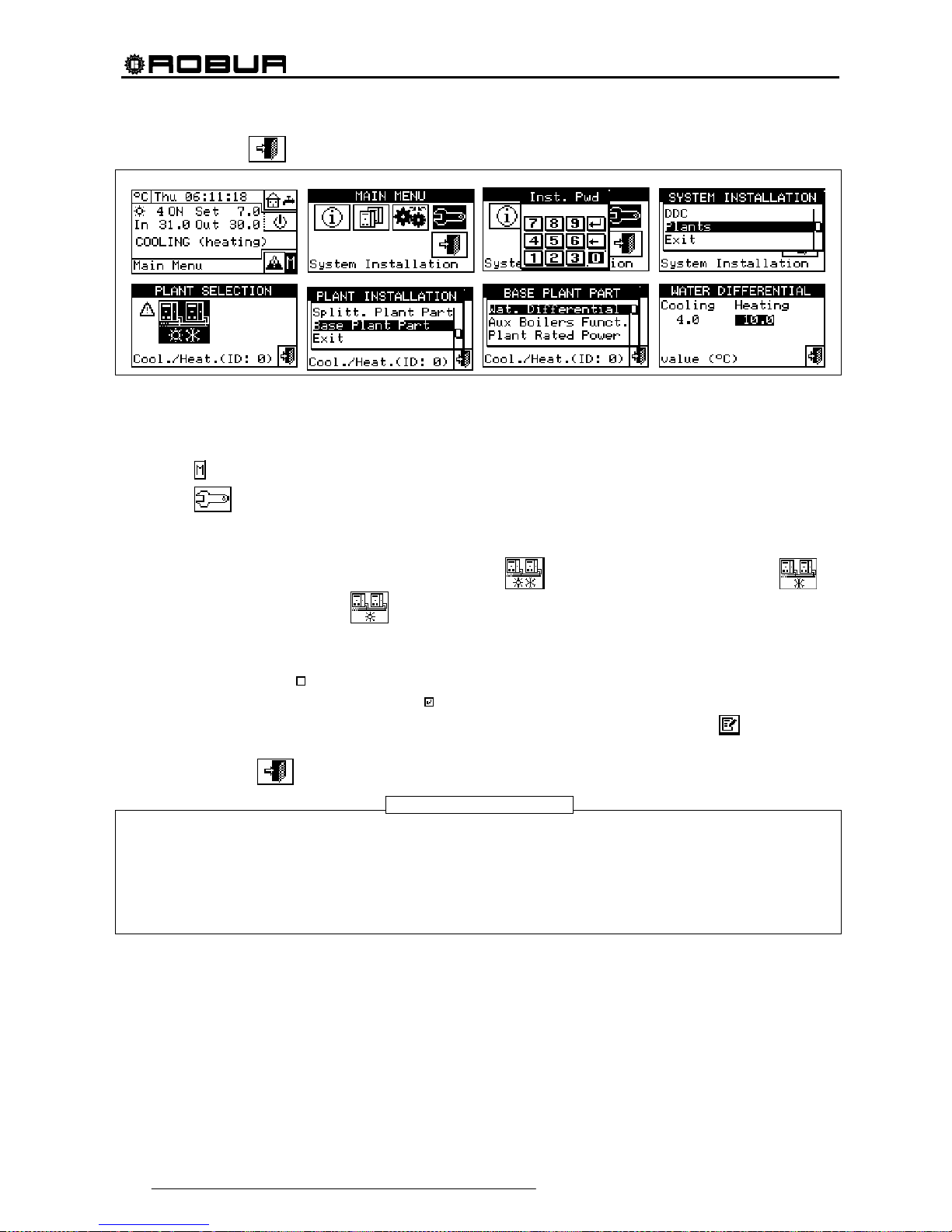
Direct Digital Controller
94 Direct Digital Controller fw 4.013 – Ed. 01/2013
12 - To exit, select .
4.4.2.6.2 Auxiliary boiler operation
To set the operating modes of the auxiliary boilers (only in heating or 2-line cooling/heating plant) proceed as
described below; for more information on the topic see paragraph 4.2 on page 55. and the Applications
Manual (code D-LBR630).
1 - Select
from the initial screen to gain access to the main menu.
2 - Select
to gain access to the System installation.
3 - If required, enter the instal ler password on the numerical keypad that appears on the display.
4 - Select “Plants” fro m the drop-down menu.
5 - Select the plant for which the differential is to be set:
for two-line cooling/heating plants, for
hot water production plants, or
for chilled water production plants.
6 - Turn the knob to scroll the cursor downward until highlighting “Base plant part” and press the knob.
7 - Select "Auxil. boiler operation" from the drop-down menu.
8 - Position the cursor on
next to the option that is to be set: "Complement" or "Complem.& Substit".
9 - Press the knob to activate the option. The
symbol indicates that the option has been enabled .
10 - When the “Complem. & Substit.” function is enabled the display shows the symbol
, selecting and
pressing the knob we can enable the “Progressive substitution” function.
11 - To exit, select
.
Selecting "Progressive substitution" also required:
• Special plant configuration.
• The presence of an additional temperature probe on the return manifold of the heat pump.
• The setting of additional parameters in the regulation parameter settings panel (see 4.4.2.6.4 on
page 96).
Discuss the applicability of this option with the Robur Pre-Sales Service, before using it.
WARNING
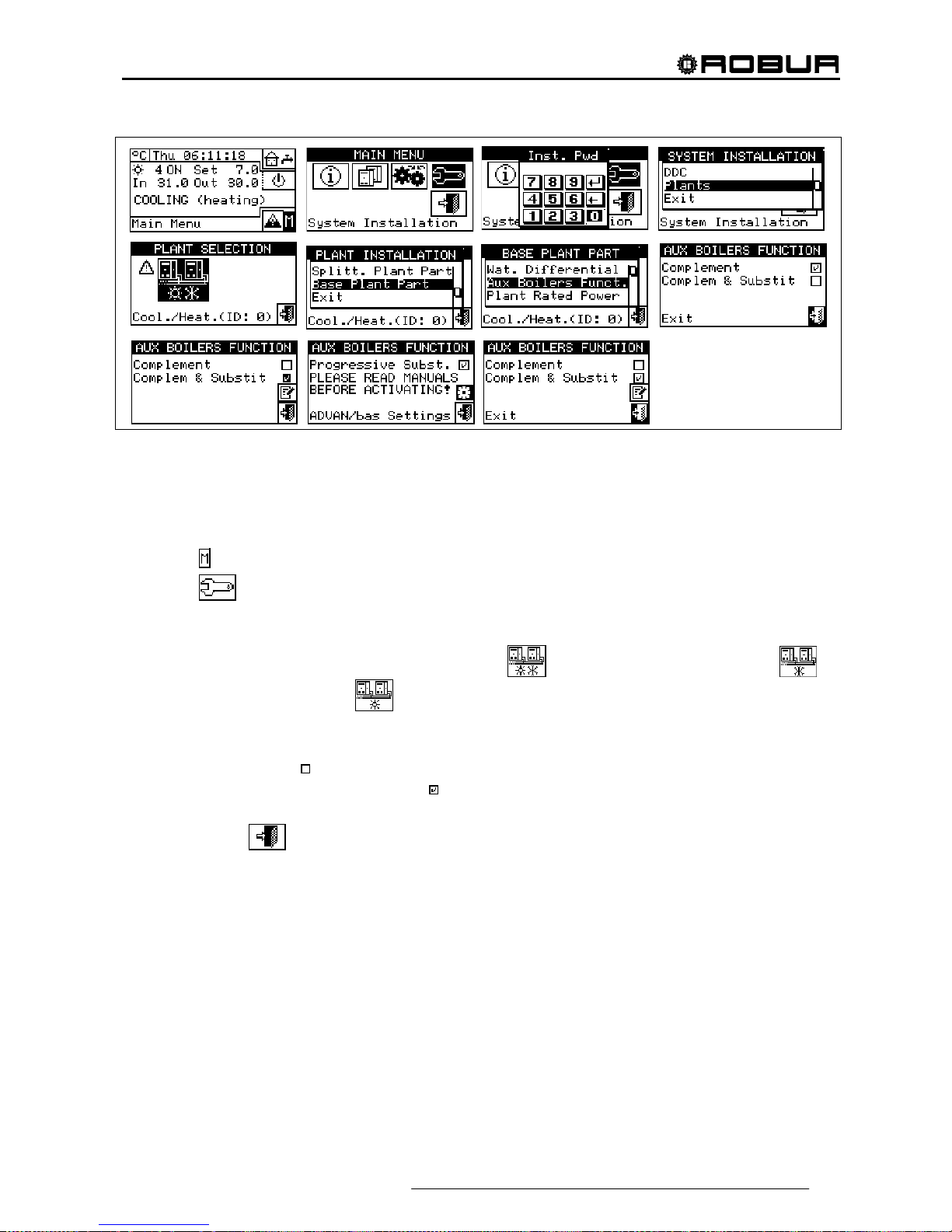
Direct Digital Controller
Direct Digital Controller fw 4.013 – Ed. 01/2013 95
4.4.2.6.3 Rated plant power
The rated plant power can be set only for heating and 2-line cooling/heating plants and only if auxiliary boilers
are operating in “Complement & Substitution” mode (see paragraph 4.2 on page 55).
To set the rated plant power, proceed as follows.
1 - Select
from the initial screen to gain access to the main menu.
2 - Select
to gain access to the System installation.
3 - If required, enter the installer password on the numerical keypad that appears on the display.
4 - Select “Plants” from the drop-down menu.
5 - Select the plant for which the differential is to be set:
for two-line cooling/heating plants, for
hot water production plants, or
for chilled water production plants.
6 - Turn the knob to scroll the cursor downward until highlighting “Base plant part” and press the knob.
7 - Select "Rated Plant Power" from the drop-down menu.
8 - Position the cursor on
next to the option that is to be set: "Default" or "Custom".
9 - Press the knob to activate the option. The
symbol indicates that the option has been enabled .
10 - Select “Custom” to change the power value (expressed in kW).
11 - To exit, select
.

Direct Digital Controller
96 Direct Digital Controller fw 4.013 – Ed. 01/2013
The pre-set option is “Default”, which assigns the sum of the powers of all auxiliary boilers as the rated plant
power. This value is usually correct when the auxiliary boilers run in “Complement and substitution” mode,
as in this case the boilers must provide 100% of the power needed in high thermal load conditions
4.4.2.6.4 Regulation parameters
Setting of the regulation parameters
To set, proceed as described below:
1 - Select
from the initial screen to gain access to the main menu.
2 - Select
to gain access to the System installation.
3 - If required, enter the installer password on the numerical keypad that appears on the display.
4 - Select “Plants” from the drop-down menu.
5 - Select the system for which the parameters are to be set:
for two-line cooling/heating plants,
for hot water production plants, or
for chilled water production plants.
6 - Turn the knob to scroll the cursor downward until highlighting “Base plant part” and press the knob.
7 - Only for two-line hot/cold systems:
8 - The display shows “Carry out semi-automatic configuration?”
9 - If you select “Yes” (normally advised) the display shows “AUTOM. CONFIGURATION enable/disable
integrals”; the DDC automatically calculated for all machine categories the most appropriate values of the
two parameters “enable integral” and “disable integral” according to the values set for the others. The
value is calculated and set when you exit the panel
10 - If you select “No” the display shows “MANUAL configuration of enable/disable integrals.”; the DDC DOES
NOT automatically calculate the two parameters “Enable integral” and “Disable integral”. Use this option if
NOTE
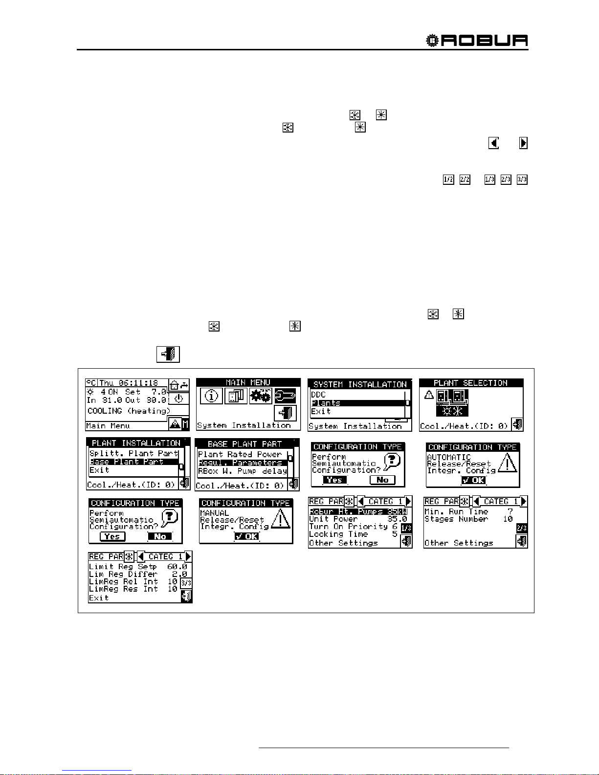
Direct Digital Controller
Direct Digital Controller fw 4.013 – Ed. 01/2013 97
you wish to set the two parameters manually, of to see the values set automatically by the DDC following
previous access to the panel.
11 - Only for 2-line hot/cold systems: select the button with the
or symbol, to select the functioning
mode for which the parameters are to be set:
for HEATING, for COOLING.
12 - Select the category of the machines for which the regulation parameters are to be set using the
and
buttons. Only the categories to which the machines effectively present on the system belong are
proposed.
13 - Choose the page in which the first value to be edited is present, using the buttons
, or , ,
(the number on the left on the button indicates the current page, the one on the right the total number of
pages available).
14 - To edit the set values, position the cursor on the value to edit (for the description of the parameters, refer
to paragraph 4.3.1 “HEATING SERVICE” on page 57 and/or paragraph 4.3.3 “CONDITIONING
OPERATION” on page 64).
15 - Press the knob to allow the change of the selected value.
16 - Turn the knob until the desired value is displayed.
17 - Press the knob to confirm the set value.
18 - If necessary repeat steps 13 - 17 -to complete the parameter settings for the selected category; then,
again if necessary, set the parameters of other categories, executing step 12 - and steps 13 - 17 - again.
19 - Only for 2-line hot/cold systems: if necessary select the button with the symbol
or again to select
another operating mode:
for HEATING, for COOLING and repeat steps 12 -18 to set the
parameters for the machine categories in the newly selected operating mode.
20 - To exit, select
.

Direct Digital Controller
98 Direct Digital Controller fw 4.013 – Ed. 01/2013
4.4.2.6.5 RoburBox water pump delay
This parameter is used to set the switch-off delay on the common primary water pump and/or the secondary
plant water pump, if at least one of these is configured and managed by RB200; if neither of the two water
pumps is configured, access to the parameter settings panel is denied.
1 - To set the delay, proceed as described below:
2 - Select
from the initial screen to gain access to the main menu.
3 - Select
to gain access to the System installation.
4 - If required, enter the installer password on the numerical keypad that appears on the display.
5 - Select “Plants” from the drop-down menu.
6 - Select the system for which the parameters are to be set:
for two-line cooling/heating plants,
for hot water production plants, or for chilled water production plants.
7 - Turn the knob to scroll the cursor downward until highlighting “Base plant part” and press the knob.
8 - Select “RBox W Pump Delay” from the drop-down menu.
9 - To modify the values set, position the cursor on the value to be modified.
10 - Press the knob to allow the change of the selected value.
11 - Turn the knob until the desired value is displayed.
12 - Press the knob to confirm the set value.
Take care not to confuse this parameter with the "Water pump delay" parameters which may be present in
the regulation parameter settings panel of various categories of units (see Third party boiler water pump delay
on page 63 and Third party chiller water pump delay on page 65): these parameters are in fact used to set the
switch-off delay of water pumps dedicated to third party units, if present and controlled by the Robur system.
NOTE
 Loading...