

Page 1
Design manual
AD evaporative coolers
Page 2

Revision: A
Code: D-MNL053EN
This Design manual has been drawn up and printed by Robur S.p.A.; whole or partial reproduction of this Design manual is prohibited.
The original is led at Robur S.p.A.
Any use of this Design manual other than for personal consultation must be previously authorised by Robur S.p.A.
The rights of those who have legitimately led the registered trademarks contained within this publication are not aected.
With the aim of continuously improving the quality of its products, Robur S.p.A. reserves the right to modify the data and contents of this
Design manual without prior notice.
Page 3

Design manual AD evaporative coolers
INDEX OF CONTENTS
1 Premise .........................................................................................
2 Cooling and ventilation .................................................
2.1 Microclimate within the room ....................................
2.2 Safety, health and productivity ..................................
3 The technical solution .....................................................
3.1 The result and the advantages ...................................
3.2 System operation ............................................................
3.3 Performances of the system ........................................
4 Air psychrometric chart .................................................
5 The evaporative cooler ..................................................
5.1 Evaporative cooler operation .....................................
5.2 Description of the automatic cleaning system
...............................................................................................
5.3 Routine maintenance ....................................................
6 Design of a cooling and ventilation system
..............................................................................................................
6.1 Outdoor summer design conditions .......................
6.2 Air diusers installation height in the building
...............................................................................................
6.3 Number of air renewals required depending on
the type of activity in the building .........................
6.4 Exhaust air evacuation ................................................
p.4
p.4
p.4
p.4
p.4
p.5
p.5
p.5
p.6
p.8
p.8
p.8
p.9
p.9
p.9
p.9
p.10
p.10
7 Choice of models and number of coolers
to be installed .......................................................................
7.1 Available range ..............................................................
7.2 Sizing examples .............................................................
7.3 Evaporative cooler installation .................................
8 Electrical and water supply network ...............
8.1 Water supply network .................................................
8.2 Electrical supply network ...........................................
9 Evaluation of the eective eciency of
the coolers................................................................................
9.1 Water consumption is synonymous with
eciency ..........................................................................
9.2 Evaporative packs crossing speed ..........................
10 Control and regulation solutions .......................
10.1 ECO basic remote control ..........................................
10.2 EVO advanced remote control .................................
10.3 Centralized control .......................................................
11 Diusion plenums ............................................................
11.1 Dimensions .....................................................................
12 Technical data and dimensions ............................
12.1 Technical characteristics .............................................
12.2 Dimensions .....................................................................
12.3 Installation examples ...................................................
p.10
p.10
p.10
p.10
p.11
p.11
p.12
p.12
p.12
p.12
p.13
p.13
p.13
p.14
p.16
p.16
p.17
p.17
p.17
p.18
Cod.: D-MNL053EN 19 MED SDC 008
Rev.: A
AD evaporative coolers
07/06/2019
3
Page 4
AD evaporative coolers
97%
X
Y
700%
X
1 PREMISE
The purpose of this Design manual is to provide a rst set of information on the operation, design and characteristics of cooling systems with evaporative coolers Robur AD.
Robur also provides a spreadsheet for a preliminary design of
cooling systems with Robur AD units.
The Robur technical service is always at your disposal for any further technical information on the application and use of these
appliances.
2 COOLING AND VENTILATION
The evaporative cooling system is the most modern technology
for cooling and ventilation of large rooms:
▶
production and crafts premises
▶
commercial premises and warehouses
▶
sports premises in general
This system allows you to equip even large rooms with summer
ventilation and cooling system to improve the comfort of people, increase their well-being and productivity, without committing large capital for plant expenses, without incurring high
operating costs for energy consumption, without producing environmental impact and without the risk of power blackouts for
over-demand.
2.1 MICROCLIMATE WITHIN THE ROOM
Inside a large room, such as an industrial building, a microclimate is established during the hot seasons that is dicult for the
people who work there to endure.
The heat input of process plants, electrical power plants and
building structures which, when hit by the sun, transmit a high
level of thermal energy to the internal air, often cause an unbearable thermal condition in the environment.
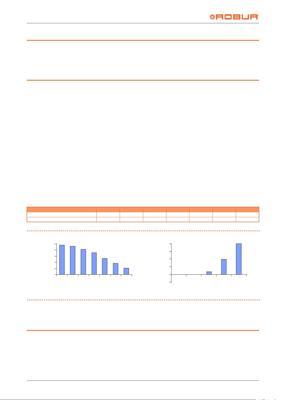
Table2.1 NASA Report CR-1205-1
Ambient temperature 23 °C 26 °C 29 °C 32 °C 35 °C 37 °C 40 °C
Loss in productivity 3% 8% 18% 29% 45% 62% 79%
Loss in accuracy - 5% 40% 300% 700% - -
Furthermore, during the night, when the room is closed, the
heat stagnates inside the room, creating already in the morning
conditions of poor comfort.
In addition to all this, there is usually a lack of proper air renewal
necessary for the disposal of exhaust air, sometimes harmful to
the health of workers.
2.2 SAFETY, HEALTH AND PRODUCTIVITY
The conditions of discomfort caused by high temperatures within an industrial environment cause operators to experience the
so-called "heat stress", which begins to be eective above 27 °C
causing:
▶
Lowering of morale, delays and absenteeism
▶
reduced attention to safety, increase in the percentage of
injuries
▶
potential health issues
▶
reduced productivity, reduced production quality
Research has shown that this working condition adversely affects productivity and production quality, as shown for example
by a NASA report:
Figure2.1 NASA Report CR-1205-1
100%
80%
60%
40%
20%
0%
X = internal temperature Y = productivity Z = loss of accuracy
NASA Report CR-1205-1 shows for example that when temperatures inside the building rise over 29 °C, productivity drops by
92%
82%
71%
55%
38%
21%
23°C 26°C 29°C 32°C 35°C 37°C 40°C
700%
500%
Z
300%
100%
18% and quality decreases by 40% due to increase in working
errors.
0%
0%
23°C 26°C 29°C 32°C 35°C
3 THE TECHNICAL SOLUTION
To improve the summer microclimate inside a large room and
reach an adequate level of well-being, the environment must be
ventilated with cooled air and many new air renewals must be
granted to neutralize all heat supply.
The continuous renewal of the ambient air prevents the accumulation of heat inside the building and prevents the excessive
increase of the internal temperature.
The air renewal also allows to improve the level of environmental
hygiene, to dispose of any smells or hazardous gases and to improve productivity and safety of people.
A ventilation and cooling system with AD units consists of evaporative coolers that cool the air with a natural principle and not
through a refrigeration cycle.
The evaporative cooler is an appliance that cools the air by reducing the sensible heat contained in it.
The reduction of the sensible heat is due to the evaporation
5%
300%
40%
Rev.: A
AD evaporative coolers
07/06/2019
4
Cod.: D-MNL053EN 19 MED SDC 008
Page 5
Design manual AD evaporative coolers
process of the water that comes into contact with the treated air:
the air taken from the outside passes through cellulose panels
of particular structure wet with water, gives up part of its heat
during the process of evaporation of the water and lowers its
temperature.
A fan, incorporated in the cooler, provides for the supply of the
cooled air into the room.
The operating principle is very simple: if the system expels all the
introduced air, the system produces maximum eciency, grants
all the planned air renewals and cools the environment under
the design conditions.
It is also possible to have a slightly lower extract air ow than the
supplied one (but not less than 80%), which allows the room to
be kept slightly overpressurised compared to the outside, preventing the outside hot air from re-entering the room through
3.1 THE RESULT AND THE ADVANTAGES
The absence of refrigerating units reduces by 70% the system
cost and by 80% the electrical energy consumption, which is
reduced to that necessary for the fan operation, signicantly reduces the size of the systems and simplies installation, operation and maintenance.
In general, the advantages that can be obtained with this solution are:
▶
treatment of large volumes of air to achieve many hourly air
renewals
▶
air cooling
▶
possibility of ventilation only in the less hot seasons
▶
possibility of partial or dierentiated management for dier-
the natural openings.
The ideal condition is to place the air diusers away from the
openings (windows, doors, etc.) and distribute them evenly inside the room. By opening a window away from the diusers, the
air passes through the room cooling it before being extracted.
By calculating the correct dimensions of the evacuation openings the maximum eciency of the system is reached. The system must be able to extract the large volume of air supplied so
as not to reduce the eectiveness of the system.
If the available openings are not sucient, it is necessary to add
forced air extraction systems (extraction towers).
Failure to comply with these conditions precludes the planned
air renewal, reduces the cooling eect and increases the relative
humidity inside the room.
ent areas of the room
▶
low cooling system costs, low running costs, low maintenance costs
▶
no use of environmentally harmful refrigerant gases (such as
CFC/HFC and greenhouse gases)
▶
improvement of hygiene in the room
▶
increase of the productivity, quality and safety of internal
sta
3.3 PERFORMANCES OF THE SYSTEM
The evaporative cooling system exploits the air adiabatic saturation process: the unsaturated humid air is saturated by bringing
it into very close contact with water, so that heat exchanges take
place only between air and water without other exchanges with
the outside.
All the heat that the water receives from the air serves to evap-
3.2 SYSTEM OPERATION
orate part of it, so the enthalpy of the residual water remains
unchanged as well as its temperature. It follows that even the
enthalpy of air does not change.
3.2.1 Ventilation and cleaning of the room
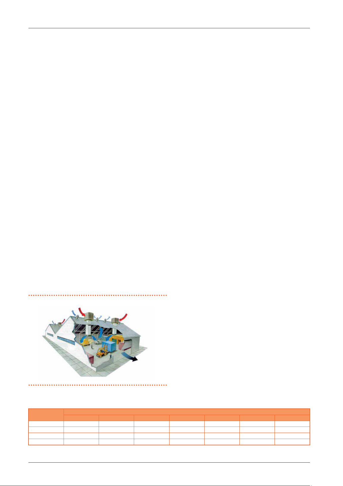
The evaporative cooling system is a system that works dynamically and works on the basis of a natural principle: it introduces
large quantities of cooled external air into the room and extracts
the exhausted hot air through doors, windows and other evacuation openings that are left open.
The air temperature is therefore reduced, up to the maximum
temperature of the water, while its humidity increases.
Since the enthalpy of the air is the sum of elements as a function
of temperature (sensible heat) and of an element as a function of
humidity (latent heat), if its temperature decreases and the humidity increases, it means that the sensible heat has decreased
and the latent heat has increased (unchanged enthalpy). Of
Figure3.1 Air ow in the room
course, the system increases its air cooling capacity as the relative humidity of the outdoor air decreases: the drier the outside
air is, the higher its possibility of saturation, the higher the reduction of the sensible heat contained in it, therefore the greater
the decrease of the obtainable air temperature.
The cooling capacity of the air is also due to the technical characteristics of the exchange device (the evaporator) or to its saturation eciency: in fact, the longer the time and surface contact
between air and water, the more the water evaporates and the
air temperature (sensible heat) decreases.
The AD evaporative cooler is equipped with a high saturation
eciency evaporating unit which produces a good level of cooling even at relative air humidity values of around 70%.
The temperature of the air supplied to the room is a function
of the dierent conditions of the outside air, according to Table
3.1
p.5
.
Table3.1 Temperature of the air supplied to the room
External temper-
ature
25 °C 13,7 15,4 17,0 18,6 20,0 21,3 22,6
30 °C 17,0 19,1 21,0 22,8 24,4 26,0 27,4
35 °C 20,4 22,9 25,1 27,1 29,0 30,6 32,1
40 °C 23,0 26,0 29,0 31,5 33,5 36,5 38,0
20% 30% 40% 50% 60% 70% 80%
Relative humidity of the inlet air
Cod.: D-MNL053EN 19 MED SDC 008
Rev.: A
AD evaporative coolers
07/06/2019
5
Page 6

AD evaporative coolers
Tr Tbu Ta
12
4 AIR PSYCHROMETRIC CHART
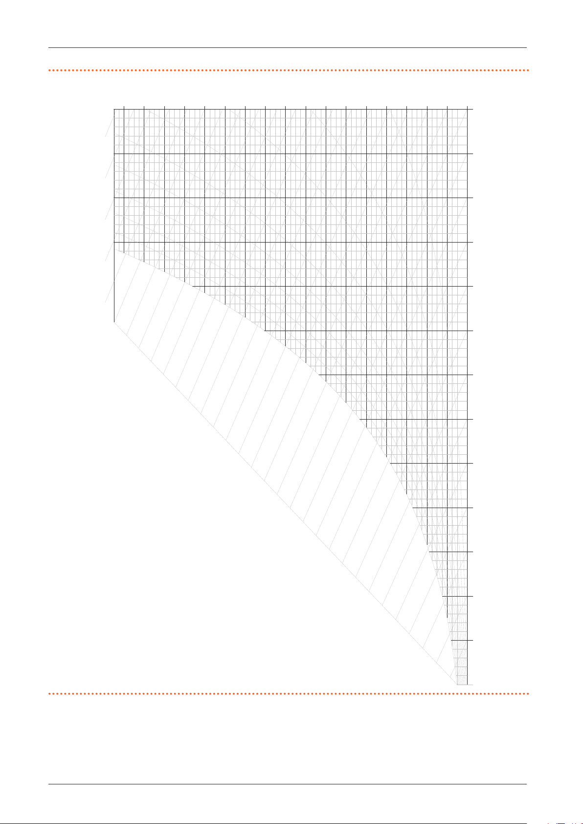
The performance of an evaporative cooling system varies according to the physical conditions of the treated air, they depend
Figure4.1 Air psychrometric chart - legend
7
8
9
on the saturation eciency of the evaporative pack and can be
obtained using air psychrometric chart.
1
2
3
11
6
A
4
5
1 Dry temperature
2 Deviation of the enthalpy
3 Relative humidity
4 Specic humidity
5 Specic volume
6 Wet temperature
7 Enthalpy
8 Saturation curve
9 Pole
10 Dry bulb temperature
10
11 Specic humidity
12 Thermal factor
Ta Ambient temperature
Tr Dew temperature
Tbu Wet bulb temperature
6
Cod.: D-MNL053EN 19 MED SDC 008
Rev.: A
AD evaporative coolers
07/06/2019
Page 7
Tbs -10 -5 0 5 10 15 20 25 30 35 40 45 50
125 130 135 140 145
US [g/kg]
Design manual AD evaporative coolers
Figure4.2 Air psychrometric chart
34
32
30
120
115
110
105
100
28
26
100
95
90
85
80
22
20
18
16
14
12
10
8
6
4
2
24
90
75
70
70
80
65
60
55
50
45
50
60
40
35
30
25
30
40
20
15
10
Entalpia [kJ/kg]
5
20
0
-5
0
10
-10
It should therefore be specied that the evaporative cooling system provides a dierent degree of comfort to the environment
as the physical conditions of the outdoor air change, and cannot
guarantee constant and predened temperature and humidity
conditions.
Cod.: D-MNL053EN 19 MED SDC 008
Rev.: A
AD evaporative coolers
07/06/2019
7
Page 8
AD evaporative coolers
5 THE EVAPORATIVE COOLER
The AD evaporative cooler is an appliance powered by electricity
and mains water, which is installed on the roof or on the external wall or in correspondence with a window of the room to be
ventilated and cooled.
Ducts and air diusers are connected to it to distribute the
cooled air in the room.
The coolers are equipped with an external load-bearing structure in ABS that guarantees protection from the weathering
and a particular lightness, a very important aspect in relation to
the limited load-bearing capacity of the roofs and walls of the
buildings.
The coolers are equipped with:
▶
low consumption electric fans
▶
water loading system with solenoid valve
▶
water distribution system with electric pump
▶
evaporation panels with high saturation eciency
▶
automatic water drainage system
▶
automatic periodic cleaning for the whole hydraulic circuit
and the evaporating panels
▶
electronic command and operation panel
5.1 EVAPORATIVE COOLER OPERATION
Each cooler is equipped with a remote electronic control and
operation panel for adjusting the air speed and for choosing the
various functions:
▶
ventilation only
▶
ventilation and cooling
The panel contains the logic unit for setting the functions necessary for the operation of the cooler, including the periodic
washing of the evaporating panels and the washing and the
drainage at the end of the cycle; these functions are essential for
maintaining high performance over time and for preventing the
proliferation of bacterial forms.
Depending on the remote control chosen and used, it is also
possible to adjust the microclimate in each zone according to
the real needs of the time and season or according to the personal perception of the operator directly concerned, thanks to
the weekly and daily timer, to the maximum percentage of relative humidity required and to the fan speed.
▶
When the machine is started, the water discharge valve (nor-
mally open) closes, the water loading valve opens and allows
water to enter the collection tank. A level switch limits the
water load up to the amount required for the cooling cycle.
▶
An electric recirculation pump lifts the water up to the dis-
tributor circuit which wets the evaporating panels.
▶
The electric fan starts and sucks in the outside air through
the wet evaporating panels and feeds it into the room
through the delivery outlet.
▶
The water that evaporates during the cycle is replenished on
command of the level switch of the collection tank.
▶
By acting on the control panel, it is possible to interrupt the
cooling function and operate the appliance in ventilation
mode only, granting in any case the required air renewal.
▶
By acting on the fan speed regulator it is possible to custom-
ize the ow and the quantity of air introduced into the room.
There is an automatic washing cycle every 3 hours (standard):
the appliance suspends its evaporation cycle for a few minutes,
the water contained in the tank is discharged and replaced with
clean water that is circulated through the evaporative packs in
order to wash out the residues of mineral salts and any other
deposits.
The repetitiveness of these washes prevents the crystallization
of minerals and other elements on the evaporative packs and
throughout the circuit, guarantees a long life and maintains a
high saturation eciency.
Each time the unit is switched o, a nal wash cycle is performed.
At the end, the cooler discharges all the water contained in it
to prevent water stagnation from causing the development of
bacterial forms and the formation of limescale deposits.
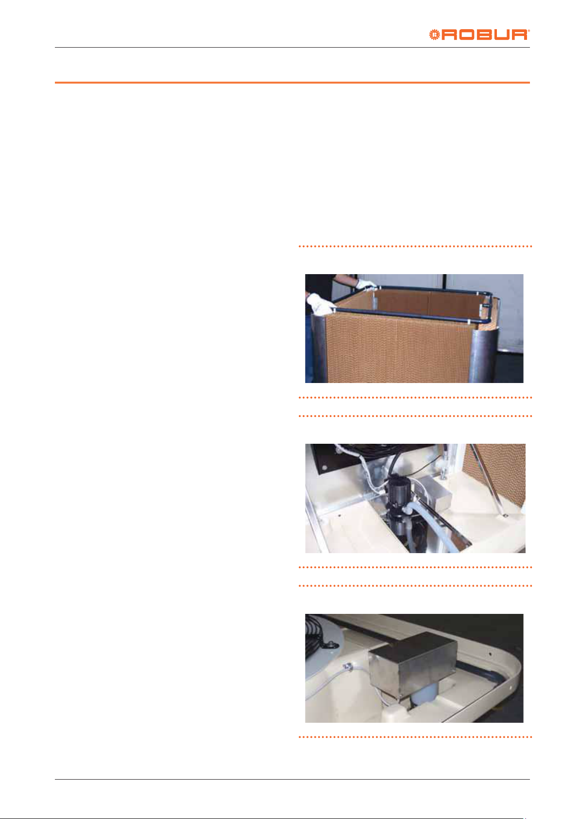
Figure5.1 Cellulose evaporating panels
Figure5.2 Recirculation pump and water distribution system
Figure5.3 Automatic washing and emptying device
5.2 DESCRIPTION OF THE AUTOMATIC
CLEANING SYSTEM
The cooler is equipped with an automatic washing system for
the evaporative pack and the water collection tank which, at
programmable intervals, is automatically activated to maintain
a high level of cleanliness and saturation eciency.
8
Cod.: D-MNL053EN 19 MED SDC 008
Rev.: A
AD evaporative coolers
07/06/2019
Page 9
Design manual AD evaporative coolers
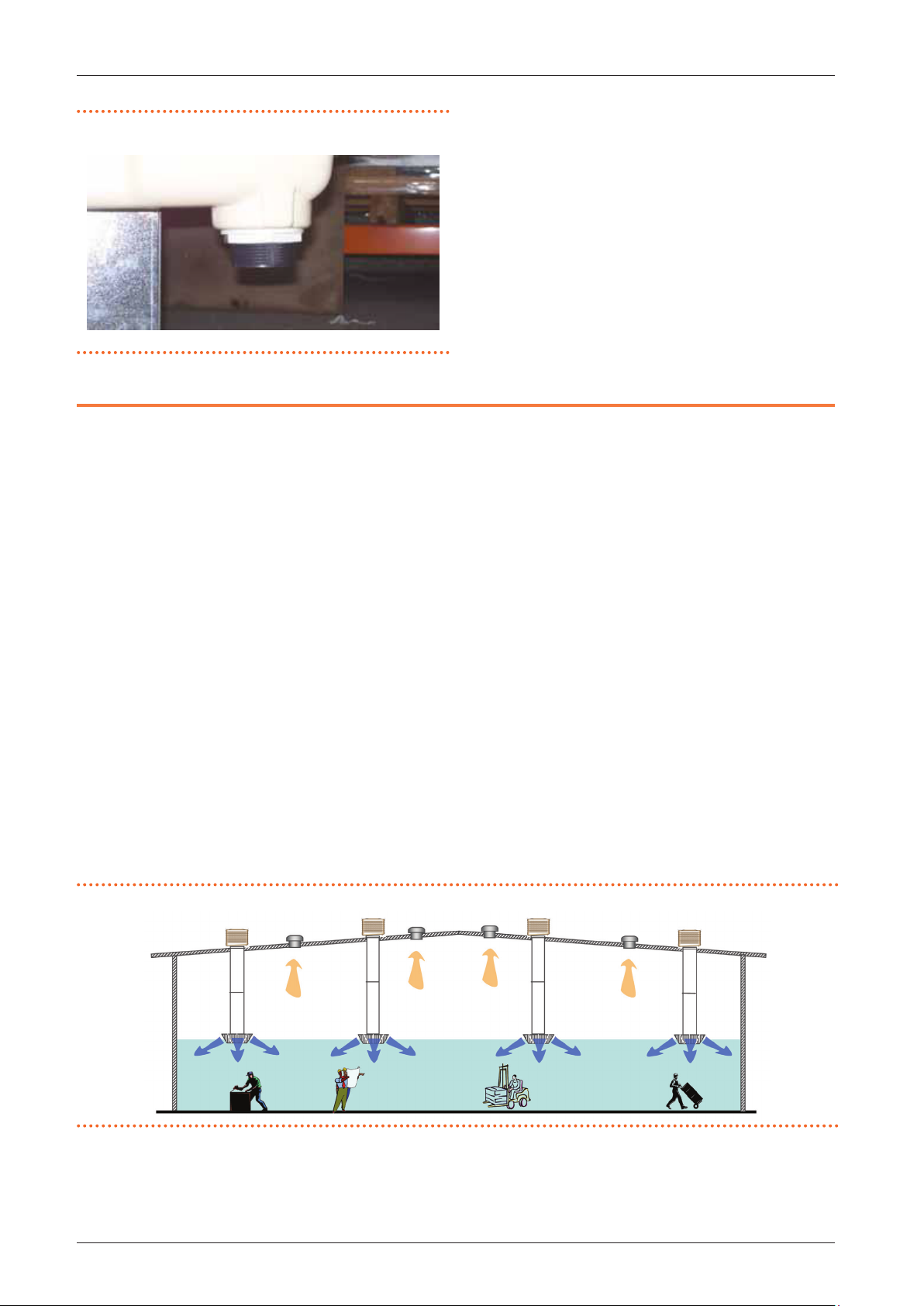
Figure5.4 Water drain device
5.3 ROUTINE MAINTENANCE
Routine maintenance of the evaporative cooler is limited to endof-season cleaning, which includes washing the water distribution circuit, the evaporative packs, the recirculation pump and
the water collection tank.
In the winter season it is necessary to drain all the water contained in the supply system to avoid damage caused by freezing.
The cooler can be covered with a winter cover (optional
OCPR003) to protect it from weathering and to prevent the intrusion of cold air into the room.
Every three to four years we recommend replacing the evaporating panels.
6 DESIGN OF A COOLING AND VENTILATION SYSTEM
The purpose of the system is to cool and ventilate a large room
during the hot seasons, lowering the temperature of the indoor
air compared to the outdoor air and making the necessary air
renewal to improve the microclimate inside the room.
The lowering of the internal temperature will help to neutralize
the heat contributions coming from the structures of the building, from the sun's rays, from the process plants inside.
Air renewal will help to dispose of the exhausted air and any
fumes, vapours, smells or other aeriforms, often harmful to the
health of workers.
The cooling eciency is not only related to the eciency of the
appliance, but also to the design of the ductwork and the installation. Insulated ceilings will decrease the internal temperature
signicantly compared to non-insulated ceilings. The same concept is applicable for air ducting.
In order to size the plant we must take into account four fundamental elements:
1. the outdoor summer design conditions
2. the installation height of the air diusers in the room
3. the number of air renewals required according to the type of
activity carried out in the room
4. evacuation of exhaust air
6.1 OUTDOOR SUMMER DESIGN
CONDITIONS
As already seen, the AD evaporative cooler is a system that works
dynamically and operates on the basis of a natural principle: it
introduces large quantities of external and cooled air into the
room and expels the exhausted hot air through doors, windows
and other exhaust openings.
The cooling of the air taken from the outside and introduced
into the room is a function of the outdoor conditions (Table
3.1
p.5
).
6.2 AIR DIFFUSERS INSTALLATION HEIGHT
IN THE BUILDING
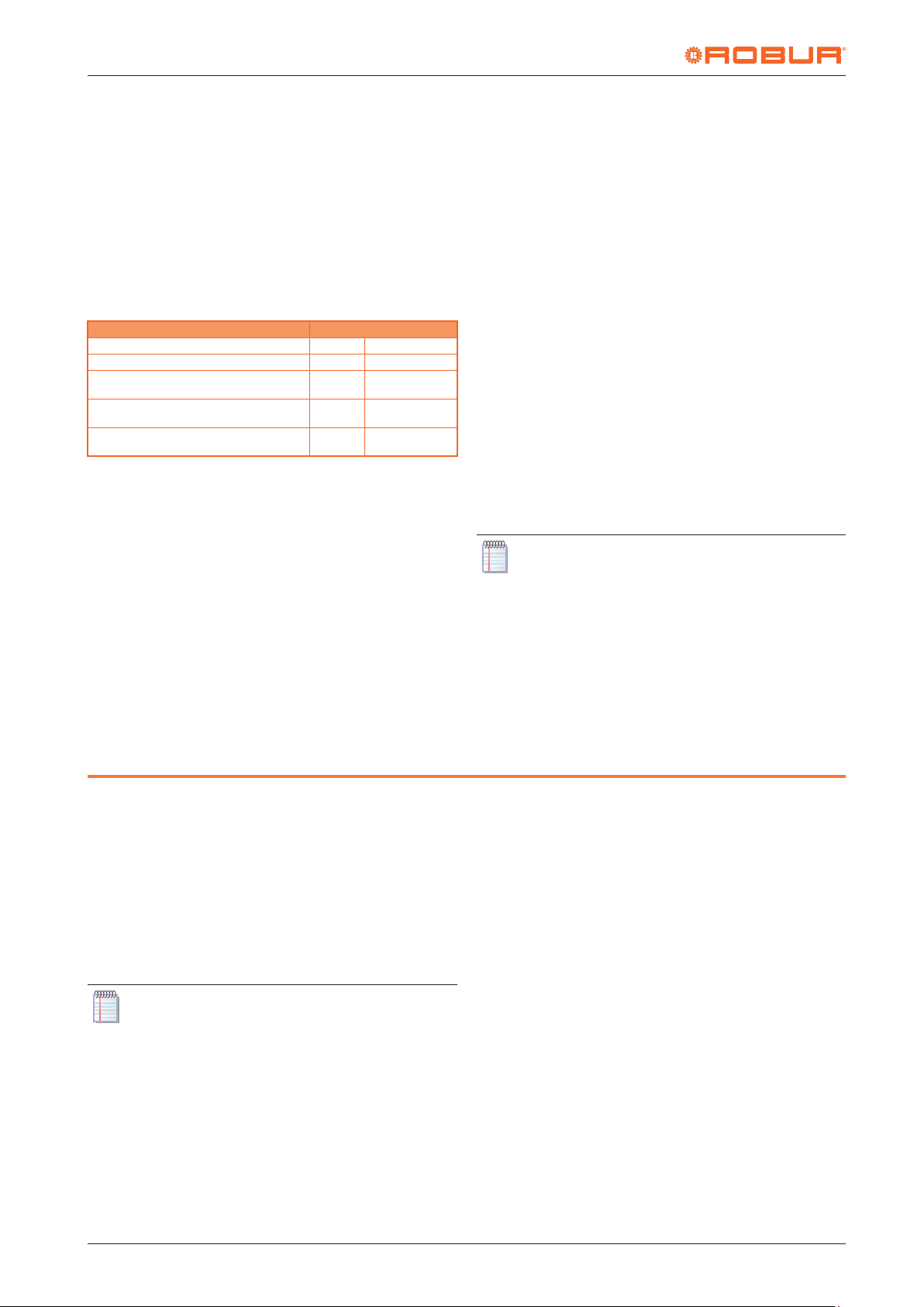
The air coming from the coolers tends to descend towards the
oor and to push up the warmest one. The area of inuence that
interests us is the one where people work, so the volume to be
cooled is that between the oor and the height of diusion of
the cooled air.
To allow normal operation, the air diusers must be installed no
less than 4 metres above the ground and, in order not to unnecessarily cool the upper part of the room, it is recommended not
to exceed 6 metres in height.
It should be noted that the higher the installation height of the
diusers, the lower the cooling eect near the oor.
The volume to be treated is therefore equal to the surface area
of the area concerned multiplied by the height from the ground
of the diusers.
Figure6.1 Positioning of diusers and extractors
Cod.: D-MNL053EN 19 MED SDC 008
Rev.: A
AD evaporative coolers
07/06/2019
9
Page 10
AD evaporative coolers
6.3 NUMBER OF AIR RENEWALS REQUIRED
DEPENDING ON THE TYPE OF ACTIVITY
IN THE BUILDING
Once the volume to be cooled has been identied, it is necessary
to multiply it by the number of air renewals per hour required according to the type of activity. The quantity of air to be supplied
to the room is thus obtained to grant the required air renewal
and the cooling of the environment.
Table 6.1
p.10
indicates the minimum suggested air renewal
for dierent activities.
Table6.1 Air renewal according to the activity
Activity Air renewal
Oces and shops v/h 8 ÷ 10
Light processing (warehouses, storage areas) v/h 10 ÷ 15
Medium processing (production and assembly
areas)
Heavy processing (presence of ovens, equip-
ments with moderate heat development)
Extreme conditions (foundries, furnaces with
high heat generation)
v/h = volumes/hour.
v/h 15 ÷ 20
v/h 20 ÷ 30
v/h 30 ÷ 40
6.4 EXHAUST AIR EVACUATION
Once the quantity of air to be supplied to the room has been
identied, the size of the openings required for exhaust air extraction must be calculated.
The system involves the introduction of cooled air into the room
and the extraction of at least 80% of it through natural openings
or forced extraction systems.
The extraction of at least 80% of the air introduced is essential
to grant the planned renewals, to grant the cooling eect and to
avoid an increase in the percentage of relative humidity in the
room.
The extraction of a quantity of air slightly lower than the one introduced (but not less than 80%) allows to keep the cooled room
in a slight overpressure compared to the outside, preventing the
outside hot air from re-entering the room through the natural
openings.
The air produced by the coolers contains a percentage of relative
humidity higher than that of the external air and that of the air
in the building: this is precisely the characteristic that produces
the cooling eect. For this to be eective, however, it must pass
through the room and then leave. In this way, the percentage of
relative humidity in the room will not increase and the cooling
eect will be granted.
To extract the exhaust air, natural openings of about 1 m2 per
1000 m3 of air are required.
If it is necessary to evacuate 10000 m3 of air it will take about 10
m2 of natural openings.
It is important that the openings (windows, doors, gates, skylights, ...) are not concentrated in a single position or only on one
side of the room, but that they are distributed throughout the
building to allow ventilation and cooling of the whole room and
not only of a part of it.
The best result is obtained when there are also openings on the
roof, such as skylights or natural extractors: through these openings it is possible to evacuate the mass of hot air that is underneath the roof and usually stays there for a long time.
If the natural openings are larger than the amount required to evacuate the exhausted air, or if the extracted
air ow rate is greater than 80% of the supplied air, there
is a risk of attracting more hot air from outside and reducing the cooling eect.
If there are already forced extraction systems in operation in the
room, their capacity must be taken into account and subtracted
from the calculation of the necessary openings.
It is necessary to ensure that there is a correct balance between
the amount of air entering and leaving the room.
7 CHOICE OF MODELS AND NUMBER OF COOLERS TO BE INSTALLED
The choice of models and the number of AD coolers to be installed depends on the customer's needs, on the dierent possibilities of positioning the coolers and the air ducts, considering
that the installation quota of the air diusers should not exceed
6 m from the ground.
The ideal choice is to install the coolers on the roof of the building and enter with the ducts through the skylights.
The quantity of coolers to be installed depends on the calculated intake air ow rate:
Number of coolers = total air ow (m³/h) / air ow of the selected
coolers (m³/h).
It is important to distribute the air in the room as evenly
as possible.
7.1 AVAILABLE RANGE
The AD evaporative coolers are available in two models, which
dier in the maximum air ow that can be delivered:
▶
AD14 with air ow up to 13000 m³/h
▶
AD20 with air ow up to 20000 m³/h
Three dierent versions are available for each model, two of
which are equipped with an independent basic (ECO) or advanced (EVO) remote control for each unit, and the third (SC) is
suitable for the centralised management of a system composed
of a maximum of 30 units, to be associated with a centralised
control system, supplied by Robur.
The three versions can be summarized as follows:
▶
AD14/AD20 ECO: equipped with the basic ECO remote control (Paragraph 10.1
▶
AD14/AD20 EVO: equipped with the advanced EVO remote
control (Paragraph 10.2
▶
AD14/AD20 SC: without individual remote control, but designed for a centralised control (Paragraph 10.3
p.13
).
p.13
).
p.14
7.2 SIZING EXAMPLES
Surface area of building to be cooled: 2000 m²
Building height: 8 m
Height of the cooled air diusers: 5 m
Type of activity carried out inside: medium processing
Expected air renewal: 15 v/h
Net volume to be cooled: 2000 x 5 = 10000 m³
Total required air ow: 10000 x 15 = 150000 m³
Single cooler air ow rate: 20000 m³/h (model AD20)
Number of coolers to be provided: 150000/20000 = 8 AD20
7.3 EVAPORATIVE COOLER INSTALLATION
The installation works are very simple and consist of clamping
the machines in the chosen position, connecting the ducts and
).
10
Cod.: D-MNL053EN 19 MED SDC 008
Rev.: A
AD evaporative coolers
07/06/2019
Page 11
Design manual AD evaporative coolers
1
2
4
1
2
3
4
5
air diusers, the construction of the water supply and drainage
network and the power supply network and the connection of
the electronic control.
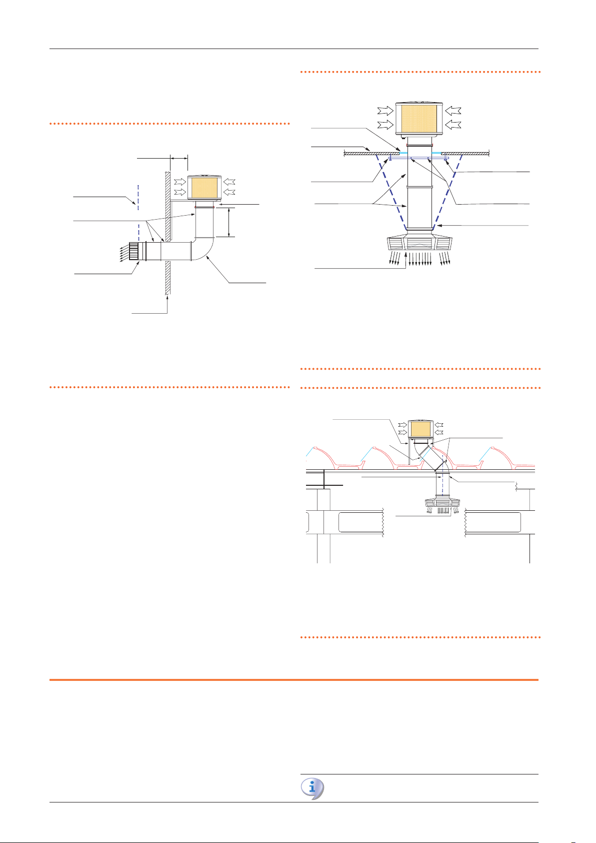
The following Figures show installation examples.
Figure7.1 Installation example
≥ 0,4 m
6
≥ 1 m
3
5
1 Galvanized or stainless steel chains for xing the channels to the ceiling
2 Duct with anges and neoprene gaskets
3 2-way diuser with adjustable ns
4 Wall
5 90° curve with anges and neoprene gaskets
6 Support frame
Figure7.2 Installation example
6
7
8
1 Skylight
2 Coverage
3 Stainless steel brackets
4 Duct with anges and neoprene gaskets
5 6-way diuser with adjustable ns
6 Dowels to x the brackets to the ceiling
7 Screws to x the duct to the brackets
8 Galvanized or stainless steel chains for xing the channels to the ceiling
Figure7.3 Installation example
1
2
3
1 Support frame
2 Duct with anges and neoprene gaskets
3 Galvanized or stainless steel chains for xing the channels to the ceiling
4 6-way diuser with adjustable ns
5 45° curve with anges and neoprene gaskets
6 Duct with anges and neoprene gaskets
8 ELECTRICAL AND WATER SUPPLY NETWORK
5
6
4
8.1 WATER SUPPLY NETWORK
The water necessary for the cooler operation can be drawn directly from the local water mains.
No kind of softening treatment is necessary as the cooler provides for periodic programmed cleaning of the internal circuits
to avoid the formation of limescale deposits and the crystallization of the mineral salts contained in the water.
Cod.: D-MNL053EN 19 MED SDC 008
Rev.: A
AD evaporative coolers
If you feel you have particularly hard water, you can program
more frequent washes.
It is advisable to install the water supply network inside the
building to protect it from freezing in the winter season and
from the sun's rays during the summer; otherwise, it is recommended to install a suitably insulated pipe.
The water supply system must grant a minimum ow
07/06/2019
11
Page 12
AD evaporative coolers
1
3
4
rate of 7 l/min for each unit at a pressure of 1,5÷3 bar
(maximum allowed pressure: 6 bar).
The distribution network must be equipped with a suitable lter
to prevent the passage of solid elements, such as sand and dirt.
The AD evaporative cooler is equipped with a water supply connection located in the lower part of the external structure (detail
A Figure 12.1
p.17
and 12.2
p.18
).
It is recommended to install an isolation valve at the inlet of the
unit and make the connection to the water supply with a exible
stainless steel pipe.
It is recommended to provide for the possibility of
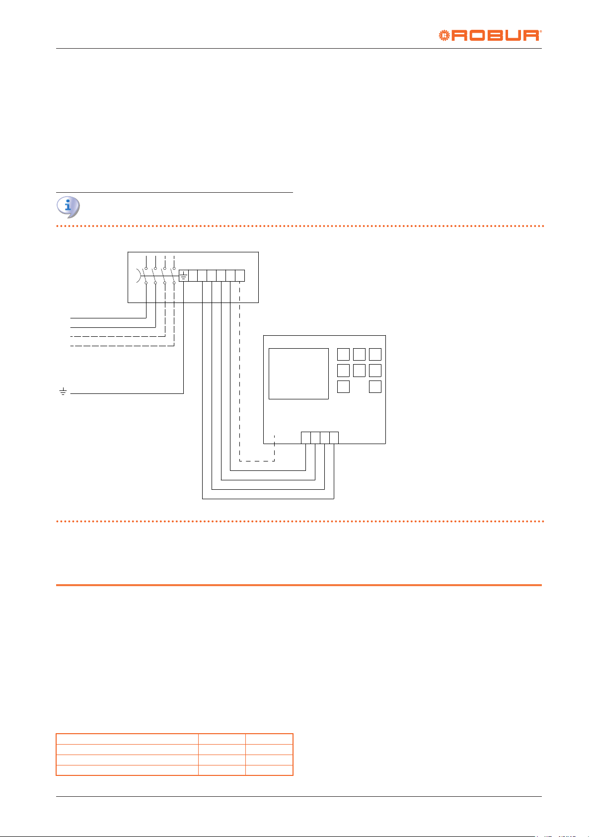
Figure8.1 Electrical wiring diagram
V+
V-
L1 L2
M/S
X
A1
2
emptying the entire water supply system before the start
of the winter season to avoid damage due to freezing.
The evaporative cooler is equipped with a sleeve located on the
bottom of the external structure for the connection of the water
discharge pipe of the periodic washes.
Refer to Table 12.1
p.17
for water connection dimensions and
water consumption.
8.2 ELECTRICAL SUPPLY NETWORK
The supply voltage of AD appliances is 230 V - 50 Hz.
The electrical system must be constructed according to the regulations in force in the country where the machine is installed.
1 Onboard electrical panel
2 Power supply 230 V - 50 Hz
3 Remote control
4 20 AWG 5x0,5 mm2 shielded cable
5 Do not connect
A1 Main switch onboard the appliance
BRO Brown
WHI White
GRE Green
YEL Yellow
GRY Grey
YEL
WHI
GRE
BRO
MAX 25 m
The cooler must be connected to the selected remote control
(Paragraph 10
9 EVALUATION OF THE EFFECTIVE EFFICIENCY OF THE COOLERS
p.13
), which is normally installed in the cooled
9.1 WATER CONSUMPTION IS SYNONYMOUS
WITH EFFICIENCY
These appliances base their operating principle on the ability to
evaporate water using the heat contained in the air treated by
the cooler. In other words, the higher the water consumption,
the greater the cooling eect.
Using the parameters of Table 9.1
for every liter of water evaporated from 1000 m³ of air, there will
be a reduction in air temperature of about 2 ° C.
Table9.1 Air and water parameters
Latent water evaporation heat J/kg 2260000
Water density kg/m³ 997
Air specic heat J/kg @40 °C 1005,5
Air density kg/m³ 1,14
p.12
GRY
5
we can estimate that
A3
V-
V+
L2 L1
room.
In the case of an AD14 cooler we have:
▶
air ow: 13000 m³/h
▶
water consumption: 43 l/h
▶
temperature gradient of the outlet air: 6,5 °C
In general, if you want to make a comparison with other types
of coolers, the lower the declared water consumption, the lower
the cooling eect that can be obtained.
9.2 EVAPORATIVE PACKS CROSSING SPEED
The crossing speed of the evaporative packs of the treated air
also contributes to the eciency of the appliance as a whole.
In fact, the producers of the exchange packs usually provide a
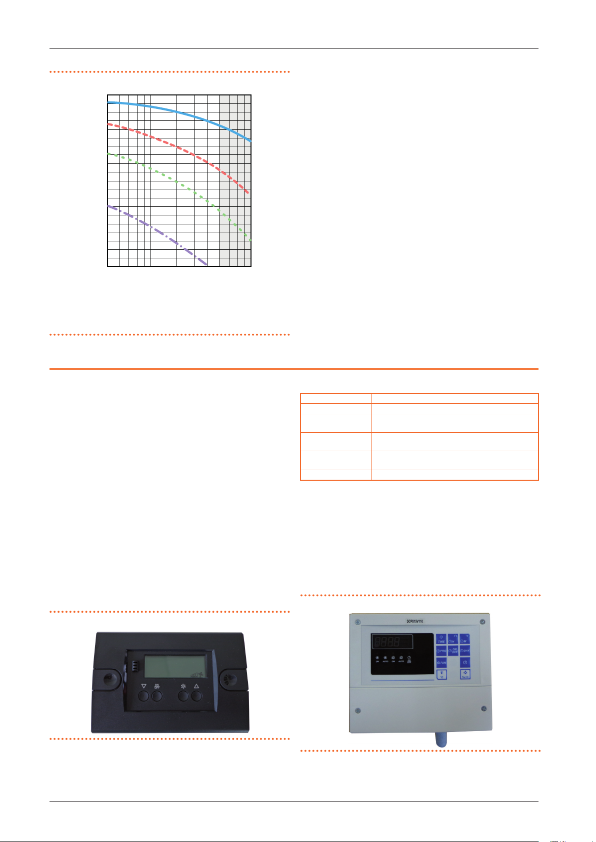
graph in which it is possible to deduce the exchange eciency
in relation to the air speed (and therefore the air ow rate of the
cooler): the higher the speed, the lower the exchange eciency
(Figure 9.1
p.13
).
12
Cod.: D-MNL053EN 19 MED SDC 008
Rev.: A
AD evaporative coolers
07/06/2019
Page 13
Design manual AD evaporative coolers
100
5
A
B
Figure9.1 Evaporative pack saturation eciency diagram
Moreover, if the crossing speed approaches 3 m/s, the droplets
of water present on the edge of the evaporative packs may be
subject to entrainment, with the consequent introduction of wa-
D
=
1
5
0
m
m
90
1
0
0
ter into the cooled room.
In the case of an AD14 cooler we have:
▶
Net exchange area: 2,7 m²
▶
air ow: 13000 m³/h
▶
speed: 1,33 m/s
The crossing speed designed for the Robur AD units allows a
80
70
60
A Saturation eciency (%)
B Air speed (m/s)
The grey area shows the conditions in which condensation forms.
7
5
5
0
3210.5
4
good exchange eciency of the evaporative pack and a suciently low speed to avoid dragging phenomena of water droplets in the cooling air.
10 CONTROL AND REGULATION SOLUTIONS
The evaporative coolers are available in three dierent versions,
two of which are equipped with an independent basic (ECO) or
advanced (EVO) remote control for each unit, and the third (SC)
suitable for the centralised management of a system composed
of up to 30 units, to be associated with a centralised control system, supplied by Robur.
The three versions can be summarized as follows:
▶
AD14/AD20 ECO: equipped with the basic ECO remote control (Paragraph 10.1
▶
AD14/AD20 EVO: equipped with the advanced EVO remote
control (Paragraph 10.2
▶
AD14/AD20 SC: without individual remote control, but designed for a centralised control (Paragraph 10.3
p.13
).
p.13
).
p.14
).
The SC versions can be equipped with two dierent types of
centralized control:
▶
centralized control via SC bus
▶
centralized control via SC bus with Modbus interface for any
external supervision system (e.g. BMS)
10.1 ECO BASIC REMOTE CONTROL
Figure10.1 ECO basic remote control
Table10.1 ECO control technical specications
Mounting on the wall or on an electric box mod. 503
Frontal protection IP00
Operating conditions
Relative environment
humidity
Connections
Display 4 digits display + 10 icons + LED
Ambient temperature -10/+60 °C
Storage temperature -20/+70 °C
20÷80%, non condensing
screw terminals for wires with a maximum cross-sec-
tion of 4 mm² and 2,5 mm²
The features of the ECO basic remote control are:
▶
Turning the appliance on and o.
▶
Cooling/ventilation selection.
▶
Ventilation speed selection (3 levels).
▶
Diagnostics of any faults.
Refer to Figure 8.1
p.12
for the wiring diagram.
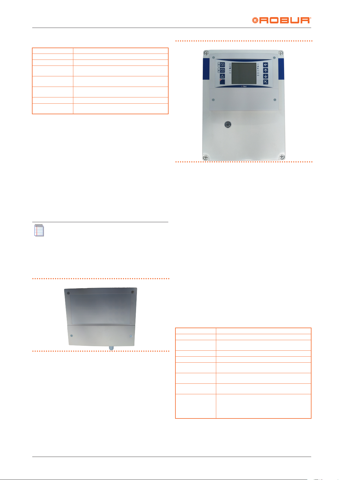
10.2 EVO ADVANCED REMOTE CONTROL
Figure10.2 EVO advanced remote control
Cod.: D-MNL053EN 19 MED SDC 008
Rev.: A
AD evaporative coolers
07/06/2019
13
Page 14
AD evaporative coolers
Table10.2 EVO control technical specications
Enclosure plastic box, dimensions: 180x150x65 mm
Data storage on EEPROM memory
Frontal protection IP54
Operating conditions
Relative environment
humidity
Connections
Display 4 digits display + 10 icons + LED
Inputs
Ambient temperature -10/+60 °C
Storage temperature -20/+70 °C
20÷80%, non condensing
screw terminals for wires with a maximum cross-sec-
tion of 4 mm² and 2,5 mm²
1 input for temperature and humidity digital sensor
(0÷99 rH, precision at 25 °C: ± 3% FS).
The features of the EVO advanced remote control are:
▶
Automatic/manual operation selection.
▶
Cooling/ventilation selection.
▶
Automatic or manual selection of the ventilation speed (3
levels).
▶
Room temperature detection by integrated thermostat.
▶
Ambient humidity detection by integrated humidistat.
▶
Automatic operation based on the setpoint.
▶
Daily programming of the operating time schedule.
▶
Diagnostics of any faults.
The EVO control, compared to the ECO, can provide automatic control of the unit, thanks to the temperature and humidity
probes, and can adjust the fan speed accordingly to the 3 levels
available. With the EVO command it is also possible to set a daily
time schedule, as it is also possible to set the cooling or ventilation only mode.
The automatic ventilation operating mode can only be
selected if the temperature and humidity probe is correctly connected to the control.
Refer to Figure 8.1
p.12
for the wiring diagram.
10.3 CENTRALIZED CONTROL
Figure10.3 OCDS009 network card
Figure10.4 OCDS010/OCDS011 centralized control
This solution allows to centrally manage plants composed of
several units (up to a maximum of 30).
The features of the centralized control are:
▶
Displaying and setting the date and time of network devices.
▶
Displaying of temperature and humidity measured by network devices.
▶
Displaying and changing of temperature and relative humidity setpoints for each individual network device.
▶
Displaying and change network device parameters.
▶
Turning each single network device on and o.
▶
Daily programming of the operating time schedule of the
whole system.
▶
Automatic/manual/o operation selection for each individual network device.
▶
Cooling/ventilation selection for each individual network
device.
▶
Diagnostics of any faults.
In this case, it is not necessary to provide a remote control (ECO/
EVO) for each cooler, but it is sucient to equip each one with
a network card (optional OCDS009), which is equipped with a
temperature and humidity sensor, which also communicates
with a centralised electrical control panel via SC bus (optional
OCDS010) and possibly also with an external supervisor (for example a BMS) via Modbus (optional OCDS011).
Table10.3 OCDS009 network card technical specications
Power supply 230 V AC ± 10%
Consumption 5 VA
Enclosure
Data retention on EEPROM memory
Protection IP54
Operating conditions
Relative environment
humidity
Connections
Inputs
plastic box, dimensions: 180x150x65 mm plus humidity
sensor
Ambient temperature -10/+60 °C
Storage temperature -20/+70 °C
20÷80%, non condensing
Screw terminals for cables with a maximum section of
2,5 mm2
1 input for temperature and humidity digital sensor
(0÷99 rH, precision at 25 °C: ± 3% FS).
2 0-10 V inputs:
• I1 = temperature, 0÷50 °C max, precision 5%
• I2 = humidity, 0÷100 rH, precision 5%
14
Table10.4 General electrical control panel (OCDS010/OCDS011)
Cod.: D-MNL053EN 19 MED SDC 008
Rev.: A
AD evaporative coolers
07/06/2019
Page 15
Design manual AD evaporative coolers
technical specications
Power supply 230 V AC ± 10%
Operation eld -50/+150 °C
Consumption 7 VA
Enclosure plastic box, dimensions 300x220x120 mm
Mounting on the wall
Protection IP00 front panel
Operating conditions
Relative environment
humidity
Connections
Display Backlit LCD
Inputs 3 inputs for PTC probe
Outputs ALARM SPTS relay
Serial communication
Ambient temperature -10/+50 °C
Storage temperature -20/+70 °C
30÷80%, non condensing
Screw terminals for cables with a maximum section of
2,5 mm2
1 RS-485 serial port for SC bus. The maximum network
length is 1000 m
1 TTL serial interface
Only for OCDS011: 1 RS-485 serial port for Modbus
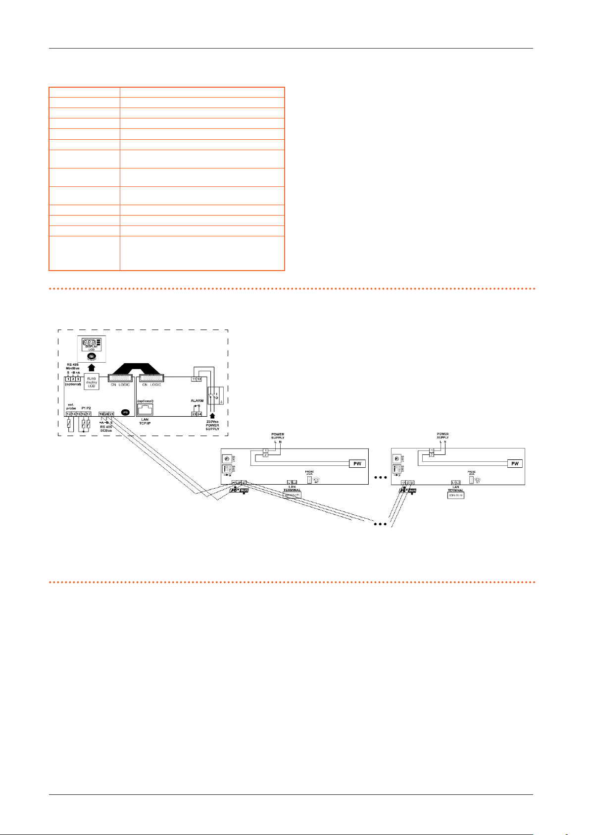
Figure10.5 Connection of network cards to the central control panel
To use this control mode, it is essential that each cooler (up
to a maximum of 30) is equipped with the OCDS009 network
card and that they are connected as an alternative to either the
OCDS010 or OCDS011 control panel (the latter if connection to
the Modbus network is required).
Figure 10.5
p. 15
below shows the wiring diagram for connecting the network cards to the control panel (OCDS010 or
OCDS011).
1
1 General electrical control panel (OCDS010/OCDS011)
2 Electronic board with temperature and humidity sensor (OCDS009)
2 3
3 Electronic board with temperature and humidity sensor (OCDS009)
Cod.: D-MNL053EN 19 MED SDC 008
Rev.: A
AD evaporative coolers
07/06/2019
15
Page 16
AD evaporative coolers
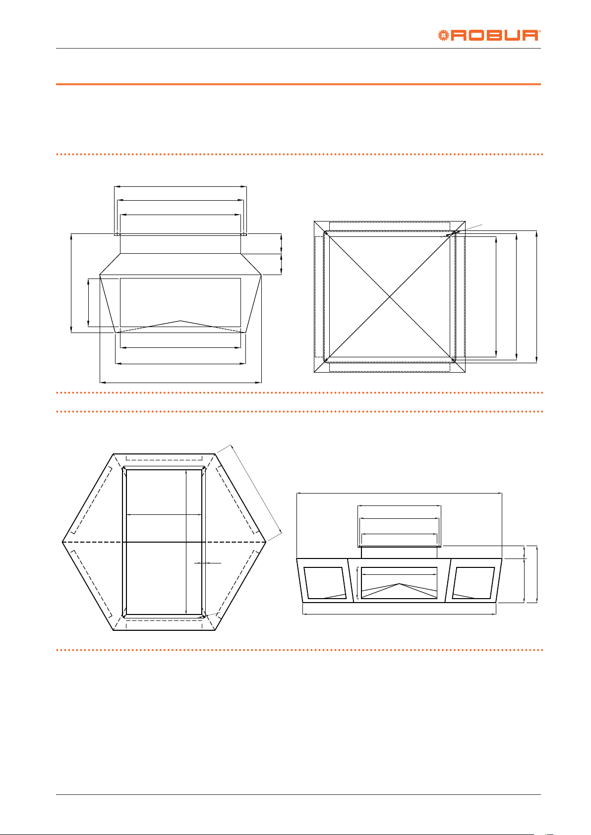
660
495
11 DIFFUSION PLENUMS
For a more homogeneous diusion of the cooled air in the room,
diusion plenums are available as an option:
11.1 DIMENSIONS
Figure11.1 4-way plenum ODFF002 dimensions
630
600
100
105
250
600
650
805
▶
4-way diusion plenum for AD14
▶
6-way diusion plenum for AD20
Ø8
600
630
660
Figure11.2 6-way plenum ODFF003 dimensions
590
1185
30
Ø8
808.3
250
1630.7
660
630
590
600
1532.1
100350
450
16
Cod.: D-MNL053EN 19 MED SDC 008
Rev.: A
AD evaporative coolers
07/06/2019
Page 17
Design manual AD evaporative coolers
630
D
1150
1150
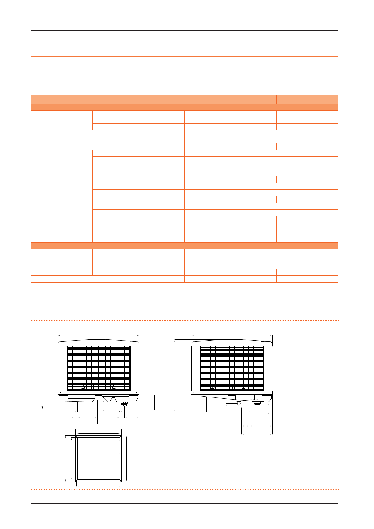
12 TECHNICAL DATA AND DIMENSIONS
12.1 TECHNICAL CHARACTERISTICS
Table12.1 Technical characteristics
AD14 AD20
Installation data
at maximum speed m³/h 13000 20000
Air ow
fan type - assiale
maximum useful pressure head Pa 80
water consumption l/h 43 (1) 64 (1)
Water inlet
Water drain
Humidifying panel
Dimensions
Weight
Electrical specications
Power supply
Electrical power absorption nominal kW 1,10 1,80
maximum power consumption A 4,8 7,0
(1) Test conditions: outdoor temperature 33 °C, relative humidity 60%.
at average speed m³/h 9700 15000
at minimum speed m³/h 6500 10000
type - M
thread “ 3/8
type - M
diameter (Ø) mm 60
surface m² 2,7 3,4
thickness mm 100
saturation eciency % 88
width mm 1150 1650
depth mm 1150
height mm 1050
Air delivery outlet
width mm 600 1185
height mm 600 590
weight kg 67 120
in operation kg 88 146
voltage V 230
type - single-phase
frequency Hz 50
12.2 DIMENSIONS
Figure12.1 AD14 dimensions
A Water inlet 3/8" M
B Water drain 60 mm M
C Electrical panel
D
C
A
170
280
38
555
320
660
600
B
209
65
595
600
660
630
D-D
1050
A
243
86
C
117
B
80
110
217112
440
Cod.: D-MNL053EN 19 MED SDC 008
Rev.: A
AD evaporative coolers
07/06/2019
17
Page 18
AD evaporative coolers
1650
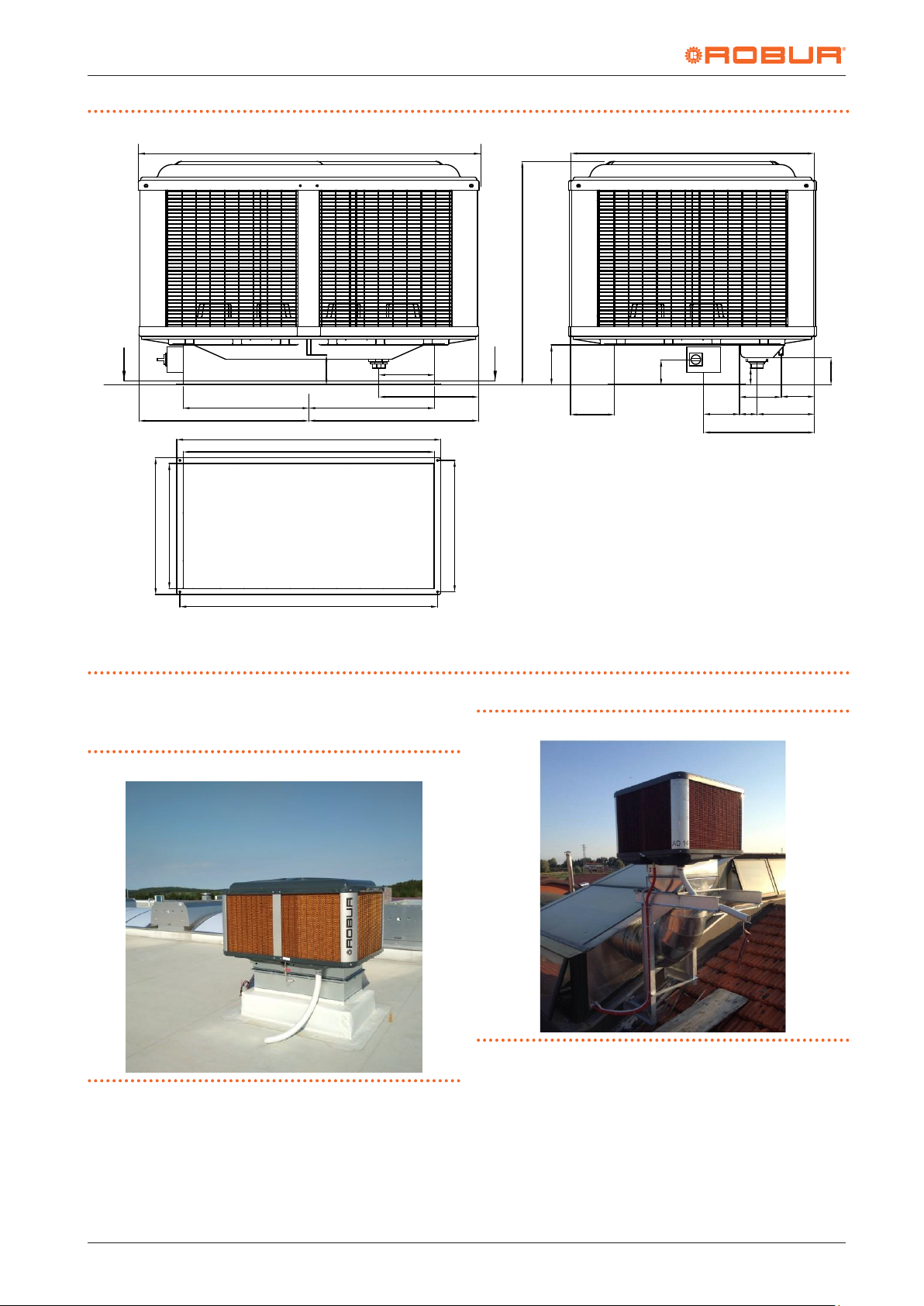
Figure12.2 AD20 dimensions
1150
1050
D
C
592.5 592.5
825
590
660
A
1245
1185
1215
150
A Water inlet 3/8" M
B Water drain 60 mm M
C Electrical panel
12.3 INSTALLATION EXAMPLES
Figure12.3 Installation example
261.5
D
B
530
825
620
189
130
205
C
A
B
80
195
280
85170
530
128
165
D-D
Figure12.4 Installation example
18
Cod.: D-MNL053EN 19 MED SDC 008
Rev.: A
AD evaporative coolers
07/06/2019
Page 19
Design manual AD evaporative coolers
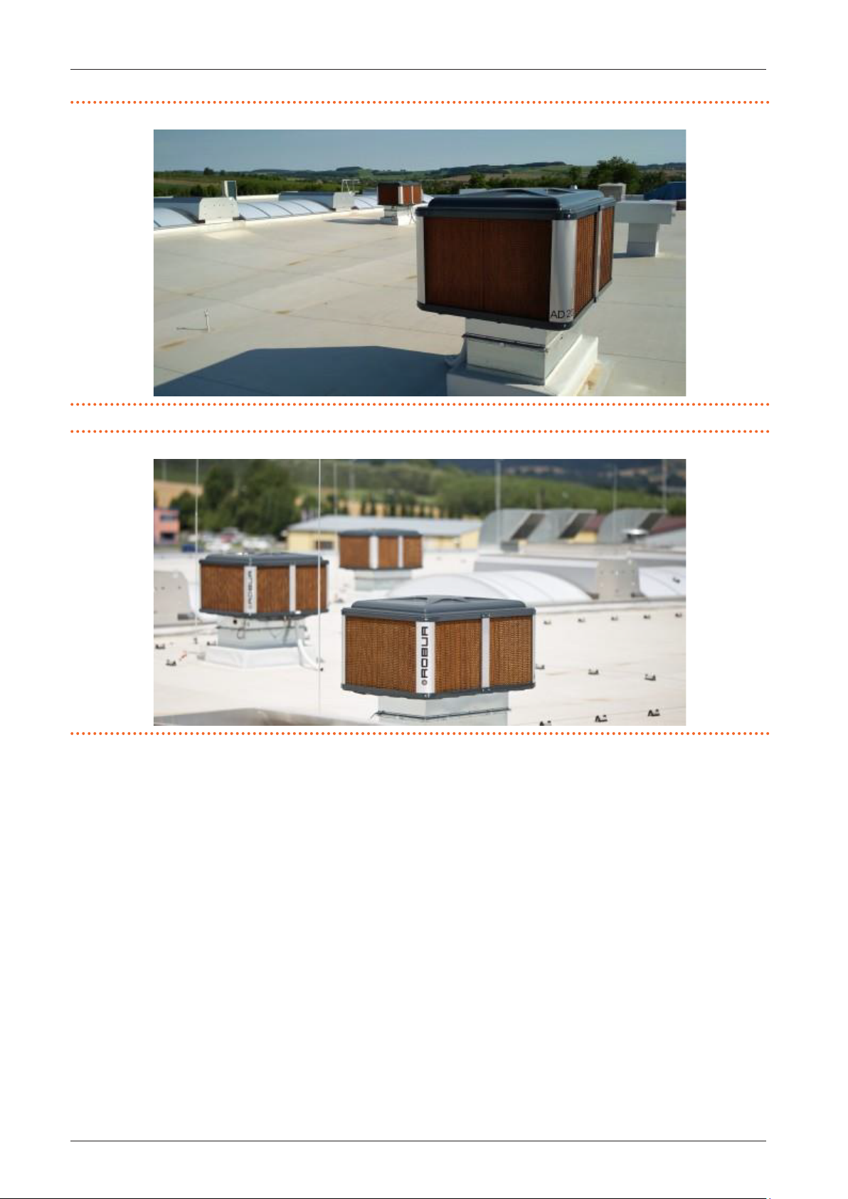
Figure12.5 Installation example
Figure12.6 Installation example
Cod.: D-MNL053EN 19 MED SDC 008
Rev.: A
AD evaporative coolers
07/06/2019
19
Page 20
Robur mission
Robur is dedicated to dynamic progression
in research, development and promotion
of safe, environmentally-friendly, energy-eciency products,
through the commitment and caring
of its employees and partners.
07/06/2019
19 MED SDC 008
Code: D-MNL053EN
Robur S.p.A.
advanced technologies
for climate conditioning
via Parigi 4/6
24040 Verdellino/Zingonia (BG) Italy
+39 035 888111 - F +39 035 884165
www.robur.it [email protected]
Revision: A
 Loading...