

Page 1
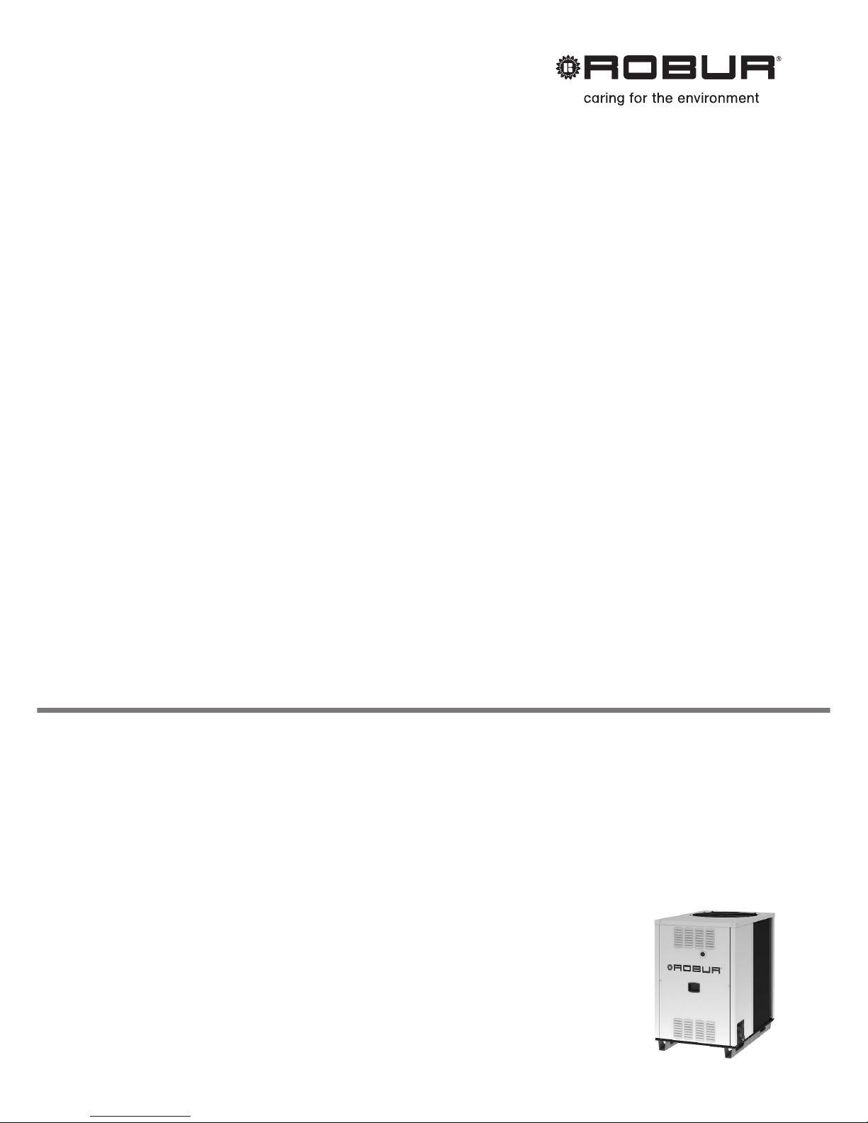
GA Line ACF 60-00 Model
Gas fired absorption chiller
for cooling medium-large areas
Natural gas/LPG fired
Installation, use and
maintenance manual
Page 2

Page 3

INDEX
1. GENERAL WARNINGS ................................................................................................3
2. OVERVIEW AND TECHNICAL DATA..........................................................................5
2.1 OVERVIEW .............................................................................................................5
2.2 GAS FIRED CHILLER OPERATION CYCLE ..........................................................6
2.3 TECHNICAL DATA: ACF60-00 (STANDARD, HR, HT, TK, LB VERSIONS) ..........8
STANDARD VERSION ............................................................................................ 8
HT VERSION.........................................................................................................10
TK VERSION ......................................................................................................... 13
ACF60-00 UNIT INTERNAL PRESSURE DROP (Standard, HT, TK versions) ... 15
LB VERSIONS.......................................................................................................16
ACF60-00 LB UNIT INTERNAL PRESSURE DROP .............................................20
HR VERSION ........................................................................................................21
ACF60-00 HR UNIT INTERNAL PRESSURE DROP OPERATION FOR AIR
CONDITIONING ONLY (NO RECOVERY)............................................................26
ACF60-00 HR HEAT RECOVERY UNIT INTERNAL PRESSURE DROP.............26
2.4 DIMENSIONS ........................................................................................................27
3. INSTALLATION ..........................................................................................................28
3.1 GENERAL RULES.................................................................................................28
3.2 INSTALLATION OF THE UNIT..............................................................................29
4. HYDRONIC AND GAS INSTALLATION.....................................................................33
4.1 WATER PIPING DESIGN AND INSTALLATION ...................................................33
4.2 GAS SUPPLY PIPING ...........................................................................................37
5. ELECTRICAL CONNECTION.....................................................................................38
5.1 POWER SUPPLY AND PUMP WIRING FOR A SINGLE ACF60-00 UNIT ...........38
5.2 POWER SUPPLY AND PUMP WIRING FOR 2 OR MORE ACF60-00 UNITS......40
5.3 CONTROL SWITCH WIRING AND THERMOSTAT LOCATION...........................41
5.4 ACF60-00 WIRING ................................................................................................42
5.5 DDC CONNECTION ..............................................................................................43
6. START-UP AND ADJUSTMENT ................................................................................51
6.1 FILLING THE WATER PIPING ..............................................................................51
6.2 GAS PRESSURE ADJUSTEMENT .......................................................................54
6.3 CHILLED WATER TEMPERATURE REGULATION..............................................56
7. SERVICING AND MAINTENANCE.............................................................................57
8. ADAPTING TO ANOTHER GAS.................................................................................59
9. SPARE PARTS...........................................................................................................60
10. APPENDIX ..................................................................................................................68
TABLE OF OPERATING CODES GENERATED BY ELECTRONIC BOARD (firmware
version 3.027) .................................................................................................................72
Page 4
Installation, Start-Up, Adjustment and Maintenance Manual
2
Carefully read the information contained in this manual. It contains important instructions regarding installation,
use and maintenance safety. Save this manual for any future needs. The manufacturer cannot be held
responsible for any damages from improper, erroneous or irrational use.
With the aim of continuously improving the quality of our products, manufacturer reserves the right to change
reported instructions and drawings without any prior notice.
NOTE
Page 5
Installation, Start-Up, Adjustment and Maintenance Manual
3
1. GENERAL WARNINGS
This manual is an integral and essential part of the product and must be given to the owner.
Only qualified technicians, strictly complying with the manufacturer’s instructions and the local standards,
should install this product. The manufacturer will not accept responsibility for personal injuries or property
damage resulting from improper installation.
Qualified technicians are those having specific technical competence in air conditioning and gas appliances
according to international and national standards.
This appliance must be used exclusively for its intended purpose. All chilling applications must be in
accordance with the operating specifications of the unit. Any other use is considered improper and,
therefore, dangerous. Steps must be taken to avoid improper use and potential dangers.
The fluids used in the sealed refrigerant circuit may cause health problems if inhaled, ingested or when
allowed to come into contact with the skin. It is recommended that no work be performed on the sealed
refrigerant circuit except by a qualified service technician or engineer. Care should also be taken not to
disturb or handle the valves of the chiller’s sealed refrigerant circuit.
The manufacturer will not accept contractual or non-contractual liability for damages resulting from improper
installation or misuse of the unit or intentional disregard of any of the manufacturer’s instructions.
After unpacking the unit, check the unit for integrity. Due to the potential danger, keep all packaging
materials (plastic bags, polystyrene foam, nails, etc.) away from children.
Before installation, it is recommended that all chilled water and gas supply piping be flushed. If not flushed
prior to installation, residual materials may be left in the piping that could cause improper functioning of the
chiller.
The installation of the appliance must conform to the requirements of the authority having jurisdiction or in
the absence of such requirements, to the latest edition of the National Fuel Gas Code, ANSI Z223.1. If the
unit is installed in Canada, the installation must conform to the Canadian Gas Association Standard CAN1
B149.1 and .2.
The chiller’s electrical connections and grounding must be in accordance with the latest edition of the
National Electrical Codes, ANSI/NFPA No. 70 (CSA Standard C22.1 when installed in Canada) and with
any local codes. To ensure the electrical safety of this appliance, it must be correctly connected to an
efficient grounding system. The manufacturer is not responsible for any damages caused by the failure of
the grounding system.
In the case of failure and/or poor unit performance, shut the unit down in the proper manner, disconnect the
UNIT power supply and close the gas valve. Do not attempt any repair and call a qualified technician for
service. The chiller should also be disconnected when not in use for a prolonged period of time.
The manufacturer’s authorized Service Technicians or authorized Service Engineer (TAC), using only
original replacement parts, must perform repairs to the product. Failure to adhere to this guideline may
compromise the safety of the unit. To ensure the correct operation and efficiency of the unit, it is essential
that qualified service technicians perform annual maintenance in accordance with the manufacturer’s
instructions.
Page 6
Installation, Start-Up, Adjustment and Maintenance Manual
4
If the unit is sold or transferred to another owner, this manual will be provided for use to the new owner
and/or installer.
Under no circumstances should the unit be operated with any safety or electrical component bypassed or defective.
Do not use this appliance if any part has been under water. Immediately call a qualified service
technician to inspect the appliance and to replace any part of the control system and any gas
control, which has been under water.
Before starting the appliance:
A qualified service technician must verify that:
- The electric and gas supplies are the same as indicated on the rating plate
- The fuel supply and water distribution systems are water tight
- The appliance is supplied with the type of fuel for which it is preset
- The gas supply pressure conforms to the pressure indicated on the rating plate
- The gas supply system is appropriately designed for the gas rate needed by the unit, and equipped with
all safety and control devices prescribed by standards in force.
To guarantee the correct operation of the unit and avoid possible failures, ALWAYS turn off the unit by
means of the thermostat or any switch that controls the operation of the unit.
NEVER turn off the unit by shutting off the power supply.
Page 7
Installation, Start-Up, Adjustment and Maintenance Manual
5
2. OVERVIEW AND TECHNICAL DATA
2.1 OVERVIEW
The High Efficiency Chillers ACF60-00 series are water chillers, equipped with an air-cooled condenser and
designed for outdoor installation. The absorption cooling cycle is based upon a solution of water and
ammonia for the production of chilled water (temperature of chilled water is given by Technical Tables).
The chilling system is fed by thermal energy provided by a gas burner, therefore the required electric energy
is limited to driving the fan and pump motors (the only mechanical moving components of the unit). The
evacuation of combustion gases occurs by mixing them with condenser air using an axial fan of the
appliance. The combustion fuel is Natural Gas or LPG.
The STANDARD and HT versions are designed for the commercial and industrial air-conditioning
applications in the hot climate areas.
The TK versions are designed for the air-conditioning and refrigeration of technological applications (for
example, in the industrial process, that could require chilled water up to 24h a day).
The LB versions are designed for the low temperature refrigeration applications (for example cold rooms for
food conservation).
ACF60-00 HR, “Heat Recovery”. This is an ACF60-00 with a heat recovery system able to provide 60,500
Btu/hr of nominal cooling capacity when operating without the heat recovery system. With the heat recovery
system, it can obtain a cooling capacity of 61,234 Btu/hr, at the same time providing 86,400 Btu/hr of heating
capacity.
For further information see next paragraph, technical data.
ACF60-00 units are Natural Gas or LPG fired and supplied with 208 - 230V 60Hz single-phase electrical
power.
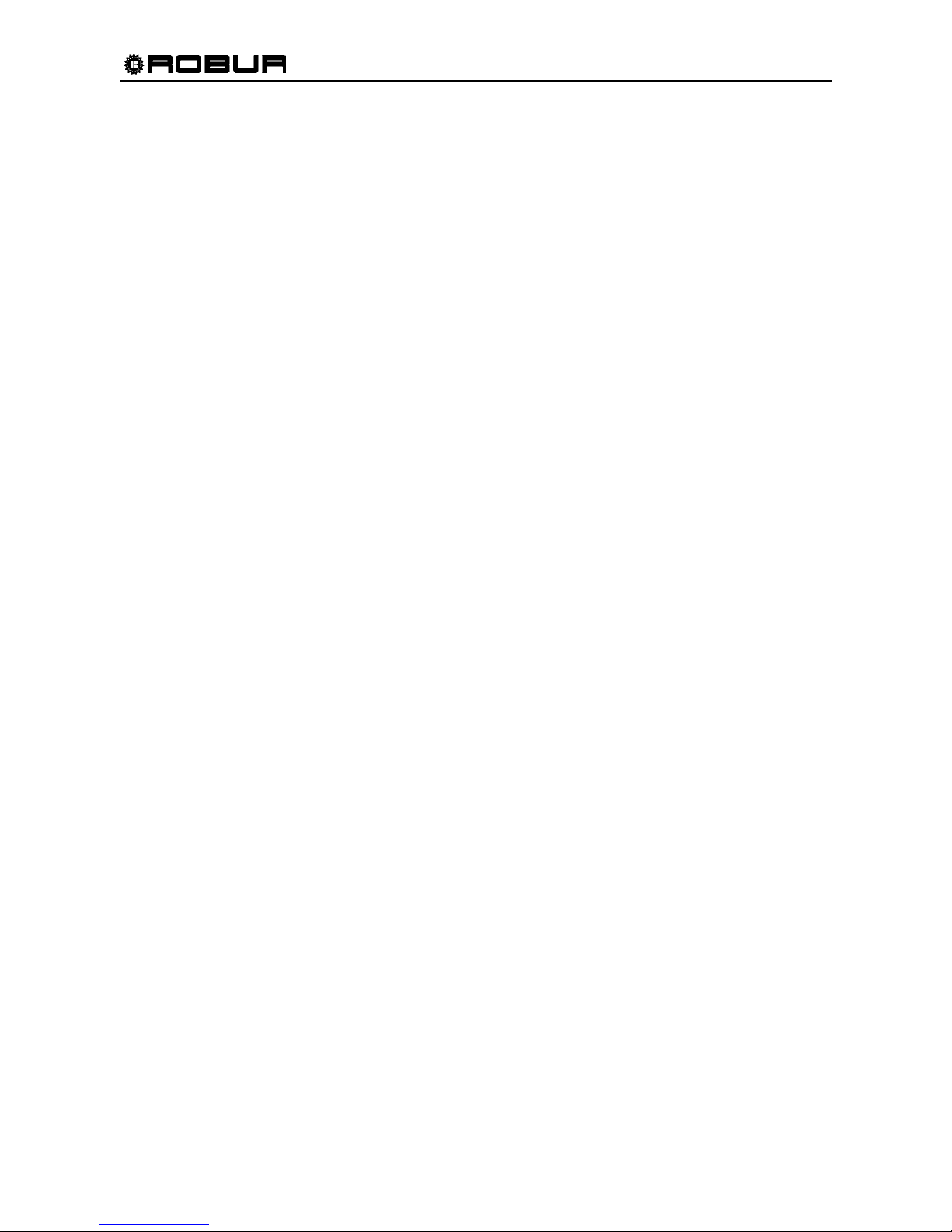
ACF60-00 units could be controlled by DDC - Direct Digital Controller
(available as Optional). DDC can control up to 16 single chillers.
Figure 1 - Direct Digital Controller
CHILLER’S CONTROL AND SAFETY DEVICES
Electronic Control Board with integrated microprocessor controls the operation of the chiller.
High Temperature Limit Switch (manual reset) is located at the generator wall above the combustion
chamber; the switch opens if the generator's sidewall temperature exceeds 330°F; the switch is manual
reset. The switch can be reset when the generator sidewall temperature drops below 280°F.
Safety Relief Valve on the sealed circuit.
Differential Air Pressure Switch on the combustion circuit stops the burner ignition due to insufficient
combustion air flow.
Ignition Control Box controls the burner ignition. Checks the differential air pressure switch and starts the
pre-mixer blower. After 30 seconds of purging, the ignition control box opens the gas valve and starts the
ignition transformer sparking at the burner for 8 seconds. If no flame is detected, the ignition control box will
close the gas valve and retry lighting after an inter-purge period of 30 seconds. The ignition control box will
try a total of three times to light. The unit will stop if no flame has been established or detected after the 3
tries.
Dual Gas Valve: two gas valves in the same housing, electrically controlled, which positively stops gas flow
when either closes.
Page 8
Installation, Start-Up, Adjustment and Maintenance Manual
6
Flow Switch monitors the chilled water flow and shuts down the unit when the water flow stops or drops to
an insufficient level.
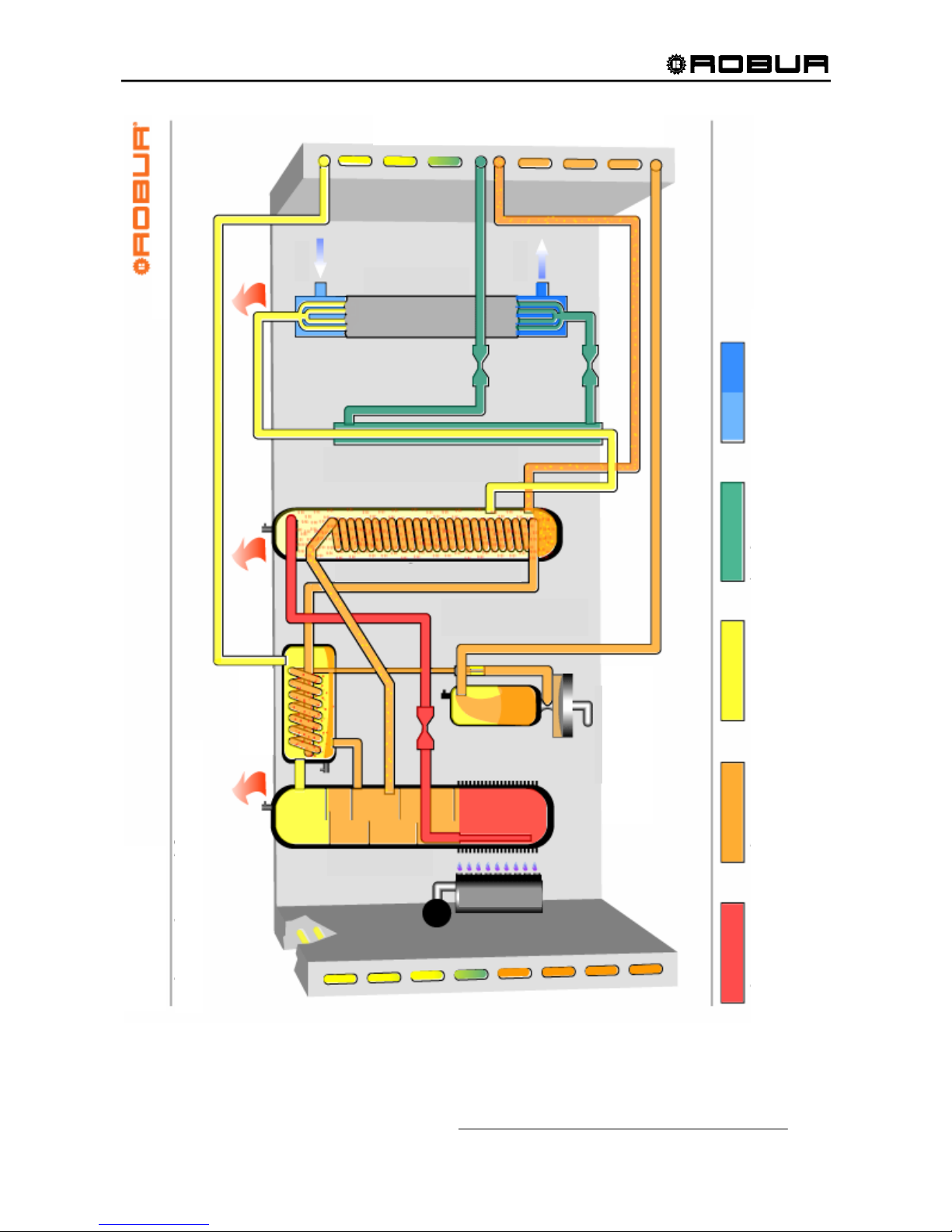
2.2 GAS FIRED CHILLER OPERATION CYCLE
The fluid used in the cooling cycle is a solution of water and ammonia (see Figure 2). Ammonia is the
refrigerant and water is the absorbing fluid. In the chiller’s generator, the ammonia-water solution is heated
to boiling by a burner producing both a vapor with a strong concentration of ammonia and a liquid solution
with a low concentration of ammonia. Liquid solution with a low concentration of ammonia is called a "weak
solution".
The ammonia vapor passes into the rectifier, which separates the water from the vapor. The hot and
pressurized ammonia vapor exiting the rectifier enters the condenser where it is cooled and changed to a
liquid.
The liquid ammonia is then brought to a lower pressure by means of a restrictor and further cooled in a
“tube-in-tube” refrigerant heat exchanger. Finally, the liquid ammonia is reduced to a pressure of 39 to 60
psig and a temperature lower than 37°F by a second restrictor.
Under this low pressure and temperature condition, liquid ammonia enters the evaporator where the
ammonia evaporates due to heat being removed from water returning from the user's required cooling
application (thermal blowers, fan-coils, etc.) within the chilled water system.
The cold, low-pressure ammonia vapor exiting the evaporator exchanges heat with the liquid ammonia
coming from the condenser in the refrigerant heat exchanger. The ammonia vapor then enters the “solution
cooled absorber” where it comes into contact with "weak solution" from the generator that has been brought
to a low pressure by means of a restrictor.
Inside the “solution cooled absorber” the absorption process starts, i.e. the dilution of ammonia vapor into the
"weak solution". The absorption of ammonia vapor is an exothermic process. (i.e. heat is produced) To have
the vapor completely absorbed by the solution, the solution exiting the “solution cooled absorber” must be
further cooled in a portion of the condenser/absorber coils.
Once the absorption process is complete, the liquid solution contains a high concentration of ammonia, also
called "strong solution". A hydraulically driven, diaphragm solution pump pumps the “strong solution” to the
generator at high pressure.
As the “strong solution” is pumped to the generator, it passes through the coil of the rectifier and the solution
cooled absorber (the GAX section) where it is preheated before entering the generator. The cycle then
starts over.
Page 9
Installation, Start-Up, Adjustment and Maintenance Manual
7
Figure 2– ABSORPTION REFRIGERANT CYCLE
EVAPORATOR
TUBE-IN-TUBE REFRIGERANT
SOLUTION
PUMP
SOLUTION COOLED
A
BSORBER
GENERATOR
RECTIFIER
BURNER
WEAK STRONG REFRIGERANT REFRIGERANT CHILLED
SOLUTION SOLUTION VAPOR LIQUID WATER
CONDENSER / ABSORBER
RESTRICTORS
ACF60-00
Page 10
Installation, Start-Up, Adjustment and Maintenance Manual
8
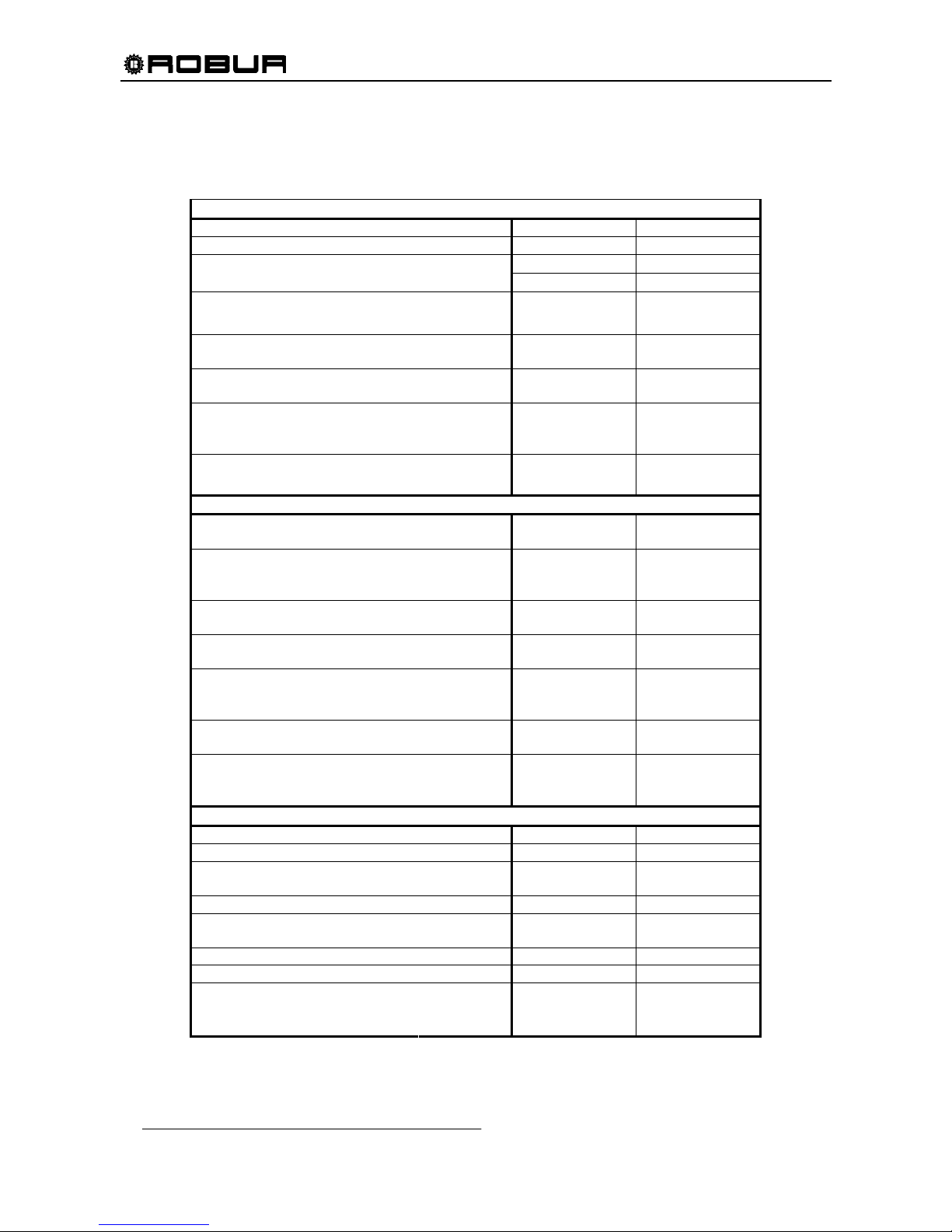
2.3 TECHNICAL DATA: ACF60-00 (STANDARD, HR, HT, TK, LB VERSIONS)
STANDARD VERSION
PERFORMANCE RATINGS
1
UNITS
ACF60-00
Cooling Capacity2 Nominal Btu/hr 60,500
Gas Input (HHV) Nominal Btu/hr 94,900
°F
120
Ambient Operating Temperature
Maximum
Minimum
°F
32
Condenser Air Flow3
Nominal
Minimum
CFM
CFM
6,000
2,000
Inlet (to the unit) Chilled Water
Temperature
Maximum
°F
113
Outlet (to plant) Chilled Water
Temperature
Minimum
°F
37.4
Chilled Water Flow
Nominal
Maximum
Minimum
GPM
12.2
14.1
11.0
Internal Pressure Drop
Feet of Head
psi
g
9.7
4.2
ELECTRICAL RATINGS
Required Voltage, 60 Hz, Single
Phase
4
V 208 - 230
Condenser Fan Motor HP
(Variable Speed)
Full Load / Locked Rotor
Nominal
-
A
1/2
3.1 / 6.2
Hydraulic Pump Motor HP
Full Load / Locked Rotor
Nominal
-
A
1/2
3.1 / 24.2
Premix Blower Motor HP
Full Load / Locked Rotor
Nominal
-
A
1/50
.55 / .75
Total Electrical Operating
Consumption
5
(Unit only)
kW .75
Minimum Circuit Ampacity
(MCA) (Unit only)
A 8.0
Maximum Over Current
Protection (MOCP)
Qty (2) - Field Supplied
A 10.9
PHYSICAL DATA
Refrigerant Type - R717
Unit Chilled Water Volume6 Gallons 0.79
Chilled Water Entering and
Leaving Connections
7
FPT 1” 1/4
Gas Inlet Connection FPT 1/2
Electrical Entrance Knockouts,
Diameter
Inches 7/8
Shipping Weight Pounds 795
Operating Weight Pounds 750
Width 331/
2
Length 481/2
Dimensions
Height
Inches
50
3
/4
Table 1 – ACF60-00 TECHNICAL DATA
Page 11
Installation, Start-Up, Adjustment and Maintenance Manual
9
Notes:
1. All illustrations and specifications contained herein are based on the latest information available at the time of publication approval.
Robur reserves the right to make changes at any time without notice, in materials, specifications, and models or to discontinue
models.
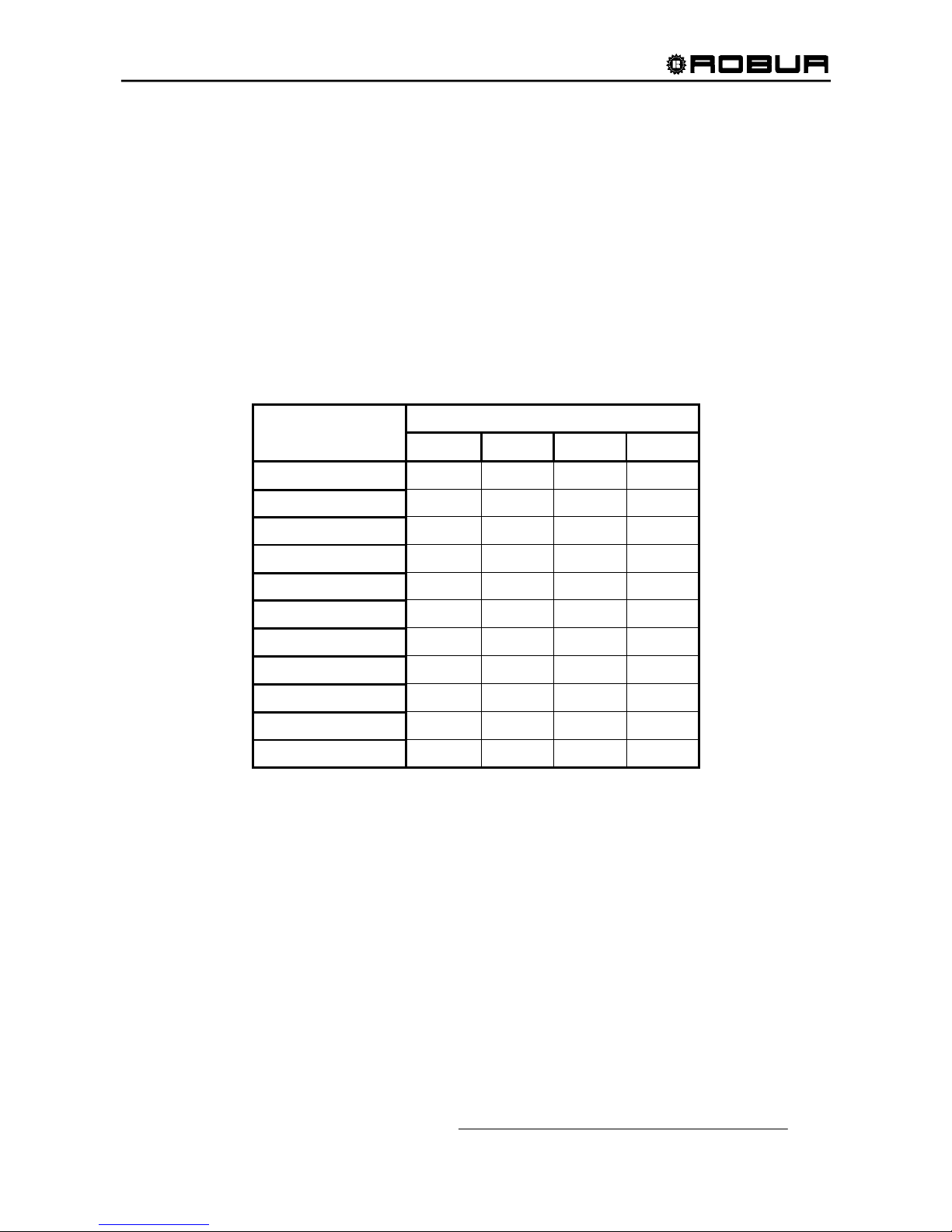
2. Capacity at standard conditions of 95°F ambient temperature. Chilled water Outlet temperature 45°F, chilled water Inlet
temperature 55°F. Actual capacity will vary with ambient (condenser) air temperature and leaving water temperature. Capacity
characteristics are shown in the table below. Interpolations between tabled values are permissible, but do not extrapolate. For
capacities at ambient temperatures higher than in table, contact Robur or your authorized distributor.
3. Fan speed is reduced when external temperature is less than 91.4°F.
4. Units are factory-wired for 208-230 volts operation.
5. May vary by ±10% as a function of both power supply and electrical motor input tolerance.
6. "Chilled Water" refers to a solution of quality tap water and 10% by volume of inhibited permanent antifreeze. Higher antifreeze
concentrations may be required in certain applications.
7. Mono-ethylene glycol causes corrosion phenomenon in galvanized metal pipes.
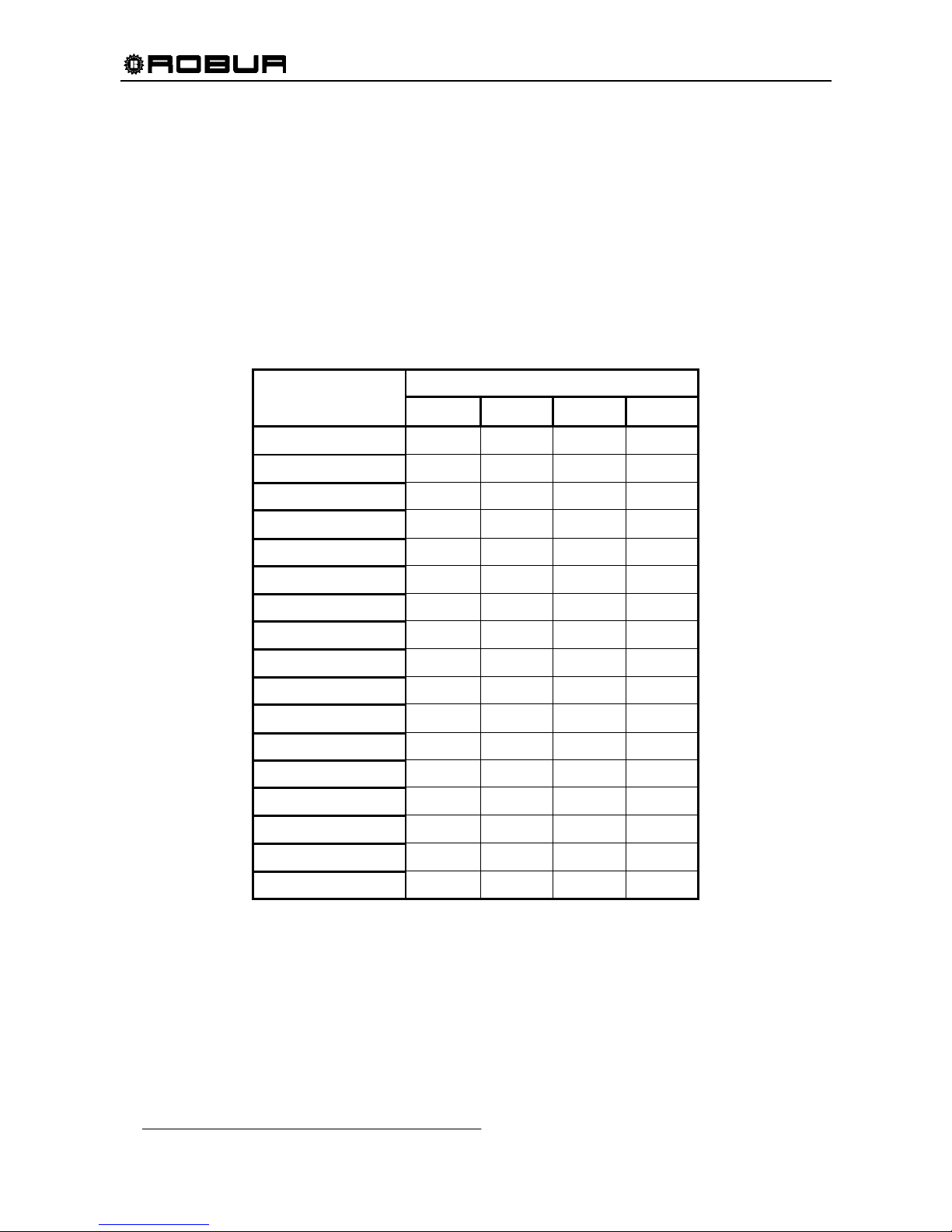
COOLING CAPACITY in Btu/hr
Table 2 – ACF60-00 COOLING CAPACITY
OUTLET CHILLED WATER (°F)
AMBIEN T AI R
TEMPERATURE (°F)
37.4 41.0 44.6 48.2
32
59,307 59,912 61,123 62,323
41
59,307 59,912 61,123 62,333
50
59,307 59,912 61,123 62,323
59
59,307 59,912 61,123 62,333
68
59,307 59,912 61,123 62,323
77
58,701 59,912 61,123 62,333
86
54,465 59,307 61,123 62,333
95
40,546 52,650 60,517 61,727
104
- - 53,255 56,281
113
- - 40,546 47,203
120
- - - 39,336
Page 12
Installation, Start-Up, Adjustment and Maintenance Manual
10
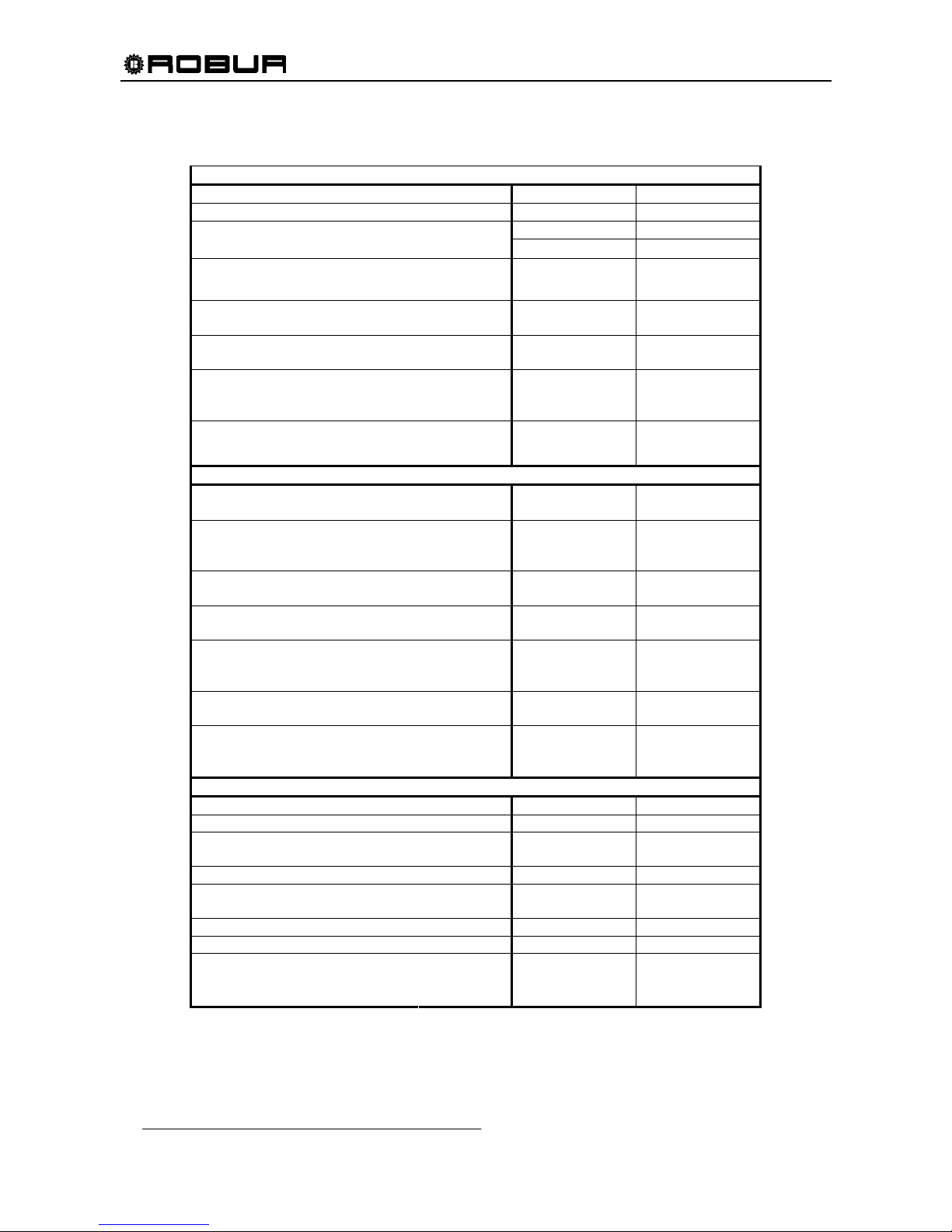
HT VERSION
PERFORMANCE RATINGS
1
UNITS
ACF60-00 HT
Cooling Capacity2 Nominal Btu/hr 58,400
Gas Input (HHV) Nominal Btu/hr 94,900
°F
131
Ambient Operating Temperature
Maximum
Minimum
°F
32
Condenser Air Flow3
Nominal
Minimum
CFM
CFM
6,000
2,000
Inlet (to the unit) Chilled Water
Temperature
Maximum
°F
113
Outlet (to plant) Chilled Water
Temperature
Minimum
°F
41
Chilled Water Flow
Nominal
Maximum
Minimum
GPM
11.8
14.1
11.0
Internal Pressure Drop
Feet of Head
psi
g
9.1
3.9
ELECTRICAL RATINGS
Required Voltage, 60 Hz, Single
Phase
4
V 208 - 230
Condenser Fan Motor HP
(Variable Speed)
Full Load / Locked Rotor
Nominal
-
A
1/2
3.1 / 6.2
Hydraulic Pump Motor HP
Full Load / Locked Rotor
Nominal
-
A
1/2
3.1 / 24.2
Premix Blower Motor HP
Full Load / Locked Rotor
Nominal
-
A
1/50
.55 / .75
Total Electrical Operating
Consumption
5
(Unit only)
kW .75
Minimum Circuit Ampacity
(MCA) (Unit only)
A 8.0
Maximum Over Current
Protection (MOCP)
Qty (2) - Field Supplied
A 10.9
PHYSICAL DATA
Refrigerant Type - R717
Unit Chilled Water Volume6 Gallons 0.79
Chilled Water Entering and
Leaving Connections
7
FPT 1” 1/4
Gas Inlet Connection FPT 1/2
Electrical Entrance Knockouts,
Diameter
Inches 7/8
Shipping Weight Pounds 860
Operating Weight Pounds 816
Width 331/
2
Length 481/2
Dimensions
Height
Inches
50
3
/4
Table 3 – ACF60-00 HT TECHNICAL DATA
Page 13

Installation, Start-Up, Adjustment and Maintenance Manual
11
Notes:
1. All illustrations and specifications contained herein are based on the latest information available at the time of publication approval.
Robur reserves the right to make changes at any time without notice, in materials, specifications, and models or to discontinue
models.
2. Capacity at standard conditions of 95°F ambient temperature. Chilled water Outlet temperature 45°F, chilled water Inlet
temperature 55°F. Actual capacity will vary with ambient (condenser) air temperature and leaving water temperature. Capacity
characteristics are shown in the table below. Interpolations between tabled values are permissible, but do not extrapolate. For
capacities at ambient temperatures higher than in table, contact Robur or your authorized distributor.
3. Fan speed is reduced when external temperature is less than 91.4°F.
4. Units are factory-wired for 208-230 volts operation.
5. May vary by ±10% as a function of both power supply and electrical motor input tolerance.
6. "Chilled Water" refers to a solution of quality tap water and 10% by volume of inhibited permanent antifreeze. Higher antifreeze
concentrations may be required in certain applications.
7. Mono-ethylene glycol causes corrosion phenomenon in galvanized metal pipes.
Page 14
Installation, Start-Up, Adjustment and Maintenance Manual
12
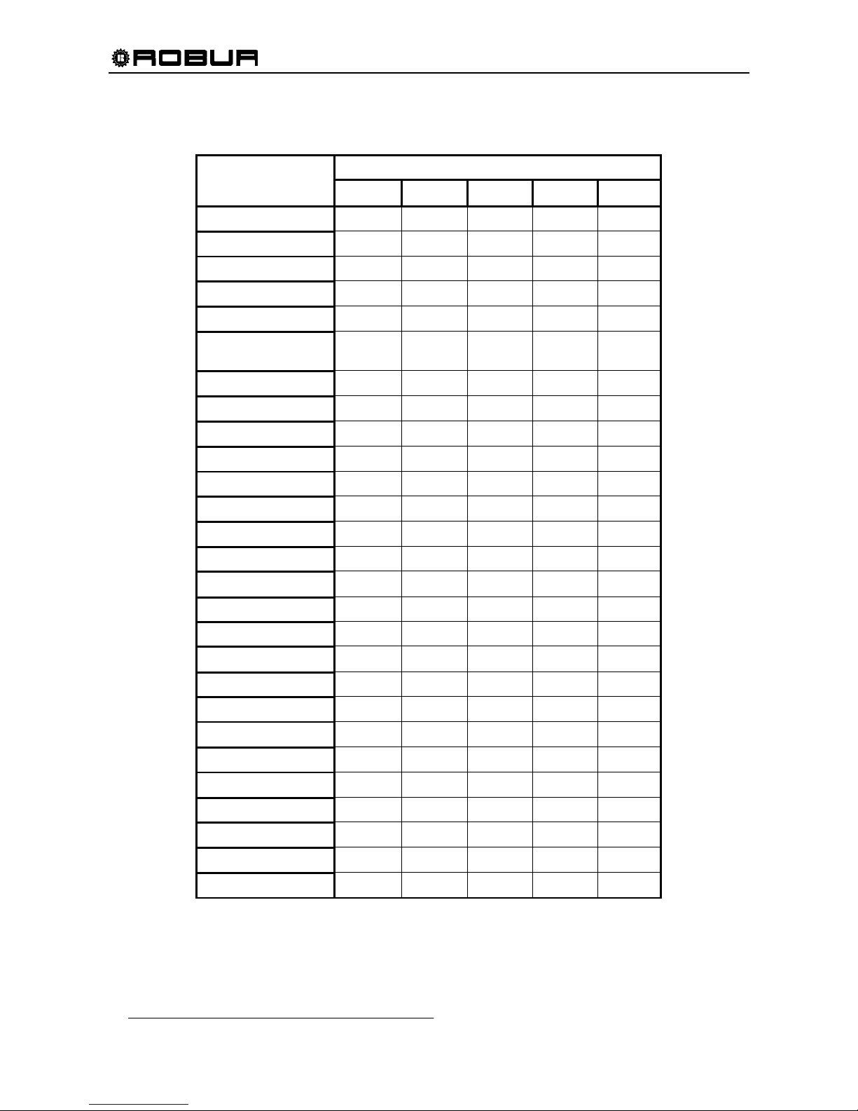
COOLING CAPACITY in Btu/hr
Table 4 – ACF60-00 HT COOLING CAPACITY
OUTLET CHILLED WATER (°F)
AMBIEN T AI R
TEMPERATURE (°F)
41.0 44.6 50.0 54.5 57.2
32.0
59,637 59,637 59,637 59,637 60,222
35.6
59,637 59,637 59,637 59,637 60,222
39.2
59,637 59,637 59,637 59,637 60,222
42.8
59,637 59,637 59,637 59,637 60,222
46.4
59,637 59,637 59,637 59,637 60,222
50.0
59,637 59,637 59,637 59,637 60,222
53.6
59,637 59,637 59,637 59,637 60,222
57.2
59,637 59,637 59,637 59,637 60,222
60.8
59,637 59,637 59,637 59,637 60,222
64.4
59,637 59,637 59,637 59,637 60,222
68.0
59,637 59,637 59,637 59,637 60,222
71.6
59,637 59,637 59,637 59,637 60,222
75.2
59,637 59,637 59,637 59,637 60,222
78.8
59,053 59,637 59,637 59,637 60,222
82.4
59,053 59,637 59,637 59,637 60,222
86.0
59,053 59,637 59,637 59,637 60,222
89.6
57,883 59,637 59,637 59,637 60,222
93.2
56,129 59,053 59,053 59,053 59,637
95.0
54,960 58,368 58,468 59,053 59,637
96.8
53,791 57,883 58,468 58,468 59,637
100.4
50,867 56,714 57,883 57,883 59,053
104.0
47,944 54,375 56,714 57,299 58,468
107.6
- 51,452 54,960 56,714 57,883
111.2
- 47,944 53,206 55,545 56,714
114.8
- - 50,282 53,791 55,545
118.4
- - 46,774 50,867 53,206
131.0
- - - 47,359 50,282
Page 15
Installation, Start-Up, Adjustment and Maintenance Manual
13
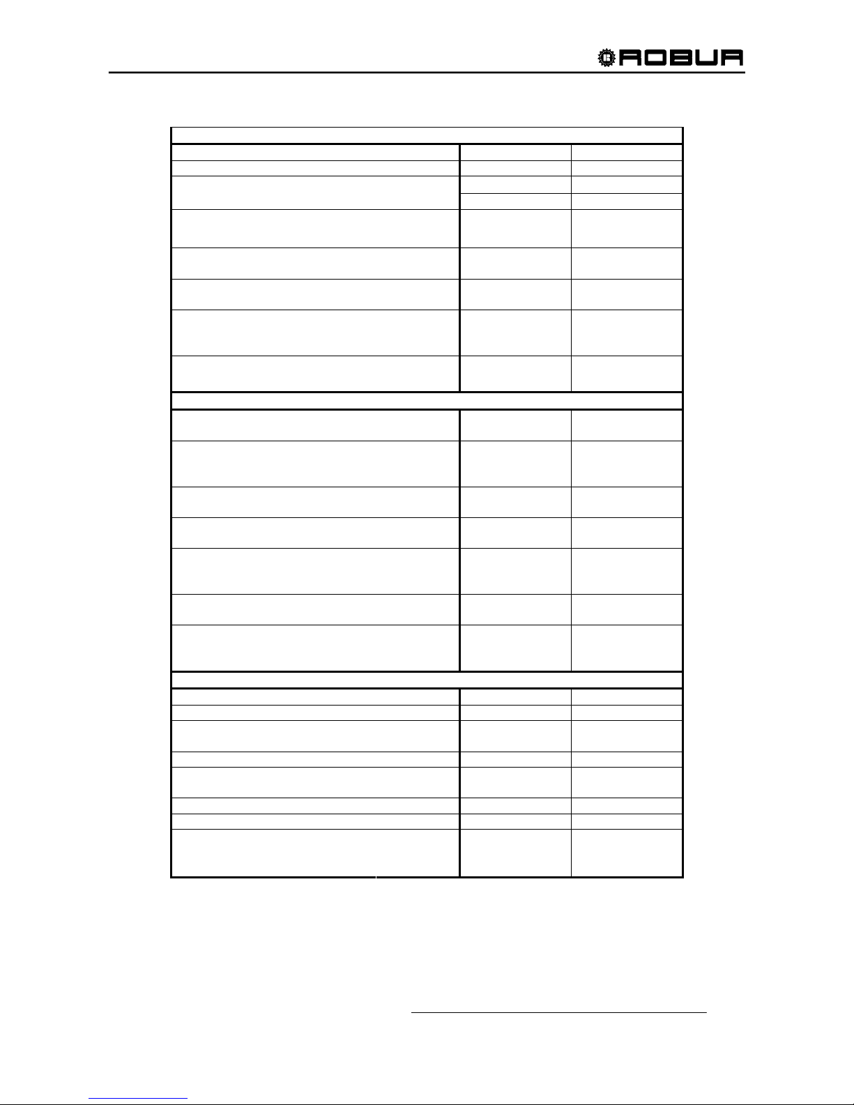
TK VERSION
PERFORMANCE RATINGS1
UNITS
ACF60-00 TK
Cooling Capacity2 Nominal Btu/hr 60,500
Gas Input (HHV) Nominal Btu/hr 94,900
°F
120
Ambient Operating Temperature
Maximum
Minimum
°F
10.4
Condenser Air Flow3
Nominal
Minimum
CFM
CFM
6,000
2,000
Inlet (to the unit) Chilled Water
Temperature
Maximum
°F
113
Outlet (to plant) Chilled Water
Temperature
Minimum
°F
37.4
Chilled Water Flow
Nominal
Maximum
Minimum
GPM
12.2
14.1
11.0
Internal Pressure Drop
Feet of Head
psi
g
9.7
4.2
ELECTRICAL RATINGS
Required Voltage, 60 Hz, Single
Phase
4
V 208 - 230
Condenser Fan Motor HP
(Variable Speed)
Full Load / Locked Rotor
Nominal
-
A
1/2
3.1 / 6.2
Hydraulic Pump Motor HP
Full Load / Locked Rotor
Nominal
-
A
1/2
3.1 / 24.2
Premix Blower Motor HP
Full Load / Locked Rotor
Nominal
-
A
1/50
.55 / .75
Total Electrical Operating
Consumption
5
(Unit only)
kW .75
Minimum Circuit Ampacity
(MCA) (Unit only)
A 8.0
Maximum Over Current
Protection (MOCP)
Qty (2) - Field Supplied
A 10.9
PHYSICAL DATA
Refrigerant Type - R717
Unit Chilled Water Volume6 Gallons 0.79
Chilled Water Entering and
Leaving Connections
7
FPT 1” 1/4
Gas Inlet Connection FPT 1/2
Electrical Entrance Knockouts,
Diameter
Inches 7/8
Shipping Weight Pounds 860
Operating Weight Pounds 816
Width 331/
2
Length 481/2
Dimensions
Height
Inches
50
3
/4
Table 5 – ACF60-00 TK TECHNICAL DATA
Page 16
Installation, Start-Up, Adjustment and Maintenance Manual
14
Notes:
1. All illustrations and specifications contained herein are based on the latest information available at the time of publication approval.
Robur reserves the right to make changes at any time without notice, in materials, specifications, and models or to discontinue
models.
2. Capacity at standard conditions of 95°F ambient temperature. Chilled water Outlet temperature 45°F, chilled water Inlet
temperature 55°F. Actual capacity will vary with ambient (condenser) air temperature and leaving water temperature. Capacity
characteristics are shown in the table below. Interpolations between tabled values are permissible, but do not extrapolate. For
capacities at ambient temperatures higher than in table, contact Robur or your authorized distributor.
3. Fan speed is reduced when external temperature is less than 91.4°F.
4. Units are factory-wired for 208-230 volts operation.
5. May vary by ±10% as a function of both power supply and electrical motor input tolerance.
6. "Chilled Water" refers to a solution of quality tap water and 10% by volume of inhibited permanent antifreeze. Higher antifreeze
concentrations may be required in certain applications.
7. Mono-ethylene glycol causes corrosion phenomenon in galvanized metal pipes.
COOLING CAPACITY in Btu/hr
Table 6 – ACF60-00 TK COOLING CAPACITY
OUTLET CHILLED WATER (°F)
AMBIEN T AI R
TEMPERATURE (°F)
37.4 41.0 44.6 48.2
10.4
71,410 71,410 72,015 72,620
17.6
70,805 70,805 71,410 72,015
24.8
70,200 70,200 70,200 71,410
32.0
69,595 69,595 69,595 70,200
39.2
68,989 68,989 68,989 69,595
46.4
67,779 68,384 68,384 68,989
53.6
67,779 67,779 67,779 68,384
60.8
67,174 67,174 67,779 67,779
68.0
65,964 65,964 67,174 67,174
75.2
64,148 64,148 66,569 66,569
82.4
59,307 61,727 65,358 65,358
89.6
51,439 57,491 62,938 64,148
95.0
41,757 52,650 60,517 62,333
100.4
- - 56,886 59,912
107.6
- - 50,229 55,070
113.0
- - - 49,624
120.0
- - - 42,057
Page 17
Installation, Start-Up, Adjustment and Maintenance Manual
15
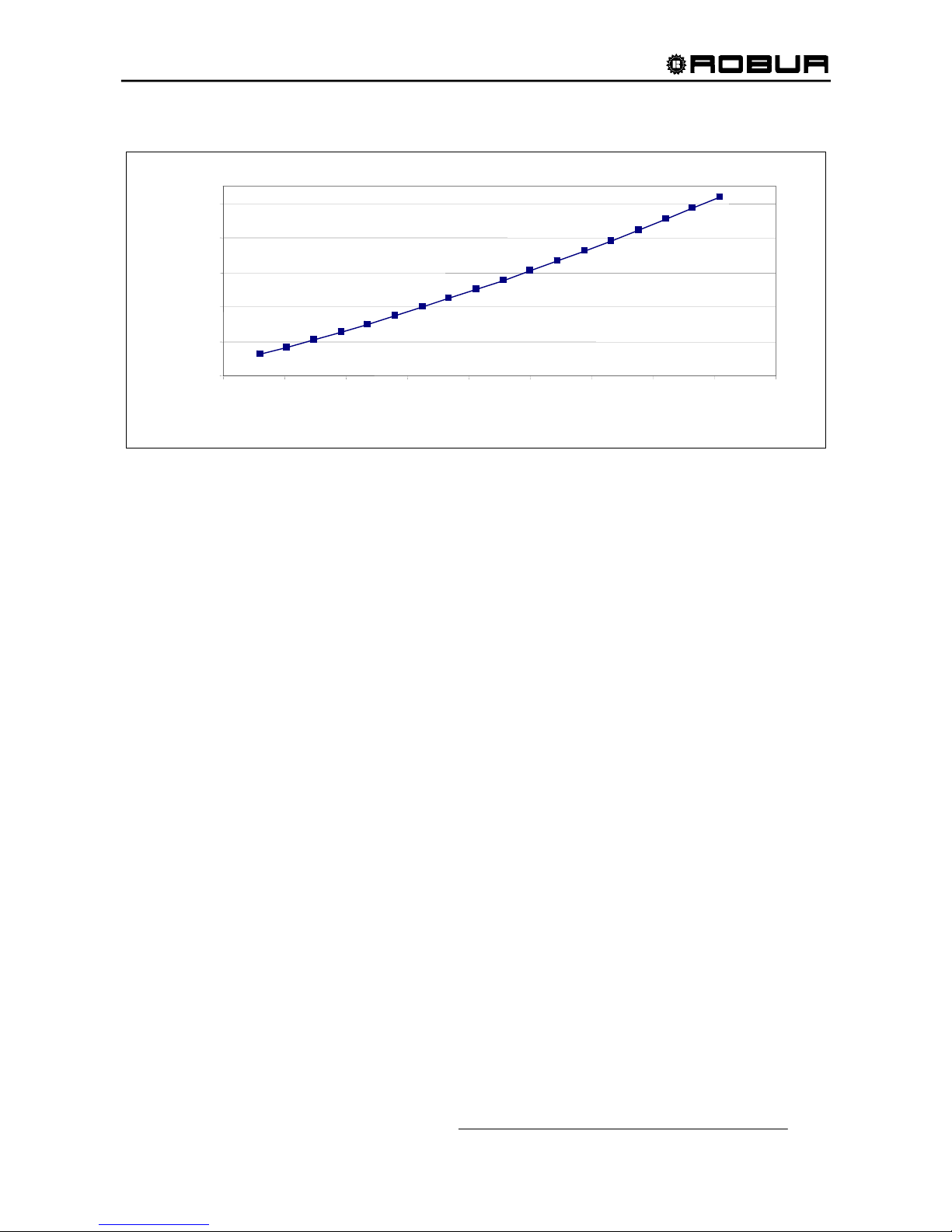
ACF60-00 UNIT INTERNAL PRESSURE DROP (Standard, HT, TK versions)
Graph 1- UNIT PRESSURE DROP AS A FUNCTION OF WATER FLOW, OUTLET WATER TEMPERATURE 44.6 °F
2.00
4.00
6.00
8.00
10.00
12.00
6.00 7.00 8.00 9.00 10.00 11.00 12.00 13.00 14.00 15.00
PRESSURE DROP (FEET OF HEAD)
WATER FLOW (GPM)
ACF60-00,
HT, TK
Page 18
Installation, Start-Up, Adjustment and Maintenance Manual
16
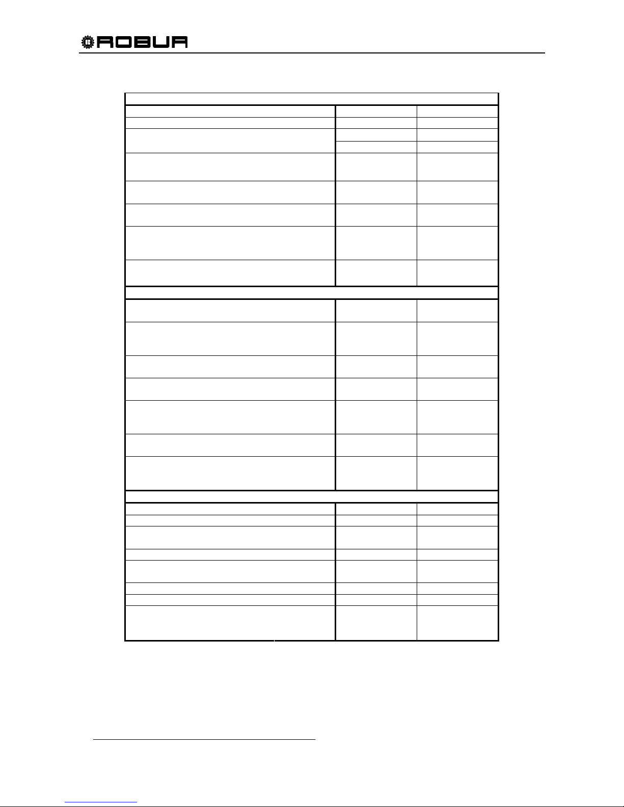
LB VERSIONS
PERFORMANCE RATINGS
1
UNITS
ACF60-00 LB
Cooling Capacity2 Nominal Btu/hr 45,400
Gas Input (HHV) Nominal Btu/hr 94,900
°F
120
Ambient Operating Temperature
Maximum
Minimum
°F
10.4
Condenser Air Flow3
Nominal
Minimum
CFM
CFM
6,000
2,000
Inlet (to the unit) Chilled Water
Temperature
Maximum
°F
113
Outlet (to plant) Chilled Water
Temperature
Minimum
°F
14
Chilled Water Flow
Nominal
Maximum
Minimum
GPM
11.4
12.8
10.1
Internal Pressure Drop
Feet of Head
psi
g
14.1
6.1
ELECTRICAL RATINGS
Required Voltage, 60 Hz, Single
Phase
4
V 208 - 230
Condenser Fan Motor HP
(Variable Speed)
Full Load / Locked Rotor
Nominal
-
A
1/2
3.1 / 6.2
Hydraulic Pump Motor HP
Full Load / Locked Rotor
Nominal
-
A
1/2
3.1 / 24.2
Premix Blower Motor HP
Full Load / Locked Rotor
Nominal
-
A
1/50
.55 / .75
Total Electrical Operating
Consumption
5
(Unit only)
kW .75
Minimum Circuit Ampacity
(MCA) (Unit only)
A 8.0
Maximum Over Current
Protection (MOCP)
Qty (2) - Field Supplied
A 10.9
PHYSICAL DATA
Refrigerant Type - R717
Unit Chilled Water Volume Gallons 0.79
Chilled Water Entering and
Leaving Connections
6
FPT 1” 1/4
Gas Inlet Connection FPT 1/2
Electrical Entrance Knockouts,
Diameter
Inches 7/8
Shipping Weight Pounds 860
Operating Weight Pounds 816
Width 331/
2
Length 481/2
Dimensions
Height
Inches
50
3
/4
Table 7 – ACF60-00 LB TECHNICAL DATA
Page 19

Installation, Start-Up, Adjustment and Maintenance Manual
17
Notes:
1. All illustrations and specifications contained herein are based on the latest information available at the time of publication approval.
Robur reserves the right to make changes at any time without notice, in materials, specifications, and models or to discontinue
models.
2. Capacity at standard conditions of 95°F ambient temperature. Chilled water Outlet temperature (40% mono-ethylene glycol) 23°F,
chilled water Inlet temperature 32°F. Actual capacity will vary with ambient (condenser) air temperature and leaving water
temperature. Capacity characteristics are shown in the table below. Interpolations between tabled values are permissible, but do
not extrapolate. For capacities at ambient temperatures higher than in table, contact Robur or your authorized distributor.
3. Fan speed is reduced when external temperature is less than 91.4°F.
4. Units are factory-wired for 208-230 volts operation.
5. May vary by ±10% as a function of both power supply and electrical motor input tolerance.
6. Mono-ethylene glycol causes corrosion phenomenon in galvanized metal pipes.
Page 20
Installation, Start-Up, Adjustment and Maintenance Manual
18
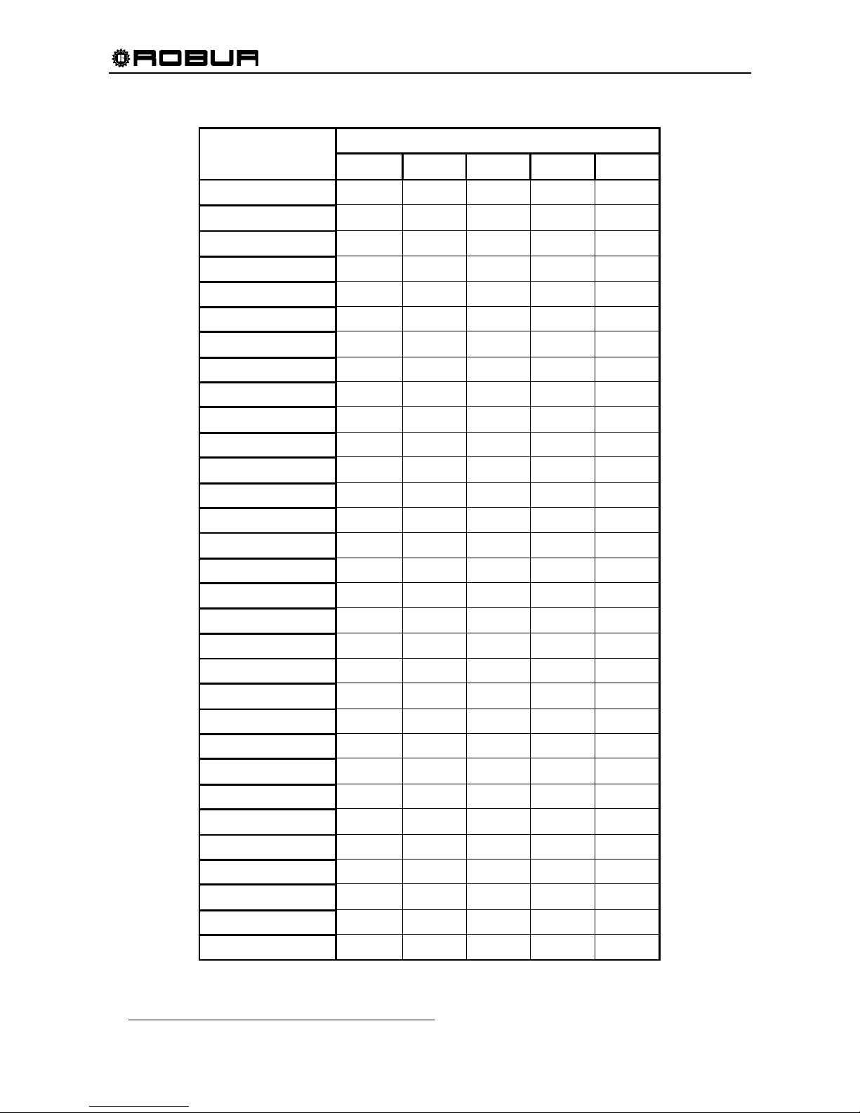
COOLING CAPACITY in Btu/hr
OUTLET CHILLED WATER (°F)
AMBIEN T AI R
TEMPERATURE (°F)
14.0 19.4 23.0 28.4 32.0
23.0
52,007 52,217 52,426 52,801 53,176
24.8
52,007 52,217 52,426 52,801 53,176
26.6
52,007 52,217 52,426 52,801 53,176
28.4
52,007 52,217 52,426 52,801 53,176
30.2
52,007 52,217 52,426 52,801 53,176
32.0
52,007 52,217 52,426 52,801 53,176
33.8
52,007 52,217 52,426 52,801 53,176
35.6
52,007 52,217 52,426 52,801 53,176
37.4
52,007 52,217 52,426 52,801 53,176
39.2
52,007 52,217 52,426 52,801 53,176
41.0
52,007 52,217 52,426 52,801 53,176
42.8
52,007 52,217 52,426 52,801 53,176
44.6
52,007 52,217 52,426 52,801 53,176
46.4
52,007 52,200 52,392 52,784 53,176
48.2
52,007 52,183 52,358 52,767 53,176
50.0
52,007 52,166 52,324 52,750 53,176
51.8
51,965 52,127 52,290 52,733 53,176
53.6
51,904 52,080 52,256 52,716 53,176
55.4
51,822 52,022 52,221 52,699 53,176
57.2
51,718 51,952 52,187 52,681 53,176
59.0
51,588 51,884 52,181 52,678 53,176
60.8
51,430 51,793 52,157 52,666 53,176
62.6
51,241 51,677 52,113 52,644 53,176
64.4
51,020 51,533 52,047 52,610 53,172
66.2
50,763 51,360 51,957 52,563 53,169
68.0
50,469 51,155 51,841 52,503 53,166
69.8
50,134 50,915 51,696 52,423 53,149
71.6
49,757 50,638 51,520 52,314 53,107
73.4
49,334 50,322 51,311 52,174 53,038
75.2
48,864 49,965 51,067 52,002 52,937
77.0
48,343 49,564 50,785 51,795 52,805
Page 21
Installation, Start-Up, Adjustment and Maintenance Manual
19
Table 8 – ACF60-00 LB COOLING CAPACITY
OUTLET CHILLED WATER (°F)
AMBIEN T AI R
TEMPERATURE (°F)
14.0 19.4 23.0 28.4 32.0
78.8
47,771 49,117 50,464 51,551 52,637
80.6
47,143 48,622 50,101 51,267 52,432
82.4
46,458 48,076 49,694 50,941 52,188
84.2
45,713 47,476 49,240 50,571 51,901
86.0
44,905 46,822 48,738 50,155 51,571
87.8
44,033 46,109 48,186 49,690 51,194
89.6
43,093 45,337 47,580 49,174 50,768
91.4
42,084 44,502 46,919 48,605 50,291
93.2
41,003 43,602 46,201 47,981 49,760
95.0
39,847 42,635 45,400 47,299 49,174
96.8
38,614 41,599 44,584 46,557 48,530
98.6
37,302 40,491 43,681 45,753 47,825
100.4
35,907 39,309 42,711 44,884 47,057
102.2
34,428 38,051 41,673 43,949 46,225
104.0
32,863 36,713 40,564 42,945 45,325
105.8
31,208 35,295 39,383 41,869 44,356
107.6
29,461 33,794 38,126 40,720 43,314
109.4
27,620 32,206 36,793 39,496 42,198
111.2
25,682 30,531 35,379 38,193 41,006
113.0
23,645 28,765 33,885 36,810 39,735
120.0
- - 28,004 31,587 35,176
Page 22
Installation, Start-Up, Adjustment and Maintenance Manual
20
ACF60-00 LB UNIT INTERNAL PRESSURE DROP
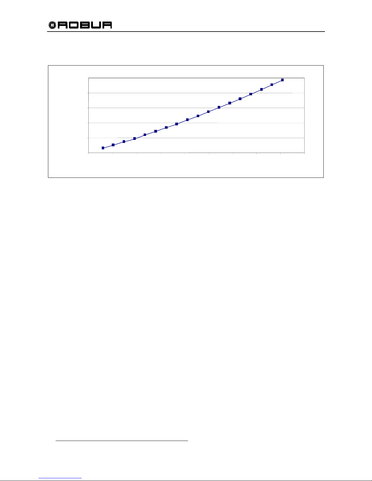
Graph 2 - ACF60-00 LB PRESSURE DROP
8.00
10.00
12.00
14.00
16.00
18.00
6.00 7.00 8.00 9.00 10.00 11.00 12.00 13.00 14.00 15.00
MONOETHYLENE GLYCOL (40%) - WATER FLOW (GPM)
PRESSURE DROP (FEET OF HEAD)
A
CF60-00 LB
Page 23
Installation, Start-Up, Adjustment and Maintenance Manual
21
HR VERSION
PERFORMANCE RATINGS
1
UNITS
ACF60-00 HR
Cooling Capacity
2
Air conditioning only (no recovery)
Nominal Btu/hr 60,500
Cooling Capacity
3
Air conditioning + recovery
Nominal Btu/hr 61,240
Heat Capacity 4 Btu/hr 86,400
Gas Input (HHV) Nominal Btu/hr 94,900
°F
120
Ambient Operating Temperature
Maximum
Minimum
°F
32
Condenser Air Flow 5
Nominal
Minimum
CFM
CFM
6,000
2,000
Inlet (to the unit) Chilled Water
Temperature
Maximum
°F
113
Outlet (to plant) Chilled Water
Temperature
Minimum
°F
37.4
Chilled Water Flow
Nominal
Maximum
Minimum
GPM
12.2
14.1
11.0
Recovery System
Hot Water Flow rate (∆T=18°F)
Nominal
Maximum
Minimum
GPM
9.6
0
11.0
Internal Pressure Drop
Feet of Head
psi
g
9.7
4.2
Pressure Drop inside
Recovery System
Nominal
Feet of Head
psi
g
4.34
3
ELECTRICAL RATINGS
Required Voltage, 60 Hz, Single
Phase
6
V 208 - 230
Condenser Fan Motor HP
(Variable Speed)
Full Load / Locked Rotor
Nominal
-
A
1/2
3.1 / 6.2
Hydraulic Pump Motor HP
Full Load / Locked Rotor
Nominal
-
A
1/2
3.1 / 24.2
Premix Blower Motor HP
Full Load / Locked Rotor
Nominal
-
A
1/50
.55 / .75
Total Electrical Operating
Consumption
7
(Unit only)
kW .75
Minimum Circuit Ampacity (MCA)
(Unit only)
A 8.0
Maximum Over Current
Protection (MOCP)
Qty (2) - Field Supplied
A 10.9
Page 24
Installation, Start-Up, Adjustment and Maintenance Manual
22
PHYSICAL DATA
Refrigerant Type - R717
Unit Chilled Water Volume 8 Gallons 0.79
Water capacity of heat recovery Gallons 0.79
Water Entering and Leaving
Connections
9
FPT 1” 1/4
Gas Inlet Connection FPT 1/2
Electrical Entrance Knockouts,
Diameter
Inches 7/8
Shipping Weight Pounds 860
Operating Weight Pounds 815
Width 331/
2
Length 481/2
Dimensions
Height
Inches
50
3
/4
Table 9 – ACF60-00 HR TECHNICAL DATA
Notes:
1. All illustrations and specifications contained herein are based on the latest information available at the time of publication approval.
Robur reserves the right to make changes at any time without notice, in materials, specifications, and models or to discontinue
models.
2. Cooling capacity at standard conditions (no recovery): ambient temperature 95°F. Chilled water Outlet temperature 45°F, chilled
water Inlet temperature 55°F. Actual capacity will vary with ambient (condenser) air temperature and leaving water temperature.
Capacity characteristics are shown in the table below (Table 10). Interpolations between tabled values are permissible, but do not
extrapolate. For capacities at ambient temperatures higher than in table, contact Robur or your authorized distributor.
3. Cooling capacity at standard conditions (with recovery): ambient temperature 95°F. Chilled water Outlet temperature 45°F;
heat recovery system water temperature - delivery 122°F – return 104°F. For condition other than the nominal conditions, apply the
cooling capacity correction factors seen in Table 11, page 23.
4. Cooling capacity at standard conditions (with recovery): ambient temperature 95°F. Chilled water Outlet temperature 45°F;
heat recovery system water temperature - delivery 122°F – return 104°F. For condition other than the nominal conditions, apply the
heating capacity correction factors seen in Table 12, Table 13, Table 14, Table 15, Table 16, from page 24 to page 25.
5. Fan speed is reduced when external temperature is less than 91.4°F.
6. Units are factory-wired for 208-230 volts operation.
7. May vary by ±10% as a function of both power supply and electrical motor input tolerance.
8. "Chilled Water" refers to a solution of quality tap water and 10% by volume of inhibited permanent antifreeze. Higher antifreeze
concentrations may be required in certain applications.
9. Mono-ethylene glycol causes corrosion phenomenon in galvanized metal pipes.
Page 25
Installation, Start-Up, Adjustment and Maintenance Manual
23
ACF60-00 HR – COOLING CAPACITY CORRECTION FACTORS [Btu/hr]
Table 10 – ACF60-00 HR - Cooling capacity multiplication correctional factors in air conditioning mode (no recovery) for
external air temperatures and water flow rates different from the nominal values reported in the table.
ACF60-00 HR – COOLING CAPACITY CORRECTION FACTORS [Btu/hr]
Table 11 – ACF60-00 HR - Cooling capacity multiplication correctional factors in air conditioning+recovery mode for
external air temperatures and water flow rates different from the nominal values reported in the table.
OPERATIONAL MODE: AIR CONDITIONING ONLY
WATER DELIVERY TEMPERATURE °F
EXTERNAL AIR
TEMPERATURE
°F
37.4 41 44.6 48.2
32
0.98 0.99 1.01 1.03
41
0.98 0.99 1.01 1.03
50
0.98 0.99 1.01 1.03
59
0.98 0.99 1.01 1.03
68
0.98 0.99 1.01 1.03
77
0.97 0.99 1.01 1.03
86
0.90 0.98 1.01 1.03
95
0.67 0.87
1.00
1.02
104
— — 0.88 0.93
113
— — 0.67 0.78
OPERATIONAL MODE: AIR CONDITIONING + RECOVERY
WATER DELIVERY TEMPERATURE °F
EXTERNAL AIR
TEMPERATURE
°F
37.4 41 44.6 48.2
32
0.97 0.98 1.00 1.02
41
0.97 0.98 1.00 1.02
50
0.97 0.98 1.00 1.02
59
0.97 0.98 1.00 1.02
68
0.97 0.98 1.00 1.02
77
0.96 0.98 1.00 1.02
86
0.89 0.97 1.00 1.02
95
0.73 0.91
1.00
1.02
104
— 0.89 0.95 0.96
113
— — 0.80 0.85
Page 26
Installation, Start-Up, Adjustment and Maintenance Manual
24
ACF60-00 HR – HEATING CAPACITY OF THE HE AT RECOVERY UNIT [Btu/hr]
(output AT THE HEAT RECOVERY UNIT variable)
Table 12 – ACF60-00 HR - Heat capacity of the heat recovery unit for condition other than the nominal conditions;
with output = 2.2 GPM.
Table 13 – ACF60-00 HR - Heat capacity of the heat recovery unit for condition other than the nominal conditions;
with output = 4.4 GPM.
HEAT CAPACITY Btu/hr (Output = 2.2 GPM)
EXTERNAL AIR TEMPERATURE
°F
RECOVERY
SYSTEM HOT
WATER RETURN
TEMPERATURE °F
59 68 77 86 95 104 113
50
92,210 92,893 93,576 93,917 95,283 96,308 97,333
68
72,743 75,134 76,978 78,549 80,188 83,330 85,379
86
52,628 55,667 58,570 61,644 65,162 68,577 72,231
104
35,859 39,275 42,007 46,071 50,954 55,667 61,507
122
21,857 24,248 27,356 31,761 37,567 43,714 50,818
140
9,563 12,226 15,368 18,783 25,033 31,420 40,982
158
—
— 8,196 8,982 13,831 21,003 30,395
HEAT CAPACITY Btu/hr (Output = 4.4 GPM)
EXTERNAL AIR TEMPERATURE
°F
RECOVERY
SYSTEM HOT
WATER RETURN
TEMPERATURE °F
59 68 77 86 95 104 113
68
92,210 99,040 102,797 106,895 109,286 —
—
86
71,719 78,208 83,604 85,755 89,546 95,625 102,455
104
47,983 54,643 61,473 65,162 71,719 78,549 85,584
122
27,765 34,083 41,426 45,149 53,004 59,868 65,640
140
10,246 16,051 21,447 25,682 34,152 40,299 46,105
158
—
— 8,538 11,953 19,330 23,906 31,078
Page 27
Installation, Start-Up, Adjustment and Maintenance Manual
25
Table 14 – ACF60-00 HR - Heat capacity of the heat recovery unit for condition other than the nominal conditions;
with output = 6.6 GPM.
Table 15 – ACF60-00 HR - Heat capacity of the heat recovery unit for condition other than the nominal conditions;
with output = 8.8 GPM.
Table 16 – ACF60-00 HR - Heat capacity of the heat recovery unit for condition other than the nominal conditions;
with output = 11.0 GPM.
HEAT CAPACITY Btu/hr (Output = 6.6 GPM)
EXTERNAL AIR TEMPERATURE
°F
RECOVERY
SYSTEM HOT
WATER RETURN
TEMPERATURE °F
59 68 77 86 95 104 113
68
96,991 102,455 109,286 —
— — —
86
75,134 81,964 88,795 93,269 100,406 105,871 110,993
104
50,886 60,107 66,596 72,368 80,257 87,429 93,917
122
30,224 38,592 44,295 50,203 56,931 64,137 71,377
140
10,929 17,076 22,779 28,346 34,152 40,982 47,813
158
—
— 10,587 14,344 21,174 29,029 33,469
HEAT CAPACITY Btu/hr (Output = 8.8 GPM)
EXTERNAL AIR TEMPERATURE
°F
RECOVERY
SYSTEM HOT
WATER RETURN
TEMPERATURE °F
59 68 77 86 95 104 113
68
97,333 104,709 110,993 —
— — —
86
76,158 83,399 91,868 97,333 —
— —
104
51,228 61,302 72,094 78,549 85,106 92,210 99,040
122
30,258 39,275 47,813 54,643 59,902 66,596 76,158
140
14,002 17,144 24,111 29,678 35,859 42,690 49,520
158
—
— 12,704 17,076 22,882 29,712 35,859
HEAT CAPACITY Btu/hr (Output = 11.0 GPM)
EXTERNAL AIR TEMPERATURE
°F
RECOVERY
SYSTEM HOT
WATER RETURN
TEMPERATURE °F
59 68 77 86 95 104 113
68
103,924 —
— — — — —
86
81,281 88,795 102,455 —
— — —
104
57,033 64,888 76,295 82,613 88,795 97,572 102,455
122
36,884 41,255 49,520 58,058 63,454 71,104 79,061
140
17,452 21,345 26,331 31,112 38,113 45,798 55,736
158
—
— 13,285 18,100 23,906 30,737 39,275
Page 28
Installation, Start-Up, Adjustment and Maintenance Manual
26
ACF60-00 HR
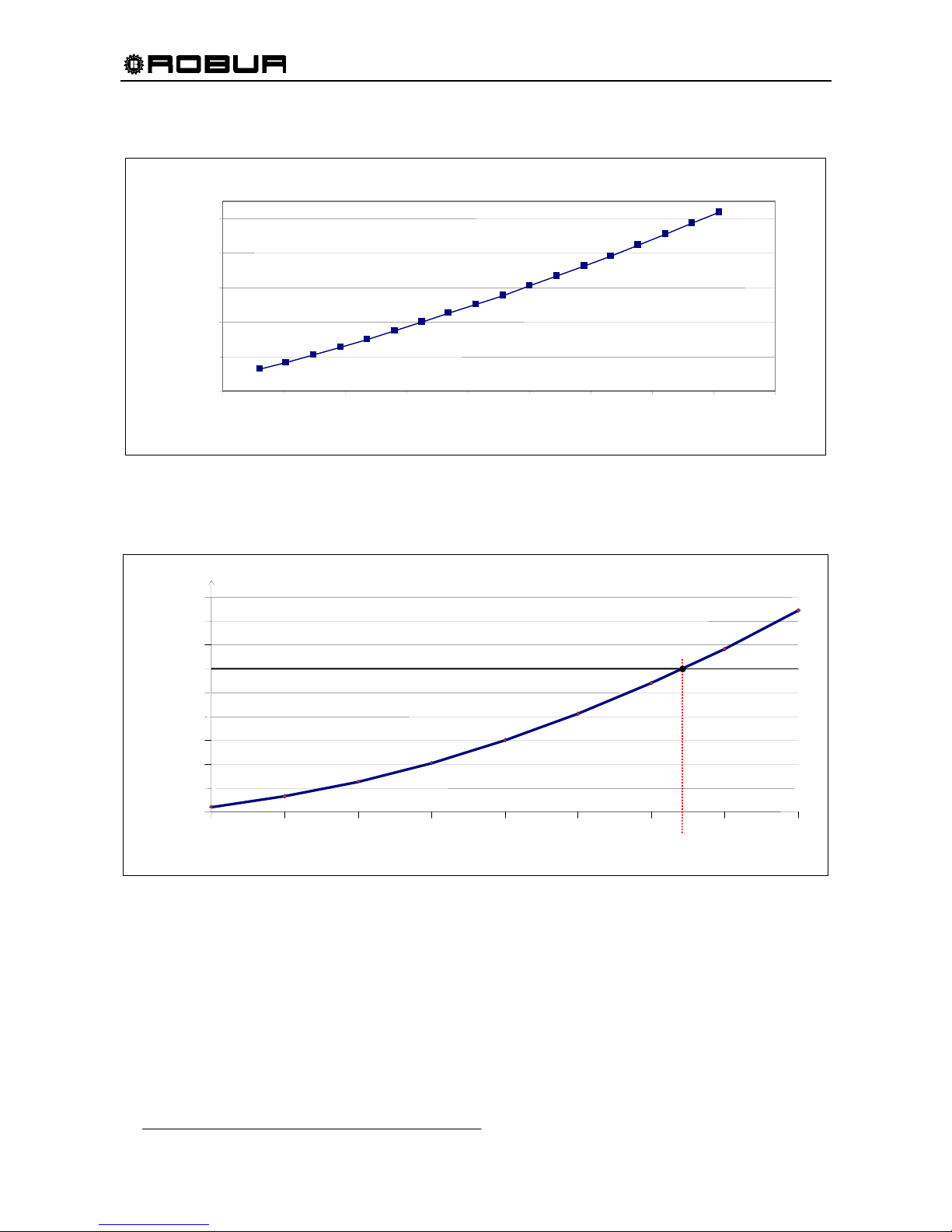
UNIT INTERNAL PRESSURE DROP OPERATION FOR AIR CONDITIONING ONLY (NO RECOVERY)
Graph 3- UNIT PRESSURE DROP AS A FUNCTION OF WATER FLOW, OUTLET WATER TEMPERATURE 44.6 °F
ACF60-00 HR
HEAT RECOVERY UNIT INTERNAL PRESSURE DROP
Graph 4 - ACF60-00 HR: Heat recovery unit pressure drop
2.00
4.00
6.00
8.00
10.00
12.00
6.00 7.00 8.00 9.00 10.00 11.00 12.00 13.00 14.00 15.00
PRESSURE DROP (feet of head)
WATER FLOW (GPM)
ACF60-00
HR
PRESSURE DROP [feet of head]
2.2 3.3 4.4 5.5 6.6 7.7 8.8 9.9 11.0
0.00
0.67
1.34
2.01
2.68
3.35
4.02
4.69
5.36
6.03
9.46
RECOVERY UNIT WATER FLOW [GPM]
A
CF-HR (operation with heat recovery unit, hot water return 20°C)
HEAT RECOVERY UNIT PRESSURE DROP
ACF-HR (operation for AIR CONDITIONING ONLY (no recovery)
Page 29
Installation, Start-Up, Adjustment and Maintenance Manual
27
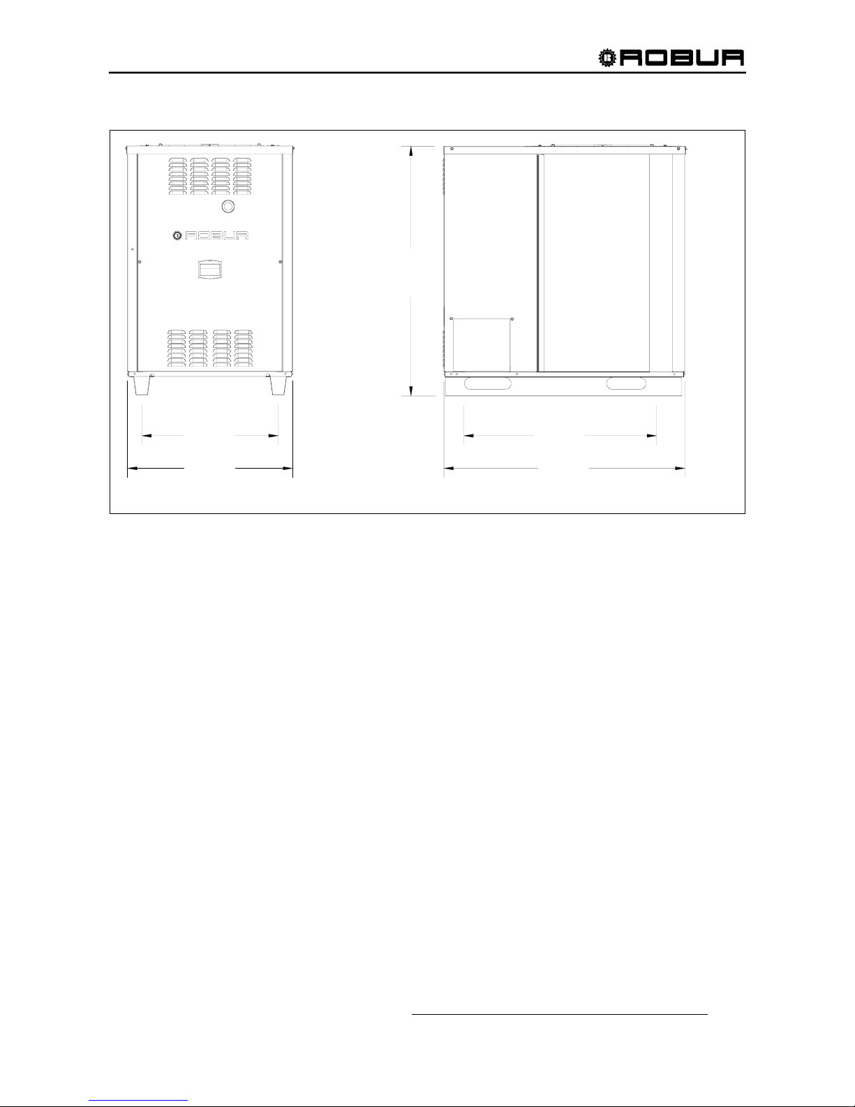
2.4 DIMENSIONS
Figure 3 - ACF60-00, HT, TK, LB, HR DIMENSIONS.
FRONT VIEW
850
975
1.230
700
1.280
27-9/
16
”
33-1/
2
”
38-3/8”
48-1/2”
50-
3
/
4
”
RIGHT SIDE VIEW
Service
Panel
Page 30
Installation, Start-Up, Adjustment and Maintenance Manual
28
3. INSTALLATION
3.1 GENERAL RULES
Only qualified technicians, in compliance with the manufacturer’s instructions, should carry out the
installation and maintenance of the ACF60-00 unit. The installation of the appliance must conform to the
requirements of the authority having jurisdiction or in the absence of such requirements, to the latest edition
of the National Fuel Gas Code, ANSI Z223.1. If the unit is installed in Canada, the installation must conform
to the Canadian Gas Association Standard CAN1 B149.1 and .2.
All wiring should be installed in accordance with the latest edition of the National Electrical Codes,
ANSI/NFPA No. 70, CSA Standard C22.1 when installed in Canada, and with any local codes.
The manufacturer cannot be held responsible for any damages to persons, animals or goods due to
improper, erroneous or irrational installation of these appliances.
To ensure that a correct installation and maximum unit performances are obtained, the following rules have
to be followed:
- Unpack the unit carefully, checking that it has not suffered damage during transport. Each unit is factory
tested before shipping, if damage is found report this immediately to the haulage contractor.
- Each unit must be installed outdoors in an area of free natural air circulation and does not require
particular weather protection.
In no case must the unit be installed in a room.
- No overhead obstructions should block the outlet of air from the unit top.
- The unit should not be installed so that the fan discharge is in close proximity to the fresh air
intakes of a building or in such a manner that hot or contaminated air from flues, dryer vents,
chimney, etc., could be drawn into the unit by the condenser fan.
- The front and rear sides of the unit must have a minimum clearance of 31-
1
/2” inches and 24 inches,
respectively, (for safety, maintenance and servicing) from any combustible surface, walls or
other stationary constructions. The left and right sides require a minimum distance of 18 inches
for proper airflow toward the condenser.
- Be sure that gas supply provided from the gas main meets the manufacturer’s specifications. Inlet gas
pressure to the unit must not exceed 14.0" W.C. on natural gas or propane gas. The minimum Inlet gas
pressure at the unit is 5.0" W.C. on natural gas and 11.0" W.C. on propane gas.
The electrical safety of the unit is obtained only when it is correctly connected to an efficient grounding
system, which meets existing applicable safety standards. Never use gas supply piping to ground the
appliances. The ground wire should be longer than power supply wires for safety reasons. If the power
supply wires are accidentally stretched, the ground wire will be the last to break. By following this rule, good
ground continuity will be assured.
WARNING
Page 31
Installation, Start-Up, Adjustment and Maintenance Manual
29
3.2 INSTALLATION OF THE UNIT
HANDLING OF THE UNIT ON SITE
When arriving at the installation site, visually inspect the unit for any signs of damage to the package, which
may indicate possible unit damage.
Once on site, the units must remain in the factory packaging and only be unpacked at the moment before
installation.
Before locating and unpacking the unit, make a hole in the package to check for ammonia odor. If ammonia
odor is present, contact the factory.
LOCATION
The chillers must be installed outdoors in an area of free natural air circulation.
The installation inside a room or a building is not allowed.
There must be a minimum clearance of 4 feet horizontally from electric meters, gas meters, regulators, and
relief equipment and in no case located above or below these items unless a 4 feet horizontal distance is
maintained.
The unit can be installed at ground level, on a platform or on the roof (if it can withstand the weight).
The noise generated by the condenser fan during unit operation is not excessive. However, avoid locating
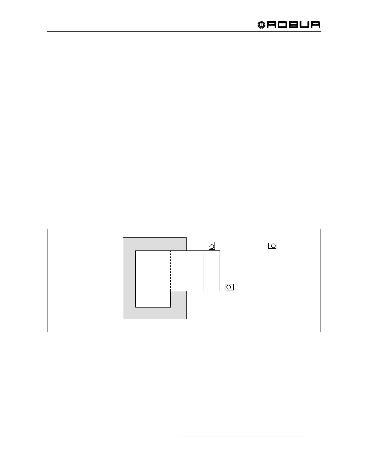
the unit in an area adjacent to bedrooms or neighboring buildings (see Figure 4).
Also, avoid installing the unit in building corners, where air turbulence can take place or the unit noise
(reverberation) can be amplified.
Figure 4 - LOCATION OF THE UNIT
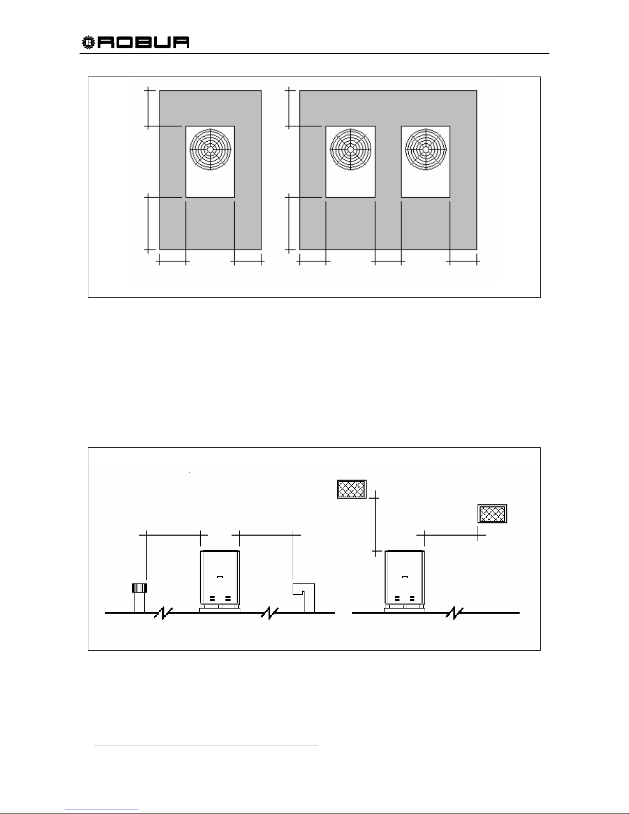
CLEARANCES
A free space is to be provided around the unit to allow for proper unit operation and for servicing. The
minimum clearance from walls, obstructions and other units should be as follows (see Figure 5):
• right / left side: 18 inches
• rear side: 24 inches
• front side: 31-
1
/2 inches
BEDROOMS
LIVING
ROOM
GARAGE
GOOD
BETTER
IDEAL
AVOID
INSTALLATION IN
THIS AREA
Page 32
Installation, Start-Up, Adjustment and Maintenance Manual
30
Figure 5 – CLEARANCES FOR CORRECT INSTALLATION OF THE UNIT
There MUST NOT be any obstructions or structural overhangs (roof edges, balconies) over the top of the
unit. The re-circulation of the air discharged from the condenser results in a poor unit performance.
When the unit is installed in close proximity to buildings, keep the unit away from the roof edge drip line. In
no case should the unit be placed within 6 feet of any external air intakes of the building. For installations on
balconies or roofs, the unit should not be located within 8 feet from chimney flues, outlets and other such
vents. It is important that the unit is located so that hot or contaminated air IS NOT drawn into the air intakes
of the unit (see Figure 6).
Figure 6 – CLEARANCES FROM VENT OUTLETS, CHIMNEY FLUES AND AIR INTAKE OPENINGS
ROOF / TERRACE INSTALLATION GROUND INSTALLATION
6 FT. MIN
6 FT. MIN.
8 FT. MIN.8 FT. MIN.
18” 18” 18” 18” 18”
31
-
1/2
”
24
”
31
-
1/2
”
24
”
SINGLE UNIT MULTIPLE UNITS
Page 33
Installation, Start-Up, Adjustment and Maintenance Manual
31
GROUND INSTALLATION
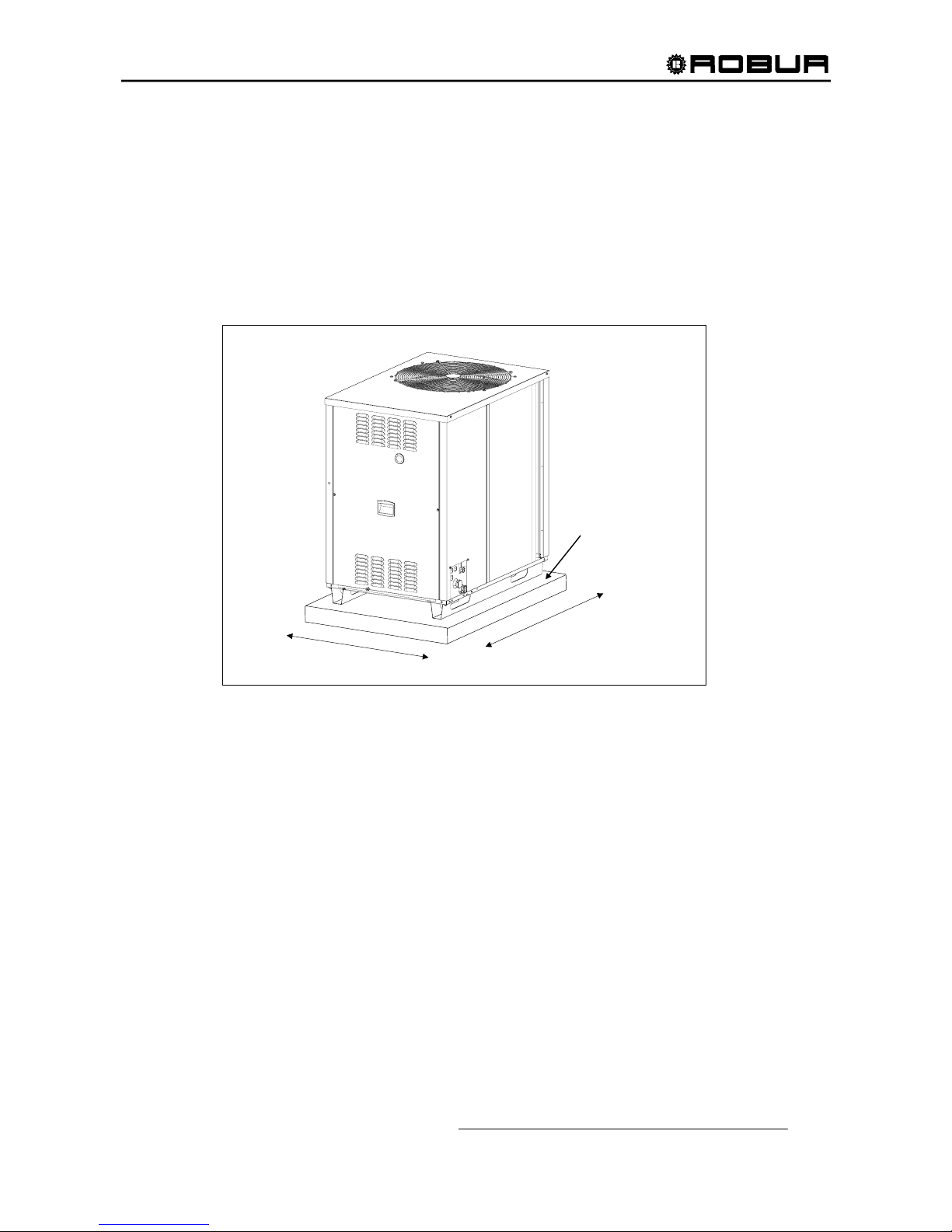
Ground level units should be supported on a LEVEL concrete pad with a minimum thickness of 4" and
slightly larger than the unit base (see Figure 7 for typical slab dimensions). Local soil conditions will actually
dictate the slab thickness required to prevent shifting.
Do not allow the concrete slab touch the foundation of a structure. Unit operational noises can be transmitted
inside the structure if they are connected.
Ground level installations should use vibration-damping base supports, available from the factory. Another
option is to use 4" thick concrete blocks positioned under the unit, instead of the factory base supports.
Figure 7 – DIMENSIONS OF THE UNIT BED
ROOF / TERRACE INSTALLATION
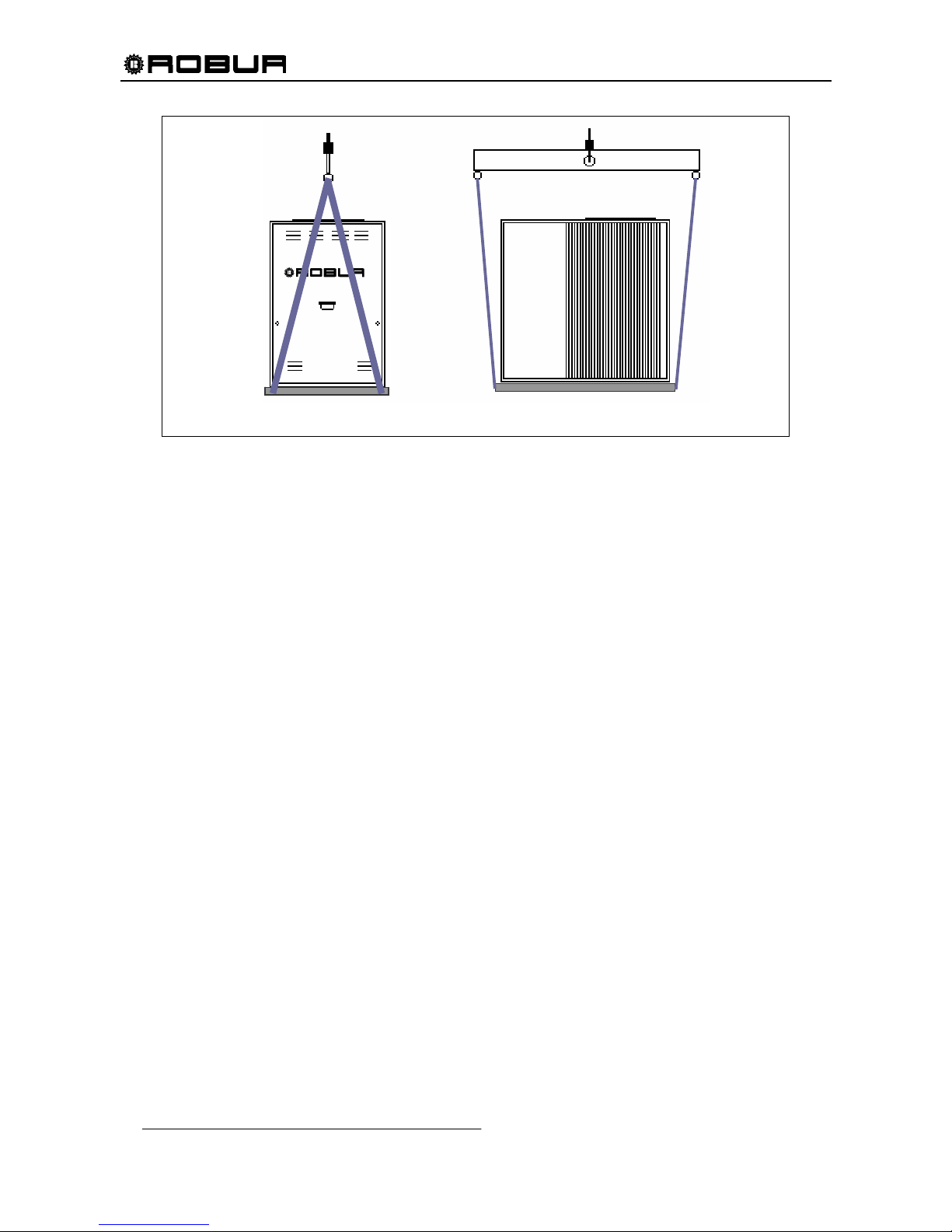
If the unit must be lifted by a hoist for installation, leave it on the crate base. Attach hoist lines to the crate
base and use spreader bars to prevent the hoist lines from damaging UNIT cabinet panels.
4” CONCRETE
SLAB
35” TYPICAL
50” TYPICAL
Page 34
Installation, Start-Up, Adjustment and Maintenance Manual
32
Figure 8 – HANDLING OF THE ACF60-00 UNIT
Although approved for installation on a combustible base, the unit must not be installed directly on the roof
surface. Use base supports for the installation (see Figure 7).
Both the unit and the supporting base weight should be sufficiently supported by the roof joists.
Provide for a gangway all around the unit for maintenance purposes.
Installation on roofs directly above sleeping quarters should be avoided if possible. If not possible, special
consideration must be given to the transmission characteristics of the building structure. The use of vibration
isolators under the equipment (acoustically insulated bases) and approved flexible connections (vibrationdamping pipe fittings) between the unit and the piping system is recommended.
LEVELING
The unit should be level both front to back and side to side. Place a level on the top of the unit to check for
level. If the unit is not level, metal shims are recommended for use under proper corners to obtain level. If
the shim(s) thickness exceeds 1/2", support shims should be inserted under the center of the unit.
FRONT VIEW SIDE VIEW
Page 35
Installation, Start-Up, Adjustment and Maintenance Manual
33
4. HYDRONIC AND GAS INSTALLATION
4.1 WATER PIPING DESIGN AND INSTALLATION
Piping for the chiller is to be designed and installed as a closed hydronic circuit.
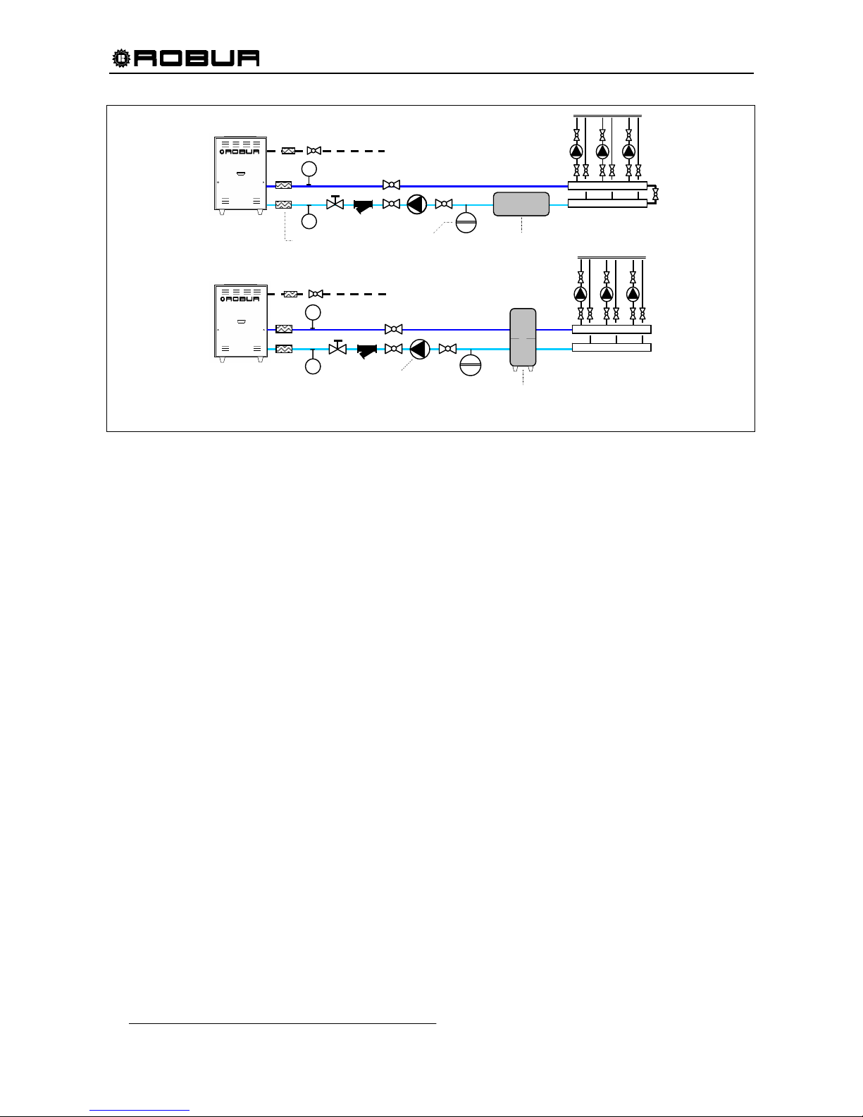
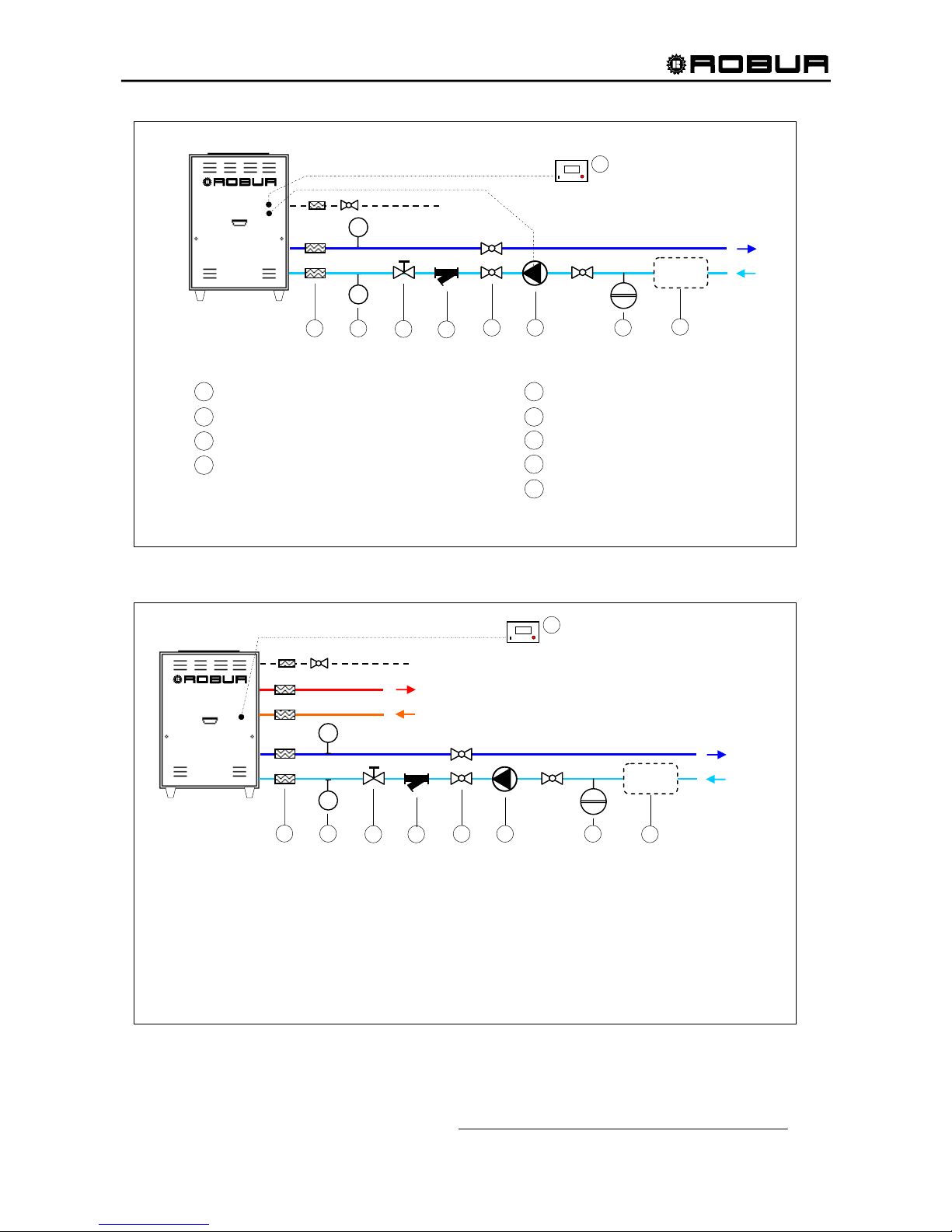
The following items (not supplied) must be installed close to the unit (see Figure 9):
- FLEXIBLE CONNECTIONS to avoid vibration transmission to the chiller water lines.
- MANOMETERS to measure Inlet and Outlet pressure.
- CHILLED WATER FILTER mounted in the water Inlet line to remove debris from the chiller water
lines.
- WATER FLOW RATE VALVE for adjusting proper water flow rate.
- WATER PUMP properly sized for system.
- EXPANSION TANK must be properly sized based on the hydronic system size, maximum thermal
expansion, and maximum water pressure.
- FILL VALVE for filling, draining or flushing the hydronic system.
- AIR BLEED set at the highest point in the hydronic system for removal of air.
To ensure the correct operation of the unit and to avoid the water freezing, add 10% by volume
of mono-ethylene glycol (antifreeze) to the circulation water. Add more mono-ethylene glycol as
needed for the minimum external temperature of the installation zone (see Table 18, page 53).
When using an automatic water charge system, the mono-ethylene glycol percentage must be checked once
a year.
There must be correct chilled water flow when the unit is operating and during the shut down period (600
seconds, between turning the burner off and complete shutdown of the appliance).
Piping (diameters of tubes etc.) must be sized appropriately in order to ensure the correct chilled water flow
necessary for the proper operation of the unit. The water lines should also be sized so the maximum velocity
of the water/mono-ethylene glycol solution in the lines does not exceed 6 feet per second to avoid excessive
noise.
Absorption cooling unit does not require obligatory installation of cold-water storages (because there is no
compressor in the system).
The use of the cold-water storage is anyhow suggested, in order to absorb frequent variations of thermal
load, that reduces the working time of the unit, reduces the energy consumption and consequently saving
money. It is recommended specially when water quantity in the system is lower than 18.5 gallons for each
installed ACF60-00 unit.
WARNING
Page 36
Installation, Start-Up, Adjustment and Maintenance Manual
34
Figure 9 – EXAMPLE OF HYDRONIC SYSTEMS WITH SINGLE COLD-WATER STORAGE (TOP) and PRIMARY-
SECONDARY WATER STORAGE (BOTTOM)
When rigid pipes are used, it is recommended to use flexible connections between the unit and piping to
avoid vibration transmission.
All piping must be properly insulated according to federal and local codes to avoid thermal losses and
condensate on the water lines. All seams and joints should be carefully made so as to be air and watertight.
For size of water connections on the unit, refer to TECHNICAL DATA sheet (2.3)
Connections at the coil or heat exchanger must be performed in accordance with the recommendations of
the coil or heat exchanger manufacturer. For best performance, the supply-chilled water line must attach to
the side of the coil or heat exchanger nearest the exit of the leaving cooled medium.
If the heat exchanger is an air coil, the air coil must be installed downstream from the furnace to avoid
condensation in the furnace. Additionally if the heat exchanger is an air coil, a “P” trap must be provided to
drain condensate. The height of the “P” trap must be sufficient to ensure drainage of condensate. Any
horizontal run of the condensate drain line must slope ¼” for each running foot and not be smaller than ¾”
I.P.S. to assure the condensate will drain by gravity. The condensate drain line must be insulated and ran to
a suitable drain.
®
P
P
®
P
P
GAS
GAS
WATER OUTLET
WATER OUTLET
FLEXIBLE JOINTS
EXPANSION
VESSEL
COLD-WATER STORAGE
PRIMARY AND
SECONDARY COLD-
WATER STORAGE
WATER CIRCULATION
PUMP
Page 37
Installation, Start-Up, Adjustment and Maintenance Manual
35
Figure 10 – WATER PIPING DIAGRAM FOR A SINGLE ACF UNIT
Figure 11 – WATER PIPING DIAGRAM FOR A SINGLE ACF-HR UNIT
®
A
CF60-00 HR
1
5 6
7
3
4
P
P
2
8
REQUIRES USE OF ANTIFREEZE OR EMPTYING OF APPLIANCE IN WINTERTIME
DELIVERY
IF USED
RETURN
9
DDC
GAS
RECOVERED HOT WATER DELIVERY
CHILLED WATER
RECOVERED HOT WATER RETURN
(available as an accessory)
KEY
1 FLEXIBLE CONNECTORS 6 PUMP
2 PRESSURE GAUGES 7 EXPANSION VESSEL
3 FLOW CONTROL VALVE 8 ACCUMULATION TANK
4 WATER FILTER 9 DIRECT DIGITAL CONTROLLER
5 SHUT-OFF VALVE
LEGEND:
FLEXIBLE CONNECTIONS ON / OFF VALVE
MANOMETERS WATER PUMP
WATER FILTER EXPANSION TANK
WATER FLOW RATE VALVE COLD WATER STORAGE
DDC (OPTIONAL)
1
2
3
4
6
7
5
NOTE: ANTIFREEZE GLYCOL MUST BE ADDED INTO THE CHILLED WATER OR EMPTY OUT THE UNIT FROM WATER DURING WINTER:
SEE Table 18, page 40
8
56
7
P
P
2
8
®
9
DDC
UNIT ACF 60-00
GAS
WATER OUT
1
3
4
9
Page 38
Installation, Start-Up, Adjustment and Maintenance Manual
36
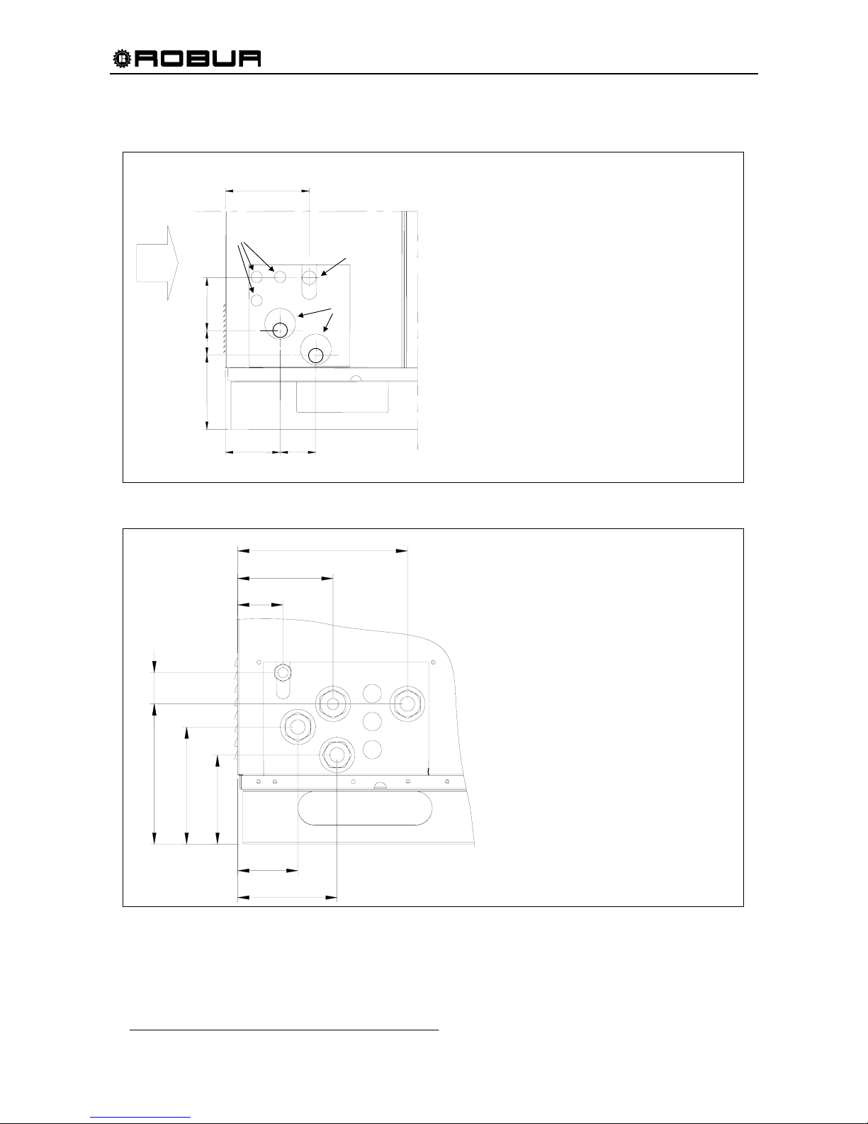
The connections for water and gas piping are located at the service plate on the right-side of the chiller
(see Figure 3).
Figure 12 – ACF 60-00, TK, HT, LB - SERVICE PLATE DIMENSIONS
Figure 13 – ACF 60-00 HR - SERVICE PLATE DIMENSIONS
79
200
150
250
108
181
170
303
59
CONNECTIONS PANEL ACF-HR
KEY
G - GAS SUPPLY ∅ ½” FPT
Chiller – CHILLED WATER
D - WATER DELIVERY
TO APPLIANCE ∅ 1” 1/4 FPT
C - WATER RETURN
TO UNIT ∅ 1” 1/4 FPT
Recovery unit – HOT WATER
A - WATER DELIVERY
TO APPLIANCE ∅ 1” 1/4 FPT
B - WATER RETURN
TO UNIT ∅ 1” 1/4 FPT
D
B
C
G
A
11-15/
16
”
6-11/
16
”
3-1/8”
7-1/
8
”
4-1/4”
5-
7
/
8
”
7-
7
/
8
”
9-
7
/
8
”
2-
5
/
16
”
CONNECTION PANEL ACF 60-00, TK, HT, LB
G GAS CONNECTIONS ∅ ½” FPT
W WATER CONNECTIONS ∅ 1” 1/4 FPT
E ELECTRICAL KNOCKOUTS ∅ 7/8
5 – 7/8” 2” 4 - 1/8”
4 – ¼” 2– 7/8”
6 - ½
”
G
W
E
UNIT
FRONT
Page 39
Installation, Start-Up, Adjustment and Maintenance Manual
37
4.2 GAS SUPPLY PIPING
All gas piping must conform to the latest edition of National Fuel Gas Code ANSI Z223.1 and all local gas
piping codes. In Canada, the gas piping must conform to the CGA Standard CAN1 B149.1 and .2,
"Installation Code for Gas Burning Appliances & Equipment" and local codes. Your gas utility must be
contacted regarding local requirements, type and size of gas lines. Safe lighting and other performance
criteria were met with the gas manifold and control assembly provided on the chiller, when it underwent the
tests specified in the standards shown on the rating plate.
For Natural Gas the minimum Inlet gas pressure to the chiller is 5" W.C. and the maximum is 14” W.C. For
Propane Gas the minimum Inlet gas pressure to the chiller is 11" W.C. and the maximum is 14" W.C.
For size of gas connection to the unit, see Figure
12.
Gas supply pressures higher than those stated above could damage the gas valve, resulting in a fire
hazard.
Vertical gas piping must be trapped and a means provided to drain condensate that may accumulate in the
piping during the cold season. Insulation may also be necessary for the gas piping to prevent excessive
accumulations of condensate.
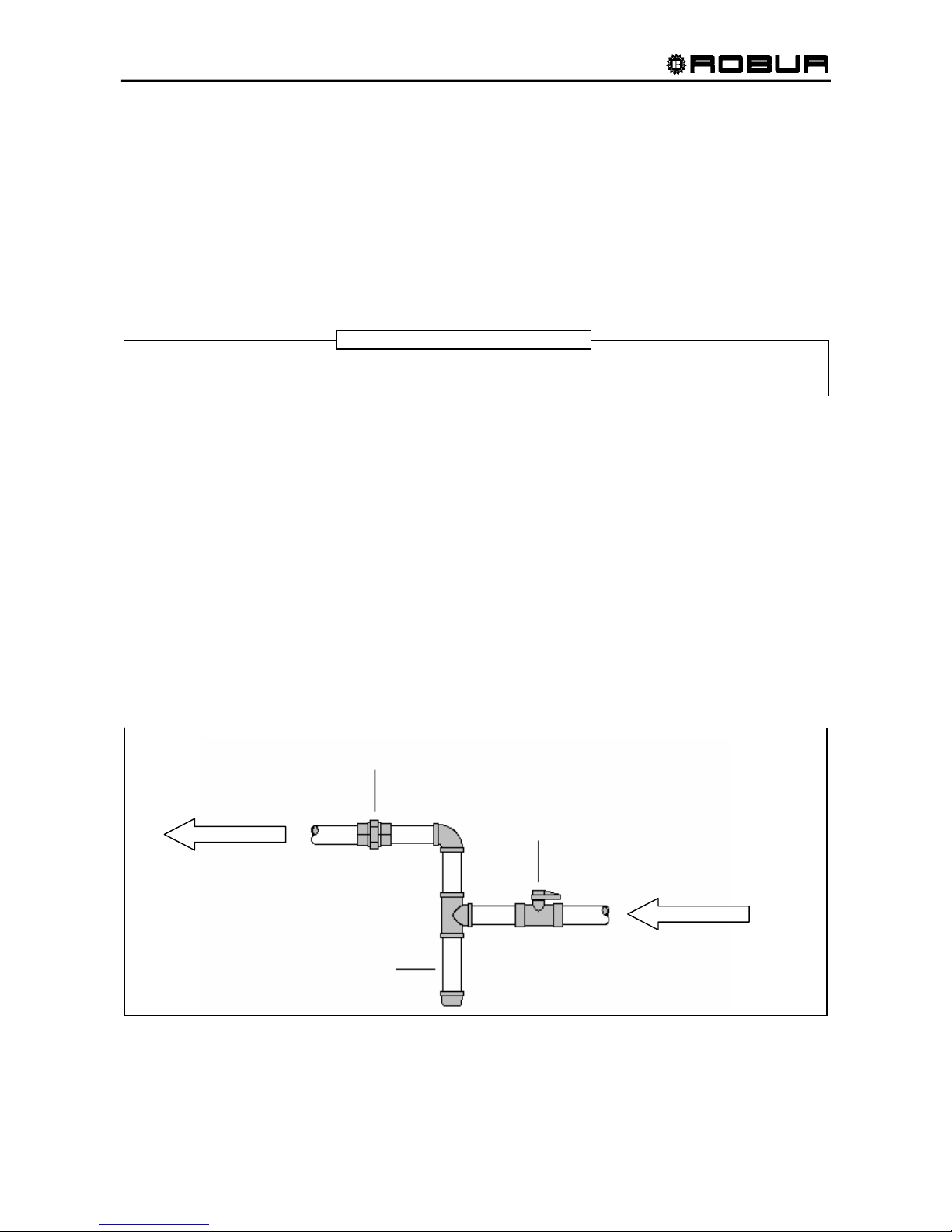
An approved union should be installed in the gas line near the unit and down stream of any external shut-off
valve that may be required by local codes.
Be sure to use materials resistant to the LPG corrosive action when making pipe connections.
Use an approved sealing compound resistant to propane gas on all male pipe threads.
The chiller and its gas connections must be leaked tested before placing the chiller in operation.
The chiller and its individual shut-off valve must be disconnected from the gas supply piping system during
any pressure testing of the gas piping system at test pressures in excess of 1/2 PSIg.
The chiller must be isolated from the gas supply piping system by closing its individual shut-off valve during
any pressure testing of the gas piping system at test pressures equal to or less than 1/2 PSIg.
Figure 14 – TYPICAL GAS CONNECTION
APPROVED GAS
SHUT-OFF VALVE
TO UNIT
FROM GAS
SUPPLY
WARNING
Page 40
Installation, Start-Up, Adjustment and Maintenance Manual
38
5. ELECTRICAL CONNECTION
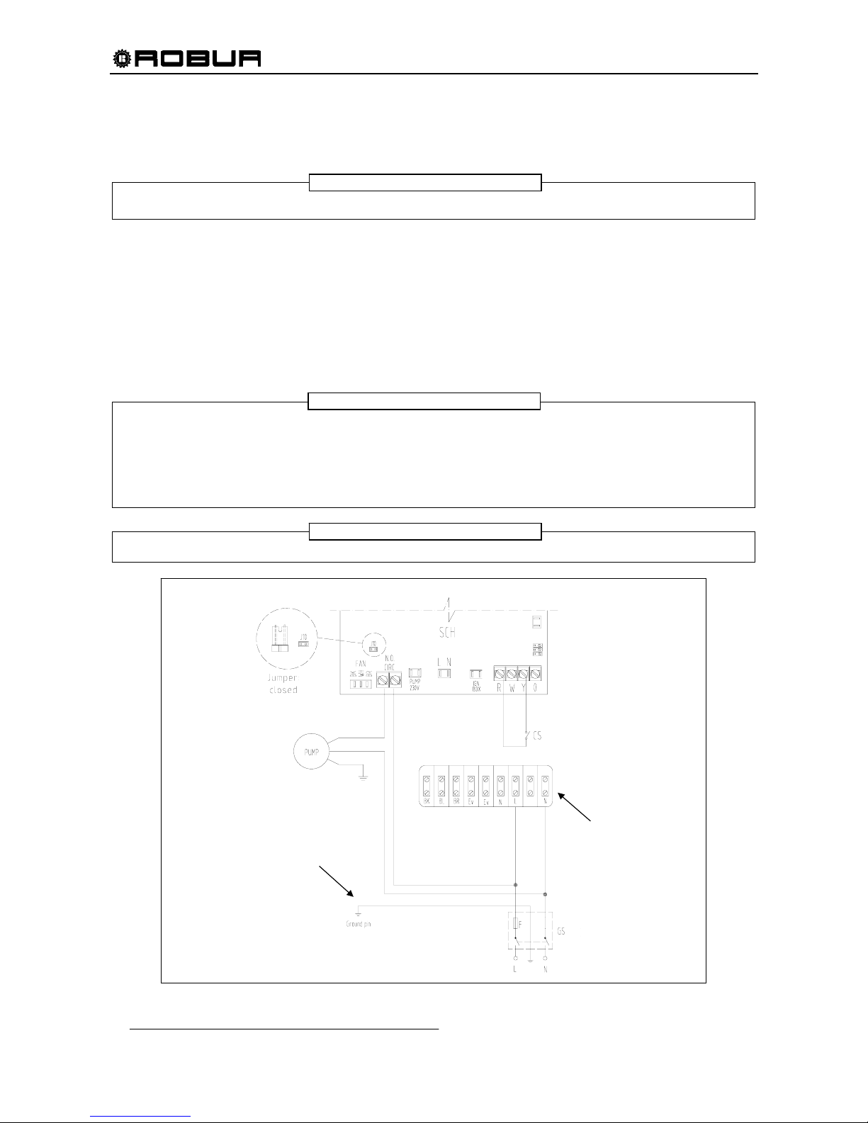
IN THE FOLLOWING SECTION PLEASE REFER TO "L" AS "L1" AND TO "N" AS "L2".
5.1 POWER SUPPLY AND PUMP WIRING FOR A SINGLE ACF60-00 UNIT
All wiring should be installed in accordance with the latest edition of the National Electrical Codes,
ANSI/NFPA No. 70, CSA Standard C22.1 when installed in Canada, and with any local codes.
The UNIT electrical system is wired for single-phase, 208-230 volt and 60Hz operation. The electrical control
box includes a 208 – 230 - 24 volt transformer to supply low voltage to the control system. The high voltage
line connections to be made at the time of installation consists of connecting 208-230 volt, 60 Hz to the high
voltage terminal board of the control panel. A fused disconnect switch should be installed in the 208-230 volt
supply line within sight of and not over 50 feet from the unit.
- An error in wiring installation could cause problems during the UNIT operation and could damage the
electrical components of the appliance.
- The unit must be electrically grounded in accordance with national requirements.
- The power supply line must not be used to turn the unit “ON” or “OFF”. The dedicated control switch in
the R-Y line is for this purpose.
- Disconnect the power supply lines only when assured that unit is completely shut off.
DO NOT OPERATE the unit unless the chilled water system is filled with water and antifreeze.
(
GENERAL SWITCH)
(
CONSENT SWITCH)
USE A 15 AMP TIME
LAG FUSE ON L WIRE.
L, N WIRING TO THE
TERMINAL BOARD MUST
BE DONE RESPECTING
THE CORRECT POLARITY
GROUND CABLE HAS TO BE
CONNECTED BY A SUITABLE EYELET
TO THE GROUND PIN INTO THE
ELECTRICAL BOX, AND FIXED TO IT
BY THE PROPER PRESET NUT.
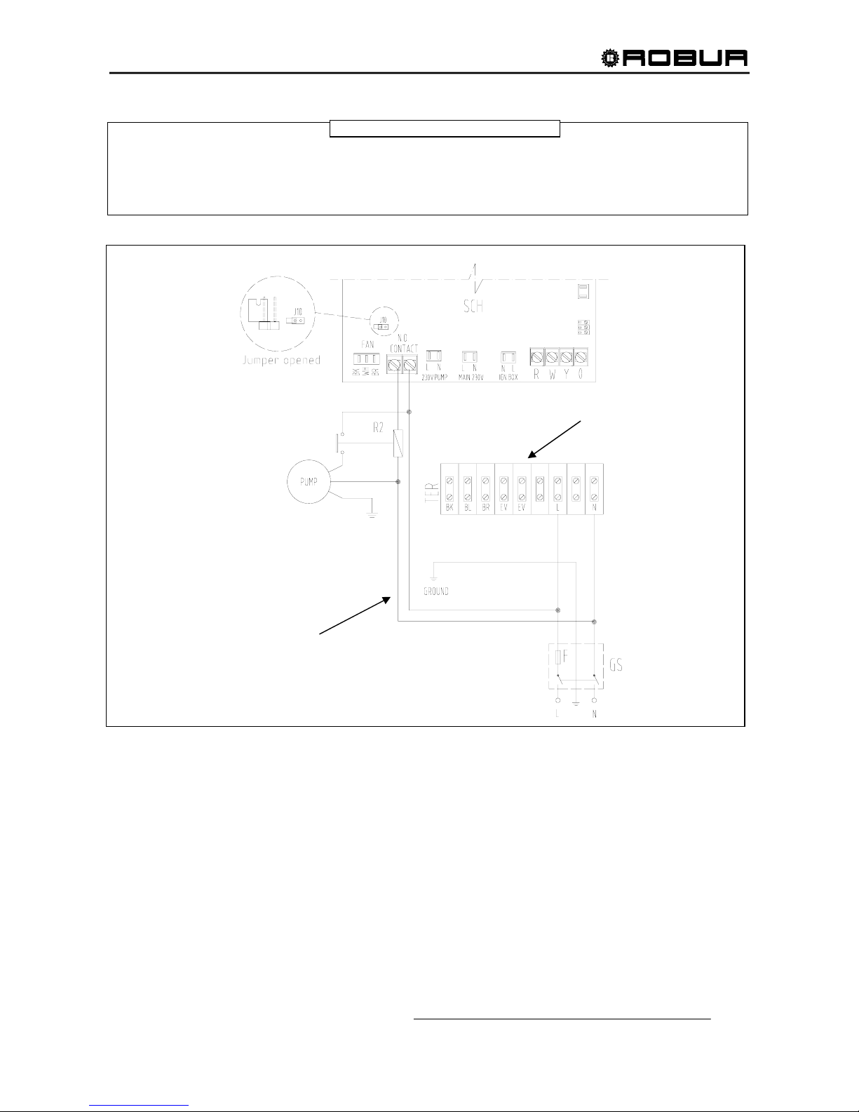
Figure 15 – WIRING FOR A SINGLE ACF60-00 UNIT WITH PUMP ABSORBED CURRENT LESS THAN 4 AMP.
NOTE
WARNING
WARNING
Page 41
Installation, Start-Up, Adjustment and Maintenance Manual
39
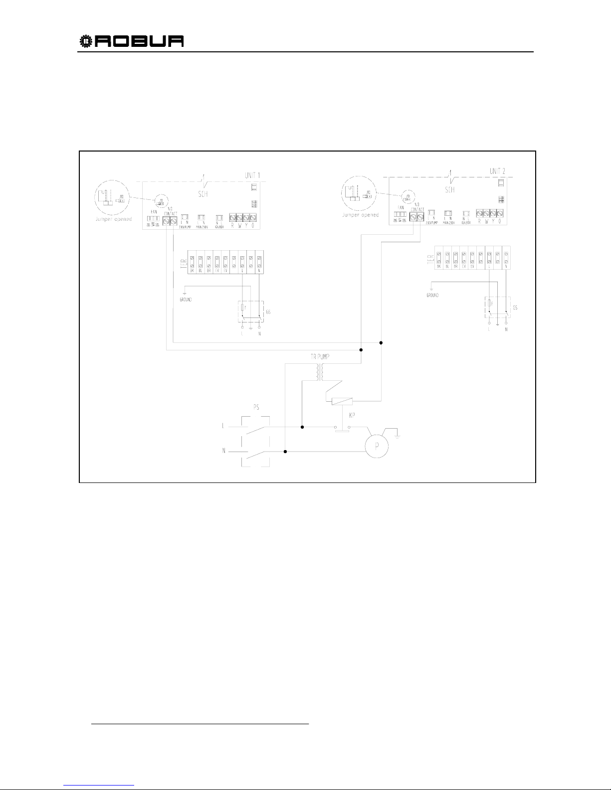
Figure 16 – WIRING FOR A SINGLE ACF60-00 UNIT WITH PUMP ABSORBED CURRENT MORE THAN 4 AMP
If power for the water pump is taken from the high voltage terminal block located in the electrical control
box, as shown in Figure 15, the minimum circuit ampacity for the unit must be increased above that listed in
the TECHNICAL DATA sheet in SECTION 2 to accommodate the additional current draw of the water
pump installed. The maximum current carrying capacity of the N.O. Contact is 4A. If the current is
above 4A, use an additional relay controlled by N.O. Contact on the S61 board.
WARNING
(
GENERAL SWITCH
)
GROUND CABLE HAS TO BE
CONNECTED BY A SUITABLE EYELET
TO THE GROUND PIN INTO THE
ELECTRICAL BOX, AND FIXED TO IT
BY THE PROPER PRESET NUT.
L, N WIRING TO THE
TERMINAL BOARD MUST
BE DONE RESPECTING
THE CORRECT POLARITY
USE A 15 AMP TIME
LAG FUSE ON L WIRE.
Page 42
Installation, Start-Up, Adjustment and Maintenance Manual
40
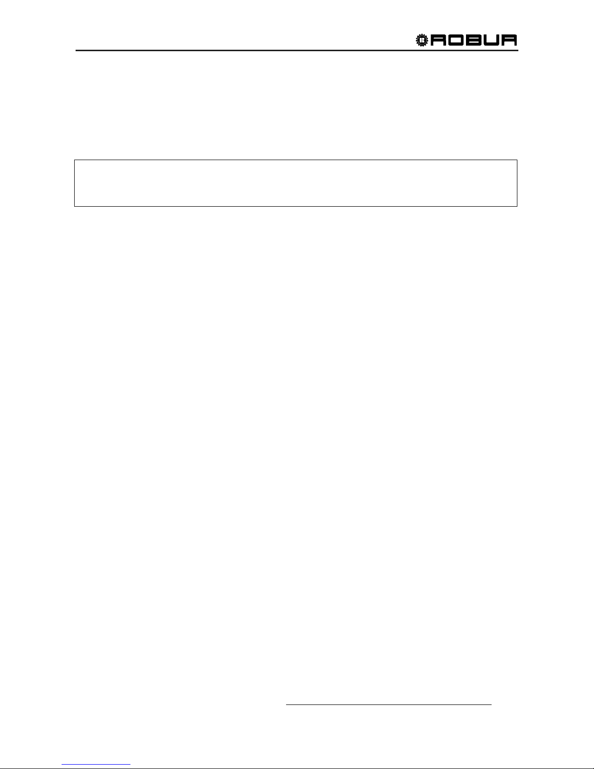
5.2 POWER SUPPLY AND PUMP WIRING FOR 2 OR MORE ACF60-00 UNITS
The figure shows typical wiring for 2 or more ACF60-00 units. The transformer is required to feed N.O.
contacts with low voltage current; this is done for safety reasons: when doing maintenance and a unit is shut
off, these contracts could still remain fed. In this case, no matter if pump current absorption is more or less
than 4 amp.
Figure 17 - WIRING FOR 2 ACF60-00 UNITS WITH LOW VOLTAGE TRANSFORMER
Page 43
Installation, Start-Up, Adjustment and Maintenance Manual
41
5.3 CONTROL SWITCH WIRING AND THERMOSTAT LOCATION
CONSENT SWITCH WIRING
If DDC is not used, a consent switch that provides an ON/OFF function is to be connected to the R and Y on
the S61 board. This wiring will carry 24-volt current and it is recommended to use a cable with the correct
number of color-coded 18 AWG wires.
An isolation relay MUST be used to separate the chiller’s transformer from any additional
equipment having a transformer or damage to the S61 board will occur. Isolation relays must have
a 24-volt AC coil, which does not present more than 0.25 amp load to the control circuit.
THERMOSTAT LOCATION
If the control switch is a thermostat, the thermostat should be located on an inside wall about 54 inches
above the floor. It should be located so that it will no be affected by any of the following items:
- Discharge air from a supply grille
- Drafts
- Direct sunlight through a window or glass door
- Electrical Appliances such as television, radio or lamps.
The thermostat should be located so that it senses the average temperature of the conditioned space. The
thermostat should be mounted according to the manufacturer’s instructions (packaged with the thermostat).
THERMOSTATS USING A MERCURY BULB SWITCH MUST BE LEVEL. If the thermostat has a built-in
heating anticipator, this must be set as required by the heating unit load.
Page 44
Installation, Start-Up, Adjustment and Maintenance Manual
42
5.4 ACF60-00 WIRING
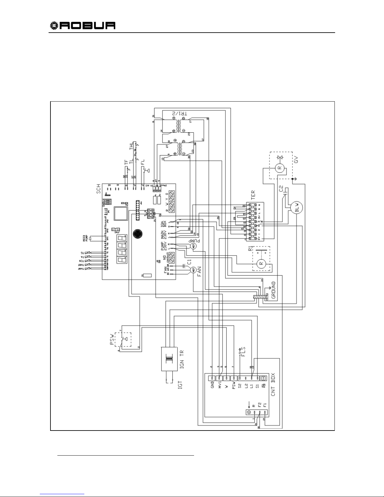
If any of the original wire as supplied w ith the unit mus t be replaced, it m ust be replaced w ith thermoplastic
221°F wire, except groun d, hig h temperature and pressure switch wires 392°F or equivalent.
Igniter and flame sensor wire have to be replaced with Robur spare parts. See, SPARE PART S, page 60.
Label all wires prior to disconnection when servicing the controls. W iring errors can cause improper
and dangerous operation.
In Figure 20, below, Thermostat THL (Hot water outlet thermostat) is placed only on ACF60-00 HR.
Figure 18 – WIRING DIAGRAM FOR ACF60-00
Page 45
Installation, Start-Up, Adjustment and Maintenance Manual
43
5.5 DDC CONNECTION
Connection with ACF60-00 UNIT
For the connection of DDC (available as accessory) with ACF60-00 units, consult the instructions, figures and diagrams
only contained in this subparagraph. For further details and/or information refer to the specific “DDC installation,
programming and use manual”.
To well manage one or more units connected to the same hydronic system, it is important to use the DDC,
available as accessory. In such a case, it is necessary to:
- Connect the DDC to the power supply (see “DDC: Electric supply wire connection”)
- Use a CAN-BUS wire to connect the units and the DDC (see “Connection of DDC to the unit”)
DDC: Electric supply wire connection
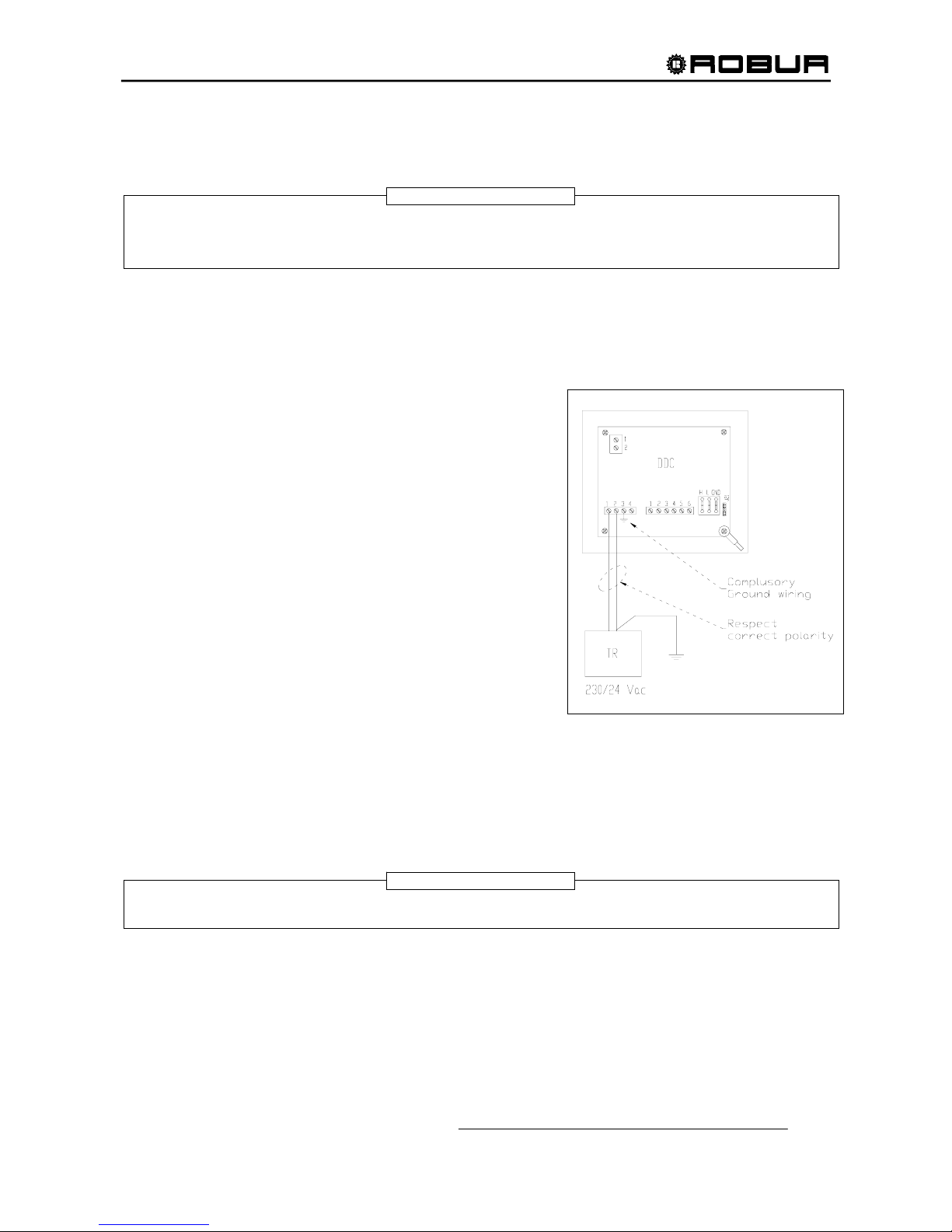
The DDC should be electrically supplied through a safety
transformer 230 /24 V.a.c. – 60 Hz. With minimum power equal
to 20 VA.
Use an electric supply wire (min. 2 x 18 AWG) and the 4
terminals connector of the DDC (placed at bottom left, back
side) to make the connection as in Figure 19, respecting the
following polarity:
- terminal 1 = 24 V;
- terminal 2 = 0 V;
- terminal 3 = ground
Warning: in all cases terminal 3 of the DDC terminals
connector should be connected to one safety ground (≤ 0,1Ω).
The DDC is also equipped with a plug battery which, in case of
black out, stores in its memory the programmed values; the
plug battery lasts approximately 7 years, then it should be
changed by authorized Service Engineer (TAC).
Figure 19– ELECTRICAL SUPPLY WIRE
CONNECTION
Connection of DDC to the unit
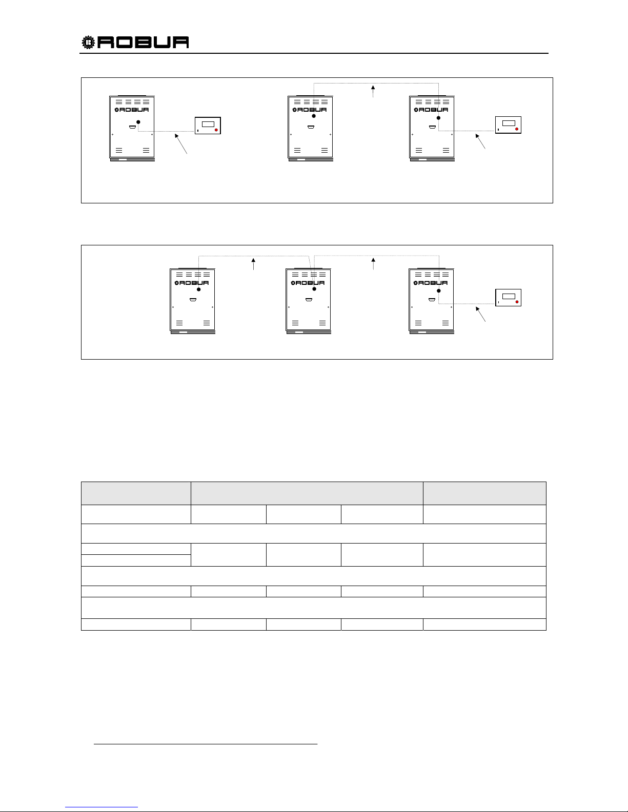
The connection between DDC and the unit (or more units) is made through a CAN-BUS wire, in a way to
create a parameters communication network, characterized by one series of “n” nodes (see Figure 20 and
Figure 21, pag. 44). The parameters communication network can connect max 3 DDC.
Every single object (ACF60-00 unit or DDC) at its connection to the communication network is intended to be a node. Every network
is composed by 2 terminal nodes and of a certain number of intermediate nodes.
NOTE
WARNING
Page 46
Installation, Start-Up, Adjustment and Maintenance Manual
44
® ® ®
® ® ®
Figure 20 – EXAMPLE CONNECTION OF DDC TO SINGLE ACF60-00 UNIT (2 nodes network) AND TO N.2
ACF60-00 UNITS CONNECTED ON THE SAME HYDRONIC SYSTEM (3 nodes network).
Figure 21 – EXAMPLE CONNECTION OF DDC TO N.3 ACF60-00 UNITS CONNECTED ON THE SAME HYDRONIC
SYSTEM (4 nodes network).
CAN-BUS wire connection
If the network connection is max 650 ft cable long and has max 6 nodes (e.g.: 5 ACF60-00 + 1 DDC) a
simple shielded wire 3 x 18 AWG is required.
For major lengths, the CAN-BUS wire should be compatible with Standards Honeywell SDS.
The next Table shows some examples of these wires, according to the total length of the wire itself:
CABLE TYPE AND
MODEL
COLOR AND SIGNAL
MAX DISTANCE COVERED
ft
ROBUR NETBUS
BLACK = H WHITE = L BROWN = GND 1475
Honeywell SDS 1620
BELDEN 3086A
TURCK type 530
BLACK = H WHITE = L BROWN = GND 1475
DeviceNet Mid Cable
TURCK type 5711 BLUE = H WHITE = L BLACK = GND 1475
Honeywell SDS 2022
TURCK type 531 BLACK = H WHITE = L BROWN = GND 656
Table 17 – EXAMPLE OF TYPES OF WIRES USED FOR CAN-BUS
NOTE: “GND” is the common signal wire, and NOT a ground connection.
Take the CAN-BUS wire of suitable length for the connection between DDC and the unit and, for every
network or CAN-BUS wire segments (from a node to another) cut sheath of the wire from both terminal for
about 3” length and connect them to the proper nodes, on the electronic control board (S61) or on DDC.
4
C
AYF 60-119
ACF60-00
2
CAN-BUS wire
(see SPARE PARTS)
1
DDC
A
2
1st segment of
CAN-BUS wire
(SEE SPARE PARTS)
1
DDC
A
2nd segment of
CAN-BUS wire
(SEE SPARE PARTS)
3
B
ACF60-00
ACF60-00
AYF 60-119
2
1° segment of
CAN-BUS wire
(SEE SPARE PARTS)
1
DDC
A
2° segment of
CAN-BUS wire
(SEE SPARE
PARTS)
3
B
AYF 60-119
3° segment of
CAN-BUS wire
(SEE SPARE
PARTS)
Page 47
Installation, Start-Up, Adjustment and Maintenance Manual
45
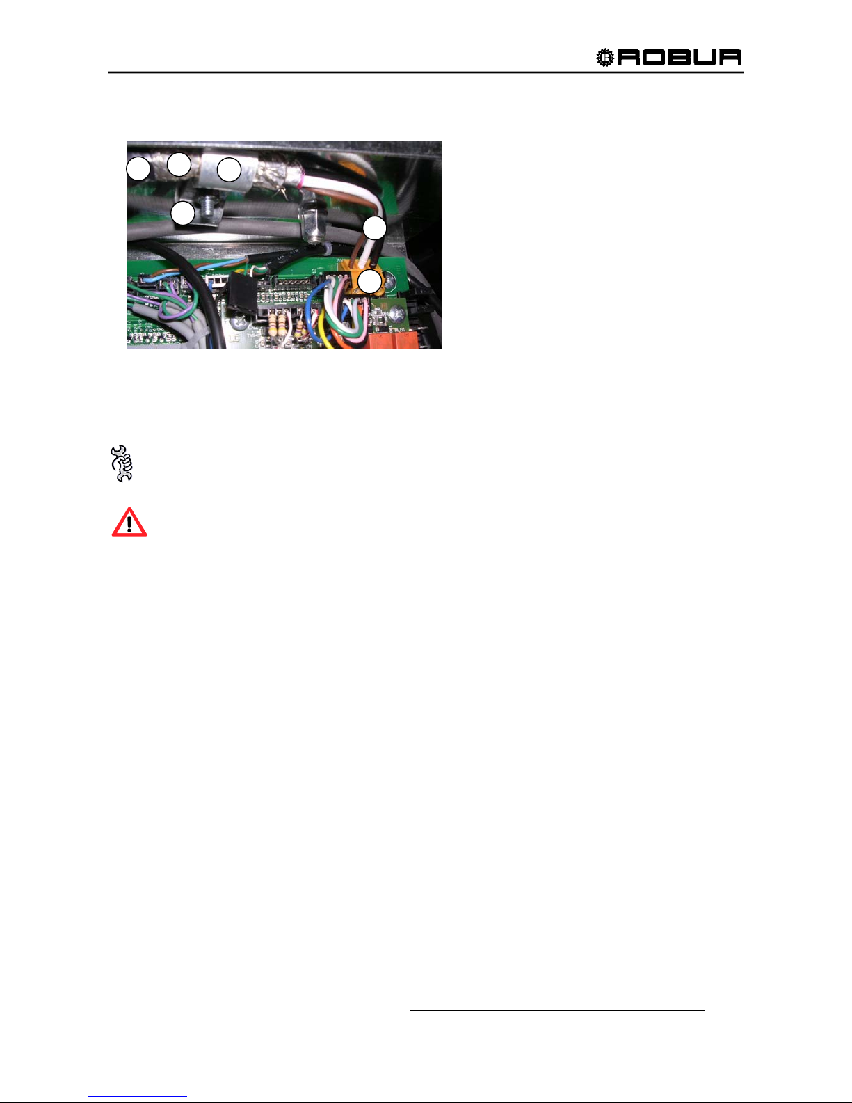
• CAN-BUS wire connection to Electronic Control board
Figure 22 – EXAMPLE OF CAN-BUS CONNECTION TO ELECTRONIC CONTROL BOARD (EXAMPLE WITH ONLY
ONE CAN-BUS WIRE)
To connect a CAN bus cable to an appliance:
You will need: The appliance (or appliances) positioned in its (or their) final location.
Before working on the electrical panel of the appliance, make sure that it is not connected to the
power supply.
1. Remove the front panel of the appliance and the cover of the electrical panel.
2. Cut the ideal length of cable for the installation so that it will not undergo bending.
3. Having chosen one end of the length of cable, remove the sheath from a length of approximately 7080 mm, taking care not to cut the shielding (metallic shield and/or aluminium sheet and, if present, the
bare connector in contact with the shield) and the wires contained within.
4. If the diameter of the cable used is not large enough to be blocked inside the cable clamp (letter C of
Figure 22 on page 45), make it larger by wrapping electrical tape over the protective outer covering in
the area adjacent to the unsheathed part (approximate diameter required: 12-13 mm).
5. Pull back the shielding in the sheathe; apply electrician’s tape to the end of the shielding as pulled
back (letter A of
Figure 22, page 45).
6. If the appliance is a terminal node of the network connect the three coloured wires to the orange
connector, as shown in detail A; of Figure 23 on page 46. Respect the correct indications L, H, GND
provided in
Table 17 on page 44, on the figure and on the diagram at the base of the connector.
7. If the appliance is an intermediate node repeat the operations from step 3 to step 6 for the other
length of cable required (so to will have two cable lengths everyone without the sheath). To interlace
between they the threads with the same color and to connect them to the orange connector, as shown
in detail B; of Figure 24 on page 46.
8. Fix the CAN bus cable (or two cables, according to the type of node being connected) to the cable
fixing bracket in the upper part of the inside of the electrical panel so that the rolled-back sheathing
makes solid contact with the metal bracket. The cables must be held firmly in place by the bracket if
pulled..
LEGEND
NB: Situation with only one CAN-BUS wire
(The figure at left, is an example of terminal node
connection to electronic control board).
A Isolated adhesive tape
B CAN-BUS wire shield
C Fixing clamp (1 CAN-BUS wire is fixed)
D Connector for CAN-BUS wire conductors
(to be removed to ease the conductors connection)
E Internal conductors (n. 3) of CAN-BUS wire
F Fixing point for eventual 2° segments CAN-BUS wire
(intermediate node)
B
C
E
D
A
F
Page 48
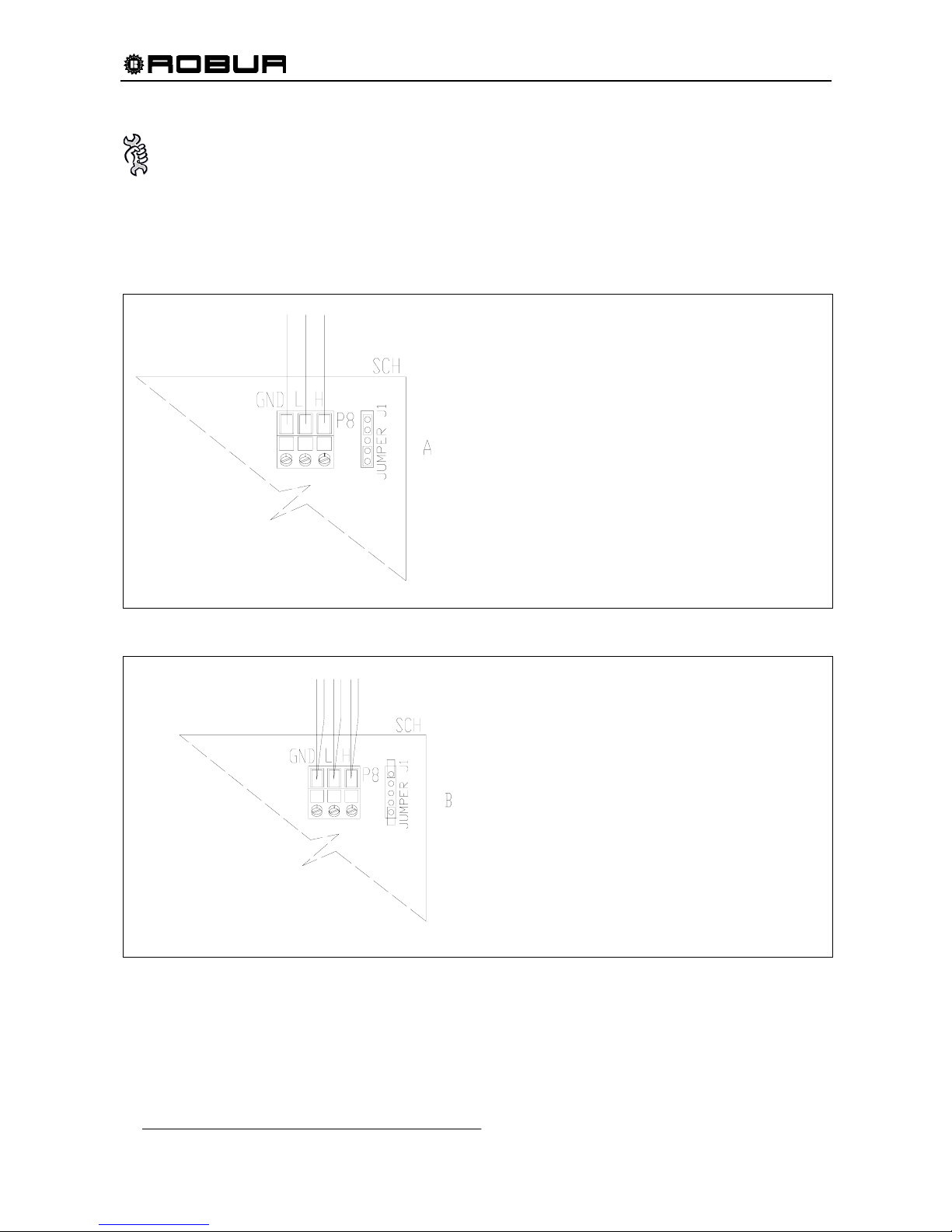
Installation, Start-Up, Adjustment and Maintenance Manual
46
To position the jumpers on the board according to the type of node being configured:
You will need: access to the electronic board.
- If the appliance is a terminal node on the network (i.e. 3 wires are inserted in the orange
connector on the board): set the jumpers as shown in detail A of Figure 23.
- If the appliance is an intermediate node on the network (i.e. 6 wires are inserted in the orange
connector on the board); set the jumpers as shown in detail B of Figure 24.
Figure 23 – DETAILED EXAMPLE OF THE CONNECTION OF ONLY ONE CAN-BUS WIRE WITH THE ELECTRONIC
CONTROL BOARD
Figure 24– DETAILED EXAMPLE OF THE CONNECTION OF TWO CAN-BUS WIRES WITH THE ELECTRONIC
CONTROL BOARD
EXAMPLE OF OPENED JUMPERS
(Intermediate node with 2 CAN-BUS wires)
GND common cable
L LOW signal parameters
H HIGH signal parameters
P8 CAN PORT / CONNECTOR
J1 jumpers (opened position)
“
CHILLER
”
EXAMPLE OF CLOSED JUMPERS
(terminal node with only 1 CAN-BUS wire)
GND common cable
L LOW signal parameters
H HIGH signal parameters
P8 CAN PORT / CONNECTOR
J1 jumpers (closed position)
Conductors
CAN-BUS wire
“
CHILLER
”
Page 49
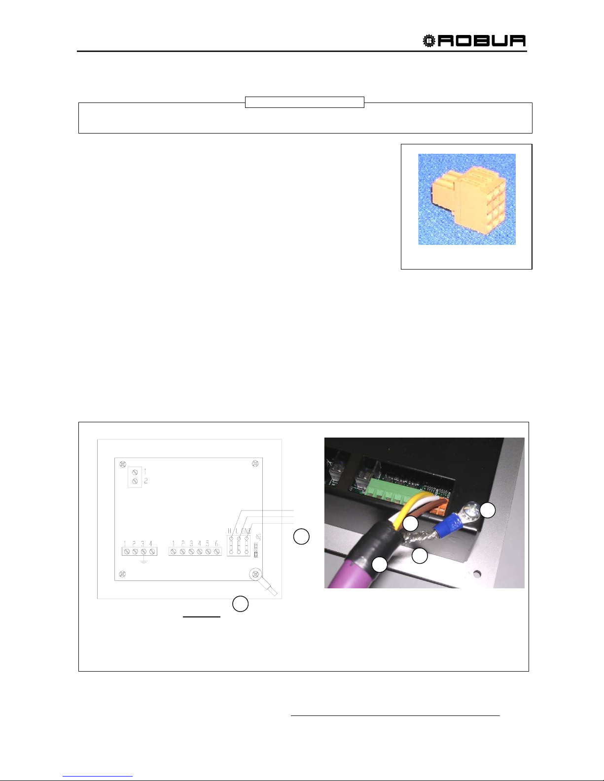
Installation, Start-Up, Adjustment and Maintenance Manual
47
• CAN-BUS wire connection to Digital Display Control (DDC)
Like the orange connector of the electronic control board, the DDC connector, too, has two different situations of
connection (see Figure 26, Figure 27 page 48). The Jumpers (J21) are closed in the factory as in 1st CASE.
1. Take from the supplied bag the orange connector of CAN Port.
2. Connect 3 conductors of CAN-BUS wire (Particular B, Figure 25)
respecting the signal/color indications as in Table 17, page 44 with
three inlets H, L, GND of the connector as in Figure 25; see also
Figure 26, page 48.
3. If one intermediate node of parameters communication network is
under connection, follow the instructions of points 3a, 3b, 3c, 3d; but
if one terminal node of parameters communication network is
under connection, go directly to point 4.
3a Connect 3 internal conductors of the other segment of CAN-
BUS wire (after cutting the sheath from terminals) with 3 inlets
H, L, GND of the DDC connector as in Figure 27, page 48.
3b Remove the back cover of the DDC unscrewing the 4 fixing screws.
3c In the electronic control board of DDC, ad just the Jumpers (J21) placed beside the orange
connector of CAN Port (P8) as in Figure 27, page 48.
3d Fix the back cover of the DDC using 4 screws
4. Engage – from the back cover hole of DDC – the orange connector of CAN Port to the DDC electronic
control board.
5a Roll up the cut shield of the above mentioned CAN-BUS wire and connect it with an eyelet terminal of
0.16” (particular C&D, Figure 25).
5b (only for intermediate node) roll up the cut shield of the other CAN-BUS wire and connect it with eyelet
terminal of 0.16” (particular C&D, Figure 25).
6. Unscrew the right bottom screw of the DDC back cover (particular D, Figure 25) and inset it to the eyelet
terminal (s) and screw it down again.
7 Isolate – with suitable adhesive tape – the shield part of the wire (particular A, Figure 25).
Figure 25 – EXAMPLE OF CAN-BUS WIRE CONNECTION TO DDC (only one entry CAN-BUS wire)
ORANGE CONNECTOR OF CAN PORT
A
B
C
D
B
D
DD
C
WARNING
LEGEND
GND Common cable A Isolated adhesive tape
L LOW signal parameters B Conductors CAN wire
H HIGH signal parameters C CAN –BUS wire shield
J21 Jumpers D Eyelet terminal fixed with screw at back cover DDC
P8
Page 50
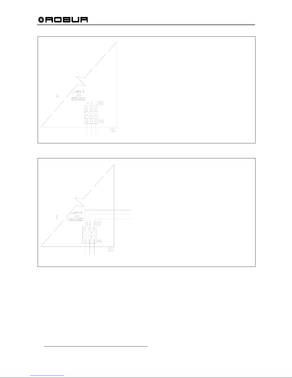
Installation, Start-Up, Adjustment and Maintenance Manual
48
Figure 26 – DETAILED EXAMPLE OF ONE CAN-BUS WIRE CONNECTION TO DDC
Figure 27 – DETAILED EXAMPLE OF TWO CAN-BUS WIRES CONNECTION TO DDC
EXAMPLE OF CLOSED JUMPERS
(Terminal node with N. 1 CAN-BUS wire)
GND common cable
L LOW parameters signals
H High parameters signals
P8 CAN PORT / CONNECTOR
J21 jumpers (closed position)
conductors
CAN-BUS Wire
EXAMPLE OF OPENED JUMPERS
(Intermediate node with N. 2 CAN-BUS wires )
GND common cable
L LOW parameters signals
H High parameters signals
P8 CAN PORT / CONNECTOR
J21 jumpers (opened position)
conductors
CAN-BUS Wire
another segment
conductors
CAN-BUS Wire
Page 51
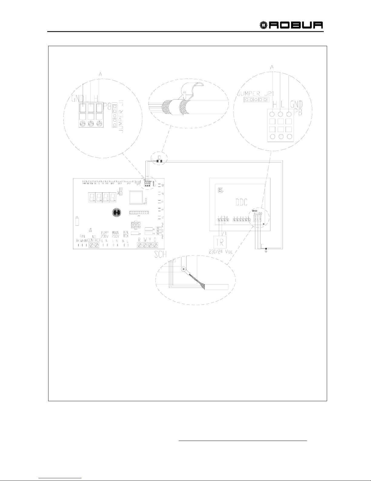
Installation, Start-Up, Adjustment and Maintenance Manual
49
Figure 28 – CONNECTION OF DDC TO N. 1 ACF60-00.
LEGEND
DDC DIRECT DIGTAL CONTROLLER FOR AYF (SUPPLIED AS ACCESSORY)
TR SAFETY TRANSORMER 230/24 Vac – 60 Hz (> 20 VA, not supplied)
GND/L/H SIGNAL PARAMETERS (COMMON/HIGH/LOW) (OF CONNECTOR P8)
J21 JUMPERS FOR CAN-BUS ON DDC
J1 JUMPER for CAN-BUS on ECB S61
Page 52
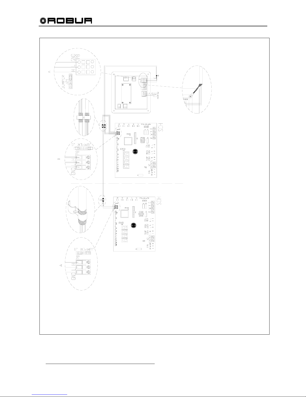
Installation, Start-Up, Adjustment and Maintenance Manual
50
Figure 29 – CONNECTION OF DDC TO N. 2 ACF60-00.
LEGEND
DDC DIRECT DIGTAL CONTROLLER FOR AYF (SUPPLIED
AS ACCESSORY)
TR SAFETY TRANSORMER 230/24 Vac – 60 Hz (> 20 VA,
not supplied)
GND/L/H SIGNAL PARAMETERS (COMMON/HIGH/LOW) (OF
CONNECTOR P8)
J21 JUMPERS FOR CAN-BUS ON DDC
J1 JUMPER for CAN-BUS on ECB S61
Page 53
Installation, Start-Up, Adjustment and Maintenance Manual
51
6. START-UP AND ADJUSTMENT
This unit should be started-up by Authorized Engineers (TAC) according to the manufacturer’s
instructions. The end-user is not authorized to perform start-up and adjustment operations.
If during the first start-up (in site) a DANGEROUS or ANOMALOUS situation is met due to non-conform
system, the start-up operations won’t be completed. The user/installer must perform the proper adjustments
indicated by authorized engineers (TAC), who will carry out the start-up.
The positive result of the first start-up (in site) is only reflecting the good operation of the unit and DDC (if
used), but doesn’t involve any responsibility concerning the correct execution of the system.
The length of the warranty is dependent upon the installation and START-UP of the unit by
Authorized Technicians (TAC). See warranty card for complete details.
DANGEROUS SITUATIONS FOR THE UNIT AND/OR PERSONS
If up on performing the 1
st
start-up, and one of the following conditions is found don’t proceed with the
start-up:
- Unit installed indoors, or in position unsafe for servicing and maintenance.
- The unit turned on and off by using the main electrical switch (not using control switch).
- Antifreeze mono-ethylene glycol not added to the water
- Unit damaged or defective due to transport and/or installation
ANOMALOUS INSTALLATION CONDITIONS FOR THE UNIT AND/OR PERSONS
The authorized Robur service (TAC) can carry out the 1st start-up, but the unit will be kept switched off
until the user/installer fully follows the manufacturer’s directions/instructions. Anomalous installation
conditions:
- Installations which show situations in contradiction to the directions/instructions of the manufacturer in
part or fully;
- Installations which show situations which result or may result as a defective unit operation.
6.1 FILLING THE WATER PIPING
To ensure correct operation of the unit and to avoid the water freezing, add 10% by volume of
inhibited mono-ethylene glycol (antifreeze) to the circulation water. Add more mono-ethylene
glycol as needed for the minimum external temperature of the installation zone (see Table 18,
page 53).
The method described below is only one of several ways that can be used to fill the hydronic circuit. A
container to mix water and mono-ethylene glycol and a water pump to drive the mixture into the hydronic
system is required; 2 valves are placed on the circuit as shown in Figure 30.
WARNING
WARNING
Page 54
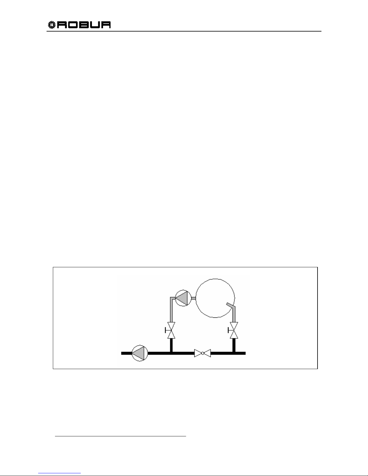
Installation, Start-Up, Adjustment and Maintenance Manual
52
1. Open air bleed(s) located at the highest point in the system. Connect a hose between the charging
pump and Valve A. Connect a hose to Valve C and place the other end of this hose into the mixing
container (See Figure 21).
2. Mix the desired concentration and volume of water/antifreeze in the container. If the container will not
hold the volume required to fill hydronic circuit, multiple “batches” must be made.
3. Close Valve B. Open Valve A and Valve C. Start charging pump to push the water/antifreeze mixture into
the hydronic system. Air will be removed through the hose on Valve C as the hydronic system fills.
Continue to fill the system until the water/antifreeze mixture returns to the mixing container via the hose
on Valve C.
4. If the volume in the mixing container is adequate to fill the hydronic system, skip to Step 14. If the
volume in the mixing container is inadequate to fill the hydronic system, close Valve A prior to air
entering the charging pump and shut the charging pump off.
5. Make a new container of water/antifreeze mixture.
6. Start the charging pump and open Valve A to continue filling hydronic system. Repeat Steps 4 through 6
as needed until hydronic system is filled or until charging pump is incapable of adding any additional
mixture due to pump discharge head limitations.
7. If the system is filled, skip to Step 14. If the system is not full, turn on the hydronic system’s pump but do
not start the unit. Jumping the N.O. CIRC. contacts on the electronic control board can start the hydronic
system’s pump.
8. “Throttle” Valve B, if necessary to continue filling the hydronic system if the system does not start filling
after the hydronic system pump was started.
9. If the volume in the mixing container is not sufficient to fill the hydronic system, close Valve A prior to air
entering the charging pump and shut both pumps off.
10. Mix new container of water/antifreeze mixture.
11. Start both pumps and open Valve A.
12. Repeat Steps 9 through 11 until the system is filled and all air is removed from the hydronic system.
13. Close Valve A and Valve C. Shut off all pumps. Open Valve B.
14. Close any manual air bleed valves.
15. Start pumps and open Valve A.
16. Add additional inhibited antifreeze/water mixture until the hydronic system has a total pressure of at least
20 psig or sufficient pressure in the system to allow a positive pressure at pump suction at all times.
17. Close Valve A and shut down both pumps.
18. Disconnect the charging pump and the mixing container.
19. The hydronic system is now charged.
Figure 30 – COMPONENTS USED IN FILLING THE HYDRONIC SYSTEM
HYDRONIC SYSTEM’S
WATER PUMP
VALVE “A”
VALVE “B”
VALVE “C”
CHARGING
PUMP
MIXING
CONTAINER
Page 55
Installation, Start-Up, Adjustment and Maintenance Manual
53
TYPE OF APPROXIMATE PERCENTAGE OF ANTIFREEZE BY VOLUME
ANTIFREEZE 20 30 40 50
MONO-ETHYLENE
GLYCOL
16°F 4°F -12°F -35°F
Table 18 – FREEZING POINTS OBTAINED BY VARIOUS CONCENTRATIONS OF MONO-ETHYLENE GLYCOL
ANTIFREEZE
As other hydronic appliances, Robur heating and cooling systems operate with grid-water of good quality. In
order to prevent any possible problem of operation or reliability caused by filling or top-up water, please refer
to codes and norms about water treatment for thermo-hydraulic installations in civil or industrial applications.
Parameters indicated in Table 19 must be complied with.
CHEMICAL AND PHYSICAL PARAMETERS OF WATER IN HAETING/COOLING SYSTEMS
PARAMETER UNIT OF ME ASUREMENT ALLOWABLE RANGE
pH \ > 7
(1)
CHLORIDES ppm < 125
TOTAL HARDNESS (CaCO3) °f < 15
IRON ppm < 0.5
(1)
COPPER ppm < 0.1
(1)
ALUMINIUM ppm < 1
LANGELIER’S INDEX \ 0 – 0.4
HARMFUL SUBSTANCES
FREE CHLORINE ppm < 0.2
(1)
FLUORIDES ppm < 1
SULPHIDES ABSENT
(1) In accordance and respecting current and local regulation
Table 19 – CHEMICAL AND PHYSICAL PARAMETERS OF WATER.
Water quality can be measured through parameters like acidity, hardness, conductivity, chlorides content,
chlorine content, iron content and the like.
WARNING !!! The presence of active chlorine in the water, in particular, can jeopardize parts of the
installation and Robur units. Therefore, please make sure that active chlorine content and total hardness are
compliant with the allowable ranges reported in Table 19.
The way the installation is operated can be the cause of possible degradation of water quality.
Moreover, abnormally massive water top-up or reintegration
can cause a drift of chemical or physical abovementioned parameters. Reintegration should not exceed 5% per year of the total amount of water. It is
advised to check regularly the water quality, especially in case of automatic or periodic top-up.
In case water treatment
is needed, this operation should be carried out by a professional or competent
person, following strictly the instructions by the manufacturer or supplier of the chemical substances for the
treatment, since dangers could arise for health, for the environment and for Robur appliances.
Several products for water treatment are available on the market.
In case washing of the pipes
is needed, this operation should be carried out by a professional or competent
person, following strictly the instructions by the manufacturer or supplier of the chemical substances for the
washing, avoiding the use of substances aggressive for stainless steel or containing/releasing active
chlorine.
Please make sure the pipes are properly rinsed in order to remove any residue of chemical substances from
the pipes.
Robur is not liable
for ensuring that water quality is always compliant with what reported in Table 19 is not’s.
Non-compliance with indications above may jeopardize the proper operation, integrity and reliability of Robur
appliances, invalidating the warranty.
For any further detail, please contact directly Robur Corporation Evansville, IN
Phone (812) 424-1800; Fax (812) 422-5117.
Page 56
Installation, Start-Up, Adjustment and Maintenance Manual
54
6.2 GAS PRESSURE ADJUSTEMENT
The manufacturer supplies the units already adjusted for a particular type of gas. The type of gas can be
checked and easily identified by looking at the marking label inside the unit. Nevertheless, before starting the
unit it is necessary to check and adjust if necessary the Gas Input (HHV) to the burner. Using the table
below, arrange the proper manifold pressure according to the local gas heating value (BTU content per cubic
foot) and specific gravity. This table is based on the correct natural Gas Input (HHV) for the model by
manifold pressure in inches of water column (in WC).
SPECIFIC GRAVITY OF NATURAL GAS
MJ CONTENT
PER CU.Meter
BTU CONTENT
PER CU.FT.
0,55 0,6 0,65 0,7
35,40 950 2,81 3,07 3,33 3,58
36,33 975 2,67 2,91 3,16 3,40
37,26 1000 2,54 2,77 3,00 3,23
38,19 1025 2,42 2,64 2,86 3,08
39,12 1050 2,30 2,51 2,72 2,93
40,05 1075 2,20 2,40 2,60 2,80
40,98 1100 2,10 2,29 2,48 2,67
41,92 1125 2,01 2,19 2,37 2,55
Nostro riferimento:
SPECIFIC GRAVITY OF NATURAL GAS
MJ CONTENT
PER CU.Meter
BTU CONTENT
PER CU.FT.
0,555
37,78 1014 2,5
Table 20 - MANIFOLD PRESSURE BASED ON GAS INPUT (HHV) OF 94,900 Btu/hr USING 0.21” ORIFICE.
The conditions referred to by the table above are for the guidance of the installer and the CSA design
certification does not cover the conditions described therein.
Note: For Propane Gas Models, follow the same instructions as given for natural gas. The manifold pressure
for propane gas should be 4.8” W.C. and adjustment is made at the gas valve regulator. Manifold pressure at
94,900 Btu/hr. input using 0.14” orifice.
GAS TYPE
NATURAL GAS LP GAS
MANIFOLD PRESSURE
2.5 WC Inches 4.8 WC Inches
NOZZLE DIAMETER
0.21” 0.14”
Table 21 - MANIFOLD PRESSURE AND NOZZLE DIAMETER
PRESSURE ADJUSTMENT PROCEDURE
1. Turn main gas valve knob to the “OFF” position.
2. Remove the plug on Outlet end of gas valve and attach pressure tap and manometer.
3. Turn power “ON,” and close control switch.
4. Wait for the burner to start up. Due to the presence of air inside the piping, it may be that the burner
does not start at the first three attempts and failing to do so the ignition system is locked out. If this
happens reset the ignition system (see dedicated procedure, end of Appendix). Repeat until all the air is
purged from the piping and the burner ignites.
5. When the burner ignites read the manometer and compare to the required pressure in
Table 20.
Page 57
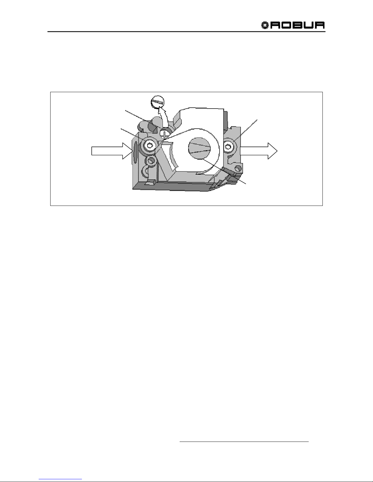
Installation, Start-Up, Adjustment and Maintenance Manual
55
6. If necessary change the manifold pressure using the gas valve regulator. The regulator is built into the
gas valve. Remove the seal screw and turn adjusting screw clockwise to increase pressure or counter
clockwise to reduce pressure. Replace seal screw after adjustment.
7. Open control switch and make sure unit is off.
8. Remove manometer and pressure tap. Replace plug in gas valve.
9. Turn unit on by closing control switch. Check all gas connections with soap for leaks.
Figure 31 – GAS VALVE
INLET
PRESSURE
TAP
PRESSURE
REGULATOR
ADJUSTMENT
REMOVE CAP SCREW FOR
PRESSURE ADJUSTMENT
OUTLET
PRESSURE
TAP
OFF
ON
GAS CONTROL
KNOB
Page 58
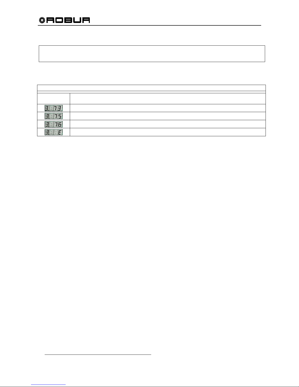
Installation, Start-Up, Adjustment and Maintenance Manual
56
6.3 CHILLED WATER TEMPERATURE REGULATION
When DDC is used, the following menu3 set-up is not to be done. It’s necessary to consult “Installation and Programming
manual of DDC - Direct Digital Controller”.
If the unit isn’t connected to a DDC, chilled water temperature regulation can be set up from menu 3 of the
S61 card (see APPENDIX: S61 electronic card).
MENU 3 – End User Adjustment
MENU
SIGNALS
DESCRIPTION OF MENU SIGNALS
Thermostat action
Cold water set point
Cold water temperature difference ∆T
Exit
Table 22 – MENU 3 PARAMETERS
The thermostat action parameter can assume 2 values: 0 and 1. When 0 is set, temperature to drive the
unit is read by the INLET probe; when 1 is set, the temperature is read by the OUTLET probe.
The set-point is intended to be the pre adjusted water temperature (in/out), when being achieved, the unit
will start the switching off cycle as (since) the conditioning request is met. This parameter can assume
values from a factory set minimum value up to 77°F.
The temperature difference is intended to be a value, which should be summed up by the pre adjusted set
point temperatures. This parameter can assume values from 1.8°F up to 14.4°F.
The obtained value represents the water temperature. According to this temperature, the conditioning
request will be re activated and then the unit will start–up again .
For example, let us suppose the following adjustments :
- Thermostat action: unit operation with outlet temperature
- set-point +44°F;
- Temp. difference 2 ;
The unit behaves as follows :
- One time during the unit operation, the water of HYDRONIC system is getting cold until the outlet water
temperature reaches +44°F (set-point temperature);
- Up on achieving that temperature, the unit will be switched off automatically.
- When the water temperature starts getting high, reaches +46°F (that is +44°F plus the temp difference
of 2) the unit will start-up again to cool the water once more until reaching +44°F, and so on.
Then, according to these adjustments the unit switches off at +44°F and starts-up at +46°F.
To set up the parameters use the encoder knob:
- To select a menu, a parameter or a value rotate the knob.
- To enter a value press the knob
(see APPENDIX: Electronic system of the ACF60-00 unit).
Page 59
Installation, Start-Up, Adjustment and Maintenance Manual
57
7. SERVICING AND MAINTENANCE
This manual is an integral and essential part of the product and must be given to the owner.
Performing correct preventive service and maintenance will help to guarantee long life of the unit with high
efficiency and low maintenance costs.
ONLY Authorized Technicians (TAC) strictly complying with the manufacturer’s instructions and
the local standards should perform maintenance and service on the UNIT internal components.
Lubrication of condenser fan, hydraulic pump, and pre-mixer motor is not recommended.
The operations described below must be performed once a year. If the unit is installed on a heavy-duty
installation (industrial plants, 24hr operation etc.), it is necessary to increase the frequency of checks and
services.
MAINTENANCE TO BE PERFORMED ON THE UNIT:
- Cleaning of the condenser /absorber coils
- Check condenser fan height
Before any type of service is performed, ALWAYS shut-off the power supply at the main switch.
CLEANING THE CONDENSER / ABSORBER COILS
It is recommended to clean the condenser / absorber coils regularly since the UNIT cooling capacity can be
greatly reduced by dirt on the coils (see Figure 32). The user, installer or service technician can perform this
operation. To clean condenser / absorber coil proceed as follows:
1. Shut off the power and gas supply.
2. Remove the covering panels.
3. Use a brush to remove dirt from the outside and inside of the condenser/absorber coils.
4. Using water pressure, wash the coils from in to out and from top to bottom. Care should be taken not to
spray electrical components or to damage the aluminum fins.
5. Check that all dirt is removed.
6. Replace the panels.
7. Turn on the power and gas supply.
8. Start unit to check for correct operation.
Do not use solvents for cleaning the condenser/absorber coils; this could cause damage to the
aluminum fins.
WARNING
NOTE
NOTE
Page 60
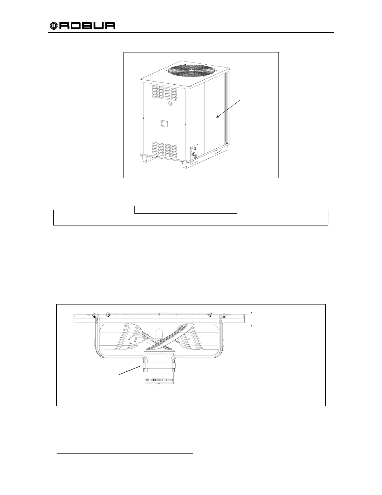
Installation, Start-Up, Adjustment and Maintenance Manual
58
NOTE: SOME DETAIL
HAS BEEN REMOVED
FOR CLARITY
SECTION VIEW
MOUNTING
STRAP
FAN BLADE EDGE –
TOP PANEL
1”1/4
Figure 32 – FINNED CONDENSER / ABSORBER
ALWAYS wear safety goggles!
BURNER CONTROL
Gas burners do not normally require scheduled servicing; however, deterioration or an accumulation of lint
may cause yellowing flame or delayed ignition. Either condition indicates that a service call is required.
CHECK CONDENSER FAN HEIGHT
For proper air flow, the distance between the top edge of the fan blade and the top panel must be 1”1/4.
If the fan is at an improper height, adjust the location of the mounting strap around the fan motor.
Figure 33 – SECTION VIEW SHOWING PROPER FAN HEIGHT
WARNING
CONDENSER /
ABSORBER COILS
Page 61
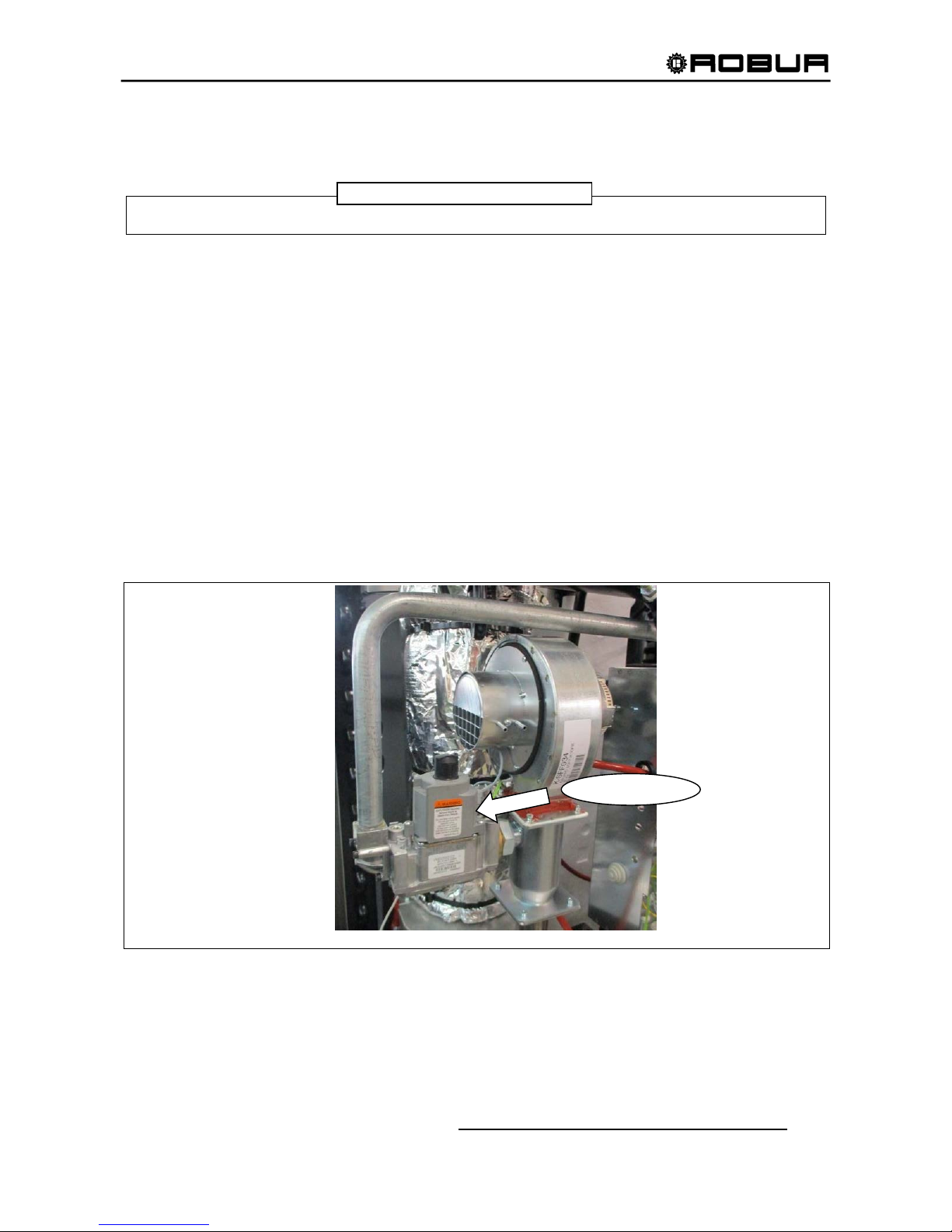
Installation, Start-Up, Adjustment and Maintenance Manual
59
8. ADAPTING TO ANOTHER GAS
ONLY an Authorized Technician can perform the operation described in this section.
If the type of gas indicated does not correspond to the type to be used (natural or propane gas) by
unit, it must be converted and adapted to the type of gas to be used. The gas orifice (nozzle) must be
changed and the gas valve must be converted.
For this operation proceed as follows:
1. Turn off the gas and electrical supply, remove front and left panel.
2. Remove the wires from the gas valve.
3. Remove the ring nut from the threaded gas nozzle.
4. Remove the gas nozzle from gas valve by removing the 4 screws from the valve flange (use 9/6 4 hex
key wrench). Put the o-ring in a safe place, to be re-used with the ne w nozzle.
5. Attach the new gas nozzle to the gas valve using the 4 sc rews to s ecure valve f lange: be sur e to put the
o-ring in the proper site.
6. Tighten the ring nut and re-attach wires to the valve.
7. Turn on the gas and electrical supply.
8. Adjust the gas pres sure f or the g as to be use d f ollowi ng the instr uctions repor ted in SECT IO N 6. 3 "GAS
PRESSURE ADJUSTMENT”.
9. Replace the stickers indicating the type of gas for which the unit is preset with the new one, which
indicates the type actually being used.
Figure 34 – GAS VALVE
NOTE
GAS VALVE
Page 62
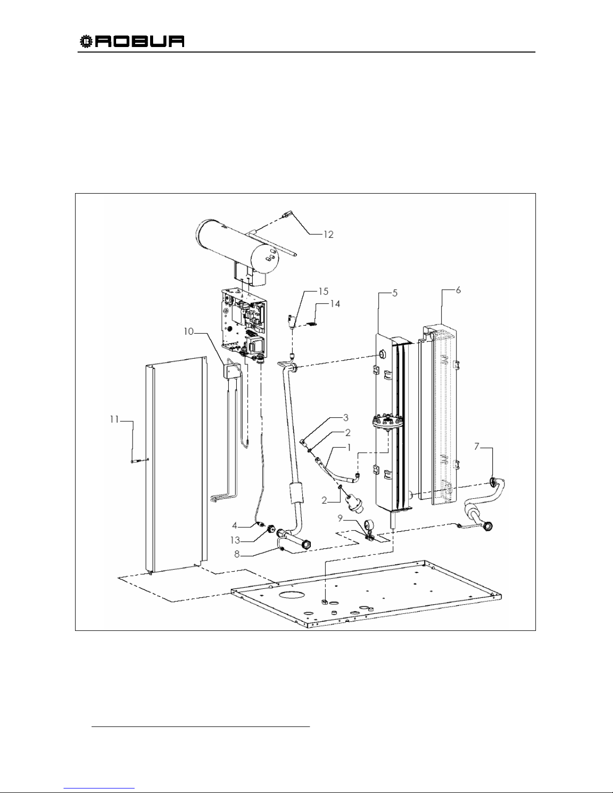
Installation, Start-Up, Adjustment and Maintenance Manual
60
9. SPARE PARTS
Below are the lists of the spare parts for ACF60-00 appliance. Each list comes after the respective exploded
drawing, which pictures each part in the list with its progressive number.
Spare parts can be ordered from Robur Corporation.
Exploded drawing n.1: INSULATING, WATER PIPES AND ACCESSORIES
Figure 35 – EXPLODED DRAWING N.1 – SEE Table 23, PAGE 61 FOR THE RELATIVE PARTS LIST.
Page 63
Installation, Start-Up, Adjustment and Maintenance Manual
61
Rif. Codice Descrizione Q.tà
1 J-TBO358 PUMP HIGH PRESSURE PIPE 1
2 N-RND016 D.3/8"x1,5 COPPER WASHER 2
3 N-BLL000 PUMP GAS SCREW 3/8” 1
4 J-FLS009 WATER FLOWSWICH FOR S61 1
5 C-CBN091 ABSORBER FRONT-SIDE INSULATING 1
6 C-CBN092 ABSORBER REAR-SIDE INSULATING 1
7 R-TBO418 WATER DELIVERY PIPE 1
8 R-TBO420 WATER RETURN PIPE 1
9 K-MNM002 DIFFERENTIAL MANOMETER KIT 1
10 J-TRS007 IGNITER TRANSFORMER 1
11 E-LMP013 SIGNAL LIGHT 230V WITH FAST-ON 1
12 G-VLV032 PRESSURE RELIEF VALVE 1
13 R-GFS001 FLOWSWICH CLAMPING RING NUT 1
14 L-STF189 AIR BREATHER VALVE BRACKET 1
15 H-VLV000 AUTOMATIC AIR BREATHER VALVE 1
Table 23 – SPARE PARTS PICTURED IN Figure 35: INSULATING, WATER PIPES AND ACCESSORIES
Page 64
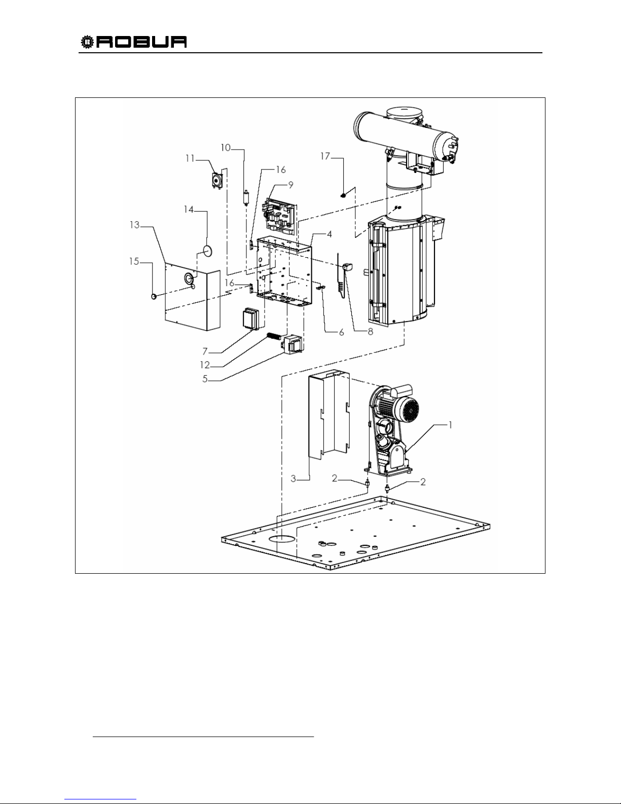
Installation, Start-Up, Adjustment and Maintenance Manual
62
Exploded drawing n.2: ELECTRICAL BOX AND PUMP
Figure 36 – EXPLODED DRAWING N.2 – SEE Table 24, PAGE 63 FOR THE RELATIVE PARTS LIST.
Page 65
Installation, Start-Up, Adjustment and Maintenance Manual
63
Rif. Codice Descrizione Q.tà
1 R-PMP009 60 Hz OIL PUMP 1
2 J-NTV000/B MX20/15 VIBRATION DAMPING 2
3 J-CRT003 PUMP CARTER 1
4 L-BQD018 ELECTRIC PANEL BASE 1
5 E-TRS013 60 Hz 208-240/24V/40VA ELECTRICAL TRANSFORMER 2
6 L-STF149 GROUND CONNECTION BRACKET 1
7 E-CNT031 24 Vac, 60Hz, MICROPROCESSOR BASED HSI CONTROL 1
8 J-TLT020 COMBUSTION CHAMBER THERMOSTAT 1
9 E-SLT040 S61CF24 ELECTRICAL BOARD 1
10 E-CND011 CONDENSER 12.5 µF 450 V 1
11 G-PRS000 AIR PRESSURE SWITCH ACF60.2 60 Hz 1
12 E-MRS020 9 STUD TERMINAL BOARD WITH REED 1
13 L-CQD011 ELECTRIC BOX COVER 1
14 C-12100960 INSPECTION HOLE GLASS 1
15 N-TPP019 D.25 PROTECTION CAP 1
16 N-CRN000 ELECTRIC BOX HINGE 2
17 J-TLT015 LIMIT THERMOSTAT FOR GENERATOR 1
Table 24 – SPARE PARTS PICTURED IN Figure 36: ELECTRICAL BOX AND PUMP
Page 66
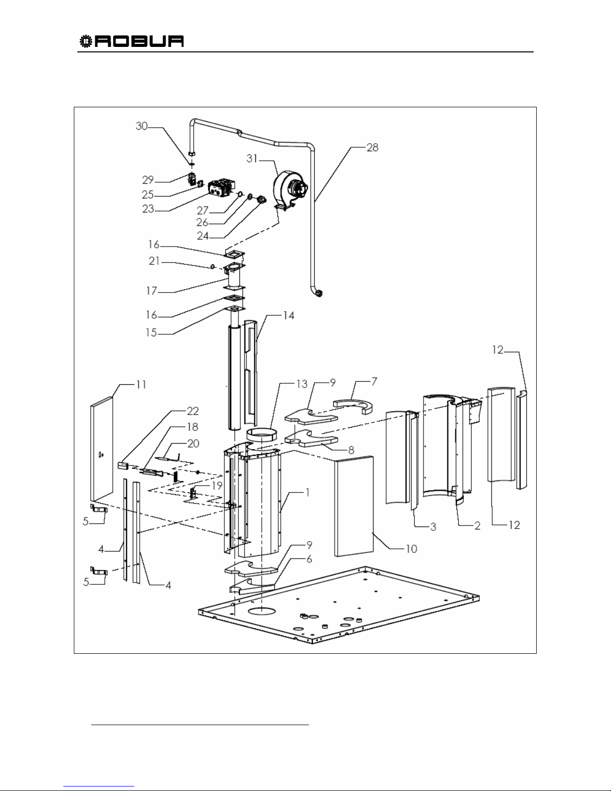
Installation, Start-Up, Adjustment and Maintenance Manual
64
Exploded drawing n.3: COMBUSTION CHAMBER AND GAS SYSTEM
Figure 37 – EXPLODED DRAWING N.3 – SEE Table 25, PAGE 65 FOR THE RELATIVE PARTS LIST.
Page 67
Installation, Start-Up, Adjustment and Maintenance Manual
65
Rif. Codice Descrizione Q.tà
1 J-CCM026 FRONT COMBUSTION CHAMBER ASSY 1
2 S-CMR000 REAR COMBUSTION CHAMBER ASSY 1
3 H-CMR002 COMB. CHAMBER INTERNAL CONVEYOR 1
4 L-STF120 RETAINER BURNER 2
5 L-MFS000 BURNER TUBE CLIP 2
6 C-CBN040 FRONT BOTTOM INSULATION 1
7 C-CBN038 REAR UPPER INSULATION 1
8 C-CBN037 FRONT-TOP INSULATION 1
9 C-CBN042 COMBUST. CHAMBER BASE INSULATION 2
10 C-CBN080 RIGHT COMBUST. CHAMBER INSULATION 1
11 C-CBN081 LEFT COMBUST. CHAMBER INSULATION 1
12 C-CBN039 COMB. CHAMBER REAR-SIDE INSULATION 2
13 C-CBN041 COMB. CHAMBER/GENERATOR INSULATION 1
14 J-CBN029 BURNER INSULATION 1
15 J-BRC017 BOILER BURNER 1
16 J-GRN028 BURNER UNION TRIMMING 2
17 R-DFF009 INCLINED AIR-GAS MIXER 1
18 J-LTT047 SPARKLING ELECTRODE 1
19 C-GRN086 SENSOR FLAME ELECTRODE GASKET 1
20 J-LTT046 SENSOR FLAME ELECTRODE 1
21 N-GRG006 2075 NB 70 O-RING 1
22 J-CSL000 D.11/16 x 50 CERAMIC INSULATION 1
23 G-VLV052 24 VAC GAS CONTROL VALVE 1
B-GLL150 Ø 5.3 METHANE NOZZLE 1
24
B-GLL153 Ø 3.6 GPL NOZZLE 1
25 C-GRN041 24x24 GAS PIPE GASKET 1
26 C-GRN040 1” GASKET 1
27 N-GRG000 3087 NBR NT 70 O-RING 1
28 R-TBO645 GAS TUBE COMPONENT 1
29 G-FLN019 90° ½“ NPT GAS VALVE FLANGE 1
30 C-GRN057 CENTELLEN 200 ¾” GASKET 1
31 K-SFF038 BLOWER KIT 1
Table 25 – SPARE PARTS PICTURED IN Figure 37: COMBUSTION CHAMBER AND GAS SYSTEM
Page 68
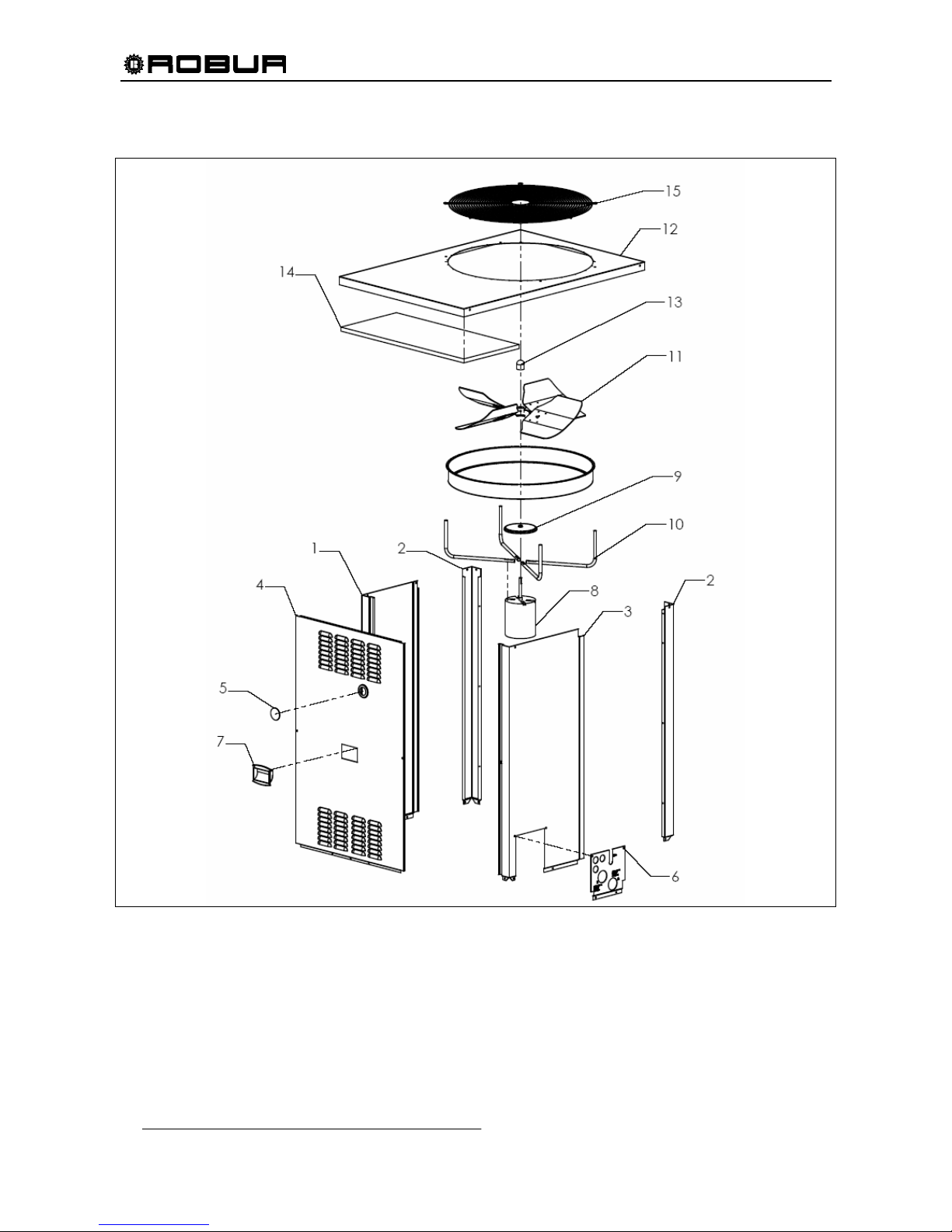
Installation, Start-Up, Adjustment and Maintenance Manual
66
Exploded drawing n.4: PANELS KIT
Figure 38 – EXPLODED DRAWING N.4 – SEE Table 26, PAGE 67 FOR THE RELATIVE PARTS LIST.
Page 69
Installation, Start-Up, Adjustment and Maintenance Manual
67
Rif. Codice Descrizione Q.tà
1 P-MNS035 PAINTED FRONT-LEFT COLUMN 1
2 P-MDS004 PAINTED BACK RIGHT-LEFT COLUMN 2
3 P-MND020 PAINTED FRONT-RIGHT COLUMN 1
4 P-PNF063 COMPLETE PAINTED FRONT PANEL 1
5 C-12100960 INSPECTION HOLE GLASS 1
6 L-PST068 SILK SCREENED SERVICE PLATE 1
7 N-MNG000 PANELS HANDLE 1
8 E-MTR056 60 Hz FAN MOTOR 1
9 V-PRT000 60 Hz MOTOR RAIN SHIELD 1
10 L-STF210 60 Hz FAN MOTOR BRACKET 4
11 V-VNT025 BLADE ASSEMBLY – FAN – 26” Ø – 60 Hz 1
12 P-CPR048 PAINTED SUPERIOR PANEL 1
13 N-TPP061 Ø33.4 H.25 VINYL CAP 1
14 C-CBN028 380X840 SUPERIOR PANEL INSULATION 1
15 J-GPR000 FAN GRID 1
Table 26 - SPARE PARTS PICTURED IN Figure 38: PANELS KIT
Page 70
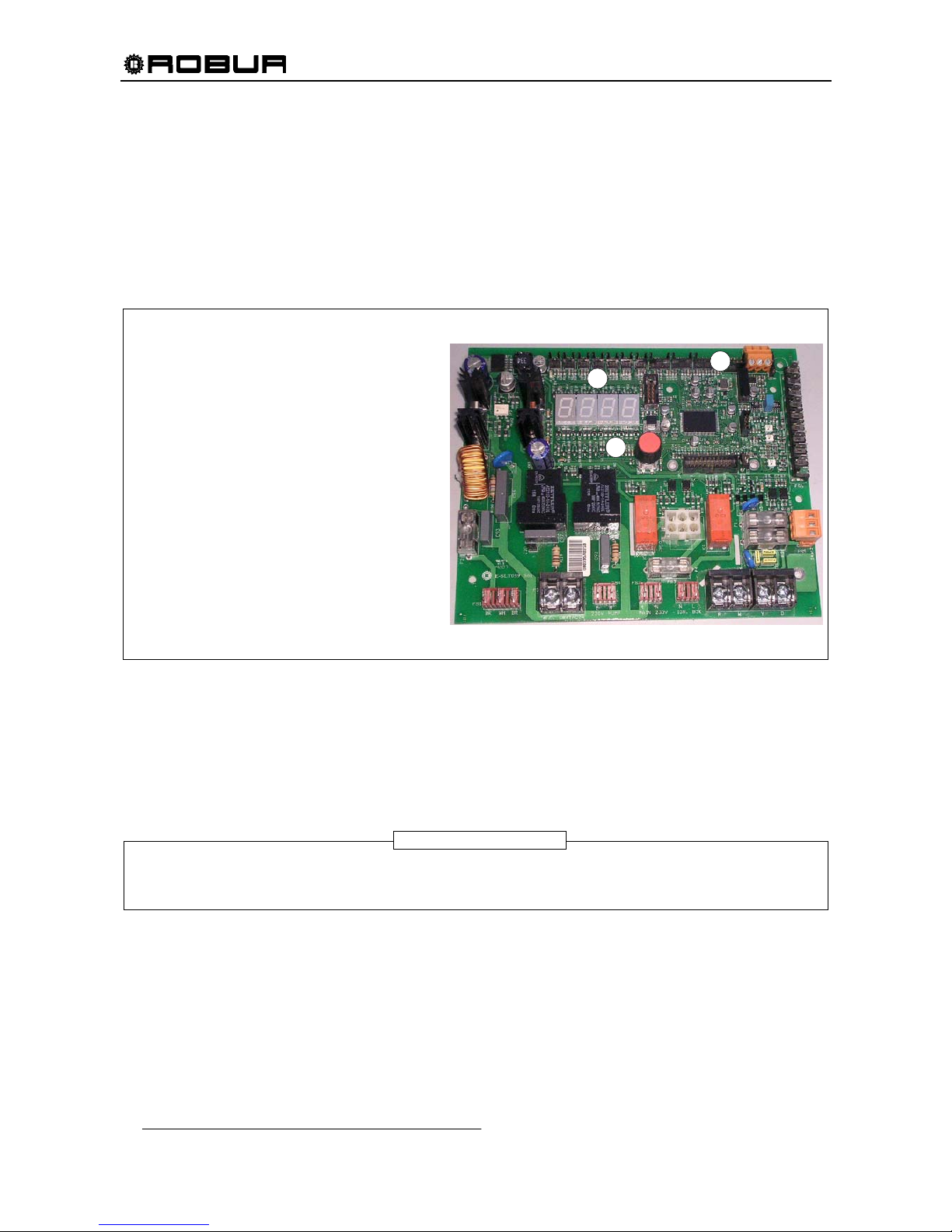
Installation, Start-Up, Adjustment and Maintenance Manual
68
10. APPENDIX
ELECTRONIC SYSTEM OF THE ACF60-00 UNIT
The electronic control board of the unit is placed inside the electrical box and is equipped with a 4 digits
display, a regulating knob (encoder) and a terminal set (CAN PORT) for the remote connection.
The DISPLAY (particular A) shows the operation data (example: chilled water temperature) and possible
anomalies, through the visualization of the unit codes.
Besides, It is possible to visualize all relative available information (data, parameters, values, etc.).
Figure 39 – ELECTRONIC CONTROL BOARD DETAIL
Rotating and pressing the REGULATING KNOB (particular B) allows the scrolling and selection of the
information on the display.
Through the regulating knob and Display, operation management and control take place.
The CAN PORT (particular C) allows the connection, by one can-bus wire, between the electronic control
board and DDC (available as accessory). When such connection is made, the operation management and
control of the unit takes place only through the DDC.
The electronic control board is placed inside the electrical box of the unit and is visible from the front panel.
To interact with the regulating knob (encoder) of the electronic control board, it is necessary to remove the front panel of the unit
and, without opening the electrical box, to act on the encoder by the supplied tube of about 4-
3
/4”.
B
A
C
Electronic Control Board S 61
LEGEND
A 4 digits DISPLAY for visualizing operational
and unit codes
B REGULATING KNOB (Encoder) for
scrolling/selection of data
C
CAN PORT for the connection to DDC
NOTE
Page 71
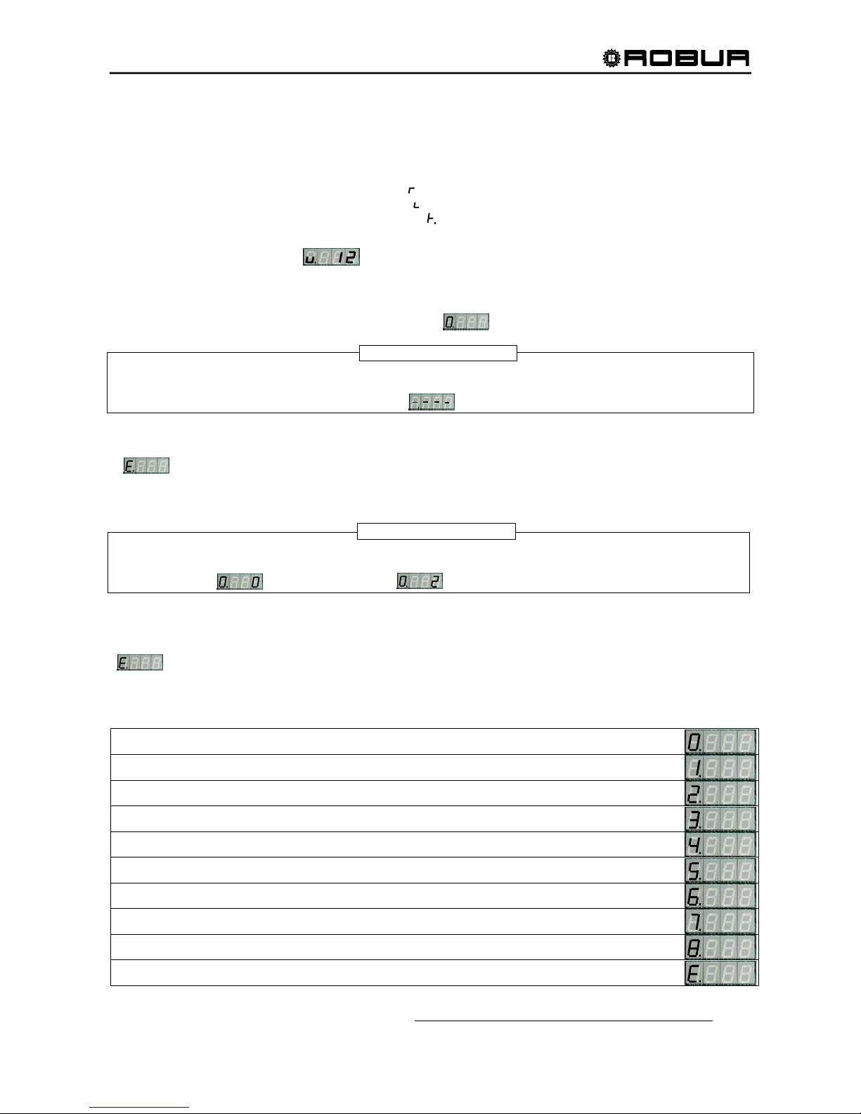
Installation, Start-Up, Adjustment and Maintenance Manual
69
Operation Management And Control
The Display of the electronic control board, during the normal operation, shows in alternative mode the
following information:
Water inlet temperature (after the symbol )
Water outlet temperature (after the symbol )
Temperature difference ∆T (after the symbol )
If anomalies are found, the electronic control board will show them on the display and will visualize the
relative flashing unit codes. (i.e. ).
Until the unit code is not deactivated, display will show the unit code flashing. When there are more than one
unit code deactivated, they will be visualized in alternative mode and flashing.
To enter the menu of electronic control board (visualization menu) press its ENCODER once: on the display
the 1st menu entry will be visualized (menu 0, shown as ).
If any information (menu, menu entries, parameters and/or values, etc.) is visualized on the display in flashing mode, it means
that this information couldn’t be entered.
When an information is not available, the display visualizes : .
Rotating the encoder, all the other menu will be visualized on the display.
To exit and return to the precedent level, it is necessary to select the letter “E”
( ) by pressing the encoder.
To enter in menu and visualize menu entries it’s necessary to stop on the desired menu and press the
encoder: on the display the first menu entry of the same menu will be visualized .
The menu entries will be identified on the display of the electronic control board through a number, where its maximum value is 3
digits (lined up at right). The visualization is characterized by the presence (on the 1st digit of display) of the menu identification
number (example : indicates entry 0, menu 0; indicates menu entry 2, menu 0).
By rotating the encoder, all the other menu entries of the same menu will be visualized on the display.
To exit and return to the precedent level (default visualization), it is necessary to select the letter “E”
( ) by pressing the encoder.
MENU DESCRIPTION
The electronic control board presents nine menu (from 0 to 8), as follows:
Table 27 – S61 MENUS
NOTE
NOTE
Menu 0: Data Visualization
Menu 1: Parameter Visualization
Menu 2: Actions
Menu 3: End User Adjustment
Menu 4: Adjustment by (Assistance Centers)
Menu 5: Adjustment (by Assistance Centers)
Menu 6: Unit Type Adjustment (by Assistance Centers)
Menu 7: Digital Inlet Visualization
Menu 8: Set Password (not manageable)
“E”: Exit
Page 72
Installation, Start-Up, Adjustment and Maintenance Manual
70
MENU 0, 1 and 7 are “Visualization Menu” (data and parameters are read-only). In menu 0 it’s possible to
visualize the unit operation data detected from the electronic control board; In menu 1 it’s possible to realtime visualize the unit operation data and the unit management. In menu 7 a number will represent the state
of digital Inlet.
MENU 2 is an “Execution Menu”; through this menu it’s possible execute actions like reset ignition control
box and reset errors, as consequence of anomalies detected by the unit. The code will be visualized on the
display of the electronic control board.
MENU 3, 4, 5 e 6 are “Adjustment Menu”, to adjust the contained information. Menu 3 is relative to the enduser, who can eventually (if allowed) modify the value of parameters; an example are cold water set point
and the water temperature difference setup.
MENU 4, 5 e 6 are only to be managed by Robur Technical Assistance authorized Centers (TAC).
The electronic control board has three fuses for circuit protection. If the electronic control board does not
start up or the condenser fan does not run, remove power from the unit and check the condition of the
fuses. The S61 board requires a 10A (condenser fan) and two 2A fuses (electrical board). The size of the
fuse is labeled on the electronic control board next to the respective fuse holder.
The maximum current carrying capacity of the N.O. Contact is 4A. Refer to Section 5.2, Pump Wiring.
An isolation relay MUST be used to separate the UNIT transformer from additional equipment having a
transformer or damage to the S61 board will occur. Refer to Section 5.3, Control Switch Wiring.
IGNITION CONTROL BOX
When power is supplied to the unit (to the “R” terminal on the ignition control box), ignition control will reset,
perform a self check routine, flash the diagnostic LED, and enter thermostat scan state.
When the control switch is closed, the electronic control board will energize the ignition control box starting
the ignition sequence (24 volts applied to the “W” terminal on the ignition box).
The ignition control box will check the differential air pressure switch for open contacts.
- If the differential air pressure switch contacts are closed and stay closed for 30 seconds, an
air flow fault will be appear The diagnostic LED on the ignition control box indicates this fault.
In this mode, the ignition control box pre-mixer blower will not start.
If the pressure switch contacts are open, the ignition control box pre-mixer blower will instead start.
- An air flow fault will occur if the air pressure switch contacts remain opened for 30 seconds
after the pre-mixer blower start. The diagnostic LED on the ignition control box indicates this
fault. In this mode, the ignition control box will keep the pre-mixer blower energized.
If the air pressure switch contacts close after the pre-mixer blower starts (normal operation), a pre-purge
delay begins and the ignition sequence continues.
NOTE
WARNING
WARNING
Page 73
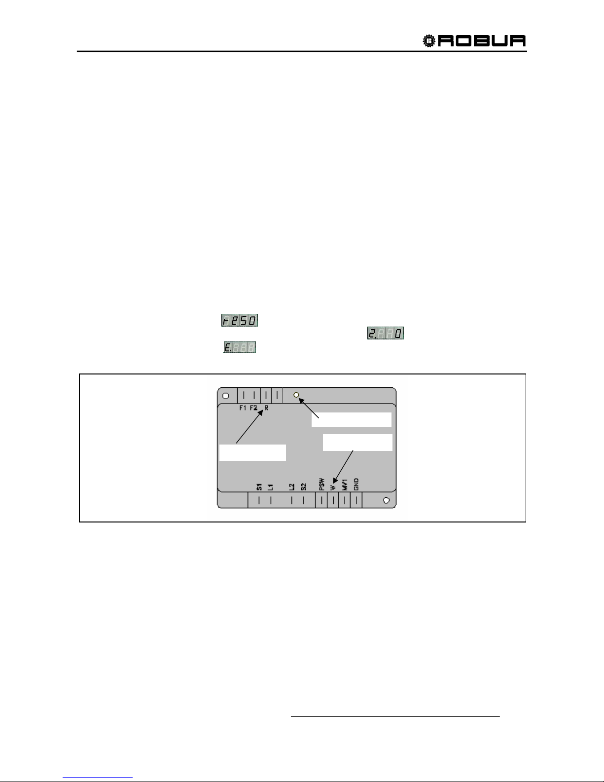
Installation, Start-Up, Adjustment and Maintenance Manual
71
Next, the ignition control box energizes an ignition transformer that generates a high intensity spark at the
igniter to ignite the gas/air mixture. Simultaneously, the gas valve is energized, allowing the flow of gas to the
burner.
The ignition control box continuously monitors the flame sensor for ignition. If the flame sensor detects flame,
the ignition transformer is de-energized immediately and the gas valve and pre-mixer blower remain
energized.
Should the burner fail to light, or flame is not detected during the first trial for ignition, the gas valve and
ignition transformer are de-energized and the ignition control box begins an inter-purge delay before another
ignition attempt. The control will attempt two additional ignition trials (total of 3 ignition trials) before going
into lockout. Upon lockout, the gas valve will de-energize immediately and the pre-mixer blower will turn off.
The thermostat (“W” terminal), air pressure switch and burner flame are constantly monitored to assure
proper system operation. When the call for flame has ended (24volts removed from “W” terminal on ignition
control), the gas valve is de-energized immediately. The ignition control then senses loss of flame and deenergizes the pre-mixer blower.
To reset the ignition box from menu2:
- To enter menu2, proceed as indicated above.
- In menu2, push the encoder on menu signal 0 to enter the reset ignition control box option, visualized
by the flashing code “reS0” ( ); push the encoder to confirm the reset operation.
- After confirmation, the display visualizes again the menu signal .
- To exit, select the letter “E” ( ) and push the encoder.
Figure 40 - IGNITION CONTROL BOX
“R” TERMINAL
DIAGNOSTIC LED
“W” TERMINAL
FC±
Page 74
Installation, Start-Up, Adjustment and Maintenance Manual
72
TABLE OF OPERATING CODES GENERATED BY ELECTRONIC BOARD
(firmware version 3.029)
COLD MODULE
U 1
GENERATOR THERMOSTAT LIMIT TEMPERATURE
CODE GENERATED BY: HIGH temperature detected by limit thermostat on body of generator.
RESET METHOD: Reset limit thermostat manually: AYF operation will be restored automatically when the cause ceases.
E 1
GENERATOR THERMOSTAT LIMIT TEMPERATURE
CODE GENERATED WHEN: Code
U 1 is active for 1 hour, or U 1 intervenes 3 times in 2 hours of operation.
RESET METHOD: Contact ROBUR TAC.
U 2
EXHAUST FUMES THERMOSTAT
CODE GENERATED BY: HIGH temperature detected by exhaust fumes thermostat.
RESET METHOD: Reset occurs automatically when the condition that generated the code ceases.
E 2
EXHAUST FUMES THERMOSTAT
CODE GENERATED WHEN: code
U 2 is active for 1 hour, or generated 3 times in 2 hours of operation.
RESET METHOD: Reset may be performed via DDC (or via S61 board via menu 2, menu item 1). If codes
U 2 and/or E 2
occur again, contact ROBUR TAC.
U 3
COLD WATER ANTIFREEZE THERMOSTAT
CODE GENERATED BY: LOW temperature detected by cold outlet water sensor.
RESET METHOD: Reset occurs automatically when the condition that generated the code ceases.
U 4
INADEQUATE VENTILATION / CONDENSER OVERHEATING
CODE GENERATED BY: (TCN - TA) values > limit set.
RESET METHOD: Reset occurs automatically 20 minutes after the code is generated.
E 4
INADEQUATE VENTILATION / CONDENSER OVERHEATING
CODE GENERATED WHEN: Code
U 4 is generated twice in 2 hours of operation.
RESET METHOD: Carry out appropriate checks. Reset may be performed via DDC (or via S61 board, menu 2, menu item
1). If the code persists, contact ROBUR TAC.
E 5
HIGH AMBIENT TEMPERATURE
CODE GENERATED BY: HIGH temperature detected by ambient temperature sensor.
RESET METHOD: Reset occurs automatically when the condition that generated the code ceases.
U 6
LOW AMBIENT TEMPERATURE
CODE GENERATED BY: LOW temperature detected by ambient temperature sensor.
RESET METHOD: Reset occurs automatically when the condition that generated the code ceases.
Page 75
Installation, Start-Up, Adjustment and Maintenance Manual
73
U 7
HIGH CONDENSER INLET TEMPERATURE
CODE GENERATED BY: HIGH temperature detected by condenser inlet temperature sensor (T> limit set: menu 1, menu item 66)
RESET METHOD: Reset occurs automatically when the condition that generated the code ceases.
E 7
HIGH CONSENSER INLET TEMPERATURE
CODE GENERATED WHEN: Code
U 7 is active for 1 hour, or U 7 code is generated 12 times in 2 hours of operation.
RESET METHOD: (with central flame control unit on)
E 8
FLAME CONTROL UNIT ERROR
CODE GENERATED BY: Code E12 on cold module and condenser inlet temperature increasing by over 18 °F (10 °C) within 1
hour.
RESET METHOD: Carry out appropriate checks. Reset may be performed via DDC (or S61 board via menu 2, parameter 1).
If the code persists, contact ROBUR TAC.
U 10
COLD WATER FLOW SWITCH: insufficient chilled water flow
CODE GENERATED BY: Insufficient cold water flow rate (circulator on and flow switch open).
RESET METHOD: Reset occurs automatically when correct flow rate is restored.
E 10
COLD WATER FLOW SWITCH: insufficient chilled water flow
CODE GENERATED WHEN: Code
U 10 is generated 5 times since appliance was powered, or code U 10 is active for one hour.
RESET METHOD: Reset may be performed via DDC (or S61 board via menu 2, parameter 1). If the code persists, contact
ROBUR TAC.
U 11
INSUFFICIENT ROTATION OF OIL HYDRAULIC PUMP
CODE GENERATED BY: Insufficient rotation of oil hydraulic pump.
RESET METHOD: Reset occurs automatically 20 minutes after the code is generated.
E 11
INSUFFICIENT ROTATION OF OIL HYDRAULIC PUMP
CODE GENERATED WHEN: code
U 11 is generated twice in 2 hours of operation.
RESET METHOD: Reset may be performed via DDC (or S61 board via menu 2, parameter 1). If the code persists, contact
ROBUR TAC.
U 12
FLAME CONTROL UNIT ARREST
CODE GENERATED BY: Failure of burner to ignite.
RESET METHOD: Reset occurs automatically when the electrovalve opens again (new attempt at ignition) or after code is
active for 5 minutes.
E 12
FLAME CONTROL UNIT ARREST
CODE GENERATED BY: Flame arrest signal.
RESET METHOD: Reset may be performed via DDC (or S61 board via menu 2, parameter 0). If the code persists, contact
ROBUR TAC.
Page 76
Installation, Start-Up, Adjustment and Maintenance Manual
74
E 16
OUTLET WATER TEMPERATURE SENSOR DEFECTIVE
CODE GENERATED BY: Fault (interruption or short circuit) on outlet water temperature sensor.
RESET METHOD: Reset may be performed via DDC (or S61 board via menu 2, parameter 1). If the code persists, contact
ROBUR TAC.
E 17
COLD INLET WATER TEMPERATURE SENSOR DEFECTIVE
CODE GENERATED BY: Fault (interruption or short circuit) on condenser inlet water temperature sensor.
RESET METHOD: Reset may be performed via DDC (or S61 board via menu 2, parameter 1). If the code persists, contact
ROBUR TAC.
E 18
CONDENSER OUTLET TEMPERATURE SENSOR DEFECTIVE
CODE GENERATED BY: Fault (interruption or short circuit) on condenser outlet temperature sensor.
RESET METHOD: Reset may be performed via DDC (or S61 board via menu 2, parameter 1). If the code persists, contact
ROBUR TAC.
E 20
CONDENSER INLET TEMPERATURE SENSOR DEFECTIVE
CODE GENERATED BY: Fault (interruption or short circuit) on condenser inlet temperature sensor.
RESET METHOD: Reset may be performed via DDC (or S61 board via menu 2, parameter 1). If the code persists, contact
ROBUR TAC.
E 28
GAS SOLENOID VALVE EXCITED WHEN THE FLAME CONTROL BOX IS LOCKED
CODE GENERATED BY: The flame control box is locked (E 12) but the gas solenoid valve is excited. In this case the flame control
box is reset (E 12 resets)
RESET METHOD: Reset may be performed from the DDC (or from the S61 board via menu 2, parameter 1). If the code
persists, contact authorised ROBUR TAC.
U 29
GAS ELECTROVALVE WITHOUT ELECTRICAL POWER
CODE GENERATED WHEN: Gas electrovalve is off for 5 seconds (with central flame control unit on).
RESET METHOD: Reset occurs automatically if the gas electrovalve switches on again within 10 minutes (with central flame
control unit on).
E 29
GAS ELECTROVALVE WITHOUT ELECTRICAL POWER
CODE GENERATED WHEN: Code
U 29 is active for more than 10 minutes (with central flame control unit on).
RESET METHOD: Carry out appropriate checks. Reset may be performed via DDC (or S61 board via menu 2, parameter 1).
If the code persists, contact ROBUR TAC.
U 32
WATER TEMPERATURE TOO LOW
CODE GENERATED BY: The warning appears when the water temperature is lower than the operational limits (cooling).
RESET METHOD: Reset occurs automatically with 3.6°F hysteresis for all the units.
Page 77
Installation, Start-Up, Adjustment and Maintenance Manual
75
U 51
ANTIFREEZE FUNCTION ACTIVATED – COOLING MODULE
Activation takes place only if the cold module is off and the antifreeze function is enabled (see menu 1, parameter 77).
CODE GENERATED WHEN: Inlet or outlet water temperature of the cold module falls below 39.2 °F (4 °C - the code generated signals
that the antifreeze function has been activated).
In this case the antifreeze function activates the plant water circulator.
RESET METHOD: Reset (deactivation of antifreeze function) occurs automatically when, with only the circulator on, the inlet
and outlet water temperatures return to over 41 °F (5 °C - in this case the circulator switches off), or if the
function itself is disabled.
U 77
COLD MODULE FLOW SWITCH "ON"
CODE GENERATED BY: The flow switch of the cold module detects that water is present in the plant , when (and only in this
situation) the appliance is configured as a 2-pipe cold-hot plant and the plant is operating in hot mode at
that moment.
The code (
U 77) is disabled when the antifreeze function is active.
RESET METHOD: Reset occurs automatically when the condition that generated the code ceases.
ELECTRONIC BOARD
U 80
INCOMPLETE PARAMETERS
CODE GENERATED BY: Incomplete parameters.
RESET METHOD: The code remains active until operating parameters have been entered and completed. Contact ROBUR
TAC.
NB: If the board is replaced, code E80 may appear: this means that AY/AYF characterisation data has not been entered.
E 80
INVALID PARAMETERS
CODE GENERATED BY: Invalid parameters or damage to parameter memory.
RESET METHOD: Reset is automatic when the correct parameters are entered.
If the code persists, contact the ROBUR TAC: if the parameters are incorrect, it is necessary to enter and
complete the operating and characterisation parameters; if the memory is damaged it is necessary to
replace the board.
U 81 - U 82
INVALID BANK 1 DATA - INVALID BANK 2 DATA
CODE GENERATED BY: Invalid Bank 1 data - Invalid Bank 2 data.
RESET METHOD: Reset occurs automatically 5 seconds after the code is generated.
E 81 - E 82
INVALID BANK 1 DATA - INVALID BANK 2 DATA
CODE GENERATED BY: Invalid Bank 1 data - Invalid Bank 2 data.
RESET METHOD: Reset may be performed via the S61/AY10 board via menu 2, parameter 1 or 21.
If the code persists, contact ROBUR TAC.
E 84
FAULTY CONNECTIONS OF 24 Vac TRANSFORMER OR FUSES
CODE GENERATED BY: Damage to 1 of the 2 24-0-24 Vac input fuses or one of 24-0-24 Vac wires to the board not supplying
current.
RESET METHOD: Check 24-0-24 Vac fuses and electrical power connections on the board. Reset may be carried out via
DDC (or via S61 board via menu 2, menu item 1). If the code persists or occurs again, contact ROBUR
TAC.
Page 78
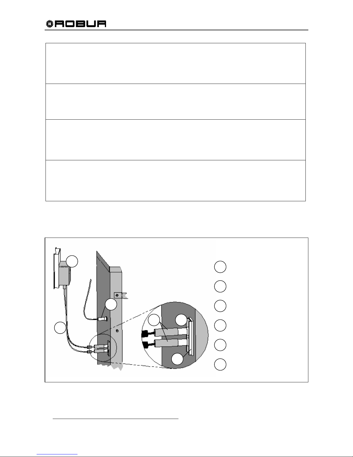
Installation, Start-Up, Adjustment and Maintenance Manual
76
E 85
INCORRECT MODULE TYPES (from menu 6)
CODE GENERATED WHEN: The module type set (from menu 6) does not correspond to the one managed by the board.
RESET METHOD: Reset occurs automatically when the correct parameters are entered.
If the code persists, contact ROBUR TAC.
E 86 - E 87 - E 88 - E 89
MEMORY TEST UNSUCCESSFUL
CODE GENERATED BY: Processor error.
RESET METHOD: Contact ROBUR TAC.
E 90
AMBIENT TEMPERATURE SENSOR DEFECTIVE
CODE GENERATED BY: Interruption or short circuit of ambient temperature sensor.
RESET METHOD: Reset may be performed via DDC (or S61 board via menu 2, menu item 1). If the code persists, contact
ROBUR TAC.
E 91
BOARD DEFECTIVE
CODE GENERATED WHEN: One of the following is absent: serial number of board, hardware version code or encryption key written
during board test.
RESET METHOD: Contact ROBUR TAC.
Table 28 - Operating codes generated by S61/AY10 electronic board
(codes may also be visualised by DDC display).
IN TABLE, TAC = TECHNICAL ASSISTANCE CENTRE (the ma nufacturer’s authorized Service Technicians or authorized Service Engineer).
Figure 41 – IGNITION TRANSFORMER, IGNITER ASSEMBLY, AND FLAME SENSOR
LEFT SIDE OF
COMBUSTION CHAMBER
1
2
3
4
6
1
2
3
4
5
5
6
IGNITION TRANSFORMER
IGNITION CABLES
FLAME SENSOR
ANTI-SPARK INSULATORS
IGNITER
IGNITER GASKET
NOTE: SOME DETAIL
HAS BEEN REMOVED
FOR CLARITY
Page 79

Page 80

Robur is dedicated to dynamic progression
in research, devepment and promotion
of safe, environmentally-friendly, energy-efficiency products,
through the commitment and caring
of its employees and partners
Robur Mission
Robur Corporation
advanced heating
and cooling technologies
827 E. Franklin Street
Evansville, Indiana 47711 USA
P (812) 424 1800 F (812) 422 5117
www.robur.com/us
[email protected]
Codice: D-LBR323 rev.N 17 MCMSDC 013 03/04/2017
 Loading...