

User Guide
including AutoMaker
™
Version 1.4
www.cel-robox.com

22
Contents
1.0 Introduction
1.1 Welcome ................................................................................................ 7
1.2 Learn More ............................................................................................. 7
1.3 Using This Guide ................................................................................... 8
1.4 Instructional Icons ................................................................................ 9
1.5 Typography .......................................................................................... 10
1.6 Important Safety Information............................................................10
Electrical Safety ...................................................................................................10
Operation Safety .................................................................................................11
Safety Guidelines ................................................................................................ 12
1.7 Safety Symbols and Definitions.........................................................13
1.8 Legal Notice .........................................................................................14
1.9 Copyright .............................................................................................14
1.10 Declaration of Conformity ................................................................15
1.11 Limited Warranty Statement ...........................................................16
.......................................................................... 6
2.0 Overview .............................................................................. 20
2.1 Features ...............................................................................................21
2.2 Specifications ...................................................................................... 21
2.3 Minimum Hardware Requirements ..................................................22
2.4 How It Works .......................................................................................23
2.5 At A Glance ........................................................................................... 24
3.0 Getting Started ...................................................................26
3.1 Package Contents ...............................................................................27
3.2 Unpacking Robox® .............................................................................. 28
3.3 Soware Installation ...........................................................................30
3.4 Starting AutoMaker™ ..........................................................................32
3.4.1 On Windows ............................................................................................... 32
3.4.2 On MacOS ................................................................................................... 32
3.4.3 On Linux ...................................................................................................... 32
3.5 Attaching the USB Cable ....................................................................33
www.cel-robox.com

33
Contents
3.6 Attaching the Power Cable and Powering On .................................. 33
4.0 Using Robox® ......................................................................34
4.1 Loading Filament ...............................................................................35
4.1.1 Preparing the Filament ........................................................................... 35
4.1.2 Feeding to the Head ................................................................................ 35
4.1.3 Installing the Reel ..................................................................................... 36
4.2 Unloading Filament ............................................................................ 37
4.2.1 Pause / Resume / Eject Button ............................................................. 37
4.2.2 Removing The Reel .................................................................................. 38
4.3 Filament Storage ................................................................................. 38
4.4 The HeadLock™ System .....................................................................39
4.4.1 Removing a Head ..................................................................................... 39
4.4.2 Installing a Head ....................................................................................... 40
4.5 Removing the Bed ...............................................................................41
4.6 Installing the Bed ................................................................................41
5.0 AutoMaker Soware ........................................................42
5.1 User Interface ......................................................................................43
5.2 Print Workflow.....................................................................................44
5.3 Status Screen ....................................................................................... 45
5.3.1 Connected Printers .................................................................................. 45
5.3.2 Installed Filament .....................................................................................46
5.3.3 Temperature Display ............................................................................... 46
5.3.4 Projects Tabs ..............................................................................................47
5.3.5 Current Printer Status .............................................................................. 47
5.3.6 Advanced Settings .................................................................................... 48
5.3.7 Advanced Settings - SmartReel™ Programming ..............................49
5.3.8 Advanced Settings - Head Programming ..........................................49
5.3.9 Advanced Settings - Calibration and Maintenance ......................... 50
5.3.10 Advanced Settings - Diagnostics ........................................................ 52
5.4 Layout Screen ......................................................................................53
www.cel-robox.com

44
Contents
5.4.1 Arranging Items on the Bed ................................................................... 54
5.5 Settings Screen ....................................................................................56
5.5.1 Starting Production .................................................................................. 56
5.5.2 Filament Settings ...................................................................................... 57
5.5.3 Print Settings .............................................................................................. 58
5.5.4 Advanced Settings - Material ................................................................. 60
5.5.5 Advanced Settings - Print Profile .......................................................... 63
5.5.6 Advanced Settings - Extrusion ...............................................................64
5.5.7 Advanced Settings - Nozzles .................................................................. 67
5.5.8 Advanced Settings - Support ................................................................. 70
5.5.9 Advanced Settings - Speed .................................................................... 72
5.5.10 Advanced Settings - Cooling ............................................................... 75
6.0 Finishing Parts ....................................................................78
6.1 Removing Breakaway Support Material ........................................... 79
6.2 Removing Soluble Support Material ................................................. 80
6.2.1 Polyvinyl Alcohol (PVOH) ........................................................................ 80
6.2.2 High Impact Polystyrene (HIPS) ............................................................ 80
6.2.3 Polylactic Acid (PLA) ................................................................................ 80
6.3 Vapour Finishing .................................................................................81
7.0 Calibration and Maintenance ........................................82
7.1 Calibration ...........................................................................................83
7.1.1 Nozzle Opening ......................................................................................... 83
7.1.2 Nozzle Height............................................................................................. 86
7.1.3 X and Y Oset ............................................................................................. 88
7.2 Maintenance ........................................................................................ 91
7.2.1 Purge Nozzles ............................................................................................ 91
7.2.2 Eject Stuck Material ..................................................................................92
7.2.3 Speed Test .................................................................................................. 92
7.2.4 Cleaning ...................................................................................................... 92
7.2.5 Print Bed ..................................................................................................... 92
www.cel-robox.com

55
Contents
7.2.6 Build Chamber .......................................................................................... 93
7.2.7 Extruder ....................................................................................................... 93
7.2.8 Lubrication ................................................................................................. 94
7.3 Troubleshooting ..................................................................................95
8.0 Supplementary Information .......................................100
8.1 GCode Commands ............................................................................101
8.2 Frequently Asked Questions ............................................................105
8.2.1 Hardware ..................................................................................................105
8.2.2 Soware ....................................................................................................107
8.2.3 Printing ......................................................................................................108
8.3 Glossary of Terms ..............................................................................109
8.4 Contact Us ..........................................................................................121
www.cel-robox.com

1.0
1.0
Introduction

77
1.0 Introduction
1.1 Welcome
Thank you for purchasing the Robox® micro-manufacturing platform and
welcome to the future of custom manufacturing!
Robox® provides you with the capability to produce three-dimensional models in
a variety of thermoplastic materials and with our HeadLock™ easy replacement
system, you can begin to explore a whole range of personal manufacturing
possibilities.
1.2 Learn More
Refer to the following sources for additional information and for product and
soware updates.
• Quick Start Guide
You will find this in the product packaging along with the warranty
registration card and safety information booklet. It contains a brief setup
guide for Robox® to get you printing as easily as possible.
• Safety Information Guide
You will also find this in the product packaging - it contains essential
information relating to safety and certification. Please read carefully before
using Robox®.
• Oicial Robox® website - www.cel-robox.com
The Robox® website provides up to date information on available hardware
and soware products compatible with the system. It also contains contact
details, warranty information and support.
• Optional Documentation
Your product packaging may include optional documentation, such as
warranty flyers, that may have been added by your dealer. These documents
are not necessarily part of the standard package.
www.cel-robox.com

88
1.0 Introduction
1.3 Using This Guide
This user guide contains the information you need to setup and use your Robox®
micro-manufacturing platform.
1.3.1 How This Guide Is Organised
This guide contains the following parts:
• Section 1 - Welcome
This section outlines all the important safety considerations, international
certifications and information on this user guide and accompanying
documentation.
• Section 2 - Overview
This section describes the features and specifications of the product, along
with a brief introduction of the printing process and overview diagrams of
the major hardware features.
• Section 3 - Getting Started
This section explains how to begin producing items with your new
micro-manufacturing platform. It includes how to unpack your new product,
soware installation and connectivity.
• Section 4 - Using Robox®
This section describes in detail how to use Robox® to produce items,
including loading and unloading filament, replacing the print head and
removing / replacing the print bed.
• Section 5 - AutoMaker™ Soware
This section explains how to use the included AutoMaker™ soware to set up
your production run. In includes detailed information on printer settings and
advanced options.
• Section 6 - Finishing Parts
This section explains how you can improve the quality of your parts aer
production.
• Section 7 - Troubleshooting and Maintenance
This section includes essential maintenance procedures to keep your
Robox® running smoothly, along with a troubleshooting guide to help you to
fine tune and diagnose any problems.
www.cel-robox.com
99
1.0 Introduction
• Section 8 - Supplementary Information
This final section contains a variety of extra information for your reference. It
includes a GCode reference, glossary of terms, FAQs and contact details.
1.4 Instructional Icons
The following classifications are used throughout this guide:
• DANGER/WARNING: Important information to prevent injury or
damage to yourself, people or property when trying to complete a task.
• CAUTION: Information to prevent damage to product components
when trying to complete a task.
• IMPORTANT: Instructions that you must follow to complete a task.
• NOTE: Tips and additional information to help you complete a task.
• GLASSES: Wear safety glasses to avoid injury to your eyes.
• GLOVES: When performing certain procedures, the machine may be
hot and gloves are required to avoid burns.
www.cel-robox.com

1010
1.0 Introduction
1.5 Typography
Bold text Indicates a menu or item to select.
Italics Used to emphasise a word or phrase.
<Key> Keys enclosed in the less-than and greater-than sign
means that you must press the enclosed key.
Example: <Enter> means that you must press the
Enter or Return key.
<Key1>+<Key2> If you must press two or more keys simultaneously,
the key names are linked with a plus sign (+).
Example: <Ctrl>+<Alt>+<R>
Indicates a mouse button click (le, wheel, right).
1.6 Important Safety Information
The following precautions should be made to ensure the safety of yourself and
your environment and to protect the product from damage. Please follow these
precautions at all times:
Electrical Safety
• To prevent electrical shock hazard, disconnect the power cable from the
electrical outlet before relocating the system or performing any maintenance.
• Seek professional assistance before using an adapter or extension cord. These
devices could interrupt the grounding circuit.
• Use the power supply voltage specified on the rating label. Avoid overloading
an electrical outlet with multiple devices.
• Use only the power cable supplied with the product. Do not damage, cut
or repair the power cable. A damaged power cable carries a risk of fire
and electric shock. Replace a damaged power cable with a manufacturer
approved power cable.
• Please do not disassemble the product, there are no user serviceable parts
inside. If you experience any problems, please contact your local Service
Representative or CEL Technology. See the ‘Contact Us’ section of the User
Guide / Warranty Card.
• Ensure the product is well-grounded. Failure to ground the product may result
in electrical shock, fire and susceptibility to electromagnetic interference.
www.cel-robox.com

1111
1.0 Introduction
Operation Safety
• Before using the product, ensure all cables are correctly connected to a power
supply that matches the rating label and the power cables are not damaged. If
you detect any damage, contact your retailer immediately.
• Do not place the product in any area where it may become wet or damp
and avoid dusty, humid and high temperature environments which could
negatively aect product performance. The printer is designed to work
properly at an ambient temperature of between 15°C and 25°C and humidity
of between 20% and 50%; Operating outside these limits may result in low
quality models.
• Place the product on a stable surface away from flammable substances.
• Do not allow metal or liquids to touch the internal parts of the product. Doing
so may cause damage, fire, electric shock or other serious hazards.
• Always use the product in a well-ventilated area.
• Do not use ABS plastic or its printed parts near any kind of heat source -
flames, fireworks, candles, incense, light bulbs etc. ABS will catch fire and burn
a thick black toxic smoke.
• Power o the product and disconnect the power cable from the power outlet
in any of the following cases:
• If there is any smoke coming from the product.
• If the product is making an unusual noise not heard during normal
operation.
• A piece of metal or a liquid touches the internal parts of the product.
• During an electrical (thunder/lightning) storm
• During a power failure
• When the 3D printing head is installed in the product, there are moving parts
which can cause injury and heater elements which generate temperatures in
the region of 200-300°C. Never reach inside the product while it is in operation,
and never touch the print head while it is hot.
• Always allow the product to cool down completely before reaching inside.
• Never try to override the interlock on the door which protects the user from
these dangerous temperatures.
• Contact with extruded material from the 3D print head may cause burns. Wait
for printed objects to cool before removing them from the build plate.
• Do not leave Robox® unattended during operation.
www.cel-robox.com

1212
1.0 Introduction
Safety Guidelines
• Follow all safety rules in this section and observe all cautions and warnings in
this guide (and those from any additions and materials used in conjunction
with the product).
• Before using the product, carefully read and understand all the manuals that
were included with the package. Check for updated versions on our website.
• Do not modify any safety features or make modifications to Robox®. Doing so
is prohibited and may void your warranty and/or aect the safe operation of
the product.
• Use of print materials other than Robox® print materials and genuine Robox®
components may void warranty.
• Tie back long hair and loose clothing and keep fingers away from moving
parts.
• Adult supervision is required; observe children closely and intervene as
necessary to prevent potential safety problems and ensure the appropriate
use of the product. Ensure small 3D prints are not accessible to young
children.
• These 3D prints are potential choking hazards for young children.Protective
glasses should always be worn when removing support material, especially
PLA.
• Do not use the product to create items which may be in contravention of laws
or regulations applicable in your area.
• If you encounter technical problems with the product, contact a qualified
service technician, your retailer or CEL Technology.
www.cel-robox.com
1313
1.0 Introduction
1.7 Safety Symbols and Definitions
The safety symbols are used throughout this guide and on product warning
labels:
• Hot Surface Hazard: Information to prevent injury to yourself when
trying to complete a task.
• Caution: Indicates a pinch point hazard that could cause person injury.
• Caution: Indicates an area which carries risk of electric shock -
disconnect from the power outlet before accessing.
• Corrosive: Used on materials which may be corrosive and cause harm
to skin and/or eyes. Wear protective eyewear and gloves.
www.cel-robox.com

1414
1.0 Introduction
1.8 Legal Notice
The only warranties for CEL Technology products and services are set forth in
the express warranty statement accompanying such products and services.
Nothing herein should be construed as constituting an additional warranty.
CEL Technology shall not be liable for technical or editorial errors or omissions
contained herein.
1.9 Copyright
© 2017 CEL Technology Ltd. All rights reserved.
Robox is a registered trademark of CEL Technology Ltd. HeadLock and AutoMaker
are trademarks of CEL Technology. All other trademarks are the property of
their respective owners, and CEL Technology assumes no responsibility with
regard to the selection, performance, or use of these non-CEL products. Product
specifications are subject to change without notice.
This document is protected by copyright. All rights reserved. Its use, disclosure,
and possession are restricted by an agreement with CEL Technology Ltd. per
soware copyright.
No part of this document may be photocopied, reproduced or translated into
another language without the prior written consent of CEL Technology.
Printed in China.
Imprimé en Chine.
www.cel-robox.com

1515
1.0 Introduction
1.10 Declaration of Conformity
Manufacturer: CEL Technology Ltd.
Unit 1604, 16/F Nan Fung Commercial Centre,
19 Lam Lok Street,
Kowloon Bay,
Hong Kong
UK Representative: C Enterprise (UK) Ltd.
Unit 3 Harbourmead, Harbour Road,
Portishead, North Somerset,
BS20 7AY, United Kingdom
Type of Equipment: Personal Manufacturing Robot
Model Numbers: RBX01 and RBX02
We declare under our sole responsibility that the devices mentioned above comply with the following EU Directives:
Electromagnetic Compatibility (EMC) Directive 2014/30/EU
Low Voltage (LVD) Directive 2014/35/EU
CE Directive 93/68/EEC
RoHS Directive 2011/65/EU
REACH Directive EC/1907/2006
Common Technical EN55022:2010 + Amendment AC:2011, EN55024:2010 + Amendment A1: 2015
Specifications used EN61000-3-2:2014, EN61000-3-3:2013
for demonstration EN60950-1: 2006 + Amendments A11: 2009 + A1: 2010 + A12: 2011 + A2: 2014
of compliance: IEC60950-1:2005 2nd Edition + Amendments A1:2009 + A2:2013
UL60950-1 2nd Edition, Dated 27/03/2007, Revision 14/10/2014
CSA-C22.2 No. 60950-1-07 2nd Edition, Dated 27/03/2007, Revision 14/10/2014
AS/NZS CISPR 22:2009 with Amendment 1 (2010)
FCC Title 47 CFR Part 15 Subpart B (ANSI C63.4-2014)
st
Date of Validity: 1
Design and Technical CEL Technology Ltd. C Enterprise (UK) Ltd.
Construction File Unit 1604, 16/F Nan Fung Unit 3 Harbourmead, Harbour Road,
Maintained At: 19 Lam Lok Street, Portishead, North Somerset
Kowloon Bay, United Kingdom
Hong Kong BS20 7AY
Authorised Signatory : Kenneth Tam Christopher Elsworthy
Position in Company: Chief Operating Oicer Chief Executive Oicer
Signatures:
September 2016
www.cel-robox.com

1616
1.0 Introduction
1.11 Limited Warranty Statement
CEL Technology Ltd. (“CEL”) warrants its systems and associated peripheral devices and replacement parts (collectively,
the “Product”) purchased from CEL or an Ailiated/Authorised CEL Reseller to be free from defects in material and
workmanship according to the terms and conditions stated below:
Warranties extend only to the original purchaser of the Product. Unless otherwise specified, the warranty on the
original Product, as delivered, extends for two years starting on the date of delivery and will only be oered with a
proof a purchase and valid serial number. To ensure your rights are protected, please check that both the warranty
card and the Robox rating label (on the underside of the machine) carry the same serial number. Ailiated/Authorised
distributors and/or resellers have the right to adjust and/or finalize the properties of the warranty, including but not
limited to the duration of the warranty, subject to local regulations. Your sole remedy as purchaser under this Limited
Warranty shall be repair or replacement as provided herein.
To preserve your warranty rights, Products must be installed in accordance with the then-current User Guide available
at www.cel-robox.com/downloads. During the Limited Warranty period, CEL or its designated representative will, at
their discretion, repair or replace a defective Product as set forth below. Service Parts and replacement Products will be
furnished on an exchange basis, and will be either new or refurbished. All replaced parts or replaced Products become
the property of CEL, and you will be invoiced for replacement parts if defective parts are not returned as directed by
CEL under this Limited Warranty.
This warranty covers all non-consumable parts while used in accordance with oicial CEL documentation, CEL
Robox filaments (“SmartReels”) and with AutoMaker or CEL approved soware. CEL has specifically tested and tuned
‘Simple Mode’ in AutoMaker to ensure reliable, repeatable and safe results using these settings with Robox SmartReels
containing oicial material profiles. ‘Advanced Mode’ is for users who are experienced with 3D printing and want a
higher level of control. The controls available in Advanced Mode can create situations and combinations of settings
which can harm Robox components or create dangerous conditions with some materials. Robox is capable of using
3rd party filaments which are not part of CEL test procedures and users are responsible for the safe use of these
materials – only those material types which are available on a CEL SmartReel are oicially supported. When Advanced
Mode or 3rd party filaments are used, aected components will not be covered by the CEL limited warranty.
Provided that you report the warranty claim within the Limited Warranty period, have a proof of purchase and valid
serial number and obtain return instructions from CEL or its ailiated/authorised representatives prior to return, CEL or
its representatives may elect to cover the cost of returned parts depending on the nature of the fault and this decision
is at their discretion. All requests for warranty support should be made through the oicial support portal at www.cel-
robox.com/support by raising a ticket. CEL will not be responsible for any shipping costs or other charges associated
with these repairs, nor for any damage which may have occurred during shipping due to poor packaging. It is for this
reason we recommend that you keep all of your original packaging materials for such time when the machine may
need to be returned. These terms only apply if CEL or its designated representative determines that a fault is present
and is not caused by misuse.
If no fault is found or CEL or its designated representative determines that the user has caused the damage through
misuse, the purchaser will bear the cost of all labour, materials and shipping. These costs will be provided to the user
prior to commencing any repairs, and the repair will only proceed once these costs have been paid. Replacement
parts independently carry a 90-day warranty from date of shipment from CEL or designated representative location.
CEL reserves the right to repair the Product with materials and parts selected by CEL or to replace the Product with
another product of the same kind/model. Any replacement product may be new, refurbished, or used, provided
that the replacement product has functionality at least equal to that of the Product being replaced. Aer any repair
or replacement, the original warranty period will continue from the end-user’s purchase date without extension or
renewal.
Consumable parts are not covered by this Limited Warranty (these include the printing head, extruder, ThermoSurface™
bed sheet, Bowden tube, filament, accessories (trimming kit, bed wipes, lubricant, tweezers, USB flash drive), power
cable, USB cable and on-board microSD card). In particular, the warranty period for the printhead is 500 hours, as
defined by the ‘Head hours’ counter on the chip of the printhead, or 100 days from the date of purchase – whichever
is greater. Warranty services may be provided by CEL, an Ailiated/Authorised Reseller, or a third party service provider
www.cel-robox.com

1717
1.0 Introduction
designated by CEL.
No coverage or benefits under this Limited Warranty will exist if any of the following conditions apply:
a. The Product has been subjected to abnormal use, improper or inadequate maintenance, unauthorised
modifications, unauthorised repair, exposure to moisture, electrical problems associated with incoming power,
or other acts which are not the fault of CEL Technology Ltd.
b. Physical damage or deformation caused by misuse/abuse, falls or blows, electronic faults, broken or bent
interfaces or pins, or any other defect or physical damage to the product caused by misuse.
c. Connecting Robox to an electricity source without an earth wire.
d. CEL’s Customer Service Department or appointed representative was not notified of the defect or malfunction of
the system prior to expiration of the warranty period that was oered.
e. Parts or consumables were installed and used that were not certified or approved by CEL.
f. The machine has been operating outside of the published specifications e.g. supply voltage, ambient
temperature etc.
g. Problems not directly related to the Product itself, such as interference from other electronic equipment or
a dierence in performance to user-expectations e.g. noise from motor operation, printing speed, or odors
released during operation.
h. Damage was caused by force majeure (such as a lightning strike, fire, earthquake, floods, civil disturbance or war,
or any other event beyond human control.)
CEL will also not be liable under any circumstances for Product replacement or associated labour, loss of use, loss of
data or profits, or for any other indirect, incidental, collateral, exemplary, punitive, consequential or special damages, or
losses arising out of the purchase of the Product and/or out of this limited warranty, whether based on contract, tort, or
any other legal theory and irrespective of whether CEL or any of its representatives is knowledgeable of the possibility
of such damage. To the extent such claims are not excludable as adjudged by a court of competent jurisdiction, you
agree to accept as sole and exclusive remedy a payment equal to the original purchase price for the product adjudged
to be defective plus any necessary expenses incurred by the end-user in requesting warranty service.
SOME COUNTRIES, REGIONS, STATES OR PROVINCES DO NOT ALLOW THE EXCLUSION OR LIMITATION OF REMEDIES
OR OF INCIDENTAL, PUNITIVE, OR CONSEQUENTIAL DAMAGES, OR THE APPLICABLE TIME PERIODS, SO THE ABOVE
LIMITATIONS OR EXCLUSIONS MAY NOT APPLY TO YOU. EXCEPT TO THE EXTENT LAWFULLY PERMITTED, THIS LIMITED
WARRANTY DOES NOT EXCLUDE, RESTRICT OR MODIFY, AND IS IN ADDITION TO THE STATUTORY RIGHTS APPLICABLE
TO THE SALE OF THIS PRODUCT TO YOU. TO THE EXTENT THAT THIS LIMITED WARRANTY IS INCONSISTENT WITH
APPLICABLE INTERNATIONAL, STATE OR FEDERAL LAW, IT SHALL BE DEEMED MODIFIED TO BE CONSISTENT WITH
SUCH APPLICABLE INTERNATIONAL, STATE OR FEDERAL LAW.
This warranty gives you specific legal rights and you might also have other rights that vary from country/region to
country/region, state to state, or province to province.
EXCEPT FOR THIS LIMITED WARRANTY, AND TO THE FULLEST EXTENT ALLOWED BY LAW, NEITHER CEL NOR ANY
AFFILIATED/AUTHORISED RESELLER MAKES ANY OTHER WARRANTY OF ANY KIND, EXPRESS OR IMPLIED, INCLUDING
ANY IMPLIED WARRANTY OF MERCHANTABILITY OR FITNESS FOR A PARTICULAR PURPOSE. CEL TECHNOLOGY
DOES NOT OFFER, ASSUME OR AUTHORISE THE OFFER OR ASSUMPTION OF LIABILITY FOR IT OR FOR ANY OTHER
WARRANTY, EITHER EXPRESS OR IMPLIED BY ANY AFFLIATED/AUTHORISED RESELLER OR OTHER INDEPENDENT
THIRD PARTY.
www.cel-robox.com

1818
1.0 Introduction
1.12 Regulatory and Environmental Information
1.12.1 FCC Statements (U.S.A.)
The U.S. Federal Communications Commission (in Title 47 CFR Part 15 Subpart B - Unintentional
Radiators) has specified that the following notices be brought to the attention of users of this
product.
This device complies with part 15 of the FCC rules. Operation is subject to the following two
conditions: (1) this device may not cause harmful interference, and (2) this device must accept any
interference received, including interference that may cause undesired operation.
Shielded cables: use of shielded data cables is required to comply with the Class A limits of Part 15
of the FCC Rules.
Caution: Pursuant to Part 15.21 of the FCC Rules, any changes or modifications to this equipment
not expressly approved by CEL Technology Ltd. may cause harmful interference and void the FCC
authorization to operate this equipment.
Note: This equipment has been tested and found to comply with the limits for a Class A digital
device, pursuant to Part 15 of the FCC Rules. These limits are designed to provide reasonable
protection against harmful interference in a commercial environment. This equipment generates,
uses and can radiate radio frequency energy and, if not installed and used in accordance with
the instructions, may cause harmful interference to radio communications. Operation of this
equipment in a residential area is likely to cause harmful interference, in which case the user will be
required to correct the interference at their own expense.
1.12.2 Canada Electromagnetic Compatibility (EMC)
• Normes de sécurité (Canada)
Le présent appareil numérique n’émet pas de bruits radioélectriques dépassant les limites
applicables aux appareils numériques de Classe A prescrites dans le réglement sur le
brouillage radioélectrique édicté par le Ministère des Communications du Canada.
• DOC statement (Canada)
This digital apparatus does not exceed the Class A limits for radio noise emissions from digital
apparatus set out in the Radio Interference Regulations of the Canadian Department of
Communications.
1.12.3 MSDS (Material Safety Data Sheets)
You can obtain current Material Safety Data Sheets for the materials used in the product at: www.
cel-robox.com/materials
www.cel-robox.com
1919
1.0 Introduction
1.12.4 Disposal of waste equipment by users in private households in the
European Union (WEEE)
This symbol on the product or on its packaging indicates that this product must not be disposed
of with your other household waste. Instead, it is your responsibility to dispose of your waste
equipment by handing it over to a designated collection point for the recycling of waste electrical
and electronic equipment. The separate collection and recycling of your waste equipment at the
time of disposal will help to conserve natural resources and ensure that it is recycled in a manner
that protects human health and the environment. For more information about where you can drop
o your waste equipment for recycling, please contact your local city oice, your household waste
disposal service or the shop where you purchased the product.
www.cel-robox.com
2.0
Overview

2121
2.1 Features
• QuickFill™ Dual Nozzle Technology
• Auto Z Height Calibration
• ‘TapeLess’ High Performance PEI Bed Material
• HeadLock™ quick change head system
• Single or Dual Extruders
• Automatic Material Recognition (SmartReel™) and Instant Loading
• Automatic Head Recognition
• Dra Blocking Build Chamber
• 2 minute Fast Heat-up Time
• Plug and Play - no set up or assembly required
2.2 Specifications
2.2.1 Physical Dimensions
• External Size (LxWxH): 370 x 340 x 240mm (14.5 x 13.4 x 9.4 in)
• Desk Footprint (LxW): 370 x 340mm (14.5 x 13.4 in)
• Shipping Box (LxWxH): 495 x 395 x 295mm (19.5 x 15.5 x 11.5 in)
• Product Weight: 8 kg (17.6 lbs)
• Shipping Weight: 9.8 kg (21.6 lbs)
2.0 Overview
2.2.2 Temperature
• Operation Temperature: 15°—25°C (60°—77°F)
• Storage Temperature: 0°—40°C (32°—104°F)
• Max. Bed Temperature: 150°C (302°F)
• Max. Nozzle Temperature: 300°C (572°F)
2.2.3 Electrical
• Power Requirements: AC 100-250V~, 50/60Hz, 3A max
• Connectivity: USB 2.0 and IEC C5 AC Cable
• microSD Compatibility: upto 32Gb (SDHC Version 2.0) Any Class
2.2.4 Mechanical
• Build Platform: Heated Polyetherimide (PEI)
• XYZ Bearings: Ball Raced Linear (6mm and 8mm ID)
• Stepper Motors: 1.8° Step Angle with 1/16 Micro Stepping
www.cel-robox.com

2222
2.0 Overview
2.2.5 3D Printing Head
• Print Technology: Fused Filament Fabrication (FFF)
• Build Size (LxWxH): 210 x 150 x 100mm (8.3 x 5.9 x 3.9 in)
• Layer Resolutions: Super (20 microns / 0.0008 in)
High (100 microns / 0.0039 in)
Standard (200 microns / 0.0078 in)
Low (300 microns / 0.0118 in)
• Positioning Precision: XY: 7.5 microns (0.0003 in)
Z: 0.15625 microns (0.000006 in)
• Filament Diameter: 1.75mm (0.069 in)
• Nozzle Diameters: 0.3mm (0.012 in) and 0.8mm (0.031 in)
• Model Materials: PLA, ABS, Nylon, PC, PET, PC-ABS + others
• Support Materials: PVA, HIPS, PLA
2.2.6 Soware
• Soware Bundle: Robox® AutoMaker™
• File Types: .stl, .obj, .robox
• Soware Compatibility: Windows (7, 8, 10), Mac OS x (10.8+),
Ubuntu Linux (12.04+)
2.3 Minimum Hardware Requirements
Processor Minimum:
Recommended:
System RAM Minimum:
Recommended:
Hard Disk Installation:
Minimum:
Recommended:
Graphics Card Minimum:
Recommended:
Dual-core 2.0Ghz
Quad-core 3.0Ghz
2GB
4GB or greater
256MB
2GB
4GB or greater
1024x768 or greater
128MB or greater memory
1680x1050 or greater
256MB or greater memory
or integrated Intel HD graphics
OpenGL v2.0 Support
www.cel-robox.com

2323
2.0 Overview
2.4 How It Works
2.4.1 3D Printing
When Robox® is using the 3D printer head, it uses a technology known as Fused
Filament Fabrication (FFF). This works in a similar way to a hot-melt glue gun using plastic filament instead of glue sticks.
The feedstock for the print head is 1.75mm thermoplastic filament which is
supplied on a reel for installing into the printer. This is then fed to the head via a
Bowden tube using the extruder, which contains two contra-rotating feedwheels
to grab hold of the filament, and push it along the tube to the head.
When the filament reaches the head, it is extruded out of a hot nozzle, which
melts the plastic and can control the diameter of the extrudate by using two
dierent size nozzles. This twin nozzle arrangement allows for highly detailed
outer surfaces of the print (those that are visible), alongside the larger nozzle
which is used for filling in parts quickly.
The printer head is mounted to a quick-release carriage, known as HeadLock™
which is constrained by a Cartesian axis system, allowing the head to move in 3
dimensions.
The included AutoMaker™ soware translates your 3D design files (in .stl or .obj
format) into machine coordinates that Robox® can understand. It does this by
‘slicing’ the 3D model into it’s individual layers, and then sending each slice (or
layer) to the printer, one at a time.
To produce a part, the molten plastic is laid down one layer at a time, and the
head moves up by a small amount (as little as 0.02mm!) at the end of each layer.
This allows fully-solid plastic parts to be constructed, with the quality of the
surface finish being determined by the height of the individual layers (quality
setting).
Robox® SmartReels are available in a variety of materials, finishes and colours
and they are automatically recognised by the machine, setting all of the
appropriate parameters for you. All you need to do is pick one, choose what
quality you’d like your model and hit print!
Welcome to the exciting world of custom desktop manufacturing!
www.cel-robox.com
2424
2.0 Overview
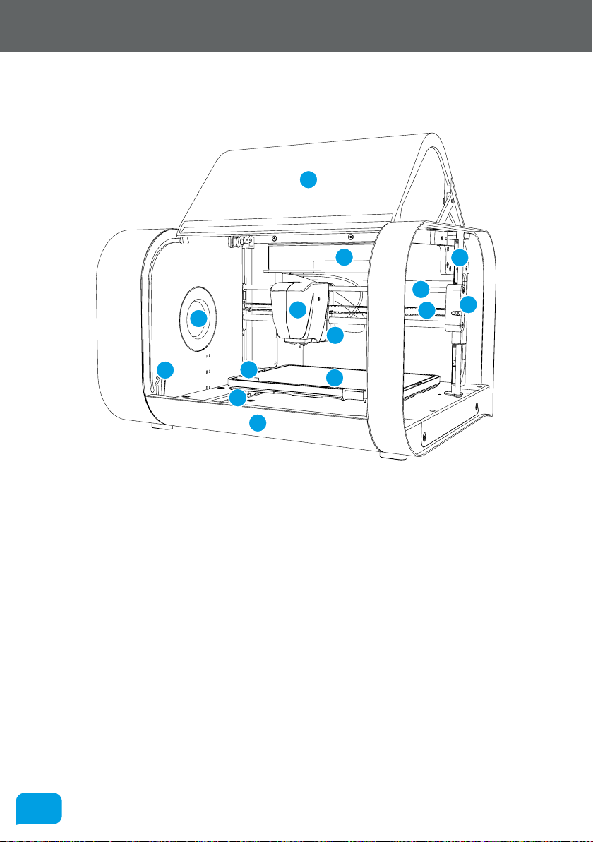
2.5 At A Glance
This section highlights all the major features of Robox®.
12
11
10
13
1
2
9
5
14
4
6
3
7
8
1 Print Head 8 X Axis Belt
2 X Carriage 9 Tip Wipe Blade
3 X Axis Rails 10 Reel Hub Cover
4 Print Bed 11 Door Interlock Latch
5 Y Axis Rail 12 Enclosure Door
6 Z Axis Rail and Drive Screw 13 Internal Ambient Lighting
7 Z Carriage (Right) 14 Front Tray Cover
www.cel-robox.com
2525
2.0 Overview
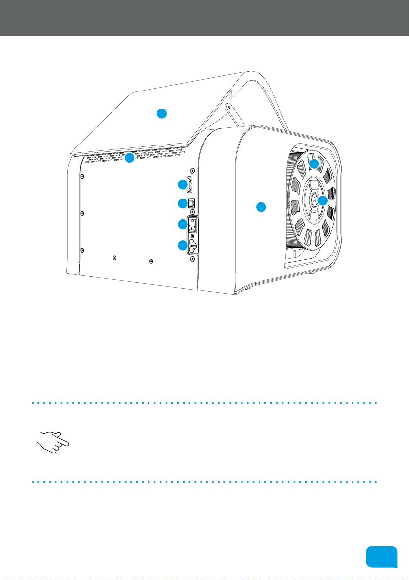
This view shows the rear connections of Robox® and the SmartReel™ location.
8
7
1
2
3
4
9
5
6
1 microSD Card Flash Storage 6 Pause/Resume/Eject Button
2 USB Type B Socket 7 Outlet Vents
3 Power Switch 8 Door
4 C5 ‘Cloverleaf’ Power Inlet 9 Side Cover
5 Robox® SmartReel™
• Although there is a microSD card accessible from the back of Robox®, this
cannot be read by any other machine and is only for use as internal flash
storage - access is provided only for diagnostic/repair purposes.
• Do NOT connect the USB cable until you have completed the installation of
AutoMaker™ - see section 3.3.
www.cel-robox.com

3.0
Getting Started
2727
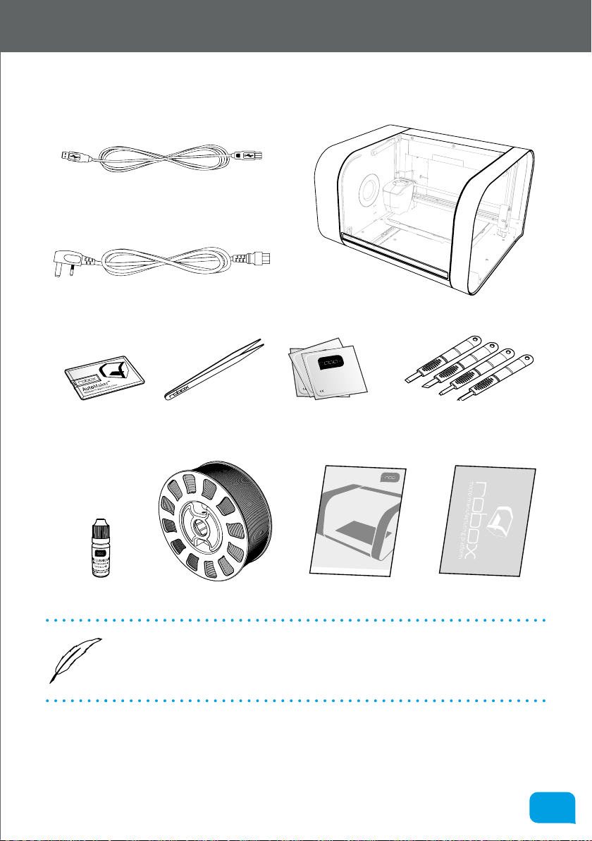
3.1 Package Contents
Check your product package for the following items.
2m USB A-B Cable
3.0 Getting Started
IEC C5 Power Cable
Axis Lubricant
• If any of the above items are damaged or missing, contact your retailer.
• The illustrated items above are for reference only. Actual product
Robox®
BED CLEANING WIPE
BED CLEANING WIPE
70% Isopropyl Alcohol
BED CLEANING WIPE
70% Isopropyl Alcohol
70% Isopropyl Alcohol
NOT FOR MEDICAL USE
NOT FOR MEDICAL USE
NOT FOR MEDICAL USE
0197
0197
0197
Safety
Information
Versi
on
1.0
w
ww.cel-robox.com
SmartReel™
specifications may vary with dierent models.
Safety Guide Warranty Card
Set of 4 Cleanup ToolsUSB Flash Drive Tweezers 10x Bed Wipes
www.cel-robox.com
2828
3.0 Getting Started
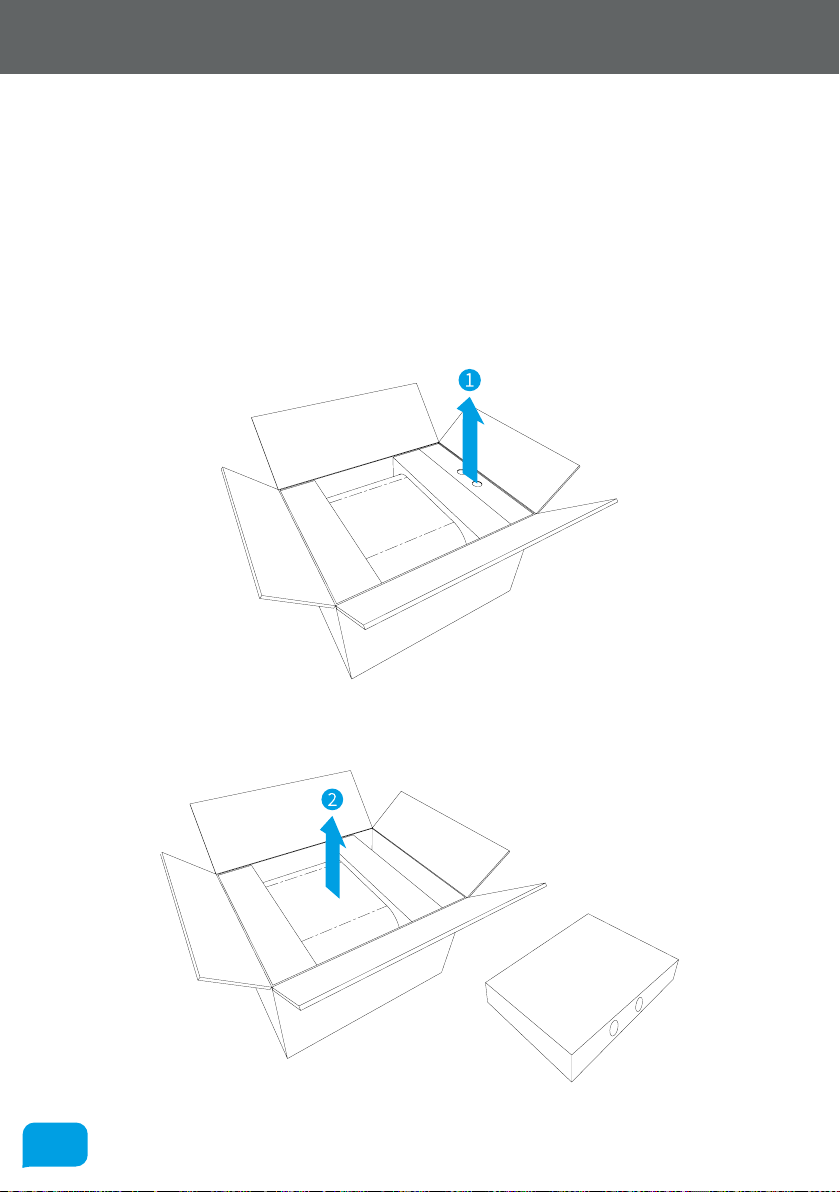
3.2 Unpacking Robox®
This section explains how to safely unpack your new Robox® and get it ready
for production! Your new micro manufacturing platform has been carefully
assembled and packaged at our factory to arrive with you in perfect condition.
Please follow the instructions below carefully to avoid causing any damage.
9. Carefully cut the tape along the top of the box, being careful not to cut too
deep, and open the box.
10. Remove the accessories box from the side by pulling on the plastic handle.
11. Slide your Robox® to the centre of the box and with a firm grip on both pulp
packing trays, li out and place on a stable surface .
www.cel-robox.com
2929
3.0 Getting Started
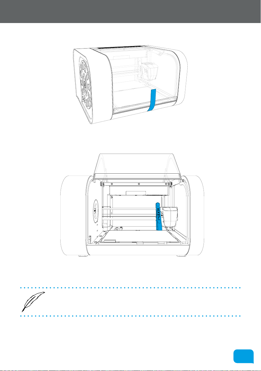
12. Remove the packing tape which is used to secure the door.
13. Next, remove the 3D printed packing clip which is used to secure the
printhead, Z-carriage and bed during shipping.
14. Ensure that the head and bed are free to move before proceeding. You can
move them both by hand to check.
• We recommend that you keep hold of all of your packaging materials
should you need to return any parts to us.
www.cel-robox.com
3030
3.0 Getting Started
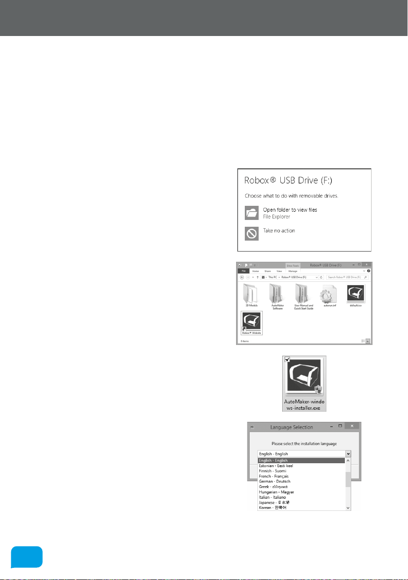
3.3 Soware Installation
This section explains in detail how to install the AutoMaker™ soware package for
controlling your Robox®. The included USB card drive contains this soware and
an electronic version of this document, as well as some sample .stl files for you to
print.
These steps may vary slightly depending on your operating system, all provided
screenshots and instructions are from Windows 8.1 for reference.
1. Plug your included USB drive into an
available USB port (drive letter may vary) choose Open folder to view files:
If this is not displayed, you can access the
drive through My Computer.
2. The contents of the drive will be displayed
in File Explorer as shown (view mode
may vary).
3. Navigate to \AutoMaker Soware\
Windows and run the installer by
double-clicking on the icon - AutoMaker-
windows-installer.exe
4. Select the installation language from the
dropdown menu, and then click OK to
continue.
www.cel-robox.com

3131
5. The installer will start, click Next > to
continue.
6. Please carefully read the Licence
Agreement and select ‘I accept the
agreement’, then select Next > to
continue.
7. Please choose where you would like to
install AutoMaker™ either by typing the
path directly, or by clicking the button.
Click Next > to continue and accept the
path and begin the installation. N.B. To
facilitate future support we recommend
using the default install location.
3.0 Getting Started
8. Choose whether you would like to add
Shortcuts to the Start Menu or Desktop.
Then click Next > and wait as AutoMaker™
is installed to your hard drive.
9. Installation is complete. Tick the checkbox
if you would like to read the ‘Readme’ file
or start AutoMaker™ immediately aer
clicking Finish.
www.cel-robox.com

3232
3.0 Getting Started
3.4 Starting AutoMaker™
This section explains how to start AutoMaker™ on all supported operating
systems.
3.4.1 On Windows
To start AutoMaker™, double click on the icon shown below on your desktop:
It can also be launched using the Start Menu in the normal way - it can be found
under ‘CEL’.
3.4.2 On MacOS
To start AutoMaker™, click the icon which has been added to your dock. It can
also be found under Applications in Finder.
3.4.3 On Linux
To start AutoMaker™, open a terminal window and navigate to the installation
directory (default is “CEL/AutoMaker”) and type “./AutoMaker.run” to start.
www.cel-robox.com

3333
3.0 Getting Started
3.5 Attaching the USB Cable
Robox® comes supplied with a 2 metre USB Type A-Type B cable for connecting
to your PC. Please connect as shown.
• DO NOT connect your Robox® until you have been through the soware
installation steps on the previous page and started AutoMaker™.
3.6 Attaching the Power Cable and Powering On
Connect the supplied AC power lead to Robox® and switch on using the rear
power switch.
2
1
This will install the necessary drivers for connecting your Robox® and could take
a few minutes. When correctly installed and switched on, it should appear in
Device Manager as a COM port called “Robox v1.0 (COM3)” (COM number may
vary). It should also appear on the Status Page of AutoMaker™, along with what
reel and head are installed.
www.cel-robox.com

4.0
Using Robox®

3535
4.0 Using Robox
4.1 Loading Filament
This section explains how to load your chosen 3D printing plastic filament
into Robox® ready to produce your first print! It is designed to be a very simple
process with most functions taking place automatically.
4.1.1 Preparing the Filament
Before attempting to load filament, it is advisable to cut the end cleanly at a rightangle. This will allow the filament to enter the extruder and melt chamber more
easily.
4.1.2 Feeding to the Head
Simply feed the end of the filament into one of the two extruder entrances
located in the bottom-le of the reel storage dock. If only one extruder is installed
in your machine, use the top path marked ‘1’. It is much easier to perform this
operation BEFORE installing the reel into the dock.
Once the filament reaches the extruder, you will hear the motor start; at this point
continue to feed in until you feel the filament has been grabbed. Robox® will
then automatically feed the material all the way to the head.
www.cel-robox.com
3636
4.0 Using Robox
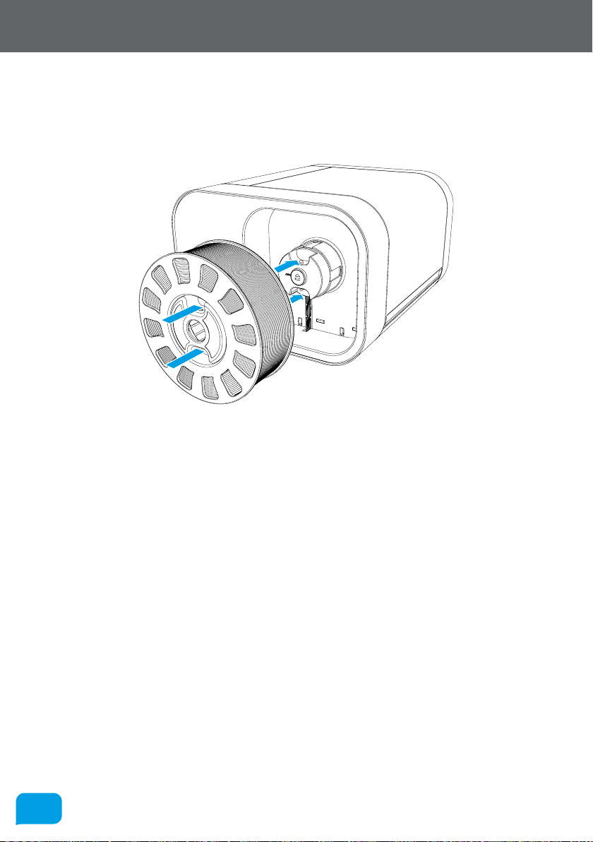
4.1.3 Installing the Reel
Finally, install the SmartReel™ into the dock, you should hear a click when it
is correctly located, and it should appear as a recognised reel in AutoMaker™.
Congratulations! - you’re now ready to print.
www.cel-robox.com

3737
4.0 Using Robox
4.2 Unloading Filament
This section explains how to remove a reel of filament for storage or to change to
a dierent colour/material. This process has also been designed to be as simple
as possible, and can even be undertaken mid-print!
4.2.1 Pause / Resume / Eject Button
There is a button in the centre of the reel when installed which has three
functions - Pause, Resume and Eject. To pause the print, simply press this button
once, and to resume press the button again.
To eject filament, you must hold down this button for 3 seconds, at which point
you should hear the extruder motor start and the filament will start to reel back
onto the spool.
www.cel-robox.com

3838
4.0 Using Robox
4.2.2 Removing The Reel
Once the extruder motor has stopped, your filament has been fully ejected. Press
the two metal buttons on the top and bottom of the reel hub and pull the reel
away from the machine. Coil any extra material onto the reel - the loose end can
easily be held by weaving in and out of the holes in the rim.
1
1
2
4.3 Filament Storage
Most plastics, including ABS and PLA are ‘hygroscopic’ in nature i.e. they absorb
water from the surrounding environment. This oen has desirable eects, for
example in the case of Nylon, higher water content results in higher part strength.
However, when using plastic filament as a feedstock for 3D printing, higher water
content has a negative eect. As the plastic melts in the head, the water content
evaporates and turns into steam. As the molten plastic leaves the nozzle, the
reduction in pressure creates bubbles in the extrudate. This ‘outgassing’ of steam
can ruin the quality of the print, leaving pock marks in the surface finish where
the bubbles have popped.
It is therefore essential to store your filament somewhere very dry when your
Robox® is not in use for any extended period of time. SmartReels are packaged in
an airtight sealable bag with a sachet of silicagel, which should remove any water
from the bag and keep your filament dry. We recommend returning your filament
to its bag aer each print to ensure it stays print fresh!
If you already have ‘wet’ filament, it can be dried using an o-the-shelf dessicant
or dehumidifier - look out for colour indicating silicagel which changes from
orange to green to indicate it has become saturated. It can then be dried in a
conventional oven to ‘recharge’ it - refer to it’s accompanying instructions.
www.cel-robox.com

3939
4.0 Using Robox
Head Change
4.4 The HeadLock™ System
This section explains how to change the head on Robox® allowing you to change
its functionality. The base model comes supplied with the Dual Nozzle, Single
Material head for FFF 3D printing. All future head designs will make use of the
same interface, and the HeadLock™ system has been designed to make head
replacement quick and easy. A microchip in each head also allows AutoMaker™
to automatically identify what head is installed, and set itself up appropriately.
4.4.1 Removing a Head
To remove the head, click the ‘Head Change’ button in AutoMaker™ and you will
see the head move into position to allow easy access to the locking screw.
Turn o your Robox® using the power switch on the back or at the wall
outlet.
This screw is located behind the head on the back of the X Carriage and is used
to firmly constrain and fix the head to the carriage. Reach over the top of the
head and rotate this screw counterclockwise to unlock, as shown in the diagram
below:
Continue to rotate the locking wheel until you feel it turning freely.
www.cel-robox.com

4040
4.0 Using Robox
Once unscrewed, pull down the head as shown in the diagram below - you will
hear a ‘snap’ as the head disconnects.
4.4.2 Installing a Head
To install a new head into Robox®, the process is essentially the same in reverse.
First, push the bottom of the head into the carriage until you hear/feel a ‘snap’
- this signifies the head is correctly aligned and located, then simply tighten the
locking wheel until fully tight. You should see the head recognised in AutoMaker™
when you switch the power back on.
1
2
1
2
www.cel-robox.com

4141
4.0 Using Robox
4.5 Removing the Bed
To remove the PEI bed from your Robox®, simply slide the handle on the front of
the bed (highlighted in blue) to the le to release. Then li up the front edge of
the board using the finger recess (shown by the hand) and slide the bed towards
you.
4.6 Installing the Bed
To re-install the bed, simply slide the sheet towards the back of the tray, ensuring
the tabs are aligned beneath the 4 metal clips on the sides, and then push all the
way to the back until it slides under the rear clip and stops. Then simply slide the
handle on the front to the right, securing it in position.
www.cel-robox.com

5.0
AutoMaker Soware

4343
5.0 AutoMaker Soware
5.1 User Interface
This section outlines the major elements which make up the AutoMaker™ user
interface. There are basically 3 separate screens - Status, Layout and Settings.
• Status Screen - This page displays the current status of the selected printer. It
shows what it’s doing, what filament and head are installed, as well as extra
information on temperatures etc.
• Layout Screen - This page is used for laying out the 3D models of objects
you’d like to print. They can be moved, scaled, duplicated and rotated using
simple controls.
• Settings Screen - This page allows you to choose print settings, for example
materials, quality/speed, fill density and support.
The soware is designed to be as simple to use as possible, so we have removed
a lot of the more advanced settings from plain sight, but don’t worry there’s
plenty of room for you tinkerers too!
The diagram below shows the main screen elements of AutoMaker™.
3
2
1
1 Side Bar 4 Toolbar
2 Advanced Tray 5 Program Window
3 Tab Bar
www.cel-robox.com
5
4

4444
5.0 AutoMaker Soware
5.2 Print Workflow
• AutoMaker™ is continually being improved - please check our website for an
updated version of the user manual if you require further information.
www.cel-robox.com

4545
5.0 AutoMaker Soware
5.3 Status Screen
This section explains the status screen in more detail.
4 5
1
6
2
9
3
7 8 10
1 Connected Printers 6 Current Printer Status
2 Installed Filament 7 Unlock Door
3 Temperature Display 8 Eject Filament
4 Projects Tabs 9 Display Advanced Settings
5 Preferences 10 Go To Settings Screen
5.3.1 Connected Printers
This area of the screen displays the status of all printers which are currently
attached to your PC.
Ready
Printing
Paused
Notification
Error
www.cel-robox.com

4646
5.0 AutoMaker Soware
110m / 372g remaining
1: PLA
50m / 125g remaining
1: ABS
Not Available
1: ERROR
Each Robox® connected to AutoMaker™ has its own icon which displays the
name and current status of the printer, as well as an indicator which shows the
progress of the current print (if available).
The status icons can be summarised as follows:
• Ready - When Robox® is available and ready to print.
• Printing - When Robox® is currently printing an object.
• Paused - When Robox® has been paused during a print.
• Notification - When a message is available in the printer status.
• Error - When Robox® has a problem which must be resolved before
continuing.
5.3.2 Installed Filament
AutoMaker™ will automatically recognise the material installed on the reel using
data stored on a chip inside the reel. Depending on the type of filament on the
reel, they are displayed in dierent ways, as shown below:
Chroma Green
Generic/Custom 1
Unrecognised Reel
Some of this information is also displayed in the ‘Current Printer Status’ area of
the screen, where the reel is shown installed on the le of the printer.
5.3.3 Temperature Display
This area of screen displays a historical graph of the bed, nozzle(s) and ambient
temperature over time.
™
Robox® SmartReel™
This will be displayed as a reel symbol.
Generic/Custom Material
This will be displayed as a gear symbol.
Unrecognised/Unformatted Reel
This will be displayed as a crossed circle.
www.cel-robox.com
4747
5.0 AutoMaker Soware
WARNING!
Hot Surfaces
5.3.4 Projects Tabs
This part of the screen shows the currently available print jobs. On starting,
AutoMaker™ will create an empty project and load any projects which weren’t
closed on the previous run. Other functions are summarised below:
- Creates a new project file
- Displays the context menu explained below
Rename
Export
Email
Upload
- Change the name of the project
- Export the selected project as a .robox file
- Email the selected project
- Upload the selected project to your Robox® Account.
5.3.5 Current Printer Status
This part of the display provides an overview of the selected Robox®. It shows you
what filament, bed and head is installed and also displays warning and status
messages.
For example when installing a new filament reel, you will see the reel appear on
the status screen. As the bed and head are heating up, you will see a warning
message appear once the temperature exceeds 60°C (140°F):
www.cel-robox.com

4848
5.0 AutoMaker Soware
5.3.6 Advanced Settings
This part of the screen allows you to perform more advanced functions relating
to the overall printer - print job settings are accessed from the Settings Screen see section 5.5. Its functions are summarised below:
1
2 3
4 5 6 7
1 GCode Console Output 5 Head Programming
2 GCode Text Entry 6 Calibration and Maintenance
3 Send GCode to Robox® 7 Diagnostics
4 SmartReel™ Programming
• GCode Console
This console allows you to manually send GCode commands to Robox® over
the USB cable. Simply type the command in the text entry box (2) and then
click Send GCode (3). A list of all GCode commands applicable to Robox®
can be found in the Supplementary Information section at the back of this
manual - section 8.1.
www.cel-robox.com

4949
5.0 AutoMaker Soware
5.3.7 Advanced Settings - SmartReel™ Programming
This page is for writing custom material parameters to a Robox® SmartReel™.
Simply choose which reel to apply the settings to, choose a material from the list
- custom or oicial, then click the Program Reel button.
1 2
3
4
1 Apply to Reel Hub 1 3 Material Selection
2 Apply to Reel Hub 2 4 Program Reel
5.3.8 Advanced Settings - Head Programming
This page is for programming the print head with the correct settings based on
CEL supplied defaults. Simply click the type of head you have, and click Reset
to Defaults. It also displays the unique serial number for your printhead which is
useful when contacting CEL support.
3
1 Select Head Type 3 Reset Head Defaults
2 Head Serial Display
www.cel-robox.com
1
2

5050
5.0 AutoMaker Soware
5.3.9 Advanced Settings - Calibration and Maintenance
This page is for executing a wide range of ‘macros’ (small GCode programs that
execute sequentially) and for access to machine calibration - see section 7.1.
1 2
3 4
5 6
7 8
9 10
11 12
13
14
15
1 Send SD GCode 9 Y Test Routine
2 Stream GCode USB 10 Speed Test
3 Clean Fine Nozzle 11 Level X Gantry
4 Clean Fill Nozzle 12 Level Y Axis
5 Purge Material 13 Calibrate Nozzle Opening
6 Eject Stuck Material 14 Calibrate Nozzle Height
7 X Test Routine 15 Load Firmware
8 Z Test Routine
• Send GCode Manually
AutoMaker™ can be used to send GCode manually to Robox® by one of two
methods - SD (1) or USB (2) i.e. sending data to the onboard SD flash storage
before executing, or transmitting each command one by one over the USB
www.cel-robox.com

5151
5.0 AutoMaker Soware
cable as they are executed.
• Clean Nozzles
This executes a short GCode ‘macro’ that makes use of the Tip Wipe blade
at the front of the bed, and as such should only be executed when the bed is
clear of objects. You can choose to clean either the fill or the fine nozzle.
• Purge Material
This executes the purge routine, which is used when changing between two
dissimilar materials - see section 7.2.1.
• Eject Stuck Material
If you are having diiculty ejecting your filament, this routine may be able to
rectify the problem. If you are still unsucessful, please contact CEL support.
• Test Routines
These routines are for checking the performance of all the motor axes - X,
Y and Z. Speed test gradually ramps up the speed as the test progresses,
allowing you to isolate any issues with motion.
• Level X Gantry
This button executes the automatic bed levelling algorithm. By probing the
bed in multiple locations, Robox® is able to determine the level of the bed
and independently adjust the Z motors to ensure the X gantry is parallel.
• Level Y Axis
This is currently an experimental feature which can further improve
the quality of bed levelling. Rather than just levelling the gantry, it can
continuously adjust the Z height as the bed moves forwards and backwards,
ensuring the nozzle is always the same distance from the bed.
• Calibrate Nozzle Opening
This routine is used to calibrate the point at which the needle valves in the
head operate - see section 7.1.1.
• Calibrate Nozzle Height
This routine is used to calibrate the nozzle li height - see section 7.1.2.
• Load Firmware
You shouldn’t require this function, unless directed by CEL support - it is used
for manually flashing the onboard firmware.
www.cel-robox.com

5252
5.0 AutoMaker Soware
5.3.10 Advanced Settings - Diagnostics
This page is really only intended for diagnosing possible faults with your Robox®.
It displays the serial numbers of the printer and the head which will be required
when contacting CEL support. It also displays the state of all of the microswitches
in the printer so that you can verify they are functioning correctly.
1
2
3
1 Printer Serial Number 3 Switch Diagnostics
2 Head Serial Number
• Switch Diagnostics
When any of these switches are triggered on the hardware, they will light up
on screen, so you can verify if they are working. There are lights for all limit
switches, the door open switch (located in the top le of the build chamber,
where it interacts with the door arm), the reel eject button, and the feedback
from both extruders. Each extruder has two outputs - ‘loaded’ is the extruder
output switch which detects when filament leaves the extruder, and index is
the output from the indexing wheel which measures the passage of filament
- you will see it toggle on and o as you move filament back and forth.
www.cel-robox.com

5353
5.0 AutoMaker Soware
5.4 Layout Screen
This section explains how to lay out objects on the bed and prepare for printing.
1
12
13
1
2 3 4 5 6 7 8 9
1 Return to Status Screen 8 Auto Layout All Objects
2 Undo Previous Change 9 Group/Ungroup Objects
3 Redo Change 10 Preferences
4 Add New Model 11 Go To Settings Screen
5 Remove Selected Model 12 Model Display
6 Duplicate Selected Model 13 Advanced Settings
10
11
7 Lay Model Flat
• Preferences
This displays the AutoMaker™ preferences page - see section 5.6.
• Model Display
This displays a preview of the selected print job, showing the print bed and
any objects you have added, arranged as they will be printed. You can rotate
the view by clicking the right mouse button and dragging , pan around by
holding the <Alt> key and dragging with the right mouse, and zoom by rolling
the mouse wheel.
www.cel-robox.com

5454
5.0 AutoMaker Soware
Undo
Redo
Add Model
Remove Model
Duplicate
Rotate View (click and drag)
+
Pan View (click and drag)
Zoom (scroll wheel)
Select and manipulate models
+
Select multiple models
5.4.1 Arranging Items on the Bed
This section explains the layout function of the soware which allows you to
arrange your 3D models on the bed ready for printing. It is designed to be very
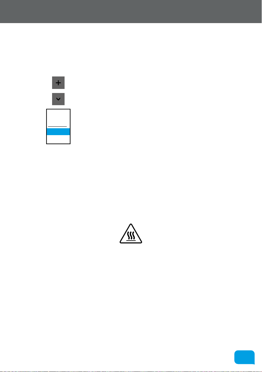
simple, requiring only the following buttons:
Step back through the history of layout operations
you have completed i.e. undo the last command you
executed.
Step forward through the history of layout operations.
This is used to add a new model (.stl/.obj) to the
build plate - clicking it reveals a file browser dialog to
choose your model from the local filesystem.
This is used to remove the selected model from the
build plate.
This is used to duplicate the currently selected item
and place it on the build plate.
www.cel-robox.com

5555
5.0 AutoMaker Soware
Lay Flat
Auto Layout
Group
This is for reorienting your model to the build plate.
Click the button, and then select a surface on the
model that you would like to lay flat to the bed.
This automatically arranges all models on the bed
with suicient clearance between them and no
interference.
This used to collect multiple objects together into one
selection. When a group is selected, this button will
toggle to ‘Ungroup’.
• AutoMaker™ is continually being improved - please check our website for an
updated version of the user manual if you require further information.
www.cel-robox.com

5656
5.0 AutoMaker Soware
5.5 Settings Screen
This section explains the basic settings page of the soware which allows you to
choose quality options and materials for your print.
6
1
3
2
4 5
7
1 Filament Settings 5 Start the production (Make!)
2 Print Settings 6 Return to Status Screen
3 Advanced Settings 7 Model Display
4 Return to Layout Screen
5.5.1 Starting Production
To start a print, simply choose a quality setting from the Print Settings box (2),
verify that your material has been selected in the Filament Settings box (1), and
press Make! (5).
AutoMaker™ will then begin to slice your 3D model and transfer to your Robox®
ready for printing. Due to the unstable nature of printing ‘by wire’ - sending data
over USB during a print, Robox® incorporates onboard flash storage for storing
print jobs once production has started. This means that when the print job
has been fully transferred, you can disconnect from the USB, and Robox® will
continue to print unattached.
www.cel-robox.com

5757
5.0 AutoMaker Soware
5.5.2 Filament Settings
This part of the screen displays what colour and type of filament is currently
installed in the machine and allows you to choose and create custom material
profiles. It will also show you how much material is remaining on each reel. A
brief description of its functions is shown below:
3
1
4
2
6
5
1 Extruder 1 Reel 4 Material Colour
2 Extruder 2 Reel 5 Filament Remaining
3 Material Type 6 Filament Type
• Material Type
This displays the material on the reel of filament which is currently
installed in Robox® - 1 for the primary reel and 2 for the secondary. A whole
range of dierent materials is available to purchase on SmartReels from
www.cel-robox.com.
• Material Colour
This displays the colour of the reel which is installed - click the dropdown
menu to define a custom filament - see section 5.5.4.
• Filament Remaining
This displays the amount of filament le on the reel in metres and grams.
• Filament Type
This icon denotes the type of reel installed in Robox® - SmartReel™, Custom,
Unkown or Unrecognised - see section 5.3.2.
www.cel-robox.com

5858
5.0 AutoMaker Soware
5.5.3 Print Settings
This allows you to adjust the quality and print profile for production.
1
2
3
4
5
6
1 Quality Setting 4 Fill Density
2 Custom Print Profile 5 Support Material Setting
3 Profile Summary 6 Brim Width
• Quality Setting
This allows you to select a basic quality setting from the list of options - Dra,
Normal or Fine. The final option - Custom allows you to create a new profile
or to select from a previously created one. To create a new profile, click the
selection box and choose Create New... - this will expand the Advanced Tray
to the right (see section 5.5.5).
• Profile Summary
This displays a brief summary of the currently selected print settings. The
information available is as follows:
• Layer Height in microns (µm).
• Perimeters use - which nozzle is used to print the outside surface of the
object.
• Infills use - which nozzle is used to print the inside fill of the object.
www.cel-robox.com

5959
5.0 AutoMaker Soware
90% Fill 80% Fill 70% Fill 60% Fill 50% Fill 40% Fill 30% Fill
• Fill Density
This setting allows you to choose how ‘solid’ you would like the finished
object to be. The fill pattern can also be changed using a custom profile - see
section 5.5.6.
• Support Material
This switch toggles the printing of support material. If you are printing a part
with large overhangs, you may wish to print structures at the same time
to support the object. Support settings (e.g. density and type) can also be
changed using a custom profile - see section 5.5.8.
• Brim Width
‘Brim’ is a term applied to FFF (Fused Filament Fabrication) which describes
a large flat area which is printed around the part to help with bed adhesion
and warping. It can be easily trimmed o aer printing, but may greatly
increase the success rate of prints with a small surface area at the base. This
number specifies the number of loops (and therefore the width) of the brim.
www.cel-robox.com

6060
5.0 AutoMaker Soware
5.5.4 Advanced Settings - Material
This section explains the advanced page, and it’s associated functions and
options.
1
2
3
4
5
6
7
8
9
10
11
12
1 Material Name 7 Bed Temperature
2 Material Type 8 Bed Temperature (1
st
Layer)
3 Material Colour 9 Nozzle Temperature
4 Filament Diameter 10 Nozzle Temperature (1
st
Layer)
5 Filament Multiplier 11 Ambient Temperature
6 Feed Rate Multiplier 12 Help Text
www.cel-robox.com

6161
5.0 AutoMaker Soware
• Material Name
This field can be used to name the material profile - this will be displayed on
the Status page when the reel is installed in the dock.
• Material Type
Pick the material type here from the list of available options, or type the
name of the material yourself.
• Material Colour
Pick the material colour here, or choose custom to define your own colour.
• Filament Diameter (mm)
Enter the diameter of your filament in mm - it is recommended to use digital
calipers / micrometer to obtain an accurate value for this field.
• Filament Multiplier
This value is used to compensate for the ‘squishyness’ of your material. As
filament passes through the extruder, it can be compressed by the feed
wheels causing to change shape slightly. This can aect the amount of
material that is fed to the head - the harder the material, the closer this value
should be to 1.
• Feed Rate Multiplier
This multiplier allows you to finely tune the extrusion rate of the material - it
can be adjusted during a print to obtain the optimum extrudate profile.
Increasing the value above 1 will cause more material to be extruded and
vice versa - 2 would be equivalent to 200% material flow. It varies the amount
of plastic proportionally and should be changed in very small steps (e.g. +/-
0.05) as the eects are very visible.
• Bed Temperature (°C)
This value sets the temperature of the print bed surface during a print. A
heated bed will help to reduce warping and improve adhesion of a wide
range of materials. ABS requires a bed temperature of approximately 110°C
for good adhesion, whereas PLA only requires 60-80°C.
• Bed Temperature (1
This value sets the temperature of the print bed surface when printing the
very first layer of the object. This value is oen set higher to ensure good
adhesion when starting a print, however the temperature can be lower for
the remainder of the print, or it may cause the object to ‘sag’ at its base.
st
Layer) (°C)
www.cel-robox.com

6262
5.0 AutoMaker Soware
• Nozzle Temperature (°C)
This value sets the temperature of the nozzle used for printing the material.
Dierent thermoplastics require dierent nozzle temperatures due to their
diering melting points (or more accurately, glass transition temperatures).
For example, most ABS requires a nozzle temperature of 240°C, whereas PLA
only requires 200°C to print successfully.
• Nozzle Temperature (1
This value sets the temperature of the nozzle when printing the very first layer
of the object. This value is oen set higher to ensure good adhesion when
starting a print, however the temperature can be lower for the remainder of
the print.
• Ambient Temperature (°C)
This value sets the temperature of the enclosed build area. By maintaining
the temperature of the environment, it is possible to keep the printed object
warm, reducing its tendency to shrink and warp. The best results will be
obtained by maintaining the temperature of the object until the end of
the print when the whole object can be cooled simultaneously. Warp is
introduced when the part is cooling unevenly, with areas that are shrinking
exerting forces on areas that are still warm and so.
st
Layer) (°C)
• Help Text
This box displays a brief explanation of the setting which is highlighted
(changes on mouseover).
www.cel-robox.com

6363
5.0 AutoMaker Soware
5.5.5 Advanced Settings - Print Profile
This section explains the advanced page, and it’s associated functions and
options:
3 41 52
1 Advanced Extrusion Settings 4 Advanced Speed Settings
2 Advanced Nozzle Settings 5 Advanced Cooling Settings
3 Advanced Support Settings
• Advanced Extrusion Settings
This allows you to adjust advanced printing profile parameters relevant to
extrusion e.g. layer height, fill density and fill pattern - see section 5.5.6.
• Advanced Nozzle Settings
This allows you to adjust advanced printing profile parameters relevant to
both nozzles and needle valve control - see section 5.5.7.
• Advanced Support Settings
This allows you to adjust advanced printing profile parameters relevant to
automatic support material generation e.g. angle threshold and support
pattern and density - see section 5.5.8.
• Advanced Speed Settings
This allows you to adjust advanced printing profile parameters relevant
to print speed e.g. perimeter speed, infill speed and bridging speed - see
section 5.5.9.
• Advanced Cooling Settings
This allows you to adjust advanced printing profile parameters relevant to
cooling e.g. fan speeds and minimum time per layer - see section 5.5.10.
www.cel-robox.com

6464
5.0 AutoMaker Soware
5.5.6 Advanced Settings - Extrusion
These settings allow you to adjust all the parameters which aect the
extrusion of plastic and generally relate to print quality and speed. By tuning
these values, users can control the appearance, strength and surface finish of
objects, as well as dramatically aecting print speed by varying layer height,
fill pattern, density and perimeters.
1
2
3
4
5
6
7
8
1 Layer Height 5 Top and Bottom Layers
2 Fill Density 6 Number of Perimeters
3 Fill Pattern 7 Brim Width
4 Infill Every ... Layers 8 Help Text
www.cel-robox.com

6565
5.0 AutoMaker Soware
Chords
Spiral
• Layer Height (mm)
This setting defines the layer height (essentially the print resolution) of
the printed object. Users can select from any value between 20-400µm,
however this setting will dramatically aect print time as shown in the below
illustration:
Print
Representation
(1.6mm Total Height)
Layer Height 400µm 200µm 40µm 20µm
Number of Layers 4 8 40 80
Total Print Time 8 mins 16 mins 1hr 20mins 2hrs 40mins
Also apparent from this diagram is the improved surface finish that will
be acheived as layer height is decreased - notice the reduction in the
appearance of the ‘stair stepping’ eect.
• Fill Density (%)
This setting changes the amount of material which is used to fill the interior
of the object. 100% signifies a completely solid object, and 0% is hollow.
• Fill Pattern
This setting is used to change the pattern of the extrusion used to fill the
interior of the part. There are 7 dierent options to choose from:
Line Rectilinear Honeycomb Concentric Archimedean
Octagram
• Infill Every n Layers
This setting forces Robox® to add a solid infill layer every n layers. To disable
this option, enter 0.
• Top and Bottom Layers
This setting specifies how many solid layers will be used to complete the
top and bottom of the object. You may need to increase this setting if you
are printing an object with a top or bottom surface which tends towards
horizontal to avoid gaps in the outer surface.
www.cel-robox.com
Hilbert Curve

6666
5.0 AutoMaker Soware
• Number of Perimeters
This setting specifies how many outside walls are produced to complete the
exterior surface of the part. The more perimeters, the thicker the part walls.
• Brim Width
This is explained in ‘Print Settings’ - see section 5.5.3.
• Help Text
This box displays a brief explanation of the setting which is highlighted
(changes on mouseover).
www.cel-robox.com

6767
5.0 AutoMaker Soware
5.5.7 Advanced Settings - Nozzles
These settings allow you to adjust all the parameters which aect the
operation of the nozzles and needle valves. By tuning these values, users
can control the appearance of start/stop points and surface finish, as well as
dramatically aecting print speed through the use of the larger fill nozzle.
1
2
3
4
5
6
7
8
9
10
11
12
1 Perimeter Nozzle Selection 7 Ejection Volume
2 Fill Nozzle Selection 8 Wipe Volume
3 Support Nozzle Selection 9 Partial Open Value
4 Support Interface Nozzle 10 Retract Length
5 Fine Nozzle Settings (0.3mm) 11 Retract/Unretract Speed
6 Fill Nozzle Settings (0.8mm) 12 Help Text
www.cel-robox.com

6868
5.0 AutoMaker Soware
• Perimeter Nozzle Selection
This setting allows you to choose which nozzle is used to print the exterior
surfaces (perimeters) of the part - choose from 0.3mm (fine nozzle) or 0.8mm
(fill nozzle).
• Fill Nozzle Selection
This setting allows you to choose which nozzle is used to print the internal
filling of the part - choose from 0.3mm (fine nozzle) or 0.8mm (fill nozzle).
• Support Nozzle Selection
This setting allows you to choose which nozzle is used to print support
material around the part - choose from 0.3mm (fine nozzle) or 0.8mm (fill
nozzle).
• Support Interface Nozzle Selection
This setting allows you to choose which nozzle is used to print support
interface layers i.e. those between the build and support material - choose
from 0.3mm (fine nozzle) or 0.8mm (fill nozzle).
• Fine Nozzle Settings (0.3mm)
This switches the settings below to apply to the fine nozzle (0.3mm).
• Fill Nozzle Settings (0.8mm)
This switches the settings below to apply to the fill nozzle (0.8mm).
• Ejection Volume (mm³)
This parameter specifies the volume of material that is ejected as the needle
valve closes. The needle itself has a volume, and therefore displaces its
equivalent volume of plastic as the valve closes.
• Wipe Volume (mm³)
This parameter specifies how much material is le inside the tip of the nozzle
once the needle valve has closed. The ‘wipe’ is used to drag this last bit of
material over already printed material to fully drain the nozzle.
• Partial Open Value
This value can be used to specify a smaller needle movement as a ratio i.e. a
value of 0.5 will cause the needle valve to only open halfway.
www.cel-robox.com

6969
5.0 AutoMaker Soware
• Retract Length (mm)
This value specifies the distance the filament is ‘pulled back’ (retracted) at the
end of an extrusion path. This is used to release pressure before the needle
valve begins to close.
• Retract/Unretract Speed (mm/s)
This value specifies the speed that the filament is ‘pulled back’ (retracted) at
the end of an extrusion path and also pushed back in (unretracted) at the
start of the next.
• Help Text
This box displays a brief explanation of the setting which is highlighted
(changes on mouseover).
www.cel-robox.com

7070
5.0 AutoMaker Soware
5.5.8 Advanced Settings - Support
This settings page allows you to adjust all the parameters which aect the
automatic generation of support material. Support material is required
where objects are being built in mid-air due to an overhang.
1
2
3
4
5
6
7
1 Generate Support Material 5 Pattern Spacing
2 Overhang Threshold 6 Pattern Angle
3 Force Support for First ... Layers 7 Help Text
4 Support Pattern
• Generate Support Material
This turns automatic support material generation on and o.
• Overhang Threshold ( ° )
This angle specifies the angular size of an overhang over which support
material is generated. Setting this value to ‘0’ tells AutoMaker to determine
this value automatically.
• Force Support for First ... Layers
This forces AutoMaker™ to generate support material for the first n layers
regardless of the overhang threshold setting.
www.cel-robox.com

7171
5.0 AutoMaker Soware
RectilinearRectilinear Grid Honeycomb Pillars
• Support Pattern
This option allows you to set the pattern used to generate the support
material - with some options requiring less material, giving faster print times.
• Pattern Spacing (mm)
This specifies the spacing in millimetres between support extrusions i.e. the
density of the support material.
• Pattern Angle ( ° )
This option allows the direction of the support lines to be rotated in the XY
plane.
• Help Text
This box displays a brief explanation of the setting which is highlighted
(changes on mouseover).
www.cel-robox.com

7272
5.0 AutoMaker Soware
5.5.9 Advanced Settings - Speed
This settings page allows you to adjust all the parameters which aect the
speed of printing. There are individual settings for various parts of the print
including perimeters, bridges, and infill. By tuning these values, users can
control the appearance of printed objects and optimise speed vs. quality.
1
2
3
4
5
6
7
8
9
10
1 Perimeter Print Speed 6 Top Solid Infill Speed
2 Small Perimeter Print Speed 7 Support Material Speed
3 External Perimeter Speed 8 Bridges Print Speed
4 Infill Speed 9 Gap Fill Print Speed
5 Solid Infill Speed 10 Help Text
www.cel-robox.com

7373
5.0 AutoMaker Soware
• Perimeter Print Speed (mm/s)
This parameter sets the speed at which perimeters (the walls of the object)
are printed in millimetres per second.
• Small Perimeter Print Speed (mm/s)
This parameter sets the speed at which small perimeters (meant for holes,
islands and fine details) are printed in millimetres per second. A slower speed
than ‘Perimeter Print Speed’ is recommended for improved quality of small
details.
• External Perimeter Print Speed (mm/s)
This parameter sets the speed at which external perimeters (the outside
surface of the object) are printed in millimetres per second.
• Infill Print Speed (mm/s)
This parameter sets the speed at which infill (the internal filling of the object)
is printed in millimetres per second. This value should be as fast as you can
go without compromising the integrity of the fill structure. Faster extrusions
can break and result in weak spots of the object.
• Solid Infill Print Speed (mm/s)
This parameter sets the speed at which solid infill (the bottom of the object
and any other solid layers) are printed in millimetres per second.
• Top Solid Infill Speed (mm/s)
This parameter sets the speed at which top solid infill (the top surface of the
object) is printed in millimetres per second. This is usually slower to allow
time for the extrusion to cleanly cover the previous top layers and result in a
tidy top surface. The last few layers should have bridged the infill structure
nicely, preparing the way for a neat finish.
• Support Material Print Speed (mm/s)
This parameter sets the speed at which support material is printed in
millimetres per second. This value should be as fast as you can go without
compromising the integrity of the support.
www.cel-robox.com

7474
5.0 AutoMaker Soware
• Bridges Print Speed (mm/s)
This parameter sets the speed at which bridges (unsupported layers between
two existing surfaces) are printed in millimetres per second. The ability to
span unsupported areas depends on the material and cooling. Going too
slow will result in sagging, too fast will result in broken strands. Generally
bridging runs slower than perimeters.
• Gap Fill Print Speed (mm/s)
This parameter sets the speed at which small gaps are printed in millimetres
per second. Filling in small gaps results in the head quickly oscillating and
the resulting shaking and resonance could have a detrimental aect on the
print. A smaller value here can guard against this. A setting of zero disables
gap filling completely.
• Help Text
This box displays a brief explanation of the setting which is highlighted
(changes on mouseover).
www.cel-robox.com
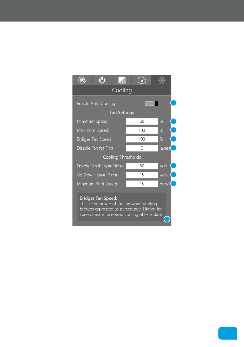
7575
5.0 AutoMaker Soware
5.5.10 Advanced Settings - Cooling
This settings page allows you to adjust all the parameters which aect
automatic cooling of the part as it prints. Layers must be cooled suiciently
before another layer is applied to prevent dimensional inaccuracy and
‘squishy’ small layers.
1
2
3
4
5
6
7
8
9
1 Enable Automatic Cooling 6 Enable Fan if Layer Time <
2 Minimum Fan Speed (%) 7 Go Slow if Layer Time <
3 Maximum Fan Speed (%) 8 Minimum Print Speed
4 Bridges Fan Speed (%) 9 Help Text
5 Disable Fan for First ... Layers
www.cel-robox.com

7676
5.0 AutoMaker Soware
• Enable Automatic Cooling
This setting is used to enable or disable automatic cooling for 3D prints.
AutoMaker™ uses one of two methods to control cooling - it can either
increase the fan speed or slow down the time to print a layer. The choice of
which method is used is controlled by ‘Enable Fan if Layer Time <’ and ‘Go
Slow if Layer Time <’.
• Minimum Fan Speed (%)
This sets the minimum fan head speed as a percentage of full power.
• Maximum Fan Speed (%)
This sets the maximum fan head speed as a percentage of full power.
• Bridges Fan Speed (%)
This sets the fan speed which is used when printing bridges as a percentage
of full power.
• Disable Fan for First n Layers
This disables the head fan when printing the first n layers, this can help with
adhering the first layer to the bed. It is recommended to leave it o for the
first 1 or 2 layers.
• Enable Fan if Layer Time < (seconds)
This will increase the fan speed to maximum if the layer time takes less than
the specified value in seconds.
• Go Slow if Layer Time < (seconds)
This will slow down the print speed if the layer time takes less than the
specified value in seconds.
• Minimum Print Speed (mm/s)
This setting is a lower limit on how slowly a layer can be printed in
millimetres per second.
• Help Text
This box displays a brief explanation of the setting which is highlighted
(changes on mouseover).
www.cel-robox.com

7777
5.0 AutoMaker Soware
www.cel-robox.com

6.0
Finishing Parts
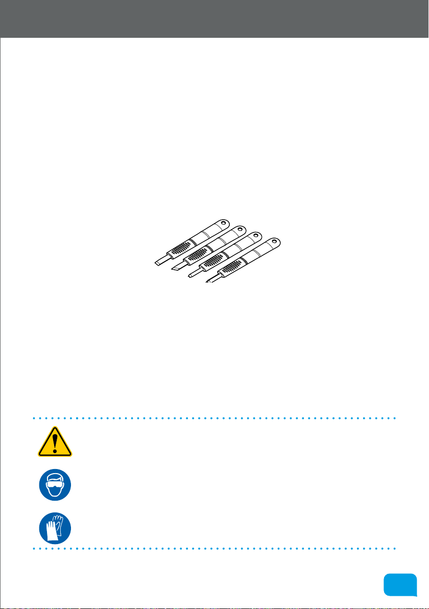
7979
6.0 Finishing Parts
6.1 Removing Breakaway Support Material
Breakaway Support Material is produced using the same material as the desired
part, and therefore Robox® only requires a single material head and one reel
installed. A lattice of material is extruded at the same time as the rest of the part
which is used to ‘prop up’ the printing of unsupported areas (overhangs, bridges
etc.).
Once your object has finished printing, you will need to remove the support
material to reveal the finished part. There are many ways to acheive this, but it
usually requires a combination of brute force and delicate trimming. To help you,
we’ve provided a set of 4 cleanup tools in the accessories box:
There are a range of shapes which should be very helpful when cleaning up small
blemishes on the surface of the part and for cutting away support in diicult to
reach areas.
Some material can easily be broken away from the part, or a pair of needlenose pliers can be useful for crushing/breaking support and then used to pull
the material away. It can be quite a frustrating task, but you will soon discover
methods that work, and those that don’t - once you’ve found a good one it’s
great to see a perfect model emerge from a lump of (seemingly) random plastic.
• WARNING! The set of cleanup tools are very sharp - please take extreme
caution when using them and always cut away from your body. Not
suitable for use by children except under adult supervision.
• WEAR GLASSES Always use safety glasses/goggles when removing support
material, especially PLA as the fragments can be very sharp and could
damage the eyes.
• WEAR GLOVES Always wear gloves when removing support material as the
tools and removed material can be very sharp.
www.cel-robox.com

8080
6.0 Finishing Parts
6.2 Removing Soluble Support Material
If your Robox® has a dual material head and second reel holder (RBX01-DM) then
you can make use of Soluble Support Material for supporting your models. Your
part is le with no visible blemishes and a smooth surface. The larger areas can
be removed by hand to speed up the process, but it is designed to be a largely
hands-o process. There are currently 3 possible material choices:
6.2.1 Polyvinyl Alcohol (PVOH)
This is a water soluble support material which is compatible with PLA and ABS
as a build material. It can be dissolved in cold water, but the process can be
accelerated using ultrasonic vibration and/or slightly elevated temperature.
6.2.2 High Impact Polystyrene (HIPS)
This material is only for use with ABS build material. It can be dissolved in
Limonene, which will dissolve the support but leave the ABS intact. The
dissolving process can be accelerated using ultrasonic vibration and/or slightly
elevated temperature.
6.2.3 Polylactic Acid (PLA)
PLA can be used as a support material for ABS parts - it is soened in hot water,
allowing for manual removal or it can be dissolved using a hot caustic soda
solution and accelerated using ultrasonic vibration.
www.cel-robox.com

8181
6.0 Finishing Parts
6.3 Vapour Finishing
This is a process which can be used to improve the appearance of the ‘stair
stepping’ eect (visible layers in the print). It works by condensing a thin film of
solvent on the surface of the part which partially melts the surface, allowing liquid
plastic to flow into the gaps between layers. The solvent used is dependent on
the surface to be smoothed, for example Acetone or MEK is used to vapour finish
ABS and Ethyl Acetate (sometimes sold as MEK substitute) can be used for PLA/
PET.
The solvent is heated to vapourisation temperature in a closed chamber
(~60°C for Acetone, ~75°C for Ethyl Acetate), then the part is introduced to this
atmosphere. Because the part is cooler than the surrounding vapour, the solvent
condenses evenly on the surface.
The amount of smoothing is controlled by the quantity of solvent and the
exposure time. If the part is exposed for too long, the surface can melt too much,
resulting in a loss of detail as small features begin to melt away.
It is possible to achieve a high gloss finish with no hand finishing using this
method. More information can be found online by searching for ‘vapour
polishing’, ‘vapour smoothing’ or ‘vapour finishing’.
• WARNING! Use extreme caution when handling solvents - refer to the label.
Many can be extremely flammable and can also cause drowsiness, eye and
respiratory irritation.
www.cel-robox.com

7.0
Calibration and
Maintenance

8383
7.0 Calibration and Maintenance
7.1 Calibration
Occasionally Robox® will need to be calibrated to ensure the quality of printed
output. This is particularly important on first use or if the unit has been moved or
subjected to large shocks or vibration.
The majority of the setup of the machine is performed automatically during
the print process, however there are some parameters which vary between
machines/heads. These calibrated parameters are stored in the printhead and
should only need to be performed once or twice during their lifetime.
All calibration procedures are performed with AutoMaker™, and therefore your
Robox® must be connected to your computer with the USB cable. They can be
accessed through the Advanced Settings Tray on the Status screen.
• AutoMaker™ is continually being improved - please check our website for an
updated version of the user manual if you require further information.
7.1.1 Nozzle Opening
This routine is used to calibrate the point at which the needle valves in the head
operate. The firmware has to know the point at which the plastic begins to flow in
order to accurately control extrusion.
There are a number of things you need to check before starting the calibration
sequence:
• You have a Robox® SmartReel™ installed in the material dock
• Extrusion is working correctly, and material can be extruded from both
nozzles - if this is not working, please try completing the Purge sequence
under Maintenance - see section 7.2.1
• The bed is clear of all obstructions
• The nozzles are clean with no lumps of filament or degraded material
• A pair of tweezers (included in the accessories box) would be useful for
removing extruded material during the calibration.
www.cel-robox.com

8484
7.0 Calibration and Maintenance
Click Start to begin the calibration. AutoMaker™ will begin heating up the nozzles
and then fully closing both of the needle valves.
You should NOT see any material being extruded from either nozzle at this stage.
If there is anything coming out, then it is likely there is a hardware fault with your
head, as it is unable to fully close the valves.
If there is no material being extruded, you will move to the next stage of
calibration.
www.cel-robox.com

8585
7.0 Calibration and Maintenance
AutoMaker™ will now calculate the ‘opening point’ of the valves for each nozzle
in turn. Starting with the nozzles fully closed, you are asked to gradually open the
nozzle until the point when material begins to flow. To open the nozzle further,
keep clicking ‘Not Flowing’ until material appears, and then click ‘Flowing’. This
process is completed first for the fine nozzle and then the fill nozzle.
Ensure both nozzles are clean before proceeding to the next step.
Finally, AutoMaker™ will verify the calibration results by testing extrusion with the
nozzles fully closed and fully open.
www.cel-robox.com
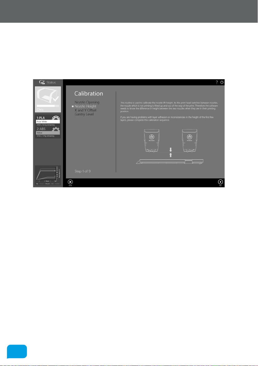
8686
7.0 Calibration and Maintenance
7.1.2 Nozzle Height
This routine is used to calibrate the nozzle li height. As the print head switches
between nozzles, the nozzle which is not printing is lied up and out of the way of
the print. Therefore the soware needs to know the dierence in height between
the two nozzles when they are in their printing position.
If you are having problems with layer adhesion or inconsistencies in the height
of the first few layers, this calibration should rectify the problem. There are a
number of things you need to check before starting the calibration sequence:
• First, remove the ‘tip wipe’ blade in the front le of the bed.
• Next, remove the PEI bed from Robox® by following the on-screen
instructions.
• The nozzles are clean with no lumps of filament or degraded material
• You will need a small sheet of paper for measurement (~50x50mm)
• A pair of tweezers (included in the accessories box) would be useful for
removing extruded material during the calibration.
When you are ready, click Start to begin. AutoMaker™ will first heat the nozzles
to prevent any solidified extrudate from aecting the calibration. Next, Robox®
will automatically determine the height dierence between the two nozzles
by probing the aluminium bed a number of times and obtaining an average
measurement.
www.cel-robox.com

8787
7.0 Calibration and Maintenance
Once this measurement is complete, place the piece of paper under the le-hand
nozzle (0.3mm/fine) and click Next. Robox® will then move the head down to grip
the paper against the aluminium bed.
Using the on-screen arrows you can adjust the height of the head. You are
looking to find the lowest position where the paper is able to slide freely beneath
the nozzle without touching. Once you are satisfied you have found this point,
press the Next button to complete the calibration. You can then re-insert the PEI
bed and resume printing.
www.cel-robox.com

8888
7.0 Calibration and Maintenance
7.1.3 X and Y Oset
This routine is used to set the alignment of the two printing nozzles in the X and Y
direction. This allows the soware to know the location of each nozzle in respect
to the other. This operation is similar to the ‘print head alignment’ found on
many desktop 2D printers.
If you having problems with the fill and fine detail parts of the print being
misaligned, this should rectify your problem. There are a number of things you
need to check before starting the calibration sequence:
• You have a Robox® SmartReel™ installed in the material dock
• You have already completed the nozzle opening and nozzle height
calibrations as described in sections 7.1.1 and 7.1.2.
• Extrusion is working correctly, and material can be extruded from both
nozzles - if this is not working, please try completing the Purge sequence
under Maintenance - see section 7.2.1
• The bed is clear of all obstructions
• The nozzles are clean with no lumps of filament or degraded material
When you are ready, click Start to begin. AutoMaker™ will then heat up the
nozzles and produce a plastic part to aid the calibration process.
www.cel-robox.com

8989
7.0 Calibration and Maintenance
On the illustration above, the output from the fill nozzle is shown in black, with
the fine nozzle shown in blue. Once the print has finished, DO NOT remove the
part, as the process is not yet complete. If the print didn’t complete successfully,
you can click the Retry Print button on the toolbar.
Compare the part on the bed to the image on-screen - you are looking for the
best alignment between the output from each nozzle (fill and fine) in the X and
Y axes. There are diagrams on the right which show the points you are looking
for. Then choose the appropriate number and letter for the profiles with the best
alignment and click Next to continue.
www.cel-robox.com

9090
7.0 Calibration and Maintenance
AutoMaker™ will then program the head with the values you have selected, and
print some extra areas for verification. It will print a circle in the rear-le corner,
followed by a crosshair in the centre.
X Alignment Error
Y Alignment Error
Perfect Alignment
If you are still seeing an alignment error, click the Retry Calibration button in the
bottom le to try again. If you are happy with the result, click Next to complete
the calibration and program the head.
X and Y Alignment Error
www.cel-robox.com

9191
7.0 Calibration and Maintenance
7.2 Maintenance
In order to keep your Robox® in good working condition, as small amount
of maintenance is occasionally required. There are a number of routines in
AutoMaker™ that guide you through the process.
• AutoMaker™ is continually being improved - please check our website for an
updated version of the user manual if you require further information.
7.2.1 Purge Nozzles
When changing between two dissimilar materials, care must be taken to ensure
the heater block does not reach the degradation temperature of the starting
material. The purge routine sets the nozzle temperature to half way between the
melting point of the new and old materials and ‘purges’ the head by ejecting
mixed material onto the bed.
AutoMaker™ will automatically detect if the melt temperature in the loaded
material profile diers from the last filament that was used in the print head,
and prompt you to complete a purge routine. It is recommended to ALWAYS
complete this routine to ensure there are no remnants of degraded material in
the head which could cause a nozzle blockage. If you would like to force a purge,
it can be accessed from the toolbar on the Status screen.
www.cel-robox.com
9292
7.0 Calibration and Maintenance
7.2.2 Eject Stuck Material
If you are having trouble extruding material, it’s possible you could have a nozzle
blockage - caused by degraded plastic (material which cannot fully melt as it has
been overheated) inside the melt chamber. The extruder fitted in your Robox®
does not always have suicient torque to overcome this blockage, and therefore
a manual purge may be required. For more information on this process, please
see the solutions page available at http://robox.freshdesk.com for instructions.
7.2.3 Speed Test
This function is purely for testing the operation of the motors and motion axes. It
is provided predominantly for diagnostic purposes, and should not be required
during normal operation of Robox®. It simply drives all axes over their full range of
movement a number of times at varying speeds to check functionality. You may
be asked to perform this test by one of our support team. It can be found on the
Advanced Settings - Calibration and Maintenance page - see section 5.3.9.
7.2.4 Cleaning
Robox® should be cleaned using a damp cloth and a mild, cleaning product (e.g.
soap solution), and then wiped down with a cloth rinsed in clean, clear water.
Wipe all surfaces and follow with a clean, dry, so cloth to bu dry.
DO NOT USE: Window cleaning sprays, kitchen scouring compounds or solvents
such as acetone, gasoline, benzene, alcohol, carbon tetrachloride, or lacquer
thinner. These can scratch and/or weaken surfaces causing small surface cracks.
• WARNING! When cleaning your Robox®, please ensure it is isolated from the
mains and is fully dry before reconnecting.
7.2.5 Print Bed
If you are having any problems with your print adhering to the bed, before trying
anything else, clean the bed using the supplied bed cleaning wipes. These
are impregnated with Isopropyl Alcohol (70%) which should remove any oily
residues which may be aecting the PEI. No other bed preparation should be
required to print with a large range of materials.
www.cel-robox.com

9393
7.0 Calibration and Maintenance
BED CLEANING WIPE
BED CLEANING WIPE
70% Isopropyl Alcohol
BED CLEANING WIPE
70% Isopropyl Alcohol
70% Isopropyl Alcohol
NOT FOR MEDICAL USE
NOT FOR MEDICAL USE
NOT FOR MEDICAL USE
0197
0197
0197
• NEVER clean the PEI print bed using Acetone or other harsh solvents/
chemicals - they are unlikely to improve adhesion, and will damage the bed
surface.
7.2.6 Build Chamber
Always try to ensure that the build chamber remains clear of debris, whether it
is mis-extruded filament or otherwise. This debris can get trapped in the various
moving parts of the machine and aect homing accuracy and motion, possibly
causing damage to Robox®.
Any debris which is fallen through into the area below the bed can be cleaned
out by removing the front tray cover (slide firmly towards you) and then tipping
forward - a gentle shake should clear it out.
To replace the cover, ensure all clips on the sides of the front tray cover are
aligned with their mating features, and then push towards the back of Robox® to
‘snap’ into place.
7.2.7 Extruder
Aer many hours of printing, there is a possibility that filament debris may have
accumulated inside the extruder. If you are having problems with loading/
unloading filament or your extruder is skipping - please see the solutions page
available at http://robox.freshdesk.com for instructions on servicing.
www.cel-robox.com

9494
7.0 Calibration and Maintenance
7.2.8 Lubrication
In order to keep your Robox® in top working condition, it is essential that you
keep all of the motion system lubricated - including the Z drive screws and linear
rails. This must be performed at regular intervals (approximately 200 hours of
printing). There is a bottle of axis lubricant included in the accessories box which
shipped with your Robox® - if this is not available, a light mineral oil would be
suitable e.g. sewing machine oil.
To complete this process follow the instructions below:
1. Home all axes using AutoMaker™.
2. Apply a thin smear of lubricant to the X-Rails. The easiest way to ensure the
lubricant is distributed across the rails is to apply it on either side of the linear
bearings for the X (head) and Y (bed) carriage, and to the drive nuts for the Z
axis. If you then run a speed test, this will distribute the lubricant over all axes.
www.cel-robox.com

9595
7.0 Calibration and Maintenance
7.3 Troubleshooting
This section of the user manual is intended to help you diagnose and fix a wide
range of issues you could be experiencing with your Robox®.
Problem / Symptoms Solution(s)
Robox® will ‘play dead’ unless the
AutoMaker™ soware is running. Also ensure
Hardware - My Robox® won’t turn
on - is it dead!?
Hardware - I’m having trouble
getting the first layer of my print to
stick to the print bed.
the USB cable is connected, the power
switch on the rear of the unit is in the ‘On’
position, and the fuse in the plug is intact. If
you are still experiencing problems, please
contact CEL support.
There are a number of possible causes and
solutions:
1. Try cleaning your print bed using the
supplied bed cleaning wipes, or a clean cloth
soaked in Isopropyl Alcohol.
2. There could be a problem with the
automatic bed-levelling system - try running
the ‘Level Gantry’ calibration.
Hardware - My motors/bearings are
making a ‘grinding’ sound as the
print head moves around the build
area.
www.cel-robox.com
It sounds like you need to perform some
maintenance, try lubricating the drive
screws and motion rails using the supplied
Axis Lubricant. See section 7.2.8 for more
information on maintenance procedures.

9696
7.0 Calibration and Maintenance
Hardware - I’m having trouble
loading a new reel of filament
Hardware - There’s a clicking sound
coming from my extruder during
printing.
Firstly, ensure that you have fed filament all
the way to the feed wheels. When you insert
the filament, you should hear the extruder
motor begin to turn, at this point continue
pushing in material until the extruder grabs
hold of the filament and feeds it all the way
to the head. If you do not hear the extruder
motor start when you feed in filament, it
is likely there is an issue with the ‘loaded’
switch in the extruder. When no reel is
installed, the extruder output switch should
appear as ‘false/o’ in the diagnostics screen
(described in section 5.3.10). There should
also be no eject button visible on the Status
screen. If you do see an eject symbol when
no filament is loaded, then there is an issue
with your output switch, please contact CEL
support - see section 8.4.
1. Verify the material is coming of the reel
easily and isn’t tangled.
2. Your extruder may require cleaning - this is
a simple procedure that can be performed
using a household vacuum cleaner. See
section X.X for further information.
3. Your printhead could be blocked. Try
running the purge procedure to clean
out any degraded plastic that may have
accumulated in the melt chamber.
If these procedures have no eect, please
contact CEL support.
www.cel-robox.com

9797
Printing - My print is stuck to the
bed. Help!
Printing - Object begins to warp
and peel away from the bed during
printing.
7.0 Calibration and Maintenance
Sometimes, depending on the print material
you are using, your print can be stuck to
the bed very securely, making it diicult to
remove. The first step is to ensure your part
and bed have cooled down fully; because
dierent polymers have dierent shrink rates
when cooling, the part will usually cool at a
dierent rate to the PEI sheet, causing them
to detach themselves. Because the bed is
removable, this should be simple to resolve
by removing the PEI sheet - see section 4.5.
Once you have removed the sheet, lightly
flex it and you should find your print snaps
right o.
The warp of printed parts is influenced by
the ‘coeicient of thermal expansion’ of
the material. This parameter describes the
degree to which a polymer changes size as
a function of temperature. The higher this
parameter, the more a part will shrink as it
cools. Because 3D printed parts are hot at
the base (due to the heated bed) and at the
top (due to the molten material which was
deposited last), but cooler in between, the
middle of the part can start to shrink at a
higher rate. This causes the bottom of the
part to warp upwards, and the top to warp
downwards. By maintaining the ambient
temperature, Robox® attempts to prevent
the part shrinking, by allowing the whole
object to cool evenly at the end of the print.
Therefore when printing materials with a
high shrink rate, it is essential that the door
remains closed during printing. Using brim
can also help with warp at the bottom of the
part by increasing the contact surface area
with the PEI sheet.
www.cel-robox.com

9898
7.0 Calibration and Maintenance
Soware - I can’t get AutoMaker™ to
install on my OS.
Soware - My antivirus soware
has detected a problem with
AutoMaker™.
Soware - I can’t find the print
button!
Firstly, please check that your hardware
meets the minimum requirements as stated
in section 2.3 and also that you are using a
compatible operating system as described
in section 2.2.6. If your system meets these
requirements, please contact CEL support.
This is likely a ‘false positive’ based on
‘reputation’. Many antivirus packages use a
reputation based system to determine the
safety of soware based on the number
of instances that have been seen by other
users. As AutoMaker™ is brand new sofware
it may trigger these checks until it has been
installed by more users worldwide. It can
usually be rectified by restoring the file from
quarantine. If you have any further questions
please contact CEL support - see section 8.4.
The print button only appears when your
printer is ready to print. The normal cause
is that your filament is not installed. Please
see the troubleshooting section “Hardware
- I’m having trouble loading a new reel of
filament”.
www.cel-robox.com

9999
7.0 Calibration and Maintenance
www.cel-robox.com

8.0
Supplementary
Information
 Loading...