

Page 1

WiNRADiO
G3 Series Radio Receiver
User’s Guide
i
Page 2

Published by
WiNRADiO Communications
PO Box 6118, St Kilda Road, Melbourne 3004, Australia
© 2002 WiNRADiO Communications, Melbourne
All rights reserved. No part of this book may be reproduced or transmitted in any form or by
any means without the written permission of the publisher.
Trademarks
WiNRADiO, G3 and G303 are trademarks or registered trademarks of Rosetta Laboratories
Pty. Ltd.
All other brand and product names are trademarks or registered trademarks of their respect ive
owners.
Patents
WiNRADiO technology is protected by US Pat. No. 6,289,207 and other pending US and
international patent applications.
Printed in Australia
- ii -
Page 3

FCC Notice
The WiNRADiO G3 SERIES receiver has been tested and found to comply with the limits for a
Class B digital device, pursuant to Part 15 of the FCC Rules. These limits are designed to
provide reasonable protection against harmful interference i n a residenti al installation. This
equipment generates, uses and can radiate radio frequency energy and, if not installed and
used in accordance with the instructions, may cause harmful interference to radio
communications. However, there is no guarantee that interference will not occur in a particular
installation. If this equipment does cause harmful interference to radio or television recept i on,
which can be determined by turning the equipment off and on, the user is encouraged to try to
correct the interference by one or more of the following measures:
Reorient or relocate the receiving antenna
•
Increase the separation between the equipment and the receiver
•
Connect the computer into a different outlet so that the two devices are on different
•
branch circuits
Consult an authorised dealer or an experienced radio/TV technician for help
•
Caution
To comply with the limits for the Class B digital device, pursuant to Part 15 of of the FCC rules,
the WiNRADiO card must be installed in computer equipment certified to comply with the Class
B limits. Only peripherals certified to comply with the Class B limits may be attac hed to the
computer containing the WiNRADiO receiver. All cables used to connect the computer and
peripherals must be shielded and grounded. Operation with non-certified peripherals may
result in interference to radio and TV reception.
Modifications
Any changes or modifications to the WiNRADiO receiver not expressly approved in this book
could void the user's authority to operate this equipment.
Limitation of Liability and Remedies
The information published in this book has been compiled from several sources. While every
effort has been made to ensure its accuracy, neither the authors nor the publisher can
guarantee that all information is entirely correct or up-to-date. Furthermore, neither t he authors
nor the publisher can take any responsibility for the use of this information or any
consequences arising therefrom.
WiNRADiO Communications shall have no liability for any damages due to lost profits, loss of
use or anticipated benefits, or other incidental, special or punitive damages arising from the use
of, or the inability to use, the WiNRADiO receiver, whether arising out of contract, negligence,
tort or under any warranty, even if WiNRADiO Communications has been advised of the
possibility of such damages. In no event shall WiNRADiO Communications ' liability for
damages exceed the amount paid for this product. WiNRADiO Communications neither
assumes nor authorises anyone to assume for it any other liabilities.
Warning
In certain countries or states it may be illegal to monitor certain frequencies. We cannot accept
any responsibility for the consequences of your non-compliance with government regulations.
If you are in doubt about the regulations in your country or state, please contact your nearest
radio communications regulatory authority.
- ii -
Page 4

Introduction
Introduction
One could easily conclude that, in the era of the Internet and communication
satellites, short waves are destined for obsolescence. But the reality is quite
different. On the contrary, shortwave communications seem to be
experiencing a new period of revival and vigorous growth.
This revival is partially caused by the fact that shortwave is still the only
technology able to send signals around the globe with minimum power and
without the need for expensive, and potentially failure-prone or sabotageprone infrastructure. In the era of increased security concerns, this is an
important reason for the continuing interest in shortwave.
The other reasons include newly found applications, for example HF email,
and emerging new types of digital modulations (such as DRM broadcasting),
offering more reliable and higher quality communications than before.
All this will ensure that shortwave will remain what it always has been; an
amazing place of action, a cacophony of sounds; a babel tower of exotic
languages and music, alive with broadcasters both official and clandestine;
a haven of spies; a playground of pirates, terrorists and freedom fighters
alike; an exciting mix of the respectable, the serious, the crazy and the
dangerous. Long before the Internet, the shortwave world was always
borderless. And quite like the Internet, impossible to tame and control.
Welcome to shortwave. And welcome to the WiNRADiO G3 SERIES
receiver. Your new receiver is a world-first in more than one respect. Most
importantly, it is the first commercially available
(SDR), where the entire demodulator and the last intermediate frequency
stage are performed by software running on a personal computer rather
than using conventional hardware circuits, or a dedicated Digital Signal
Processor. Your PC probably has more power than even the fastest DSP
had only a few years ago. Your new WiNRADiO G3 SERIES receiver is now
ready to take advantage of that power. Enjoy!
WiNRADiO provides regular upgrades to our application software. Don’t
forget to register as a WiNRADiO user to receive news about new products,
accessories and software upgrades for your WiNRADiO G3 SERIES
receiver. Use our on-line registration form on
to take advantage of this free service.
Software Defined Receiver
www.winradio.com/register
3
Page 5

Installation
Installation
The WiNRADiO package contains the following items:
• WiNRADiO G3 SERIES receiver card
• WiNRADiO software on a CD ROM
• Start-up indoor antenna
• Audio cable
• This User’s Guide
• Warranty information
In order for the WiNRADiO receiver to function, your IBM PC compatible
computer must meet the minimum system requirements specified below.
System Requirements
Minimum Recommended
CPU 500 MHz,
Pentium III
RAM 64 MB 256 MB or more
Display SVGA SVGA (16 mil. colors)
HD free space 20 MB 40 MB
Sound card SoundBlaster
compatible, 16 bit,
full duplex
OS Windows
98/ME/NT/2000/XP
1GHz or higher,
Pentium IV or Athlon
Creative Sound Blaster,
16 or 32 bit
Windows
98/ME/NT/2000/XP
Hardware Installation
1. Turn the off computer and disconnect the power cord.
2. Remove the computer case. Choose an empty PCI slot, as far as
possible from the power supply and from other cards.
4
Page 6

3. First touch the computer metalwork with your hand to drain any static
charge, then carefully insert the card into the vacant slot and push down
until it is firmly seated. Screw the metal bracket at the end of the card to
the computer case.
the card)
4. Replace the computer case and reconnect the power cord.
5. Connect the supplied audio lead between the receiver output (a
standard audio jack) and the sound card Line Input.
input on your PC, as is the case with some laptops, you may use
alternative inputs, such as the Microphone input.)
6. Connect the supplied start-up antenna to the SMA connector at the rear
of the card.
7. Extend the antenna so that it is as far away from the computer as
possible.
Please use only the WiNRADiO-supplied audio lead cable to connect the
receiver to the sound card. This is a stereo cable (as is the case with all
standard PC multimedia cables). Mono jacks are not compatible with stereo
ones because they short the right channel to ground. A mono cable should
not be used under any circumstances and will not work with the G3 SERIES
receiver.
.
(This must be done to provide proper grounding for
(If there is no Line
Software Installation
1. After installing the card, turn the PC on. Windows will find the card and
automatically start the usual
routine. Insert the installation CD ROM into the drive, and follow onscreen instructions.
card, as it does not support Plug and Play.)
2. After installing the drivers, choose the
menu in Windows and type D:INSTALL (if the CD ROM is the D: drive
on your PC).
3. This will run the application installer, which will guide you in the
installation process.
4. After all the files have been installed to your hard disk, run the
WiNRADiO G3 SERIES application.
(Note: Windows NT will not automatically detect the
New hardware found
Run
driver installation
command from the
Start
- 5 -
Page 7
Note: If the card is not detected by Windows, you can simply skip the driver
installation procedure, insert the CD ROM, and run the installation program,
which will also install the driv er s .
After installing the hardware and software, you will now need to set-up the
sound card parameters. This is done both in the WiNRADiO application and
in the Windows sound card control panel – this provides the actual
connection between the receiver
radio system.
front-end
and the PC
back-end
of your
Setting up the Sound Card
In computer terminology a sound card is a
have several such wave devices installed (for example a modem with voice
capabilities). That’s why you need to select the sound card as the desired
wave device first. Start the WiNRADiO G3 SERIES application and click on
Setup
the
The Demodulator set-up window opens, as shown:
button (located below the
wave device
USB
button) in the Demodulator panel:
. A computer may
- 6 -
Page 8

Wave device
The
Windows default
| Control Panel | Multimedia Properties | Audio
in this Control Panel setting for both playback and recording (this is very
likely, but not always necessarily so), then you can simply select
Default
name of the sound card should be selected. The selected sound card
support duplex operation
samples/second sampling rates, 16 bits per sample, stereo. Most modern
sound cards do satisfy all these conditions, but some cards may have a high
level of distortion at 48000 samples per second; for such cases, the 44100
samples/second sampling rate is provided.
The next parameter to select is the mixer device associated with the already
selected sound card, using the
line
an external cable, the cable should be physically connected to the
Input
probably the input would be called
as the
(the sound card input line). If the signal is arriving at the sound card via
of the sound card. If the receiver is connected internally, most
drop-down list shows all the installed wave devices:
is the Control Panel setting specified under
. If a sound card is specified
wave device
for the demodulator. Otherwise, the specific
and the standard 44100 or 48000
Mixer device
Aux
drop-down list, and the
CD Line
or
.
Start | Settings
Windows
must
Mixer
Line
With some laptops, only the
case you will need to connect the receiver to this input, and also select this
input in the software.
In the drop-down list of sound card inputs, each line is available either as
normal, or
Right and Left channels (of the sound card stereo input) are to be reversed.
Normally, you should not need to select any of these reverse inputs.
However, there is a very small number of sound cards where the Left and
Right inputs are swapped. Normally, the G3 SERIES Demodulator expects
the receiver output to be connected to the Right sound card input. If it is to
Reversed
. If the reversed line is selected, this means that the
Microphone
input may be available; in such
- 7 -
Page 9
be connected to the Left input instead, the revers e in put line needs to be
selected from the drop-down list.
These are all the settings required on the WiNRADiO G3 SERIES
application side. Now you need to set up your Windows sound card control
panel, and the marriage between the radio and the PC will be com plete.
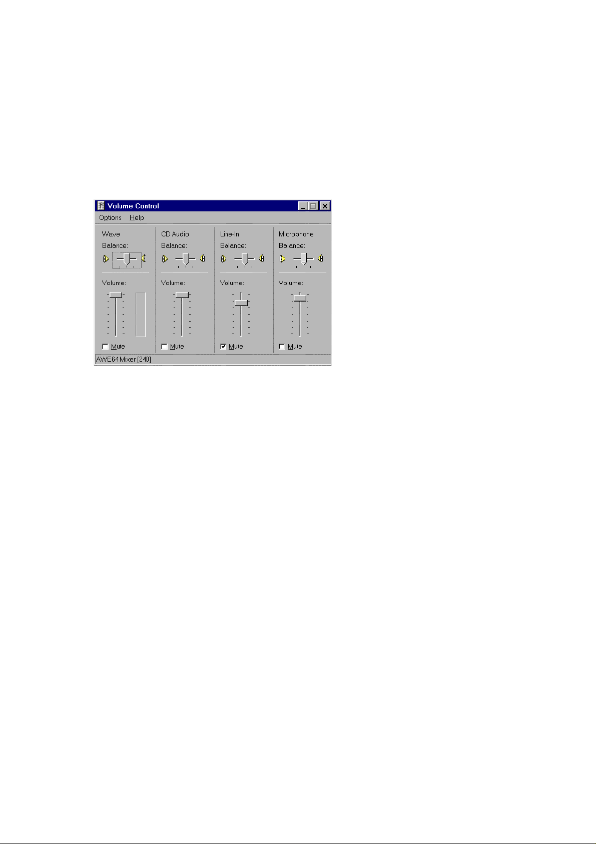
Click on the speaker icon in the task bar in the bottom, to bring up the sound
card
Volume Control
you have difficulties locating and the sound card settings).
panel (consult
Appendix B – Sound Card Controls
if
Sound Card Volume Control Panel
Mute the input line the receiver is actually connected to. (This is the same
line as selected in the WiNRADiO G3 SERIES Demodulator Setup. Usually,
this will be the
Why are we muting the input line? This is because the signal coming from
the receiver is not an audio signal, but rather the intermediate frequency
signal. It needs to be processed (demodulated) by the PC first, before it is
output back to the sound card. (That’s why the sound card needs to be full
duplex, to allow for such simultaneous input/output processing.)
Failure to mute this line will cause a high-pitched intermediate frequency
sound to be combined with the demodulated signal.
Line-In
input.)
- 8 -
Page 10
If you are using the Microphone input instead of Line input, please check if
there is an
sound card control panel. If so, then click on it and uncheck the
check box if it exists. (The extra large gain would result in overloading the
sound card and cause distortion.)
Advanced
button under the Microphone volume control in the
+20dB gain
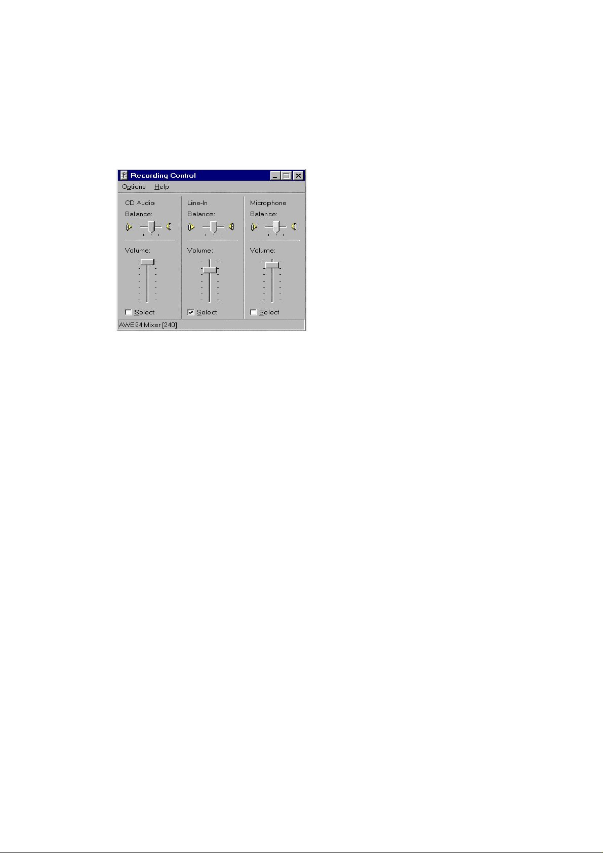
The same line must be now selected in the
card control panel. To get to the Recording Control, you need to select
Options | Properties | Recording
panel.
Sound Card Recording Control
The position of Volume control slider should be set to approximately half, to
get started. The same control is duplicated in the Demodulator Setup panel
(where it is labeled
Input level
in the top bar menu of the Volume Control
).
Recording Control
of the sound
You can adjust this level either in the sound card recording window, or,
preferably, return to the Demodulator Setup panel to take advantage of the
Clipping indicator
input signal clipping, i.e. just before the Clipping indicator turns red.
While adjusting the input level, you will also see the floor of the signal
spectrum shown in the main demodulator window rising proportionally.
Please pay attention to the
associated with using this type of receiver can be attributed to an incorrect
sound card setting. Typical problems include:
. The
input level
must be adjusted below the point of the
sound card set-up
, as most initial problems
- 9 -
Page 11

• Not selecting the Recording input line correctly (which will manifest itself
by the absence of any signal appearing in the spectrum scope);
• Failing to mute the Volume control line (which will result in listening to
the high-pitched 12 kHz intermediate frequency sound superimposed on
the demodulated signal);
• Failing to adjust the signal input level properly, which may result either in
low (or no) audio output, or, on the other hand, distortion if the signal
level is too high.
Getting Started
There is often a degree of understandable impatience when exciting new
equipment such as a new WiNRADiO receiver is acquired. The following
fast-forward introduction makes it possible for you to start using your new
acquisition as quickly as possible. Detailed operation is described in the
subsequent chapter
will return to that chapter, as the WiNRADiO G3 SERIES receiver has many
fine features which it would be a shame to miss.
Start the WiNRADiO G3 SERIES receiver application (double clicking on the
WiNRADiO icon). The WiNRADiO G3 SERIES receiver control panel will
appear as shown in the next page.
Using WiNRADiO G3 SERIES Receiver
. We hope you
Did you know?
The first shortwave transmission across the Atlantic was accomplished by
six US radio-amateurs on December 11, 1921. The message was picked up
by a Scottish radio-amateur. This achievement sparked a period of intensive
research and development which led to wide-spread use of short waves.
(Before then, it was believed that frequencies over 1.5 MHz were useless.)
- 10 -
Page 12
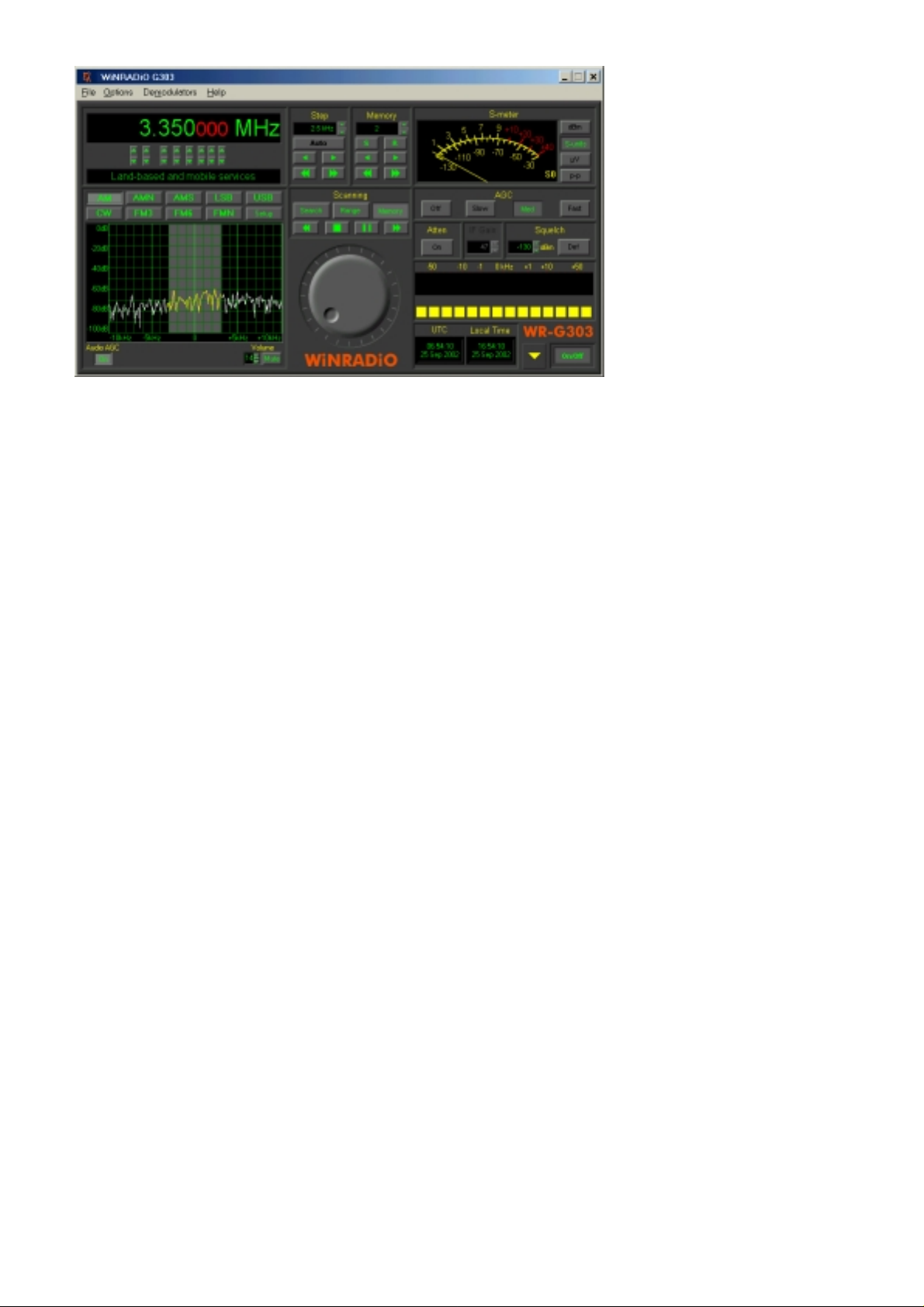
WiNRADiO G3 SERIES Receiver Control Panel
The WiNRADiO G3 SERIES receiver control panel has some elements
similar to from conventional shortwave receivers, and many additional
features as well.
The quickest way to get started with this receiver is to check its operation on
local AM stations.
Using the keyboard, type in the frequency of one your local AM stations:
For example, for 774 kHz, type in
The typed-in frequency will appear on the digital frequency display. Then
select the AM mode by clicking on the AM button. At this point, you should
hear the station. You can adjust the volume using the two buttons next to
the small Volume display. (Note also the little slider between these two
buttons: you can drag it up and down to change the volume faster.)
Manual tuning can be done in several ways. Let’s start with the tuning knob:
Place the mouse cursor to the upper half of the tuning knob, at which point
you will see the cursor change to a curved double ended arrow. Hold down
the right or left mouse buttons to increase or decrease the frequency, and
the knob will rotate clockwise or anti-clockwise, respectively. If you place
your cursor in the bottom half of the tuning knob, the direction of the rotation
will reverse.
7 7 4
, then k for kHz, then press
Enter
.
- 11 -
Page 13

The rotation increment of the tuning knob is 0.5 kHz. This can be changed
easily using the Shift, Ctrl or Alt keys: If you press the Shift key while tuning,
the increment will increase ten times (to 5 kHz). Pressing Ctrl will increase
the increment a hundred times (50 kHz). On the other hand, if you use the
Alt key, the increment becomes ten times finer: 50 Hz.
If you are still unable to tune to any stations at this point, please refer to
Appendix A - Troubleshooting
There are also several other ways to tune the WiNRADiO receiver other
than typing the frequency or using the tuning knob. These will be explained
in detail in the
Using WiNRADiO G3 SERIES Receiver
.
chapter.
Connecting the Antenna
Your WiNRADiO G3 SERIES receiver comes with a start-up antenna
consisting of a 3-meter length of coaxial lead-in cable, with an additional 3
meters of insulated wire. The thinner, insulated wire at the end is the actual
antenna. The lead-in cable is necessary for the antenna to be as far away
from the PC as possible, to reduce interference from the PC.
Please note that this start-up antenna is supplied for immediate gratification
only and is not intended to replace a good shortwave antenna.
The best placement of the start-up antenna depends on your actual
situation, and will often involve some experimentation. However, the basic
rule is simple: Place the antenna as close to the window as you can, and
keep the active part of the antenna as far away from the PC, and other
electronic and electrical devices, and metal objects, as possible.
Did you know?
The first commercial shortwave station was Radio Luxembourg. It was the
first station to target areas outside of its own country with programs in other
languages. For most of the 20th century, this was the most powerful
shortwave station in Europe.
- 12 -
Page 14

An example of WiNRADiO start-up antenna placement
No matter how good a radio receiver is, the performance of the entire
receiving system will depend on the quality of the antenna. The same
applies to a WiNRADiO receiver. To make most of your WiNRADiO receiver,
you should install a proper shortwave antenna. There are many vendors
offering shortwave antennas. WiNRADiO may also be able to assist – check
our Web page
Did you know?
During the cold war, the Soviet Union and other Communist countries used
to jam shortwave transmissions such as the BBC, Voice of America, Radio
Free Europe and Deutsche Welle to their own citizens. The Soviet Union
alone was spending about $1 billion per year on jamming, and had 200
jamming stations that were continuously pumping out 600 Megawatts of
power.
www.winradio.com
.
- 13 -
Page 15
Using WiNRADiO G3 SERIES
Tuning to a Frequency
To change frequency, simply type the new frequency into the keyboard. As
soon as you press a number or decimal point, the frequency display will
activate, waiting for a frequency to be typed. You can also click on the
display to type in a new frequency. After typing the new frequency, press
Enter
and the receiver will instantly retune. To abort, press
To enter units, such as kHz or MHz, simply press K for kHz or M for MHz
after entering the digits. Any invalid keystrokes are ignored. Frequencies
outside the receiver limit (9 kHz to 30 MHz) will not be accepted and the
display will revert to the previous frequency.
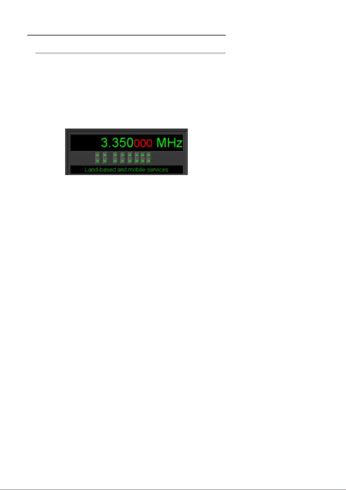
WiNRADiO G3 SERIES Receiver Frequency Display
The up/down buttons under the individual digits make it possible to quickly
step up or down the frequency in the corresponding positions. (The little
slider buttons between the up/down buttons can be used for faster
adjustment.)
Escape
.
Under these buttons there is a
band allocation of the currently tuned frequency. These band descriptions
are based on those applicable to North America. However, these
allocations are based on international treaties and therefore are generally
applicable worldwide.
Note that the default band allocation can be overridden with a call sign or a
user-defined description of a frequency stored in memory. The default band
description is also user modifiable: it resides in the file
WiNRADiO installation folder. This file can be edited using a spreadsheet
application, such as Microsoft Excel.
band description window
. This shows the
bands.csv
in the
- 14 -
Page 16

Fine Tuning
The Fine Tune knob makes it possible to finely adjust the frequency in
0.5 kHz steps.
WiNRADiO G3 SERIES Receiver Tuning Knob
To use the tuning knob, position the mouse cursor over the knob (the cursor
will turn into a curved double ended arrow) and click on either the left or right
mouse button. If the cursor is on the top half of the knob, the left button will
decrease the frequency, and the right button will increase the frequency. If
the cursor is in the lower half, the opposite will occur (and the cursor will
invert its shape).
Using the keyboard only, the frequency can be similarly adjusted using the
up/down
To speed up tuning, the step size can be increased ten or one hundred
times by holding the
knob with mouse button or using the
very convenient feature if you wish to tune quickly across a frequency range:
hold the mouse button and accelerate the movement by pressing the
Ctrl
or
step ten times (to 50 Hz).
cursor keys.
Shift
keys. On the other hand, pressing the
or
Ctrl
keys respectively, while clicking the tuning
up/down
keyboard keys. This is a
Alt
key will reduce the tuning
Shift
Did you know?
Most Space Shuttle astronauts are radio amateurs and the first elements of
a permanent amateur radio station in space have already been despatched
to the International Space Station.
- 15 -
Page 17
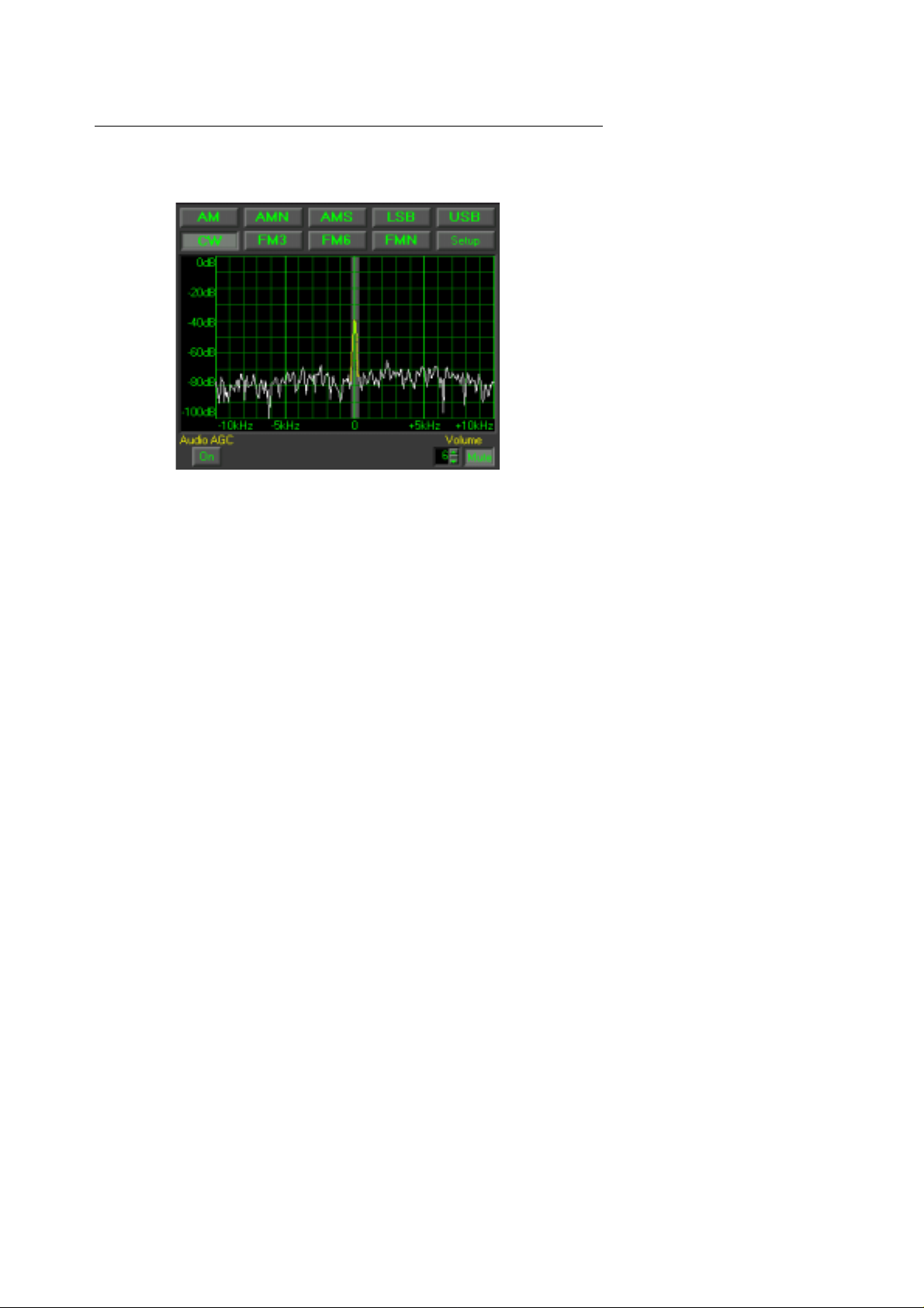
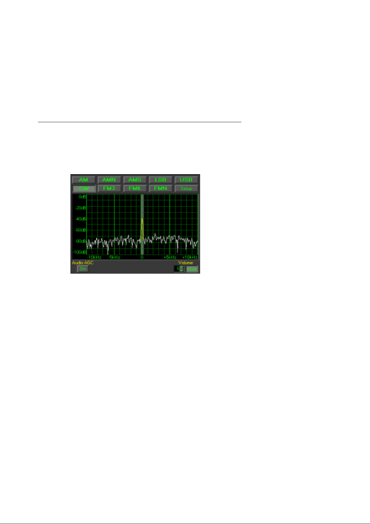
Setting the Modulation Mode
To select the modulation mode, click on the appropriate Mode button in the
Demodulator panel:
WiNRADiO G3 SERIES Standard Dem odu lat or Pane l
The real-time spectrum display shows the output of the receiver (i.e. the
intermediate frequency signal) as it is applied to the PC sound card. When
you press the mode buttons, you will note that the central highlighted region
of the spectrum changes its width. This corresponds to the IF (intermediate
frequency) filter bandwidth associated with the different modulation modes.
For example, standard AM mode has 6 kHz bandwidth, while narrow AM
(AMN) uses 4 kHz bandwidth. The CW mode uses a narrow bandwidth of
500 Hz. You will see the trace color change from white to yellow where the
spectrum falls within the filter bandwidth. This indicates that you are only
receiving the yellow part of the displayed spectrum and the surrounding
frequencies are rejected.
If you mistune the receiver somewhat, you will see the spectrum shifting.
This assists you to tune the receiver right to the center of the transmitter
frequency, and to select the correct AM mode to avoid interference from
adjacent signals.
- 16 -
Page 18
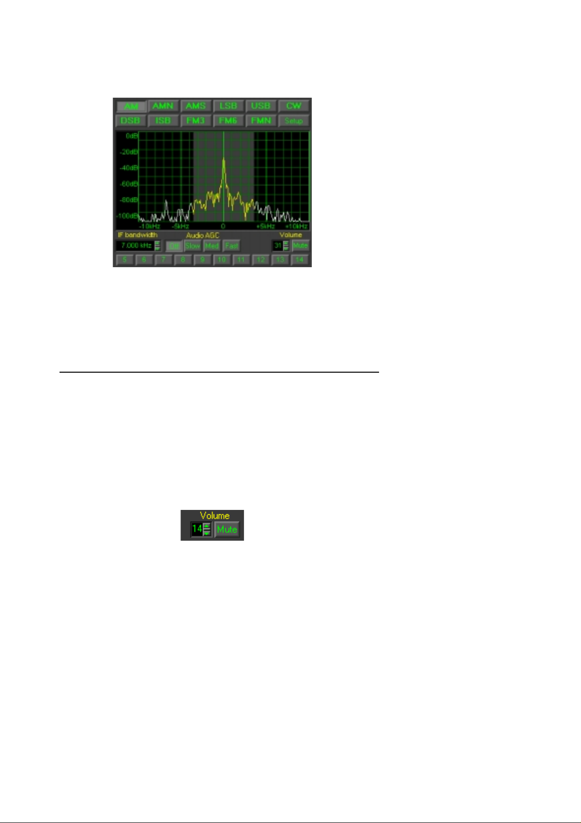
If you also purchased the optional
this demodulator from the
such as volume control, audio muting and mode selection are identical to
the Standard Demodulator.
WiNRADiO G3 SERIES Professional Demodulator
For details of the additional functions such as continuous IF bandwidth
adjustment and other special features of the Professional Demodulator refer
Appendix E - Professional Demodulator
to
Demodulators
Professional Demodulator
top bar menu. The basic functions
.
, you can select
Volume Control
The
Volume control
can range from 0 (no sound) to 31 (full volume). To enter a value directly,
click on the display and type in the new volume level. The volume can be
also increased or decreased by clicking on the up/down buttons next to the
volume display.
Another convenient way of changing the volume is by using the small
button between the up/down buttons. Place the mouse cursor on it and see
the cursor shape change, to indicate a ‘slider’ type of control. Hold down the
left mouse button to drag the slider up or down and the volume will change
accordingly.
is also located in the
Demodulator panel
. The volume
slider
- 17 -
Page 19

Finally, another convenient way of changing the volume is using the
right cursor
keys on the keyboard.
Mute Control
left
and
Next to the Volume control is the
audio output quickly. It is faster to use than setting the volume to zero, with
the added benefit of not changing the set volume level. To use the mute
control, simply click on this button. Click again to release.
button, which allows you to switch off
Mute
AGC
The
Fast
which the AGC reacts. Typically, the AGC would be in the Medium position.
The receiver must process a considerable variation of signals, ranging from
very weak to very strong. This requires the sensitivity of the receiver to vary
according to the incoming signal strength.
The incoming signal can var y in intensi t y, with changi ng pr opa gat io n
conditions, and also depending on the modulation type and content. For
example, with CW signals (where information is transmitted by keying the
transmitter on and off), the signal strength will vary substantially during the
transmission. The demodulated signal will then sound better with a slow
AGC (so that the receiver will not have time to increase the gain during the
“off” intervals, and so increase the background noise and causing a raspy
sound).
(Automatic Gain Control) has four settings:
AGC
. These make it possible to disable the AGC, or to select the speed with
AGC Control
Off, Slow, Medium
and
On the other hand, use fast AGC when listening to especially weak signals
buried in static and noise. Otherwise, each new burst of noise would
desensitize the receiver for a long time and you could miss long periods of
useful transmissions.
If unsure, use the medium speed AGC setting.
- 18 -
Page 20

IF Gain
The AGC can be turned off entirely, using the
gain must then be adjusted manually. This is done using the
Note that by setting an excessive gain, the receiver will overload and the
demodulated signal will be distorted. On the other hand, if the gain is too
low, it will make the receiver appear “deaf”.
Manual IF Gain setting is useful for hunting for very weak signals buried in
noise.
Manual IF Gain Control
The IF Gain control is only enabled when the AGC is switched off. The gain
“value” ranges from 0 to 100, where 100 corresponds to maximum gain.
AGC Off
button. The receiver
IF Gain
setting.
Audio AGC
The
Audio AGC
supplementary function to the main AGC. (The main AGC employs a
hardware circuit, while the Audio AGC works in software.)
facility is available in the Demodulator panel, and provides a
Audio AGC
Audio AGC is useful to compensate for audio volume changes when the
antenna signals are so weak that the main AGC is not yet activated, or when
the main AGC is disabled and the manual IF gain is used.
- 19 -
Page 21

Attenuator
The
Attenuator
(i.e. 6 times).
Why would you ever need to reduce the sensitivity? This is because
unusually strong signals from local stations may occasionally cause
overloading. This overloading can make the reception worse, and even
cause stations to appear on frequencies, where none exist (
Appendix C - Dealing with Interference
See
phenomenon.
If a received signal is too strong, causing overloading, distortion or the
appearance of ghost stations, you should reduce its level by pressing the
Attenuator button.
makes it possible to reduce the receiver sensitivity by 18 dB
Attenuator
stations).
ghost
for more information on this
Squelch Control
The
Squelch control
being received. Without a signal, all you will usually hear is noise. Squelch
is provided to cut out the noise until a station is found, making the receiver
more comfortable to use.
can be used to mute the receiver when no signal is
Squelch Control and Squelc h Defeat Button
The squelch setting controls the signal level at which muting occurs. Muting
will occur when the signal level drops below the squelch level. When a
signal of a higher level returns, the sound will be restored immediately.
- 20 -
Page 22

The squelch is always shown in
first tune to an unoccupied frequency that produces only noise. Increase the
squelch until the receiver is muted. You will see the red-colored segment of
the S-meter growing until it gets higher than the current S-meter value. At
that moment the receiver will be muted. Add a few dB extra (to allow a
margin for background noise fluctuation on the band). Now when you tune to
an occupied frequency, if its signal strength is higher than the squelch level,
the receiver will be unmuted.
units. To adjust the squelch control,
dBm
Next to the squelch setting is the
activated, the squelch action will be turned off (it is the same as if the
squelch was set to its lowest level, but more convenient). The red segment
in the S-meter will turn blue to indicate this condition.
It is easy to forget that squelch is active. If the receiver doesn’t seem to be
operational (no sound from the speaker), check the squelch and mute
settings first.
Squelch Defeat
Def
(
) button. When
Frequency Stepping
The
Frequency Stepping
frequency step size. To change the step size, click on the associated display
and enter the required value (from 1 Hz to 1 MHz). You can also use the
up/down buttons on the right of the display, to select from commonly used
step sizes. For convenience, you can also use the small slider between the
two buttons.
facility makes it possible to specify an arbitrary
Frequency Stepping Panel
When the step size is selected, you can step up/down from the currently
displayed frequency using the left/right arrow buttons under the Step size
display. The double-arrow buttons further down will cause stepping by a
step size ten times larger. Stepping can also be done using the keyboard
Up/Down
keys .
Pg
- 21 -
Page 23

For example, if you wish to browse the AM broadcast band (approx. 530 to
1620 kHz), set the step size to 10 kHz (for North and South America) or
9 kHz (for the rest of the world), which is the channel separation for AM
broadcast stations. Tune manually to any station first, then step up or down
to browse the band. To browse the shortwave broadcast stations (2.3 to
30 MHz), 5 kHz works well.
This type of fixed-size stepping is convenient if you wish to explore a
frequency band where the channels are equally separated. However, you
should ensure that the stepping frequencies fall on the actual channel
frequencies in the band. If you know the channel separation but are unsure
about the exact frequency of the first channel, tune to an active channel
using manual tuning first, and only then step up or down in fixed steps.
Auto
The
enhancement over fixed stepping. When properly configured, auto-stepping
will automatically set the step size according to the frequency you are tuned
to. Auto-stepping can be also used to associate particular mode and squelch
settings with specified frequency ranges.
button engages
Auto-stepping
, which provides a significan t
To configure the auto-stepping ranges, go to
top bar menu. The following window opens:
You can use the
to specify the start and end of the range, step size, and optionally mode,
squelch and description. You can specify as many such bands as you like.
When done, close the window.
Next time when you tune to a frequency, and the
the step size (and optionally mode and squelch) will be set to the predefined
value if the new frequency falls within a specified auto-step range.
New
button to add a new range. For each range, you need
Options | Autostepping
Auto
button is pressed,
in the
- 22 -
Page 24

Frequency Memory
The WiNRADiO G3 SERIES receiver has the ability to store up to one
thousand frequencies in one memory file. It also allows you to load and save
different memory files for a huge amount of total storage, limited only by the
size of your hard disk.
Memory Control Panel
Storing a Frequency into Memory
With each frequency, you can store several attributes: mode, callsign, user
comment, group assignment, squ elch and a hotkey.
To store a frequency into memory, the receiver must first be tuned to that
frequency (and the appropriate mode must be selected if you also wish to
store the mode). Next click on the S button in the Memory Control Panel as
shown above.
A
Store frequency
number to the current frequency.
Did you know?
The first shortwave message from the UK to Australia was received on
March 6, 1924. On April 8, 1927, the regular Australia-Britain wireless
service started operating, and the AWA company (Amalgamated Wireless
Australasia Ltd.) built a shortwave receiving station at La Perouse, a suburb
of Sydney (named after the French explorer La Perouse, who in 1788 was
the first Frenchman to arrive in Australia).
dialog box will pop up, allowing you to assign a memory
- 23 -
Page 25

Storing Frequency to Memory
At the top of the dialog box is the frequency you are storing. The next line
shows the next available memory number. You can change this to another
memory number if you wish (including one which is already allocated).
The third item contains the group assignment buttons. You can assign the
frequency to one or more of 16 different groups (whose meaning you define
yourself). When you are searching or scanning for a particular type of
frequencies (for example “Airforce”), the group assignment will allow you to
confine the searching and scanning to that particular type.
Note that a frequency may be associated with more than one group at the
same time.
There are also several additional items that can be optionally stored with
each frequency:
- 24 -
Page 26

• Most stations have a name or callsign. You can store up to 11
characters in the
• For quick tuning to your favorite stations, you can assign
Hotkeys
frequencies. If you then press a hotkey, the associated
frequency will be instantly recalled. Hotkeys which are already
assigned will be shown in this dialog box as ‘used’, however
you can overwrite the previous assignment with a new one if
you wish.
(function keys F2 to F12) to up to eleven different
Callsign
field.
• User
• The
• Finally, a
Finally, when everything has been set, click on OK or press
the new frequency.
Comments
of the comments is limited to 31 characters.
Mode
will be then set automatically when the frequency is recalled.
Memory Scan Lock-out
memory, which means that the memory will not be included in a
memory scan. In the memory Recall window, such memories
will be shown with a small ‘x’ preceding the memory number.
can also be stored with a frequency. The size
and the
Squelch
values can also be stored, which
can be set for each
Enter,
Recalling a Frequency from Memory
There are several ways to recall a frequency from memory:
• Using Memory Recall
• Typing a number into the memory number display
• Using a hotkey
• Memory stepping
To recall a frequency, click on the R button. A dialog box will pop up
showing a list of all memory frequencies.
to save
To select a frequency, click on an item in the list, and the frequency will be
tuned. Then close the window. Alternatively, use the
to choose the frequency and press
Enter
.
up/down
cursor keys
- 25 -
Page 27

Recall Frequency from Memory
The assigned memory groups are shown as color bars for a quick visual
overview of which frequencies are associated with which groups (see the
corresponding colors in the Store frequency window). When you position the
mouse cursor over a highlighted memory, the actual group numbers will be
displayed in a floating ‘hint’ box.
Editing Memory
To change the settings for a particular frequency, open the Recall frequency
dialog box as described in the previous section. Select the item you want to
edit and click on
will pop up showing the current settings. All the settings (except the
memory number) can be edited. After the entry has been edited, click on
OK.
Edit
(alternatively, double-click on the item). A dialog box
Deleting a Frequency
To remove a frequency, open the
frequency you wish to delete, and click on
confirm that you want to delete this frequency from memory.
To delete all frequencies, select
File
the
frequencies in the memory.
menu. You will be asked to confirm that you want to clear all the
Recall frequency
Delete
Clear
from the
dialog box. Select the
. You will be asked to
Memory file
sub-menu in
- 26 -
Page 28

Saving a Memory File
Each memory file, containing up to one thousand frequencies, is stored
separately, allowing different memory files to be loaded and saved. To save
the current memory file, simply select
File
in the
instead, and a dialog box will pop up allowing you to specify the file name.
When you exit the WiNRADiO G3 SERIES application, all memory changes
are
automatically saved; there is no need to use the Save command before exit.
menu. If you wish to save it with a different name, select
Save
from the
M
emory file
sub-menu
Save a
Opening a Memory File
When WiNRADiO starts up, the most recently used memory file will be
opened automaticall y.
s
To open a different memory file, select
menu in the
memory file to load.
File
menu. A dialog box will pop up allowing you to choose a
Open
from the
emory file
M
sub-
Memory Stepping
Memory stepping makes it possible to step through frequencies stored in the
current memory file.
To step through memory frequencies use the left/right arrow buttons located
under the memory S and R buttons. The double-arrow buttons located
further down make it possible to advance ten frequencies up or down (or to
the start/end of the memory list if it is less than ten frequencies away).
Memory stepping will only work if there are frequencies stored in memory. If
no frequencies have been stored, nothing will happen if you try to step
through the memory.
Scanning
The WiNRADiO G3 SERIES application contains a comprehensive set of
scan functions to enable the user to search for stations which are currently
on the air. There are three basic types of scanning:
(Searching),
is selected using the appropriate button in the
Range Scanning
and
Memory Scanning
Immediate Scanning
. The scanning method
Scanning Control Panel
:
- 27 -
Page 29

Scanning Control Panel
Immediate Scanning (Searching)
This is the simplest scanning method. Click on the
this scanning mode, then use the [>>] or [<<] buttons to scan either forward
or backward from the currently tuned frequency. To stop scanning, press the
Stop
button (marked with a green square). To pause, press the
button (marked with two vertical bars).
A signal is considered ‘found’ when the signal level is higher than squelch.
Correct setting of the squelch value is therefore essential for scanning.
If you set the squelch level too low, then scanning will stop even if there is
no signal (the background noise will be higher than the squelch level). On
the other hand, if the squelch level is set too high, then a useful signal may
be missed because it will fall short of the squelch level. With a bit of trial and
error, you will need to adjust the optimum setting for the squelch level
(usually a few dB above the background noise floor).
Search
button to select
Pause
Scanner Configuration
When a signal strength level is higher than the squelch level, this indicates
that a signal has been found. You can configure the software to specify what
action you want to be taken at this point. To access this configuration facility,
Options | Scanning
go to
in the top bar menu.
Did you know?
The survivors of the Titanic disaster owed their lives to shortwave. The SOS
signals transmitted by the sinking ship’s spark-gap transmitter were picked
up by the Carpathia 58 miles away, proving that radio saves lives.
- 28 -
Page 30

Scan Settings
There are two basic actions the software can do when a signal is found:
Pause
scanning or
further specify the conditions under which the scanning will
conditions to resume can be one of the following:
Stop
scanning. If Pause is selected, then you need to
Resume
. The
1. When the signal disappears
when the signal disappears)
2. After a certain user-defined
disappears during this Delay Time or not, the software will always wait
for the Delay Time interval, then resume)
When the signal disappears during
3.
resume if the signal returns within an interval shorter than, or equal to,
Delay Time);
4. When there is no signal during the
resume if there is a no-signal gap equal to, or longer tha n, Delay tim e)
Delay time
The
Scan rate
The
the maximum number of scanning steps per second.
interval can be set from 1 to 100 seconds.
controls the speed at which scanning occurs, and specifies
(i.e. the scanning resumes immediately
;
Delay ti me
(i.e. no matter if the signal
;
Delay ti me
Delay time
(i.e. the scanning will not
(i.e. the scanning will
.
- 29 -
Page 31

Note that the upper scanning speed limit may be restricted by the actually
available CPU resources of your computer.
When signal is found and scanning pauses, waiting for the pre-
to expire, the countdown timer will appear inside the [<<] or [>>]
time
buttons. If no
disappears, then the [<<] or [>>] button wil l flash.
Delay time
was set and scanning is pausing until the signal
set Delay
Groups
Groups
The
later: it serves to restrict Memory Scanning to particular memory groups
only.
setting is useful for Memor y Scanning, whic h will be des c r ibe d
Exclusions
Sometimes it is desirable to exclude certain frequencies from scanning. This
means that such specified frequencies should be ignored even if the signal
level on these frequencies is higher than the squelch.
The WiNRADiO G3 SERIES receiver application makes it possible for
multiple frequency ranges to be excluded. This is done using the
Exclusions
Exclusions editor
be excluded.
For these exclusions to become active, check the
scanning
button. When you press this button, you will open an
window, allowing you to enter a range of frequencies to
Enable excluding while
checkbox in this window.
Frequency Range Scanning
To be able to use Frequency Range Scanning, you need to set up the
desired scanning ranges first. This is done using the
Options | Scanning
Did you know?
Unlike medium wave or FM broadcast stations, shortwave stations change
their frequencies and program schedules very often. One of the best
publications providing regular frequency updates and transmitting schedules
Monitoring Times
is the
top-bar menu.
magazine (www.monitoringtimes.com).
Ranges
button in the
- 30 -
Page 32

Setting up Scan Ranges
Enter a new range using the
you will be asked to specify lower and upper limit frequencies of the range,
the modulation mode, squelch level, and, optionally, a description. You can
enter as many such ranges as you like:
New
button. This will open a dialog box, where
Adding a New Range
- 31 -
Page 33

When the range definition is done, close this window, then close the scanner
settings. Then activate the
Range
Scanning Control Panel
button in the
Scanning
control panel:
When you press the
scanning from the start frequency of the first range. When the last frequency
of the first range is reached, it will then continue onto the next range, etc.
When it reaches the end of the last range, it will go back to the start of the
first range and continue looping infinitely until a signal is found, or until
manually stopped or paused. If you use the
process will be exactly reversed (i.e. starting from the top frequency of the
last range and working its way downwards).
You can stop or pause this activity using the
use the
Backward buttons will resume the action from the paused frequency. If you
stop scanning with the
Backward buttons will recommence scanning from the initial (or the last)
frequency again.
If no ranges are specified in the Ranges list, then activating scanning in the
Range mode will result in no action.
An additional useful feature of frequency range scanning is that all found
frequencies can be automatically stored in memory, even if the receiver is
left unattended. To do this, enable the
ranges set-up window, and specify the memory range to which the
frequencies should be written. You can also specify a special Group Number
to be assigned to such frequencies.
Pause
Scan Forward
button, then restarting scanning using Scan Forward or Scan
Stop
button, then using the Scan Forward or Scan
button [>>], the scanner will commence
Scan Backward [<<
Stop
or
Auto Store
checkbox in the Scan
Pause
] button, the
buttons. If you
When using the Auto Store option, you should also set the appropriate
conditions for scanning when the signal is found (for example, Pause when
signal found, and Resume after the minimum delay time will provide the
fastest scanning and writing into memory).
- 32 -
Page 34

Note that if more signals are found than there are allocated memories, the
excess frequencies will not be stored.
Memory Scanning
The last scanning method is
through memory frequencies, starting from the first one to the last one, and
repeating the loop until a signal is found or until manually stopped.
If a squelch value is stored with a memory this value will be used to
compare with the current signal level. If there is no value stored, the current
squelch value will be assumed.
It is possible to restrict scanned frequencies to particular memory groups
only. These groups can be selected from the
window, accessible from the top bar menu. Groups can be enabled/disabled
using the check box
Enable group restriction
Memory Scanning
. Here the receiver will step
Options | Scanning | Groups
in the same window.
S-meter
The WiNRADiO G3 SERIES receiver
makes it possible to measure signal strength in either
(
microvolts
the right side of the display. In the microvolt mode, the
enabled, making it possible to select
default
). The units are selected by correspondingly marked buttons on
RMS (Root Mean Square
Signal Strength Meter (S-meter
peak-to-peak
) values.
values rather than the
S-units, dBm
p-p
button is also
or
)
µV
S-meter
The S-meter also shows the currently selected value of the squelch (the red
section at the bottom side of the scale). When the signal strength falls under
- 33 -
Page 35

the squelch level (i.e. the needle falls in the red region and turns red also),
the receiver audio will be muted.
The squelch value is always indicated in dBm units (even if the signal
strength is displayed in S-units or microvolts).
Note that when the AGC is off (and manual IF gain control is activated), the
S-meter is disabled. This is because the S-meter relies on the AGC for its
proper function.
Tuning Pad
A unique fast-tuning facility is located under the Attenuator, IF Gain and
Squelch settings.
Tuning Pad
If you place the mouse cursor inside the long horizontal window of the
Tuning Pad
from 1 Hz to 1 MHz in convenient steps. The value of this increment can be
changed quickly by moving the cursor mouse horizontally within the Tuning
Pad. The current increment value is always shown under the pad. You can
quickly change between incrementing and decrementing by alternating the
left and right mouse buttons. The sign of the displayed increment value will
also change accordingly.
By combining horizontal movement of the mouse with alternating the
left/right mouse buttons, you can quickly tune to any frequency, and step
through the band with the appropriate step size.
, you will see a frequency increment displayed, which can vary
- 34 -
Page 36

The row of yellow squares under the Tuning Pad serves a similar purpose,
providing convenient increment sizes in a narrower band between 1 Hz and
10 kHz. These increments are selected by placing the mouse cursor over
the yellow squares, and using the left or right mouse buttons for
incrementing or decrem entin g.
Power Switch
The Power switch, located at the bottom-right corner of the application
window, controls the receiver power. When it is off, the receiver circuitry will
be powered down and no sound will be heard in the speaker or
headphones.
When you exit and restart WiNRADiO application, the power on/off status at
exit will be remembered.
Date and Time Displays
The clock displays, located under the Tuning Bar, indicate the current time
and date.
The
(Greenwich Mean Time), which is the standard time used around the world.
This is provided because most shortwave stations announce their broadcast
times in UTC. Both displays derive their information from the PC clock. The
time difference is determined by Windows
Settings | Control Panel | Date/Time Properties | Time Zone tab
clock shows
UTC
Universal Coordinated Time
Time Zone
, formerly called
setting (
Start |
).
GMT
Spectrum Scope
Click on the yellow triangle button on the left of the On/Off switch and the
Spectrum Scope
display will slide out at the bottom:
- 35 -
Page 37

Unlike the spectrum display window inside the Demodulator panel, which is
real-time and narrow band, the Spectrum Scope is wide-band and the graph
is created by fast tuning the receiver across the specified frequency range.
To set up spectrum sweeping, enter the Start and End frequencies, to
specify the start and end of the sweeping range, respectively. Next specify
the frequency step.
Spectrum Scope
The sweeping is controlled using a set of buttons similar to a tape recorder:
Start
The
square), stops sweeping, while the
a red round arrow selects continuous sweeping, which means that the
sweep will continue from the start frequency when the end frequency is
reached, and continue in this loop until manually stopped.
button (with a triangle) starts sweeping. The
Pause
button pauses it. The button with
Stop
button (with a
Min, Man
The
and differential values when continuous sweeping is selected. (A scale for
the differential trace will be displayed on the right-hand side whenever the
Diff
button is pressed.)
long-term activity on a given band. The receiver can be left unattended in
the continuous sweeping mode, and any activity on the band will be clearly
visible on the differential trace.
There are also two
functions, and a
values.
Clicking anywhere on the spectrum graph tunes the receiver to the
corresponding frequency. You can also drag the mouse horizontally across
the spectrum and continuously tune the receiver.
To hide the Spectrum Scope, use the yellow triangle button next to the
power switch again.
Diff
and
Zoom in/out
Clear
buttons enable the display of minimum, maximum
The differential trace is very useful when examining
buttons performing their self-explanatory
button, which clears the graph and the min/m ax
- 36 -
Page 38

Appendix A - Troubleshooting
Problem:
sound coming from the speaker.
Solution:
scope in the Demodulator panel (under the AM, AMS, etc., mode selection
buttons). If there is a flat line or only very little noise visible, check the
following:
• The receiver output is connected to the sound card
supplied cable. (If your PC sound card does not have a Line input, you
can use alternative inputs such as
settings need to be changed accordingly.)
• The sound card has been set up correctly. Especially make sure that the
Recording
Options | Recording
the speaker icon in the bottom bar to get to the volume control panel
first):
The WiNRADiO application installed OK, but there is no
Check if you see any noise appearing in the spectrum
Line input
or
Aux
Line input has been enabled (you will find this panel under
in your sound card volume control panel – click on
Microphone,
but the software
using the
Note: If you have difficulties accessing the sound card control panels (for
example if there is no speaker icon), refer to
Controls
.
Appendix B – Sound Card
- 37 -
Page 39

• The receiver demodulator has not been set up properly. Make sure that
the sound card type and the audio input are properly selected (this panel
is accessible under the
• The sound card has the Left and Right inputs reversed. Normally, the
G3 SERIES Demodulator expects the receiver to be connected to the
Right input. Using the
Left input instead.
other possible remedies have been explored.)
reverse
(This is a very rare problem, so use this only when all
button in the Demodulator panel):
Setup
input makes the Demodulator use the
Problem:
spectrum scope, but I can’t hear any sound at all.
Solution:
speaker output of the sound card. Set the volume to medium (say 15), the
squelch to the lowest value (-130 dBm) or defeat the squelch by clicking on
Def
the
released, too, and the speaker output of the sound card is unmuted in the
sound card control panel.
button. Make sure the
I can tune the receiver and see the signal peaks in the
Check that your speaker or headphone is connected to the
Mute
button in the Demodulator panel is
- 38 -
Page 40

Problem:
an interfering high pitch tone.
I can hear the audio, but it is not a pleasant sound. There is
Solution:
panel - see the panel on the next page.
is the intermediate frequency signal mixed with the demodulated audio
signal.)
Problem:
distorted.
You need to mute the Line input in the sound card control
(What you are probably listening to
Sound Card Volume Control Panel
I can hear the audio and tune the receiver, but the sound is
Solution:
or Fast buttons are down – typically the Med setting is used). Check the
Input gain
clipping level. If both settings are correct, try to reduce the sampling rate
from 48000 samples/second to 44100 (also in the Demodulator Setup).
(Some sound cards do not provide good quality sampling at 48000 sampling
rate.)
Check if the
in the Demodulator Setup panel: it should be set just below the
is switched on (i.e. either the Slow, Med
AGC
- 39 -
Page 41

Problem:
too low, even if I adjust the Volume control to maximum.
I can hear the audio and tune the receiver, but the volume is
Solution:
should be set as high as possible, just below the clipping level. Also, engage
the
Audio AGC
Problem:
drops-out occasionally, and the display is very sluggish, sometimes it even
freezes.
Solution:
the burden on the CPU. If the CPU usage shows consistently more than
80%, this may indicate insufficient CPU resources for the G3 SERIES
application. (
Demodulator window. The CPU resource meter is at bottom left.)
Problem:
very noisy. The background noise level displayed on the spectrum scope
appears very high.
Solution:
antenna is properly connected, the connector is not loose and that the
antenna cable is not damaged. Does the noise floor drop significantly if you
disconnect the antenna? If so, then the antenna is picking up too much
ambient noise. Try to improve the antenna, or move it further away from the
PC. (
Additional noise-defeating measures may be in order; see also
Appendix C – Dealing With Interference
Check the
in the Demodulator front panel.
I can hear the audio and tune the receiver, but the audio
Close all other simultaneously running programs to reduce
Check the CPU usage under the Settings button in the
I can hear the audio and tune the receiver, but the audio is
Make sure the
Input gain
in the Demodulator Setup panel: it
Attenuator
is switched off. Check that your
.)
- 40 -
Page 42

Problem:
Reception is obscured with a buzzing interference.
Solution:
it could be fluorescent lights, a lamp dimmer, or some other household
appliance. Your PC (especially the monitor) could be also the culprit.
Unless you can suppress the interference at the source (which is not always
possible), the only solution is to install a better antenna, preferably an
outdoor one. Computer networks are especially noisy and if your PC is
connected to one, you will almost certainly need an outdoor antenna. If the
interference level varies periodically with peaks about 40-50 kHz, apart, the
most likely culprit is the monitor or the video card. Switch the monitor off - if
the interference disappears then the cause is the monitor. Modern LCD
monitors generate much lower levels of interference than CRT ones. (
Appendix C – Dealing With Interference
also
Check for the sources of interference in your surroundings:
See
)
.
Did you know?
The WiNRADiO G3 SERIES software is
Specification) compatible, making it possible to add additional software
functions to your receiver. There are many
You can download them from
http://xrs.winradio.com
XRS
(Extensible Radio
XRS Plug-ins
to choose from.
.
- 41 -
Page 43

Appendix B – Sound Card Controls
Sound card control panels and their settings can be somewhat confusing.
They are also rather inconsistent from one version of Windows to another.
WiNRADiO G3 SERIES receivers require a full duplex sound card, meaning
that the card must be able to simultaneously process signals in two
directions (i.e. record and playback) at the same time. The majority of
modern Sound Blaster compatible cards are indeed like that. However,
some older cards may not be full duplex.
The Recording section of a sound card is used to input and digitize the
(
Intermediate Frequency
channel is used, of the Left and Right stereo channels). The Playback
section is then used to output the demodulated audio signal to the
speaker(s).
For the WiNRADiO G3 SERIES application, there is a need to independently
control both sound card sections: The Recording section volume needs to
be adjusted to provide the correct IF signal level for the demodulation
process; the Playback section control is needed to be able to control the
speaker volume.
Typically, you would access the Playback volume control panel by clicking a
speaker icon in the Windows task bar. From this panel, you can get to the
Recording control panel b y selecting
top bar menu.
However, the speaker icon may be missing. An alternative way of accessing
the Recording/Playback controls is via the Windows Control Panel. Here you
can also enable/disable the speaker icon.
The table on the following page shows how to enable/disable the speaker
icon, and how to get to the recording/playback controls from within the
Windows control panel. The methods vary depending on the version of
Windows you are using.
) signal arriving from the receiver (only the Right
Options | Properties | Recording
IF
in the
- 42 -
Page 44

Windows
NT
98
Enable “speaker” icon
Control Panel |
Multimedia
Audio-tab
Checkbox
volume control on the
taskbar”
Control Panel |
Multimedia
Audio-tab
Checkbox
volume control on the
taskbar”
: “Show
: “Show
Recording/playback volume controls
Make sure speaker icon is displayed, then doubleclick on speaker icon in task bar to display the
Volume Control
Sound Playback
Playback
Sound Recording
Recording
Control Panel | Multimedia
Audio-tab
Sound Playback
dialog.
: Select Options | Properties |
: Select Options | Properties |
: Click on
button
ME
2000
XP
Control Panel |
Sounds and Multimedia
Sounds-tab
Checkbox
volume control on the
taskbar”
Control Panel |
Sounds and Multimedia
Sounds-tab
Checkbox
volume control on the
taskbar”
Control Panel |
Sounds and Multimedia |
Sounds-tab
Checkbox
volume icon in the
taskbar”
: “Show
: “Show
: “Place
Sound Recording
Control Panel | Sounds and Multimedia
Audio-tab
Sound Playback
Sound Recording
Control Panel | Sounds and Multimedia
Audio-tab
Sound Playback
Sound Recording
Control Panel | Sounds and Multimedia
Audio-tab
Sound Playback
Sound Recording
: Click on
!
Volume
!
Volume
!
Volume
!
Volume
!
Volume
!
Volume
button
button
button
button
button
button
button
- 43 -
Page 45

Appendix C - Dealing with Interference
Electromagnetic Interference
clear signal, even when the receiver should be sensitive enough to receive
it. There are many types of interference you can experience with radio
receivers, emanating from both natural and man-made sources.
Natural interference is produced by atmospheric phenomena such as storms
and sun activity.
Not so surprisingly, man-made interference is often worse. Sources include
electric motors, power lines, passing cars, welders, fluorescent lights, fax
machines, computer networks, etc. Receiving antennas should always be as
far away from sources of electromagnetic interference as possible.
One significant source of man-made electromagnetic interference is the
personal computer, and the video monitor in particular. Since the
WiNRADiO G3 SERIES receiver requires a personal computer to operate,
this creates a potential paradox. The WiNRADiO receiver itself is designed
to be substantially immune to PC interference. However, any receiver needs
to be connected to an antenna, and antennas can’t discriminate between
useful signals and interference. The interference from your PC can either
radiate directly to the antenna, or it can be conducted to it along the outer
conductor of the lead-in cable. Even in professional radio receiving stations,
a lot of care and effort is always needed, if this type of self-interference is to
be avoided.
Some computers are worse than others in terms of generated
electromagnetic interference. The worst culprits are usually video monitors,
which radiate radio frequencies at multiples of horizontal deflection
frequencies. These frequencies range from about 30 to 100 kHz, and you
can sometimes hear their harmonics right across the entire shortwave band.
If you find strong signals sounding somewhat like a tractor engine, spaced
between approximately 30 and 100 kHz apart (on modern hi-resolution
monitors, the typical frequency is around 94 kHz), your monitor is most likely
the cause.
(EMI) is what prevents us from receiving a
To check this, tune to one of the interfering signals, then switch off the
monitor and see if the signal disappears. You could continue using the
WiNRADiO receiver, and live with the fact that some useful frequencies will
be obscured by your monitor’s interference, or you can replace your monitor
with a ‘quieter’ one (modern LCD displays are far quieter than old CRT
- 44 -
Page 46

monitors), or you can try to relocate your antenna further away from your
computer.
A good remedy to try is to wind five to ten turns of the antenna lead-in cable
through a large ferrite core (the doughnut shaped
end of the cable. This suppresses
typical but curable problem with PC-controlled receivers.
common-mode interfer ence
type), near the PC
toroid
, which is a
Another type of interference which you may encounter is
interference
frequencies combine to create ‘ghost’ signals on frequencies which are
arithmetic combinations of the stations’ frequencies. These ‘ghost’ signals
can sometimes coincide with useful frequencies, rendering them partially or
completely unusable. They will usually disappear when you switch on the
Attenuator
antenna.
If you live very close to a strong local transmitter, these measures ma y be
insufficient. In such case, you should be able to eliminate intermodulation by
fitting a special filter to your antenna, to reduce the level of the signals
causing the interference. The design and application of such filters falls
beyond the scope of this book, since the large majority of WiNRADiO users
should not experience this problem (after all, not too many of us live next
door to a radio station). However, broadcast frequency filters and tunable
preselectors
equipment suppliers.
. This is usually caused by strong local stations, whose
in the receiver control panel. You may also try shortening the
are standard items and can be obtained from good radio
intermodulation
Did you know?
The first shortwave transmission from space took place on October 4, 1957,
when the first Russian satellite, the Sputnik, was launched. The Sputnik
transmitted amplitude modulated signals on 20,008 kHz. The characteristic
beeping of Sputnik’s telemetry was listened to by millions, ushered in a new
era of political, military, technological, and scientific developments, and
marked the start of the US-USSR space race.
- 45 -
Page 47

Page 48

Appendix D - Inside WR-G3 SERIES
Technically minded users may like to explore the WiNRADiO G3 SERIES
Receiver and experiment with some of the innovative concepts of
Defined Radio
The WiNRADiO G3 SERIES Receiver is the world’s first commercially
available
performed in software running on a standard PC. It is also the world’s first
shortwave radio on a PCI card. The potential for experimentation is
therefore substantial. This receiver and its software have been indeed
designed to promote and encourage such experimentation.
The WiNRADiO G3 SERIES receiver represents only a half of the entire
radio. The other half is your PC.
The receiver hardware contains the following functional blocks:
.
Software Defined Radio
, where the Demodulator function is fully
Software
The incoming signal from the antenna (in the 9 kHz to 30 MHz range) is
filtered and amplified, then fed into a mixer. Here it is mixed with the first LO
(local oscillator), which is performed by a DDS (Direct Digital Synthesizer),
with a PLL (Phase Locked Loop). The resulting 45 MHz intermediate
frequency is filtered using a 4-pole 45 MHz crystal filter with an IF bandwidth
of 15 kHz, and then amplified.
- 47 -
Page 49

The second mixer again uses a DDS with a PLL to mix the 45 MHz signal
down to the last intermediate frequency, which is 12 kHz.
Both DDS circuits derive their reference frequency from a 20 MHz reference
oscillator.
The 12 kHz IF output is then fed to the Right channel of the Line Input of the
PC sound card. You can hear what it sounds like if you use the sound card
mixer panel to listen directly to this input (rather than using the G3 SERIES
Demodulator software).
The AGC is performed in the first IF stage, based on the level of the last IF
output (at 12 kHz IF). As the IF bandwidth of the first IF stage is 15 kHz, the
AGC action is delayed until the dynamic range of the first IF stage is fully
utilized – this is in order not to cause desensitization of the receiver in the
presence of neighboring strong signals, falling within the 15 kHz IF
bandwidth. The resulting variation in audio output is then compensated for in
software, using
The final IF bandwidth is then adjusted entirely in software. If the
Professional Demodulator
from 1 Hz to 15 kHz.
Audio AGC
in the software demodulator.
is used, this bandwidth is continu ous ly variable
Did you know?
The largest shortwave transmitters nowadays operate with 250,000 –
500,000 Watts of power. Using the CW mode, and in suitable atmospheric
conditions, radio amateurs make regular contact around the world with only
a very tiny fraction of this power: reports exist of round-the-world
communications achieved with less than five Watts of power.
- 48 -
Page 50

Appendix E – Professional Demodulator
The WiNRADiO G3 SERIES receiver has provision for additional
demodulators, in place of the supplied standard one. Installed demodulators
can be selected via the
Web site
www.winradio.com
Demodulators
periodically, for demodulators available.
top bar menu. Check the WiNRADiO
The
Professional Demodulator
the concept of software-defined shortwave receiver a step further. The main
differences between the Standard and the Professional demodulator are as
follows:
• Additional demodulation modes (DSB and ISB)
• Continuously variable IF bandwidth (from 1Hz to 15 kHz)
• User-adjustable IF filter coefficients and other parameters
• User-adjustable audio AGC
• User-definable IF bandwidth presets
• Interactive demodulator structure with two spectrum scopes and a
vector voltm eter
• Additional instrumentation (SINAD and THD meter)
• AF Squelch for FM mode
which is available as an optional extra, takes
WiNRADiO G3 SERIES Professional Demodulator
- 49 -
Page 51

The front panel of the Professional Demodulator looks similar to the
Standard one. Note in particular the added DSB and ISB modes, the
continuous IF filter bandwidth control, enhanced Audio AGC (the time
constants are user definable in the Set up win do w), and a ro w of IF
bandwidth preset buttons at the bottom. The numbers on top of the IF
bandwidth preset buttons indicate the associated bandwidth (in kHz). These
presets, too, are entirely user-definable.
To change the IF bandwidth, you can type the desired value (in Hz) directly
in the IF bandwidth editbox, or use the associated up/down buttons.
Do not overlook the small but very significant slider button between the
bandwidth up/down buttons: It allows you to change the IF bandwidth within
a large range, by moving the slider cursor up and down, with a very
impressive effect.
In the spectrum scope, the selected IF bandwidth is shown using a different
background color around the center frequency. The portion of the signal
spectrum falling within the IF bandwidth is shown in yellow.
Adjusting Demodulator Parameters
The entire demodulation proces s can be obser v ed in the demodulator
structure window, accessible from within the Demodulator Settings (press
Settings
the
Demodulator Structure
structure. By selecting the mode either using the front panel or the tabs at
top-right of the Demodulator Settings window, you can observe the different
structures applicable to the selected modes. Each mode also has a number
of filter settings to experiment with.
button under the CW mode button), then the large
button). Each mode has its own associated
View
The meaning of each filter is best understood looking at the demodulator
structure. All of these filters are linear phase
with cut-off frequencies and lengths that can be adjusted and optimized by
the user, either by direct typing in the parameter or using the sliders,
according to the received signal characteristics.
Each filter length (i.e. the number of its
between 3 and 255. The more taps, the better the filter characteristics, and
the better the selectivity of the receiver, but the computing task for the CPU
is harder. Therefore, while increasing the filter lengths, always watch the
CPU usage in order not to starve the operating system of CPU resources
(80% is a good upper limit). Starving the system of CPU resources
FIR (Finite Impulse Response
), can be an odd number
taps
),
- 50 -
Page 52

manifests itself by the computer becoming sluggish or possibly "freezing"
entirely.
The first parameter, the
the digital path, which is responsible for much of the receiver selectivity. The
factory default length is 63. Reducing this value will decrease the receiver
selectivity and make the receiver more prone to interference from nearby
strong signals. However, for slower computers it may be necessary to
compromise on this figure if the demodulator appears too slow (to the point
of the panel "freezing" or drop-outs of audio) because of insufficient CPU
resources.
The post-mixer filters, which appear in all demodulators, are all of the lowpass type, their bandwidths being automatically related to the IF bandwidth
filter (whose center frequency is 12kHz). For AM, AMN, AMS, CW, DSB,
ISB, FM3, FM6 and FMN, the post-mixer filters bandwidth is half of the IF
bandwidth, while for LSB and USB both bandwidths are equal.
If you have a preference for particular IF bandwidths, you can associate
them with any of the ten preset buttons (located at the bottom of the
demodulator front panel) by double clicking the Bandwidth column of the IF
bandwidth presets table, and then typing in the numerical bandwidth value in
Hz. The buttons are numbered (1 to 10) from left to right. The factory default
values can be restored at any time, by pressing the
settings
For the AM, AMN, FM3, FM6 and FMN demodulators, a supplementary
low-pass filter was introduc ed in the aud io out put path , to reduc e harmonic
distortions generated in the demodulation process. Its cut-off frequency (the
upper limit of the pass band) and length adjustments can also improve the
overall signal-to-noise ratio under bad receiving conditions.
button.
IF bandwidth filter
, is the length of the first filter in
Restore default
Finally, a noise-derived squelch is implemented for frequency modulation
modes, FM3, FM6 and FMN. The energy of the noise present above the
useful voice baseband is used as a signal presence indicator. The
user can modify the length of the high-pass filter separating that noise,
squelch filter length
panel when any of the FM modes is selected. This makes it possible to
adjust the noise threshold level at which the squelch will mute the audio.
Finally, all demodulated audio output is scaled up by an
The scaled audio signal level is further adjusted with the Volume control in
the demodulator main panel. When the Audio AGC is active, the fixed Audio
gain is ignored. The attack and decay times for the three possible Audio
. The squelch control appears on the demodulator front
Audio gain
factor.
- 51 -
Page 53

AGC speeds (slow, medium and fast) can be also configured, under
Speed Constants
on the left of the demodulator settings window.
AGC
Demodulator Structure
The G3 SERIES Professional Demodulator implements the general
quadrature representation of all narrow-band modulated signals. Such
signals can always be considered as the sum of two amplitude-modulated
carriers
having a 90 degree offset, usually referred to as I and Q. Users familiar with
Software Defined Radio
SERIES Professional Demodulator to be a useful tool for experimentation
and study, where the effects of various filter settings can be easily observed
and optimized.
digital signal processing concepts, will find the G3
AM Demodulator Structure
The demodulator structure windows include two spectrum analyzers making
it possible to view signal spectra in real-time. Each analyzer can be
"connected" to any of the
test points
shown as green dots in the diagram. To
- 52 -
Page 54

connect the left spectrum analyzer to a particular test point, left-click on the
green test point. Its color will change to red. Right-clicking on a dot will
connect it to the right analyzer, and the color will change to blue. If both
displays are connected to the same test point, the point color will turn
magenta.
Within the displayed spectra, a red color frequency cursor can be manually
dragged, using the left mouse button, over a particular spectral component.
The two
amplitude and phase difference between the two spectral components at the
cursor frequency.
Vector Voltmeter
displays labeled Left/Right indicate the relative
There are two additional tools provided in this window:
distortion) and
distortion) meters. They can be used to test the overall receiver performance
as well as provide indication of the sound card quality. To use these
facilities, a pure tone-modulated signal must be applied to the receiver
antenna input, and the frequency of the modulating tone must be equal to
the
Test freq
When either of the
spectrum display will be autom atic al l y connected to t he end of the
demodulator chain (i.e. right-clicking on any other test points will not work
until both the
For synchronous demodulation of amplitude modulated signals (the
mode) without carrier or with a fluctuating one, the G3 SERIES Professional
Demodulator uses a PLL carrier recovery technique based on the Costas
loop:
SINAD
setting.
THD
(signal-plus-noise-plus-distortion to noise-plus-
THD
and
SINAD
or
SINAD
buttons is activated, the right-hand
buttons are released).
(total harmonic
THD
AMS
Synchronous AM Demodulator Structure
- 53 -
Page 55

The LSB and USB demodulators have basically the same topology. ISB can
be thought of as a combination of LSB and USB, where each of the sound
card channels is used for one of the independent side bands.
- 54 -
Page 56

USB Demodulator Structure
The CW received signals are first down-converted to zero Hz, and then,
after additional channel filtering, up-converted to a convenient audio
frequency. This frequency (a
the value of the
Finally, all frequency demodulators have the same block diagram. The only
differences between these demodulators are the bandwidth values of the
input IF filter and the two post-mixer filters:
CW tone frequency
digital BFO
CW Demodulator Structure
) is user-adjustable, by changing
parameter in the demodulator set-up.
FM Demodulator Structure
- 55 -
Page 57

Appendix F - Developer Support
WiNRADiO has always extensively supported third-party software
development efforts with all our receivers, and the WiNRADiO G3 SERIES
receiver is no exception. We provide technical details for developers to be
able to develop the following:
1. Third-party applications controlling the WiNRADiO G3 SERIES receiver.
We do this by providing API information making it possible to access the
receiver hardware from third party software. (See
http://www.winradio.com/home/developer.htm
Plug-ins to provide enhanced functionality.
2.
a special interfacing standard called XRS (Extensible Radio
Specification). All our receivers conform to this standard, and many
plug-ins are already available for various applications (see
http://xrs.winradio.com
New types of demodulators.
3.
represent a special type of XRS plug-in. Detailed information is also
available at
Support under alternative operating systems
4.
http://www.linradio.com
http://xrs.winradio.com
).
The G3 SERIES demodulators in fact
).
.
).
For this, we have developed
. See for example
5. Support under
language for radio receivers.
Have you registered yet? WiNRADiO provides regular upgrades to our
application software. Use our on-line registration form on
www.winradio.com/register
Radio Basic,
to take advantage of this free service.
an easy to use specialized programming
http://www.rbasic.com
See
.
- 56 -
Page 58

Declaration of Conformity
This device, trade name WiNRADiO Communications Receiver, model
number WR-G3 SERIES complies with Part 15 of the FCC Rules. Operation
is subject to the following conditions: (1) This device may not cause harmful
interference, and (2) this device must accept any interference received,
including interference that may cause undesired operation.
I have determined and warrant that the above described device has been
shown to comply with the requirements of the FCC Part 15, by having a
device tested at an accredited testing laboratory. Each unit marked is
identical to the device as tested. Compliance assumes no unauthorized
changes will be made to the equipment and it will be maintained and
operated properly. A test report has been generated. A technical file
containing the test report will be maintained for a period of at least 2 years
after manufacturing ceases. It is also understood that characteristics of this
equipment will require retesting.
Milan Hudecek
Managing Director
for
Rosetta Laboratories Pty.Ltd.
15 Stamford Road
Oakleigh 3166
Australia
+61 3 9568 2568
- 57 -
 Loading...