


ASSEMBLY
MANUAL

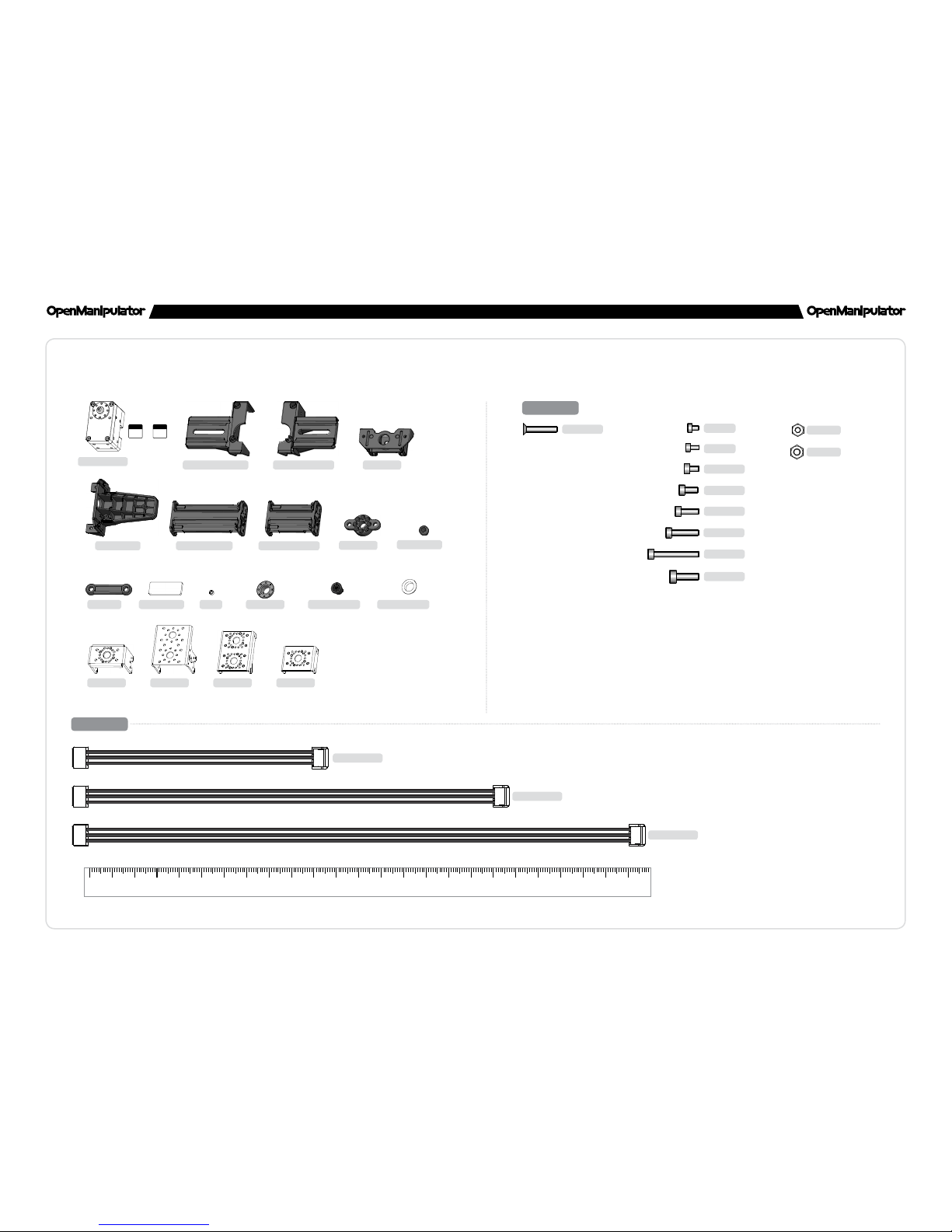
2 3
ASSEMBLY MANUAL ASSEMBLY MANUAL
2
CAUTION
1. Please read the assembly manual carefully.
2. Please check DYNAMIXEL IDs and lengths of cables, and assemble
DYNAMIXELs.
3. Please conrm the directions of DYNAMIXELs and the gripper are correct.
ID
11
CABLE-240
[DYNAMIXEL
ID
11
,
ID
15
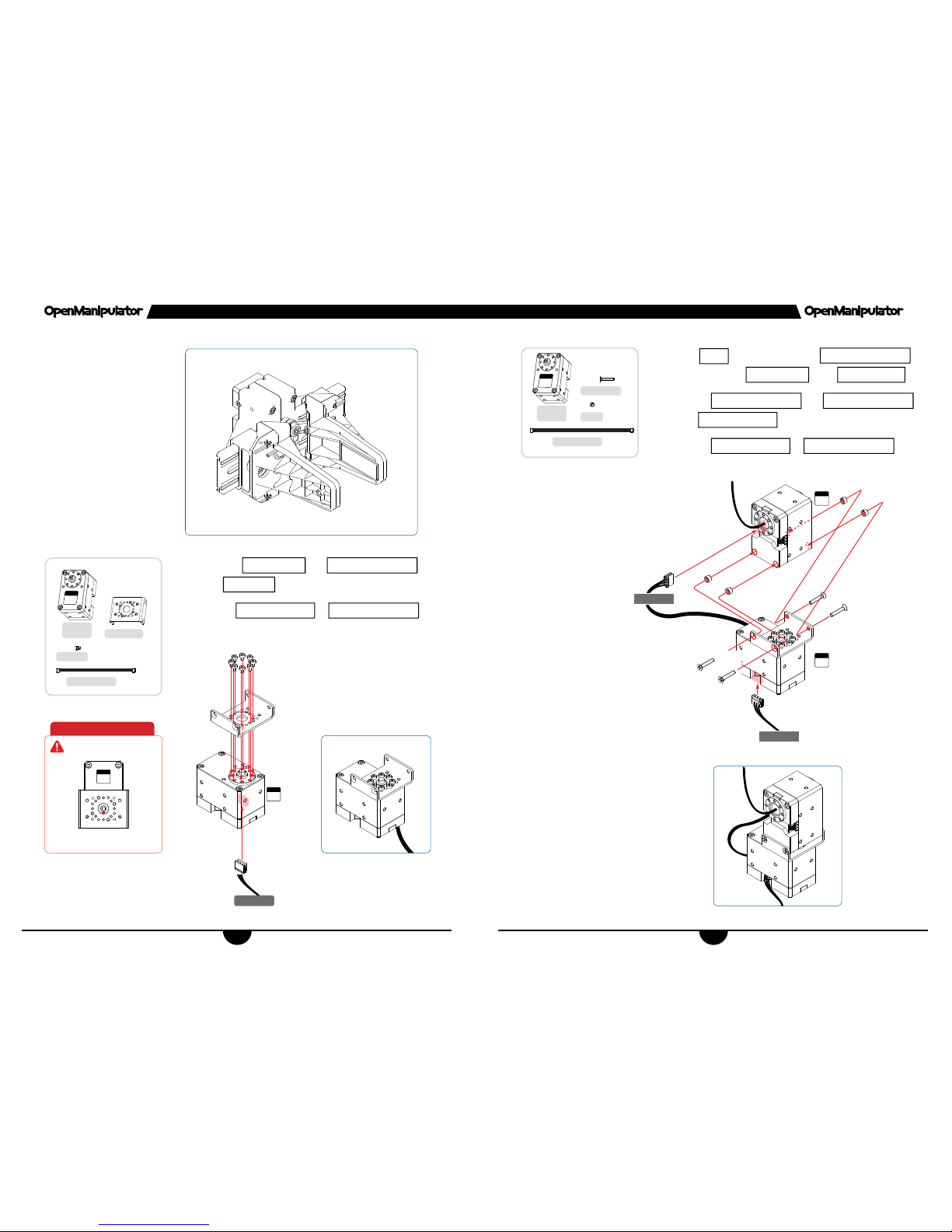
] Remove described bolts.
[DYNAMIXEL
ID
12
,
ID
13
,
ID
14
] Pass the cable through hollow back case, DC12-IDLER,
DC12-IDLER-CAP and DC12-P-BEARING and connect it into DYNAMIXEL.
DYNAMIXEL Preparations (XM430-W350-T)
ID
12
ID
14
CABLE-100
ID
13
CABLE-180
ID
15
XM430W250T
×5
DC12-IDLER
-CAP
×3
DC12-IDLER
×3
DC12-PBEARING
×3
CABLE-X3P-180
×1
CABLE-X3P-100
×1
CABLE-X3P-240
×1

4 5
ASSEMBLY MANUAL ASSEMBLY MANUAL
4
1
2
3
PALM GRIPPER
×2
RUBBER PAD
×2
x2
x2
CRANK ARM×1NUT-M3
×2
RAIL BLOCK×2LINK ROD
×2
FLANGE BUSH×2NUT-M3
×2
WB-M3×10
×2
4
x2
WB-M2.5×8×8NUT-M2.5
×8
Insert
NUT-M3
from underneath the
CRANK ARM
Assemble
LINK ROD
+
RAIL BLOCK
and
PALM GRIPPER
using
WB-M2.5x8
and
NUT-M2.5
Attach
RUBBER PAD
to the inner side of the
PALM GRIPPER
Assemble
LINK ROD
in the middle of the
RAIL BLOCK
using
FLANGE BUSH
and
WB-M3x10

6 7
ASSEMBLY MANUAL ASSEMBLY MANUAL
6
5
ID
15
RAIL BRACKET(LEFT)
×1
RAIL BRACKET(RIGHT)
×1
X-SP
×4
WB-M2.5×4
×4
WB-M2.5×12
×4
WB-M2×4
×4
6
FLANGE BUSH
×1
WB-M3×10
×1
7
FLANGE BUSH
×1
WB-M3×10
×1
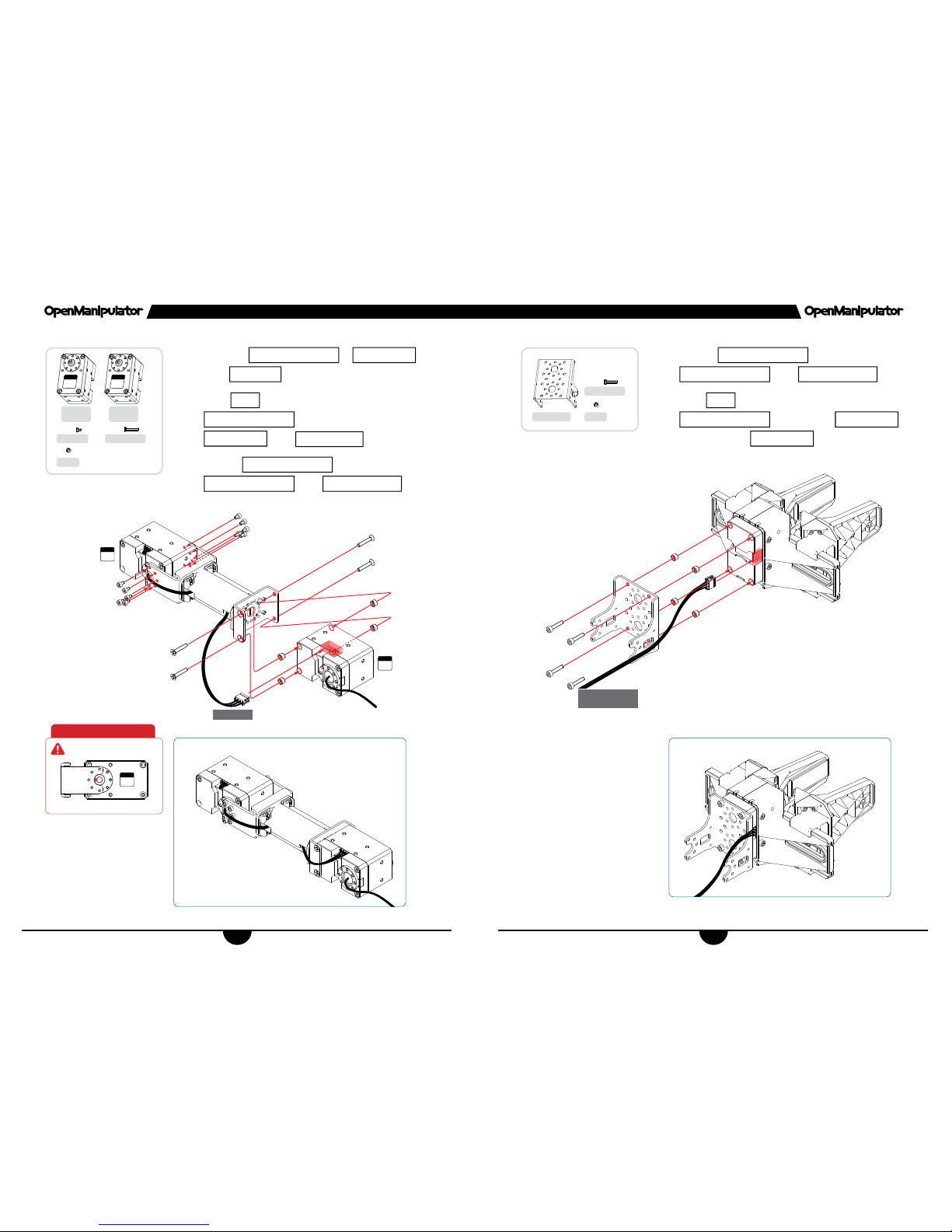
Assemble
RAIL BRACKET(RIGHT)
to
RAIL BRACKET(LEFT)
Assemble
DYNAMIXEL(ID 15)
to
RAIL BRACKET(RIGHT)
+
RAIL BRACKET(LEFT)
using
WB-M2.5x12
and
WB-M2.5x4
Assemble
CRANK ARM
to the horn of
DYNAMIXEL(ID 15)
using
WB-M2x4
Slide
LINK ROD
+
RAIL BLOCK
+
PALM GRIPPER
into
RAIL BRACKET
Assemble
FLANGE BUSH
to
CRANK ARM
and
LINK ROD
using
WB-M3x10
Horn Align Marking View
ID
15
CRANK ARM
CRANK ARM
FLANGE BUSH
XM430W350T
×1
ID
15
8 9
ASSEMBLY MANUAL ASSEMBLY MANUAL
8
8
CABLE-180
FR12-S102K
×1
ID
11
ID
11
WB-M2×3
×8
CABLE-X3P-180
×1
9
FHS-M2.5×14
×4
CABLE-180
CABLE-240
ID
12
ID
11
CABLE-X3P-240
×1
X-SP
×4
Assemble
FR12-S102K
and
DYNAMIXEL(ID 11)
using
WB-M2x3
Connect
CABLE-X3P-180
to
DYNAMIXEL(ID 11)
Insert
X-SP
into the bolt holes of
DYNAMIXEL(ID 12)
and assemble to
FR12-S102K
using
FHS-M2.5x14
Connect
DYNAMIXEL(ID 12)
and
DYNAMIXEL(ID 11)
using
CABLE-X3P-180
Connect
CABLE-X3P-240
to
DYNAMIXEL(ID 11)
Horn Align Marking View
XM430W350T
×1
ID
11
XM430W350T
×1
ID
12

10 11
ASSEMBLY MANUAL ASSEMBLY MANUAL
10
10
FR12-H101K×1FR12-S101K
×1
LINK FRAME(LONG)
×1
CABLE-240
(DYNAMIXEL ID12)
CABLE-180
(DYNAMIXEL ID13)
WB-M2.5×6
×4
NUT-M2.5
×4
WB-M2.5×8
×4
11
FR12-S102K
×1
FR12-H101K
×1
LINK FRAME(SHORT)
×1
WB-M2.5×6
×4
NUT-M2.5
×4
WB-M2.5×8
×4
Pass
CABLE-X3P-240
from
DYNAMIXEL(ID 12)
through the hole of
LINK FRAME(LONG)
Assemble
FR12-H101K
to
LINK FRAME(LONG)
using
WB-M2.5x8
and
NUT-M2.5
Assemble
LINK FRAME(LONG)
to
FR12-S101K
using
WB-M2.5x6
Pass
CABLE-X3P-180
from
DYNAMIXEL(ID 13)
through the hole of
LINK FRAME(SHORT)
Assemble
FR12-H101K
to
LINK FRAME(SHORT)
using
WB-M2.5x8
and
NUT-M2.5
Assemble
LINK FRAME(SHORT)
to
FR12-S102K
to using
WB-M2.5x6
12 13
ASSEMBLY MANUAL ASSEMBLY MANUAL
12
12
ID
14
ID
13
CABLE-180
WB-M2×3
×10
FHS-M2.5×14
×4
13
FR12-H104K
×1
WB-M2.5×12
×4
X-SP
×4
X-SP
×4
Assemble
DYNAMIXEL(ID 13)
to
FR12-H101K
using
WB-M2x3
Insert
X-SP
into the bolt holes of
DYNAMIXEL(ID 14)
and assemble to
FR12-S102K
using
FHS-M2.5x14
Connect
DYNAMIXEL(ID 13)
and
DYNAMIXEL(ID 14)
using
CABLE-X3P-180
Connect
DYNAMIXEL(ID 14)
and
DYNAMIXEL(ID 15)
using
CABLE-X3P-100
Insert
X-SP
into the bolt holes of
DYNAMIXEL(ID 15)
and assemble
FR12-H104K
to Gripper using
WB-M2.5x12
Horn Align Marking View
ID
13
XM430-
W350T
×1
ID
13
XM430W350T
×1
ID
14
CABLE-100
(DYNAMIXEL ID14)
14 15
ASSEMBLY MANUAL ASSEMBLY MANUAL
14
14
WB-M2×3
×10
15
CABLE-240
WB-M2×3
×10
FHS-M2.5×14
×4
X-SP
×4
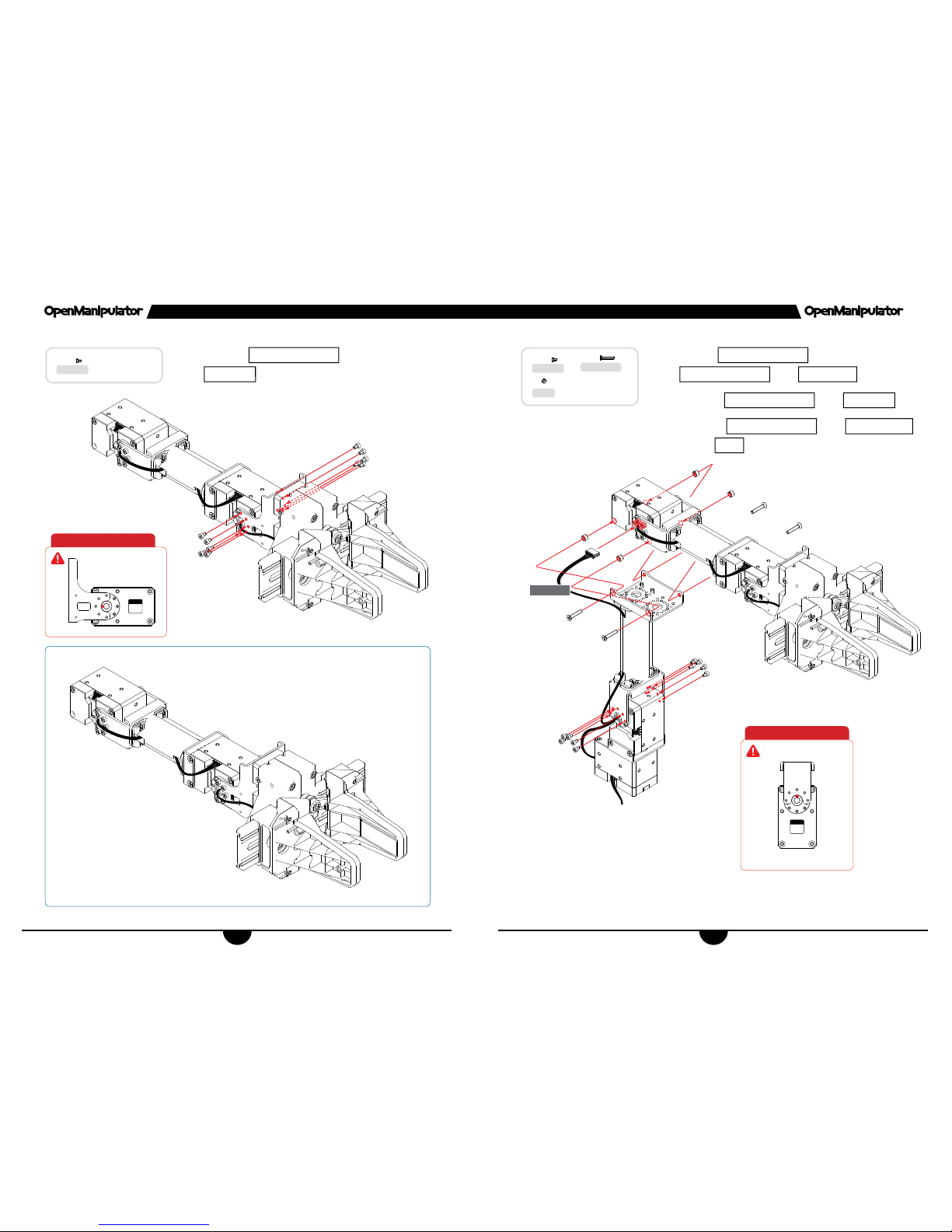
Assemble
DYNAMIXEL(ID 14)
and Gripper using
WB-M2x3
Connect
DYNAMIXEL(ID 12)
and
DYNAMIXEL(ID 13)
using
CABLE-180
Assemble
DYNAMIXEL(ID 12)
using
WB-M2x3
Assemble
DYNAMIXEL(ID 13)
using
FHS-M2.5x14
through
X-SP
Horn Align Marking View
Horn Align Marking View
ID
14
ID
12

16 17
ASSEMBLY MANUAL ASSEMBLY MANUAL
16
WB-M2.5×20×4X-SP
×4
Assemble
DYNAMIXEL(ID 11)
and
Base Plate-02
using
WB-M2.5x20
Appendix 1
Horn Align Marking View
ID
11
18
ASSEMBLY MANUAL
18
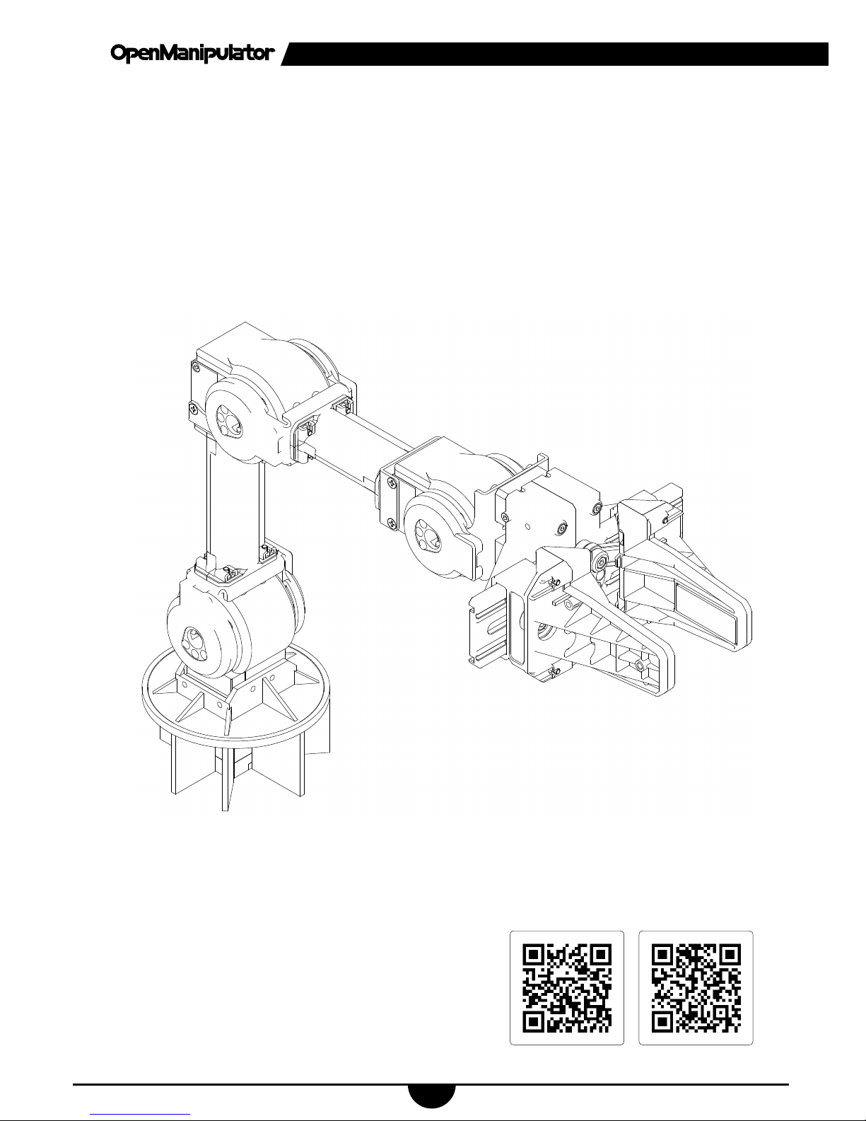
To prevent substance from getting caught between the DYNAMIXEL and frame,
3D printed optional parts can be attached to OpenManipulator. These parts can be downloaded from Thingiverse or Onshape. Please check the QR codes below.
Appendix 2
OnshapeThingiverse
ASSEMBLY MANUAL ASSEMBLY MANUAL
1:1
FHS-M2.5×14
×12
WB-M2.5×12
×8
WB-M2×4
×4
WB-M2×3
×38
WB-M2.5×20
×4
WB-M2.5×6
×8
WB-M2.5×4
×4
WB-M2.5×8
×16
WB-M3×10
×4
NUT-M2.5
×16
NUT-M3
×4
XM430-W350-T
×5
1:1
012345678910 11 12 13 14 15 16 17 18 19 20 21 22 23 24
ID11ID
15
~
CABLE-X3P-100
×1
CABLE-X3P-180
×2
CABLE-X3P-240
×2
RAIL BLOCK
×2
RAIL BRACKET(LEFT)
×1
RAIL BRACKET(RIGHT)
×1
PALM GRIPPER
×2
LINK FRAME(LONG)
×1
LINK FRAME(SHORT)
×1
FR12-H101K
×2
FR12-H104K
×1
FR12-S101K
×1
FR12-S102K
×2
CRANK ARM
×1
FLANGE BUSH
×4
LINK ROD
×2
RUBBER PAD
×2
Parts List
X-SP
×24
DC12-IDLER-CAP
×3
DC12-IDLER
×3
DC12-P-BEARING
×3

4
ASSEMBLY MANUAL
ALL RIGHTS RESERVED.
Copyright ⓒ by ROBOTIS Co., Ltd.
Reproduction and modication of this book in any form or by any
means is strictly prohibited without the prior consent or the written
permission from the publisher.
Contents and color may vary from those illustrated.
 Loading...