


Wrist Camera Vision System for CB-Series
Universal Robots
Instruction Manual
Get the latest version of the manual at support.robotiq.com
Original Notice

Wrist Camera Instruction Manual
Table of Contents
1. General Presentation 5
2. Safety 10
2.1. Warning 10
2.2. Intended Use 12
3. Installation 13
3.1. Scope of Delivery 14
3.1.1. Wrist Camera Kit for Universal Robots: 14
3.2. Required Tools and Equipment 15
3.3. Environmental and Operating Conditions 17
3.4. Mechanical Installation 18
3.4.1. Combo of 2-Finger Adaptive Gripper and Wrist Camera for Universal Robots 20
3.5. Electrical Setup 21
3.5.1. Power Supply 21
3.5.2. Cable Management 23
3.6. Software 23
3.6.1. Wrist Camera URCap Installation 24
3.6.1.1. Wrist Camera URCap Installation 24
3.6.2. Update and Uninstall 28
3.6.2.1. Version 1.1 and following 28
3.6.2.2. Version 1.0.2 and previous 30
4. Snapshot Position 31
4.1. Guidelines on Snapshot Position 33
4.2. Snapshot Position Wizard 34
4.3. Copy a Calibration 38
5. Object Teaching 39
5.1. Guidelines on Object Teaching 40
5.2. Teach Object Wizard 42
5.2.1. Automatic Method 44
5.2.1.1. Select Calibration 44
5.2.1.2. Select Model 45
5.2.1.3. Edit Model 56
5.2.1.4. Refine Model 61
5.2.1.5. Validate Model 62
5.2.1.6. Scan Model 63
5.2.2. Parametric Method 64
5.2.2.1. Circle 65
5.2.2.2. Ring 66
5.2.2.3. Rectangle 66
5.2.2.4. Square 67
5.2.3. Configure Model 68
5.2.3.1. Multiple objects detection 70
©Robotiq inc. 2016-2018
2

Wrist Camera Instruction Manual
5.2.3.2. Color Validation 71
5.2.3.3. Detection thresholds and scores 76
5.2.3.4. Camera settings 81
5.2.3.5. Save location 81
6. Programming with the Camera Locate Node 82
6.1. Linear Move with Feature – Pick and Place Template 85
6.2. object_location pose 86
6.3. Edit Detection Threshold and Object Location 89
6.4. Camera Locate node at a variable Snapshot position 90
7. Specifications 92
7.1. Mechanical Specifications of Wrist Camera 93
7.1.1. Center of Mass and Moment of Inertia 94
7.2. Electrical rating & performance of Wrist Camera 96
7.3. Vision System Specifications 97
8. Maintenance 101
9. Spare Parts, Kits and Accessories 102
10. Troubleshooting 103
10.1. LED status 104
11. Warranty andPatent 105
12. Contact 107
A. Harmonized Standards, Declarations and Certificates DD
A1. Declaration of Incorporation DD
©Robotiq inc. 2016-2018
3

Wrist Camera Instruction Manual
Revisions
Robotiq may modify this product without notice, when necessary, due to product improvements, modifications or changes
in specifications. If such modification is made, the manual will also be revised, see revision information. See the latest
version of this manual online at: support.robotiq.com.
2018-09-10
Updated section 3, 5 and 6 according to the PolyScope version of the user (CB-Series vs. e-Series).
Updated section 5 and all pertaining subsections; major changes to the Teach object wizard (color validation layer masks,
multiple object detection, e-Series support).
2018-05-01
Updated section 5 and all pertaining subsections; major changes to the Teach object wizard
2018-03-26
Updated Section 3.6.2 for Update and uninstall
2017-06-07
Updated Section 3.6 for URCap package installation procedure
Updated Section 4.2 for calibration process
Updated Sections 5.2, 5.2.1, 5.2.2, 5.2.3 for new and improved teaching methods.
Added Section 6.2 to use advanced programming with the vision system.
Updated technical specifications (Section 7.3).
Updated calibration board for UR5 and UR10 robots (Section 4)
2016-11-16
Updated specifications (section 6)
Updated installations instructions (section 4)
Added Troubleshooting instructions (section 9.1)
2016-08-26
First release
©Robotiq inc. 2016-2018
4

Wrist Camera Instruction Manual
1. General Presentation
The terms "Camera" and "Wrist Camera" used in the following manual all refer to the Robotiq Wrist Camera, while the
term "Vision" and "Vision System" used in the following manual all refer to the Robotiq Wrist Camera Vision System for
Universal Robots.
The Vision System uses the Robotiq Wrist Camera and the Camera Locate software on Universal Robots to provide you
with a simple object teaching interface.
The interface allows to set up the Vision System so it can recognize object locations and orientations automatically. The
Vision System, using the Camera Locate feature, is only designed to locate one object at the time on a predefined
workplane. It gets the object's position (x, y) and orientation along the z-axis. It allows to operate the robot according to the
object location. The Camera is designed to work in industrial applications in combination with the Robotiq 2-Finger
Adaptive Gripper.
Note
The following manual uses the metric system. Unless specified, all dimensions are in millimeters.
Note
The following section presents the key features of the Vision System and must not be considered as appropriate
to complete operation, each feature is detailed in the appropriate section of the manual. Safety guidelines must
be read and understood before any operation is attempted with the system.
Vision System components:
The figure below describes the various components of the Robotiq Vision System for Universal Robots. This system will
use the Robotiq Wrist Camera, mounted on any of the Universal Robots (UR3, UR5, UR10) using a CB3.1 controller or
greater. For a list of provided components with your Robotiq Wrist Camera kit for UR, please refer to the Scope of Delivery
section.
Caution
Robotiq Vision System is only compatible with Universal Robots with controller version CB3 and later, to identify
your controller, please contact your Universal Robots representative.
©Robotiq inc. 2016-2018
5

Wrist Camera Instruction Manual
Fig. 1-1: Schematic representation of the Robotiq Wrist Camera Vision System hardware.
l Robotiq Wrist Camera: Described in details in sub-section Wrist Camera below.
l End effector: Any tool mounted on the robot for its application, the Wrist Camera is meant for direct integration of the
Robotiq 2-Finger Adaptive Gripper.
l Universal Robot Arm: Any of the UR3, UR5 or UR10 model from Universal Robots.
l Universal Robot Controller: Controller model CB3 from Universal Robots.
©Robotiq inc. 2016-2018
6

Wrist Camera Instruction Manual
Snapshot Position & Workspace:
The figure below illustrates the various terms used in the following manual to describe the Vision System's Snapshot
Position and workspace. The object location process will always start at the Snapshot Position, that position will determine
the field of view of the Camera and thus the workspace. See the Snapshot Position section for details on how to teach the
Snapshot Position.
Fig. 1-2: Schematic representation of the Robotiq Vision System Snapshot Position and workspace concepts.
l Snapshot Position: the robot pose use to take snapshots from the Wrist Camera.
l Workspace: the area of interest for the Vision System,it is defined by the Camera's field of view.
l Object: the object you want to locate using the Vision System.
l Calibration board: a grid provided with your Camera UR Kit used during the calibration process of the Snapshot
Position.
©Robotiq inc. 2016-2018
7

Wrist Camera Instruction Manual
Object Location:
The System will use the Camera Locate node described in the Programming with the Camera Locate Node section to
locate the object. The figure below represents the object location process. Please refer to the Programming with the
Camera Locate Node section for details on the object location process.
Fig. 1-3: Object location process schematic representation.
l Object to locate: The object you want to locate with coordinates X & Y and rotation Rz.
l Camera Locate relative frame: The reference frame updated by the Vision System to provide you with the
objectlocation.
l Robot base frame: The reference frame of the Universal Robot. Coordinate [0,0,0].
©Robotiq inc. 2016-2018
8

Wrist Camera Instruction Manual
Wrist Camera:
The hardware at the center of the Vision System is the Robotiq Wrist Camera illustrated in the figure below. Steps on how
to install the Wrist Camera are explained in the Installation section.
Fig. 1-4: Main features of the Wrist Camera.
Main features of the Robotiq Wrist Camera:
l CMOS image sensor with liquid lens:
l Resolution: 0.3 to 5 Mpx;
l Frame rate: 2 to 30 FPS;
l Focus from 70 mm to infinity, automatic control.
l 2 sets of 3 LEDs:
l Integrated lighting with automatic control.
l Single high-flex 10 meter pigtail cable:
l USB 2.0;
l 24V DC power.
l ISO 9409-1-50-4M6 bolt pattern, both sides:
l Direct mounting on the UR;
l Direct mounting of the 2-Finger Adaptive Gripper on the Camera.
Info
The Robotiq Wrist Camera provides a direct mounting interface for the Robotiq 2-Finger Adaptive Gripper,
providing a mechanical interface, 24V power and communication to the Gripper.
©Robotiq inc. 2016-2018
9

Wrist Camera Instruction Manual
2. Safety
Warning
The operator must have read and understood all of the instructions in the following manual before handling the
Robotiq Wrist Camera Vision System for Universal Robots.
The term "operator" refers to anyone responsible for any of the following operations on the Wrist Camera Vision
System:
l Installation
l Control
l Maintenance
l Inspection
l Calibration
l Programming
l Decommissioning
This documentation explains the various components of the Vision System, as well as general operations regarding the
whole life-cycle of the product from installation to operation and decommissioning.
The drawings and photos in this documentation are representative examples and differences may exist between them and
the delivered product.
2.1. Warning
Note
Any use of the Vision System in noncompliance of these warnings is inappropriate and may cause injury or
damage.
Warning
The Wrist Camera Vision System used in human-robot collaboration must not be considered a complete safety
measure, additional dedicated safety device(s) must be considered. Vision System failure can occur and result in
danger for workers or machinery if not properly secured. See local or international safety measure for humanrobot collaboration.
Warning
©Robotiq inc. 2016-2018
10

Wrist Camera Instruction Manual
l The Camera needs to be properly secured before operating the robot.
l Do not install or operate a Camera that is damaged or lacking parts.
l Never supply the Camera with an alternative current.
l Make sure all cord sets are always secured at both ends, at the Camera and at the robot.
l Always respect the recommended keying for electrical connections.
l Be sure no one is in the robot and/or Camera path before initializing the robot's routine.
l Always respect the Camera payload.
l All local safety measures and/or laws on robot operation must be applied to the Vision System.
l
Avoid looking straight at the LEDs when they are turned on as this may cause dazzlement.
Any use of the Vision System in noncompliance with these warnings is inappropriate and may cause injury
ordamage.
©Robotiq inc. 2016-2018
11

Wrist Camera Instruction Manual
2.2. Intended Use
The Vision System is designed to locate objects laying flat on the defined workspace. The system can identify and locate
multiple kind of objects, each object will require its own object teaching process as explained in the Object Teaching
section. The Vision System gets the object's position (x, y) and orientation along the z axis. It allows to operate the robot
according to the object location.
Tip
The Guidelines on Snapshot Position section will give you advice on what workspace should be used or avoided.
Section 5 will give you advice on what objects can be located or not along with background recommendations.
Caution
The Vision System is NOT intended for:
l Metrology
l Bar-code / QR code reading
Note
Always comply with local and/or national laws, regulations and directives on automation safety and general
machine safety.
The unit may be used only within the range of its technical specifications. Any other use of the product is deemed improper
and unintended use. Robotiq will not be liable for any damages resulting from any improper or unintended use.
©Robotiq inc. 2016-2018
12

Wrist Camera Instruction Manual
3. Installation
The following subsections will guide you through the installation and general setup of your Robotiq Wrist Camera
Vision System:
l Section 3.1 details the scope of delivery for the Wrist Camera kit for UR, verify your package.
l Section 3.2 lists the required tools, parts and equipment for proper use of your Camera.
l Section 3.3 explains the operating conditions that must be met for the 2-Finger Gripper to operate normally.
l Section 3.4 guides you through the mechanical installation using the Wrist Camera and other optional parts.
l Section 3.5 describes the required electrical set up of the Gripper, its power source and cable management.
l Section 3.6 guides you through the software installation.
Warning
Before installing :
l Read and understand the safety instructions related to the Vision System.
l Verify your package according to the scope of delivery and your order.
l Have the required parts, equipment and tools listed in the requirements ready.
Warning
When installing :
l Meet the environmental conditions.
l Do not operate the Vision System, or even turn on the power supply, before the Camera is firmly
anchored and the danger zone iscleared.
©Robotiq inc. 2016-2018
13

3.1. Scope of Delivery
3.1.1. Wrist Camera Kit for Universal Robots:
RWC-UR-KIT
Standard upon delivery:
l Robotiq Wrist Camera with 10m High-Flex pigtail cable RWC-CAM-001;
l Universal Robots pattern tool plate RWC-TOOL-062;
l 16 Gb USB stick ACC-USB-16G;
l USB software license dongle ACC-USB-DONGLE;
l 4-port USB hub ACC-USB-4-HUB;
l Calibration board ACC-CALIB-BOARD;
l Colored background for object teaching ACC-TEACH-BACK;
l Hardware kit for fixing Wrist Camera on Universal Robots.
Wrist Camera Instruction Manual
Caut ion
The hardware for fixing a tool on the Wrist Camera is not provided.
Combo of 2-Finger Adaptive Gripper and Wrist Camera for Universal Robots:
CUR-AGC-085-RWC or CUR-AGC-140-RWC
Standard upon delivery:
l Wrist Camera Kit for Universal Robots includes:
l Robotiq Wrist Camera with 10m High-Flex pigtail cable RWC-CAM-001;
l 16 Gb USB stick ACC-USB-16G;
l USB software license dongle ACC-USB-DONGLE;
l 4-port USB hub ACC-USB-4-HUB;
l Calibration board ACC-CALIB-BOARD;
l Colored background for object teaching ACC-TEACH-BACK;
l Hardware kit for fastening Wrist Camera to Universal Robots.
l Gripper parts:
l Basic Gripper unit (85 or 140) AGC-GRP-002 or -140 (depending on your combo);
l Screw kit for fixing Gripper on Wrist Camera.
©Robotiq inc. 2016-2018
14

3.2. Required Tools and Equipment
The following tools are required to install the Wrist Camera:
l 2 mm slotted screwdriver to perform terminal block connections when wiring.
Provided tools with the Wrist Camera:
l 4 mm hex key to mount the Camera on the UR arm.
Optional tools if installing 2-Finger combo: CUR-AGC-085-RWC or CUR-AGC-140-RWC:
l none, use the provided 4 mm hex key.
The following parts are required for setup:
l Universal Robots UR3, UR5 or UR10 along with its controller;
Wrist Camera Instruction Manual
Warning
The system is only compatible with UR CB3.1 controller, check your controller version.
l Universal Robots' PolyScope version must be 3.5 or later in order to install the URCap.
l Power supply if not using Universal Robots controller supply (see below);
l Fuse, see information below.
The Camera needs to be supplied by a DC voltage source. This power supply is not included with the Camera kit for
UR. Required power supply must match the Robotiq device. The following table shows the specifications with
regards to the power supply required to operate the Camera and the optional RobotiqGripper.
SPECIFICATION VALUE
Output voltage 24 V DC ±10%
Output current 1 A
Overcurrent Recommended power supply with internal
protection, otherwise fusing is required.
2 A fuse at 25°C [77°F]
1
Info
1
Suggested fuse is a: Phoenix Contact # 0916605 2 A thermal; use AWG #20 wiring.
©Robotiq inc. 2016-2018
Table 3 - 1: Robotiq Wrist Camera and 2-Finger power supply requirements.
15

Wrist Camera Instruction Manual
Warning
If your power supply exceeds the specified regulation, over-voltage protection is required.
Robotiq recommends the use of the following power supplies:
l For the 1A output current: TDK-Lambda DPP Series, 100W Single Output DIN Rail Mount Power Supply: DPP30-
24.
©Robotiq inc. 2016-2018
16

Wrist Camera Instruction Manual
3.3. Environmental and Operating Conditions
The Wrist Camera is designed for industrial applications. Always respect the following specified operating
environmentalconditions:
CONDITION VALUE
Minimum storage/transit
temperature
Maximum storage/transit
temperature
Minimum operating temperature 0°C [32°F]
Maximum operating temperature 50°C [122°F]
Humidity (non-condensing) Non-condensing.
Others Lenses must be free from dust, soot and water.
Environment must be free from powerful electromagnetic
interference.
Environment must be free from corrosive or explosive liquids or
gases.
Table 3 - 2: Environmental and operating conditions for the Wrist Camera.
-30°C [-22°F]
70°C [158°F]
©Robotiq inc. 2016-2018
17

Wrist Camera Instruction Manual
3.4. Mechanical Installation
Wrist Camera kit for Universal Robots
For mechanical installation of a Wrist Camera on a UR robot along with an end-effector (other than Robotiq's 2Finger Gripper), follow these instructions and refer to the figure below:
l Place the Wrist Camera (RWC-CAM-001) on the robot arm. Align the camera's indexing (dowel) pin properly in
Universal Robots' bolt pattern.
l Place the tool plate (RWC-TOOL-062) on the camera. Align the tool plate's indexing (dowel) pin correctly in the
Wrist Camera.
l Fix the desired end-effector on the robot arm, through the tool plate and the camera, using M6 screws.
l Fix the cable along the robot arm, please refer to the Cable Management section.
The end-effector is not screwed in the camera or the tool plate, but directly in the robot arm. Both camera
and tool plate have through holes for thisassembly.
Warning
Make sure the Camera is oriented properly.
Do not offset the Camera from the tool center point on the X and Y axes, or around the Z axis.
©Robotiq inc. 2016-2018
Fig. 3-1: Mechanical installation of the Wrist Camera kit for Universal Robots.
18

Wrist Camera Instruction Manual
Hardware
M6 screws to mount an end-effector on the Wrist Camera are not provided. Use M6 screws of appropriate
length to secure the end-effector on the robot arm.
©Robotiq inc. 2016-2018
19

Wrist Camera Instruction Manual
3.4.1. Combo of 2-Finger Adaptive Gripper and Wrist Camera for Universal Robots
For mechanical installation of a Wrist Camera on a UR robot along with Robotiq's 2-Finger Gripper, follow these
instructions, and refer to the figure below:
l Place the Wrist Camera (RWC-CAM-001) on the robot arm. Align the camera's indexing (dowel) pin properly in
Universal Robots' bolt pattern.
l Fix the camera on the robot arm using the provided M6 X 12 LHCS screws and lock washers.
When mounting only the Wrist Camera on the robot, the spring pins that would ensure connection to a
Robotiq 2-Finger Gripper are exposed. Be careful not to harm them.
l Mount the gripper directly on the Wrist Camera using the provided M5 X 35 SHCS and lock washers.
l Fix the cable along the robot arm; please refer to the Cable Management section.
Fig. 3-2: Mechanical installation of the Combo of 2-Finger Gripper and Wrist Camera for Universal Robots.
©Robotiq inc. 2016-2018
20

Wrist Camera Instruction Manual
3.5. Electrical Setup
3.5.1. Power Supply
Caution
If mounting a 2-Finger Gripper on the Wrist Camera, the Camera replaces the gripper's coupling. Therefore,
only the Wrist Camera's device cable is required to provide power and communication to both the camera
and the gripper. The wiring for setups including only the camera or both the camera and the gripper is the
same.
Power and communication are established with the Wrist Camera via the high-flex device cable. The cable provides a
24V power supply to the Wrist Camera and enables USB 2.0 communication with the Universal Robots controller.
Follow these steps to correctly wire the Wrist Camera (or the camera and 2-Finger Gripper combo) to a Universal
Robots controller :
l With the controller turned off, connect the red (24V) and black (0V) wires of the device cable as shown in the figure
below. Use any available 24V and0V.
Fig. 3-3: Power supply wiring on CB3.1 Universal Robots controller.
l Connect the 4-port USB hub (ACC-USB-4-HUB) inside the robot controller.
l Connect the Wrist Camera's USB connector in the 4-port USB hub.
l Connect the license USB dongle (ACC-USB-DONGLE) in the 4-port USB hub.
Fig. 3-4: 4-port USB hub connection.
©Robotiq inc. 2016-2018
21

Wrist Camera Instruction Manual
Wrist Camera grounding is optional and is done via the robot ground. The camera's indexing pin (dowel) is the
groundconnector.
©Robotiq inc. 2016-2018
22

Wrist Camera Instruction Manual
3.5.2. Cable Management
Warning
Use proper cabling management. Be sure to have enough forgiveness in the cabling to allow movement of
the Gripper along all axes without pulling out the connectors. Always protect the controller side of the cable
connection with a strain relief cable clamp.
3.6. Software
Make sure the Wrist Camera is properly mounted on the robot arm and that all electrical wiring is correctly done (refer
to the Mechanical Installation section and the Electrical Setup section). Make sure your Universal Robots software is
up to date. PolyScope must be version 3.3 or later in order to install aURCap.
l Refer to the Wrist Camera URCap Installation section for the installation procedure.
l Refer to the Update and Uninstall section to update the version or uninstall.
Do not unplug the 16 Gb USB stick or the USB license dongle, even after the installation has been
completed.
Center of mass
Prior to use over Universal Robots, adjust the center of mass and payload from the Installation tab (refer to
the Mechanical Specifications of Wrist Camera section).
©Robotiq inc. 2016-2018
23

Wrist Camera Instruction Manual
3.6.1. Wrist Camera URCap Installation
Make sure the Wrist Camera is properly mounted to the robot arm and that all electrical wiring is correctly done (refer
to the Mechanical Installation section and the Electrical Setup section). Make sure your Universal Robots software is
up to date. The URCap pertaining to this product version has been tested in PolyScope 3.5.
Update
For the URCap update, refer to the Update and Uninstall section.
3.6.1.1. Wrist Camera URCap Installation
l From support.robotiq.com,visit the vision system page and download the latest UCC-X.X.X compressed file.
l Decompress the content of the latest UCC-X.X.X compressed file on the provided 16 Gb USB stick (ACC-USB-
16G).
l Make sure the .urcap file and the vision system folder are on the root of the USB drive, as shown in the figure
below.
Fig. 3-5: Files at the root of the 16 Gb USB stick.
l With the robot controller ON, insert the 16 Gb USB stick containing the latest URCap and vision server in the 4-
port USB hub.
Fig. 3-6: Connections on the 4-port USB hub.
©Robotiq inc. 2016-2018
24

PolyScope 3.6
l From PolyScope's home page, tap Setup Robot and go to URCaps Setup.
l Tap the plus ( + ) sign and open Robotiq_Wrist_Camera-X.X.X.urcap from the USB stick.
l Tap Restart and wait for PolyScope to reopen.
l Go to Program Robot and then to the Installation tab.
l Choose Camera and go to the Dashboard tab.
l Verify the Vision system's status.
Wrist Camera Instruction Manual
l Tap Install and wait for the vision server to be installed.
l If the firmware has to be updated, tap Upgrade Camera firmware to upgrade it before continuing (refer to the
figure below).
©Robotiq inc. 2016-2018
Fig. 3-7: Camera dashboard ready to install the vision server.
25

Wrist Camera Instruction Manual
Fig. 3-8: Camera dashboard with camera firmware upgrade.
l Wait for the vision system to start.
l The installation is completed.
l In order to use another USB drive on the controller, reboot the robot controller.
Do not unplug the 16 Gb USB stick or the USB license dongle, even after the installation has been
completed.
Dashboard
The Dashboard tab contains helpful information for troubleshooting the vision system.
Test the Installation
After the installation has been completed, verify that the vision system works properly.
©Robotiq inc. 2016-2018
26

Wrist Camera Instruction Manual
PolyScope 3.6
1. From a robot program, go to the Installation tab and choose Camera.
2. Go to the Dashboard tab and verify the system's status. Make sure the vision system is running.
3. Go to the Camera tab. The output image will appear.
Center of Mass
Prior to use over Universal Robots, adjust the center of mass and payload from the Installation tab (refer to
the Mechanical Specifications of Wrist Camera section).
©Robotiq inc. 2016-2018
27

Wrist Camera Instruction Manual
3.6.2. Update and Uninstall
Warning
Updating the Wrist Camera software, unplugging the USBstorage device and/or switching USBports must
always be done while the robot is initialized and running.
3.6.2.1. Version 1.1 and following
PolyScope 3.6
1. From a robot program, go to the Installation tab.
2. Tap on Camera and go to Dashboard.
3. Tap Stop camera.
4. Tap Uninstall.
5. Remove the 16 Gb USB stick containing the older URCap and vision server from the 4-port USBhub.
6. Go to Setup Robot.
7. Tap URCaps Setup.
8. In the Active URCaps text box, tap the Camera URCap.
9. The Camera URCap should be highlighted.
10. Tap the minus button (-) to uninstall the URCap.
11. Restart PolyScope to complete the uninstall process.
12. Turn off or reboot the controller.
13. Connect the 16 Gb USB stick containing the older URCap and vision server to a PC.
14. Format it using FAT32.
15. Follow the procedure from theWrist Camera URCap Installation section to install the newest software.
©Robotiq inc. 2016-2018
28

Wrist Camera Instruction Manual
©Robotiq inc. 2016-2018
29

Wrist Camera Instruction Manual
3.6.2.2. Version 1.0.2 and previous
1. On a blank USB stick, add the following file : urmagic_uninstall.sh .
2. From a Robot Program, go to the Installation tab. Choose Camera and go to the Camera tab.
3. Tap Stop camera to stop the Vision server.
4. With the controller on, insert the USB stick containing the urmagic file in the UR teach pendant. Automatic
uninstall will begin.
5. Wait for the uninstall to be completed. Remove the USB stick containing the urmagic file.
6. Remove the 16 Gb USB stick containing the vision server.
7. From the home page, go to Setup Robot.
8. Tap URCaps Setup.
9. In the Active URCaps text box, tap the Camera URCap.
10. The Camera URCap should be highlighted.
11. Tap the minus button (-) to uninstall the URCap.
12. Turn off or reboot the controller
13. Connect the 16 Gb USB stick to a PC.
14. Format it using FAT32.
15. Follow the procedure from theWrist Camera URCap Installation section to install the latest software.
©Robotiq inc. 2016-2018
30

Wrist Camera Instruction Manual
4. Snapshot Position
Prior to teaching object with the Camera Locate URCaps node (refer to the Programming with the Camera Locate Node
section), the operator must define a Snapshot Position using the SnapshotPosition wizard. The following section and sub-
sections will guide you through this process.
Requirements:
l You must have completed the installation steps of the Installation section.
l Robot must set up to reach the desired workspace.
l You must have the correct calibration board in hand.
Reminders:
l You can teach as many Snapshot Positions as you want.
l Snapshot Position is where the robot is positioned to search for objects.
l One Snapshot Position can be used to search many objects.
l When the object teaching process of the Object Teaching section is done, it is linked to the Snapshot Position and you
cannot change that position.
l Each Snapshot Position along with the workplane will define a workspace according to the field of view of the Camera.
Refer to theSpecifications section for details on the field of view.
Calibration Boards:
Tip
If you are viewing a printed version of this manual, please visit support.robotiq.com to download the file.
l For UR5 and UR10
Along with your kit you will have the calibration board used for UR5 and UR10 on one side of the board, part number
ACC-CALIB-BOARD.
If you lose or damage your board, you can print the following file:
Note
If you are viewing the PDF version of the manual, please visit the online version of this manual at
support.robotiq.com to get the calibration board files. If you have printed this manual, please stop doing so, save
some trees and visit the website.
Info
UR5 and UR10 calibration board must be printed on Letter (11'' x 17'') or A3 paper, make sure scale is at 100%.
You can validate that your calibration board had the good scale by measuring the scale on your sheet.
l For UR3
©Robotiq inc. 2016-2018
31

Wrist Camera Instruction Manual
Along with your kit you will have the calibration board used for UR3 robots on one side the the board, part number
ACC-CALIB-BOARD. The color balance circles are not used yet with the vision system and are for future use. If you loose or
damage your board, you can print the following file:
Info
UR3 calibration board must be printed on Letter (8.5'' x 11'') or A4 paper, make sure scale is at 100%. You can
validate that your calibration board had the good scale by measuring the scale on your sheet.
©Robotiq inc. 2016-2018
32

Wrist Camera Instruction Manual
4.1. Guidelines on Snapshot Position
Caution
During the snapshot position definition, the ambient light must be of approximately 500 lux. At run-time, this
condition is not required.
The following must be considered when choosing your Snapshot Position:
l Choosing the workspace:
l Mostly uniform color;
l Planar;
l Provide contrast to your part; refer to theVision System Specifications section for details.
l Distance to the workplane:
l Your Snapshot Position will determine the field of view of the camera and thus the workspace used afterwards.
l See specifications in the Vision System Specifications section for details on the field of view & part size;
l Getting closer to the workplane, will reduce your workspace but allow you to locate smaller objects;
l Getting away from the workplace will increase the workspace but will increase the minimum size of objects to
locate.
Tip
During the Snapshot Position define step, use the "Show Grid" button, a grid will appear. Your
object should be larger than one grid cell.
l Angle of the camera:
l Snapshot position should consider the Camera angle:
l Robotiq greatly recommends to have the Camera perpendicular to the surface:
l Be as close as possible to perpendicular, avoid reflections.
l Object should be seen from the top view, not from the side.
l Calibration board:
l Snapshot position does not need to see the full calibration board, calibration step does.
Tip
The Snapshot position and Calibration pose are decoupled, they do not need to be the same.
l Use the appropriate calibration board.
l Board must be fully visible by the Camera.
l Refer to theVision System Specifications section for Calibration board position specifications.
©Robotiq inc. 2016-2018
33

Wrist Camera Instruction Manual
4.2. Snapshot Position Wizard
Feature Point:
Prior to defining the Snapshot Position, the operator must define a feature point.To do so, from the Universal Robots
Polyscope interface:
l Start a new program or open yours, then go to the Installation tab.
l Go to Features.
l Tap Point to insert a new point feature.
l Select that point, check the Variable checkbox.
l Define that point position anywhere by tapping Set this waypoint, then tap OK, actual position does not mater.
l Tap Rename to give a significant name to your feature, that name will be used as a reference frame later on in your
program.
Info
Each Snapshot Position you teach will require its own Feature point.
Snapshot Position Wizard:
Snapshot Position is define using the Snapshot Position Wizard, from the Universal Robots Polyscope interface, still within
the Installation tab:
l Go to Camera.
l Go to the Snapshot Positions tab.
l In the drop-down list, select the Feature you wish to use.
l Tap Define to launch the wizard.
Wizard step 1: Define Snapshot Position
l Move the robot arm using the Freedrive to place the Wrist Camera.
l Remember the guidelines from the Guidelines on Snapshot Position section:
l Distance will determine field of view and size of objects to be located.
l Use the Show Grid to help you choose distance (object at least one cell).
l Camera view should be quasi perpendicular to surface.
l Once the robot arm is in a proper position, tap Save position. Wizard will go to next step.
Wizard step 2: Calibrate
l Place the appropriate calibration board in the field of view of the camera
l Remember to use the appropriate board, according to your robot model
l The board orientation should match the screen - landscape orientation
©Robotiq inc. 2016-2018
34

l Make sure the Camera see the whole board
Tip
Snapshot Position will determine the field of view, notice that the calibration step position does not
have to be the same as Snapshot position. Thus, you can have a small field of view, then move back for
calibration step.
l Tap Calibrate to begin calibration
Warning
Calibration is an automatic process, the robot will move in order to perform calibration. Make sure the
robot workspace is clear. You can tap Cancel to stop the process. Operator should watch the robot at
all time and have emergency stop button at hand.
l The Vision System will center on the board and take 27 poses of the board.
l After the 27 poses, it will take 9 more photos for validating.
Wrist Camera Instruction Manual
l When the process is done, you will be asked to Accept or Re-Calibrate.
l Accept if the calibration board grid is match on all pose (first 27 poses)
l Re-Calibrate if the grid is not matched
l The wizard will show the 9 validating poses.
l Verify that the accuracy on the validation poses according to the color chart.
l Dark blue: local accuracy of +/-0mm.
l Dark red: local accuracy of +/-4mm and over.
©Robotiq inc. 2016-2018
Fig. 4-1: Validating poses.
35

Wrist Camera Instruction Manual
l If the accuracy is larger than +/- 4mm, an message will inform you that you should perform the calibration again.
l When you tap Accept, you will exit the wizard and the process is completed.
Once the calibration has been accepted, the Snapshot Position will appear in the Snapshot Positions tab with the name of
the Feature Point previously created. You can define other Snapshot positions, as long as you define new Feature Points.
To delete a Snapshot Position, tap the bin.
Tip
Make sure you save the Installation file (tap Load/Save from the Installation tab) in order to save the Snapshot
positions created.
©Robotiq inc. 2016-2018
36

Features
Wrist Camera Instruction Manual
Icon Feature Description
Define Launches the Snapshot Position definition wizard.
Show grid Displays a grid on the camera's field of view.
Meant to test the camera’s height relative to the workplane : a
part should be at least as large as a square of the grid.
Hide grid Hides the grid of the camera's field of view.
Save
position
Saves the robot position for the Snapshot Position.
This is the position from which the robot will do the part
detection.
Calibrate Starts the calibration procedure.
The robot will move automatically to defined positions for the
calibration.
Cancel Cancels the calibration procedure while it is running.
Re-calibrate Restarts the calibration procedure.
©Robotiq inc. 2016-2018
Accept Accepts the calibration process.
Delete Deletes a defined Snapshot position.
37

Wrist Camera Instruction Manual
4.3. Copy a Calibration
When defining a snapshot position, it is possible to copy the calibration from another snapshot position. This allows for a
faster snapshot position modification when using the same work plane.
Work Plane
To ensure proper precision, the work plane surface of both (new and copied) snapshot positions should be the
same.
To copy a calibration, you need to have a snapshot position already defined from which you want to copy the calibration.
l Create a new Snapshot feature point on the same plane as the existing Snapshot point you want to copy.
l Move the robot to this position.
l Go to the Installation tab, select Camera from the menu on the left and tap the Snapshot tab
l Choose the new Snapshop position.
l Select the existing Snapshot position you want to copy and select Copy.
l In the Wizard, select Save This Position.
l The calibration from the previously selected snapshot position will be used for this new one.
©Robotiq inc. 2016-2018
38

Wrist Camera Instruction Manual
5. Object Teaching
Once the snapshot position is defined (see section 4), the operator can use the Camera Locate node within a Universal
Robot program to teach an object to locate. The following section and sub-sections will guide you through this process.
Requirements
l You must have completed the installation steps of section 3.
l Snapshot position is defined as per steps of section 4.
l Have the object to teach in hand:
l Have a few samples to test during the last step of the object teaching process.
Reminder
l A Camera Locate node will be used for a single model.
l Object teaching is linked to the snapshot position, if you want to change snapshot position, you will have to perform
the object teaching again.
l You can teach many objects; each one will use a Camera Locate node.
Background
l Have a background that provides a maximum of contrast with your object, see section 4.1 for guidelines.
Tip
A colored background is provided with the camera kit. Use either the yellow or pink side to ensure a good color
contrast with the object.
©Robotiq inc. 2016-2018
39

5.1. Guidelines on Object Teaching
Info
During the object teaching, the ambient light must be approximately 500 lux, and stable.
At runtime, this condition is not required.
The following must be considered when going through the object teaching process :
l Objects criteria for reliable localization:
l Object is quasi-flat, respecting a maximum ratio of 1:1 between its height and its smallest dimension; please refer
to the Vision System Specifications section for more details.
l Top surface is mostly flat.
l Object has a distinctive shape and distinctive features.
Info
Wrist Camera Instruction Manual
Distinctive shape would mean an object contour that displays a sharp contrast with the background, and that
is ideally not symmetric. Distinctive features are shapes present within the contour of the object that the
vision system will be able to identify, such as holes, drawings, color contrasts,etc.
l Object is not highly reflective
l Object is not transparent
Tip
When teaching reflective objects, the user can turn the LEDs OFFto avoid bright spots contrasting with the actual
color of the object.
l Choosing the appropriate background:
l Workplane around the object must be planar, mostly uniform and clear of any other objects.
l At runtime, the work space conditions can change, the object detection threshold can be used to adjust
detection settings according to those conditions; refer to the Detection thresholds and scores section for
details.
l The background around the object must be a uniform, continuous shape with a single color.
Caution
From the vision system's point of view, white, gray and black are all gradients of gray. Avoid using a black
background to teach metal objects. The model would be a pale gray object on a dark gray background and
would therefore result in errors.
©Robotiq inc. 2016-2018
40

Wrist Camera Instruction Manual
The Machine edge view feature shows edges seen by the camera in greyscale format. Please refer to the Teach Object
Wizard section for more details. Refer to the Vision System Specifications section for specifications on color contrast.
Tip
At runtime, make sure you have the simplest and most uniform background possible for your application. Also
have as few objects and object types as possible. This will decrease the cycle time.
Tip
The ambient light should be diffuse. Avoid high light intensity spots on your background. This will result in a faster
object detection by the Wrist Camera and a lesser risk of false detection.
©Robotiq inc. 2016-2018
41

Wrist Camera Instruction Manual
5.2. Teach Object Wizard
Camera Locate Node
To insert a Camera Locate node in the robot program, from the Universal Robots PolyScope interface:
l Start a new program or open yours, then go to the Program tab.
l Select the Structure tab.
l Go to the URCaps tab and tap Cam Locate to insert the node inside your program.
Teach Object Wizard
Info
Snapshot position must be defined to launch the object teaching wizard. If not, go to section 4.
The Teach object wizard will guide you through the process of teaching an object for locating with the camera. Select the
Cam Locate node, go to the Command and tap Teach object to launch the wizard.
Fig. 5-1: Launch the object teaching wizard.
Choose teaching method
The first step is to choose the teaching method. Choose between either the automatic or parametric method:
l Automatic method: builds a model based on photos and a scan of the object. Best for complex and irregular shapes.
Use this method if the object orientation has to be detected with one of its features. Please refer to the Automatic
Method section for more details.
l Parametric method: builds a model based on parameters of a basic 2D shape (circle, ring, square or rectangle). This
method is faster and allows the vision system to recognize and locate with high robustness objects that have few
distinctive features such as raw material blanks. Usually gives best results than the Automatic method for simple
geometry and highly reflective objects. Please refer to the Parametric Method section for more details.
©Robotiq inc. 2016-2018
42

Wrist Camera Instruction Manual
Tip
At any moment during the teaching process, the user can access contextual help videos with the Play button.
Play button that displays contextual help videos for
visual support in going through the teaching steps
Question mark button that displays an HTML version
of the Wrist Camera's instruction manual directly on the
teach pendant (feature to be implemented in the
nearfuture)
©Robotiq inc. 2016-2018
Fig. 5-2: Selection of the teaching method.
43

Wrist Camera Instruction Manual
5.2.1. Automatic Method
Caution
A Snapshot position must be defined to launch the object teaching wizard. If no Snapshot position has been
defined, please refer to the Snapshot Position section.
5.2.1.1. Select Calibration
Tip
At any moment during the teaching process, the user can access contextual help videos with the Play button.
Tap the Snapshot position you want to use.
Info
If the robot is not at the Snapshot position, you will be prompted to move to the position.
Tap and hold the Move button to do so.
©Robotiq inc. 2016-2018
Fig. 5-3: Select Calibration step
44

Wrist Camera Instruction Manual
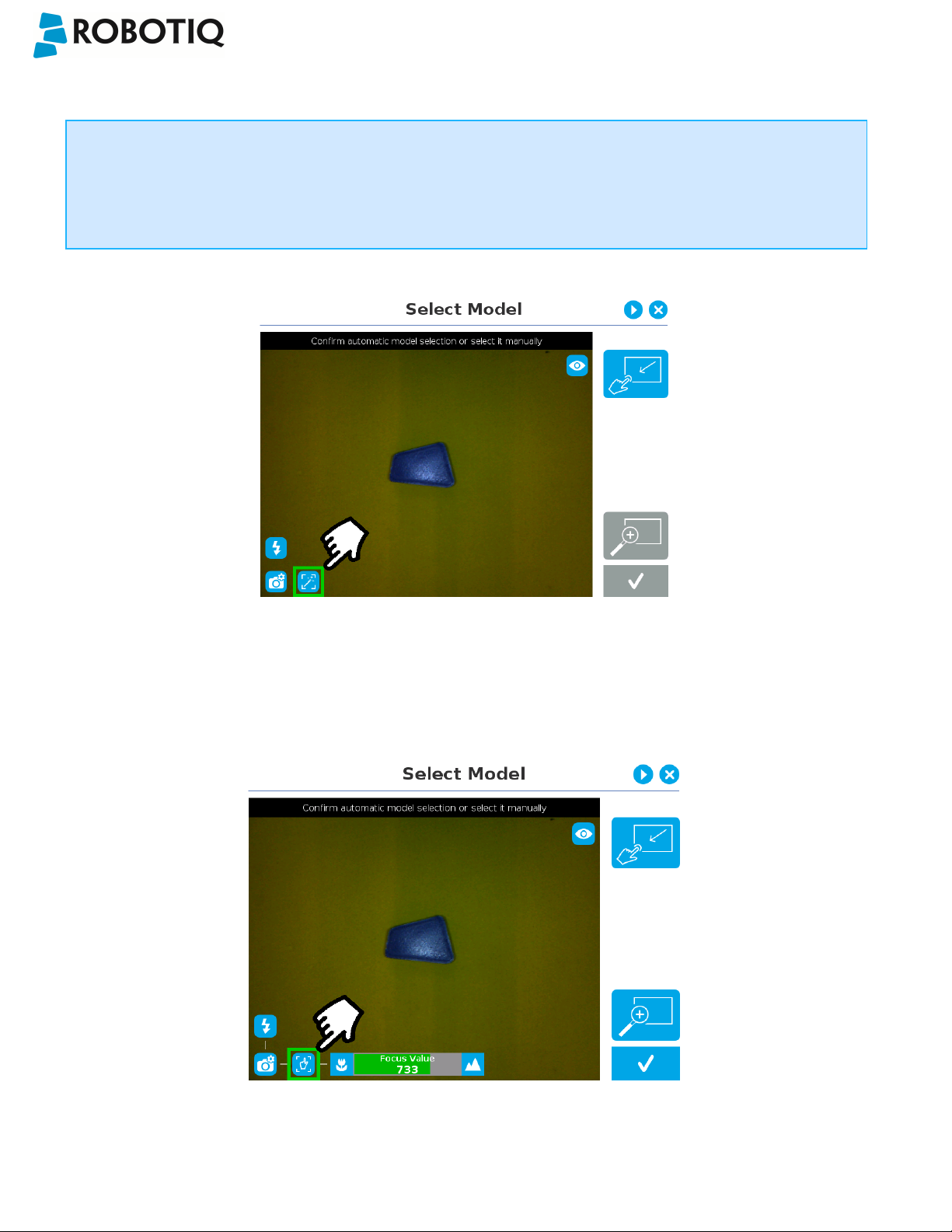
5.2.1.2. Select Model
Tip
At any moment during the teaching process, the user can access contextual help videos with the Play button.
Prior to selecting a model, the user will place a background on the workplane and then position the object on the
background. By default, the Select Model step displays the object to teach, automatically selected by the software,
meaning a green selection rectangle overlaps the shape of the object.
Magic Wand tool; please refer to the Automatic
area selection section for more details.
Tap and drag tool; please refer to the Manual
area selection section for more details.
Zoom in button; please refer to the Zoom in
section for more details.
Zoom out button; please refer to the Zoom out
section for more details.
Accept model button for finalizing the model
selection step; please refer to the Accepting the
model section for more details.
Camera settings button; please refer to the
Camera settings section for moredetails.
Standard view button; please refer to the
Standard view section for more details.
Machine edge view button; please refer to the
Machine edge view section for more details.
©Robotiq inc. 2016-2018
Machine color view;please refer to the Machine
color view section for more details.
45

Wrist Camera Instruction Manual
Automatic area selection
The object is selected since the Magic Wand tool is enabled by default. The Magic Wand feature allows to locate objects
on the background without user intervention.
Info
For the automatic area selection feature to function properly, the user has to employ a uniform background, and a
single object with well defined edges.
Tip
Tapping the Magic Wand tile in the right pane of the PolyScope interface switches the area selection mode to
Manual.
©Robotiq inc. 2016-2018
Fig. 5-4: Select Model step with object automatically selected by the Magic Wand tool
46

Wrist Camera Instruction Manual
Manual area selection
The user then selects an area by tapping the screen and dragging his/her finger to contain the desired object in the
selection area.
Fig. 5-5: Select Model step with Manual area selection feature
Tip
The manual area selection is useful for careful inspection of specific features using the zoom function.
Refer to the Zoom section for more details.
The manual area selection can also be used for partial custom object selection (i.e. for selecting standalone
features or components of an object).
Tip
Tapping the Manual selection button in the right pane will bring back the Automatic area selection mode.
©Robotiq inc. 2016-2018
47

Wrist Camera Instruction Manual
Camera views
Standard view
When in standard view mode, the camera feed displays a reasonably faithful image based on what is normally perceived
by the human eye (colored object on colored background).
Fig. 5-6: Select Model step with standard view enabled
Tip
Tapping the eye button in the upper right corner of the camera feed window will bring up the machine view.
©Robotiq inc. 2016-2018
48

Wrist Camera Instruction Manual
Machine edge view
The user can access the machine view by tapping the Color view button in the upper right corner of the camera feed
window. The machine view makes no discrimination between colors; it rather highlights the contour of the selected object.
Fig. 5-7: Select Model step with Machine edge view enabled
Tip
The Machine edge view is a convenient tool that can be used to better understand the quality of the image and
the object contrast, and to improve adjustments made to the selection.
Tip
Tapping the cube button in the upper right corner of the camera feed window will bring up the Machine color
view.
©Robotiq inc. 2016-2018
49

Wrist Camera Instruction Manual
Machine color view
The user can access the Machine color view by tapping the Machine edge view button in the upper right corner of the
camera feed window. The Machine color view displays the elementary colors perceived by the vision system.
Fig. 5-8: Select Model step with Machine color view enabled
Tip
The Machine color view is a convenient tool that can be used to better understand the color signature and scale
used by the system.
Tip
Tapping the drop button in the upper right corner of the camera feed window will bring up the standard view.
©Robotiq inc. 2016-2018
50
Wrist Camera Instruction Manual
Camera settings
In order to access the advanced camera settings, tap the camera/gear icon in the lower left corner of the camera feed.
Camera settings
Camera LEDs are ON; please refer to the Camera
LEDs section for more details.
Camera LEDs are OFF; please refer to the Camera
LEDs section for more details.
Automatic focus is enabled; please refer to the
Focus section for more details.
Manual focus is enabled; please refer to the Focus
section for more details.
Shallow focus button; please refer to the Focus
section for more details.
Deep focus button; please refer to the Focus
section for more details.
©Robotiq inc. 2016-2018
51

Camera LEDs
Wrist Camera Instruction Manual
Camera LEDs ON Camera LEDs OFF
Tip
The LEDs, when turned ON, sometimes highlight undesirable features or create reflections that distort the
teaching process. It is recommended to try both settings when teaching the object in order to select the most
conclusive result.
Warning
The flash and focus settings selected will be used at runtime unless changes are made at the Configure Model
step at the end of the teaching process.
Please refer to the Configure Model section for more details.
©Robotiq inc. 2016-2018
52
Wrist Camera Instruction Manual
Focus
Info
Focus features can be used to sharpen or diminish the contrast between the object and the background, and
adjust the depth of field. The settings will be captured at runtime except if changes are made to the model during
the Configure Model step. Please refer to the Configure Model section for more details.
Automatic focus
Fig. 5-9: Select Model step with automatic focus option enabled
To some extent, the automatic focus feature detects sharpness in the overall image. If the image is blurry, the autofocus
system will adjust the focus until sharpness and/or contrast is achieved. This type of automatic focus requires enough
contrast between the object and the background for it to render an appropriate image.
Manual fo cus
©Robotiq inc. 2016-2018
Fig. 5-10: Select Model step with manual focus option enabled
53
Wrist Camera Instruction Manual
The manual focus feature allows the user to adjust the depth of field. Tapping the flower button reduces the focus value,
making the depth of field narrower, while tapping the mountain button increases the focus value, making the depth of field
deeper.
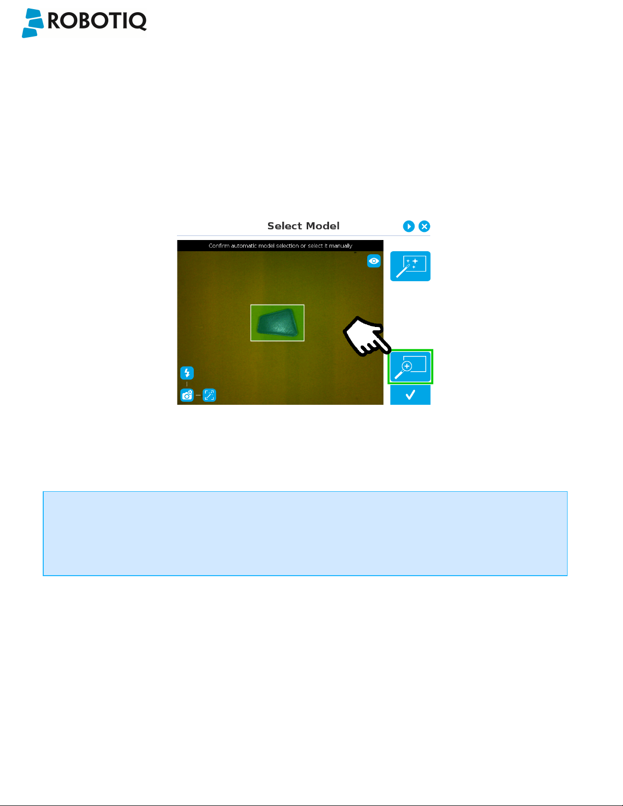
Zoom
The zoom-in/zoom-out tool is used to toggle between a high-level view and a more explicit view of the selection area
(andobject).
Zoom in
Fig. 5-11: Select Model step with Zoom in button highlighted
In order to zoom in on the selection area, the user has to tap the magnifier with a plus symbol in the lower right corner of
the teach pendant interface.
Once zoomed in, the user can perform focus adjustments to improve the recognition of edges in the model.
Info
Note that when zoomed in, the user can neither change the area selection mode nor accept the model selected
(the buttons are greyed out). The zoom in feature is therefore solely used for inspecting the model in details and
for adjusting the depth of field via the manual focus settings.
©Robotiq inc. 2016-2018
54

Zoom out
Wrist Camera Instruction Manual
Fig. 5-12: Select Model step with Zoom out button highlighted
In order to zoom out from the selection area, the user has to tap the magnifier with a minus symbol in the lower right corner
of the teach pendant interface.
Accepting the model
When the view of the model selected is satisfactory and you wish to carry on with the teaching wizard steps, tap the button
with the check mark in the lower right corner of the teach pendant interface.
©Robotiq inc. 2016-2018
Fig. 5-13: Select Model step with Accept button highlighted
55
Wrist Camera Instruction Manual
5.2.1.3. Edit Model
Tip
At any moment during the teaching process, the user can access contextual help videos with the Play button.
Right after accepting the model at the end of the Select Model step, the camera automatically zooms in on the object
selected. Quick selection modes and tools are made available to the user.
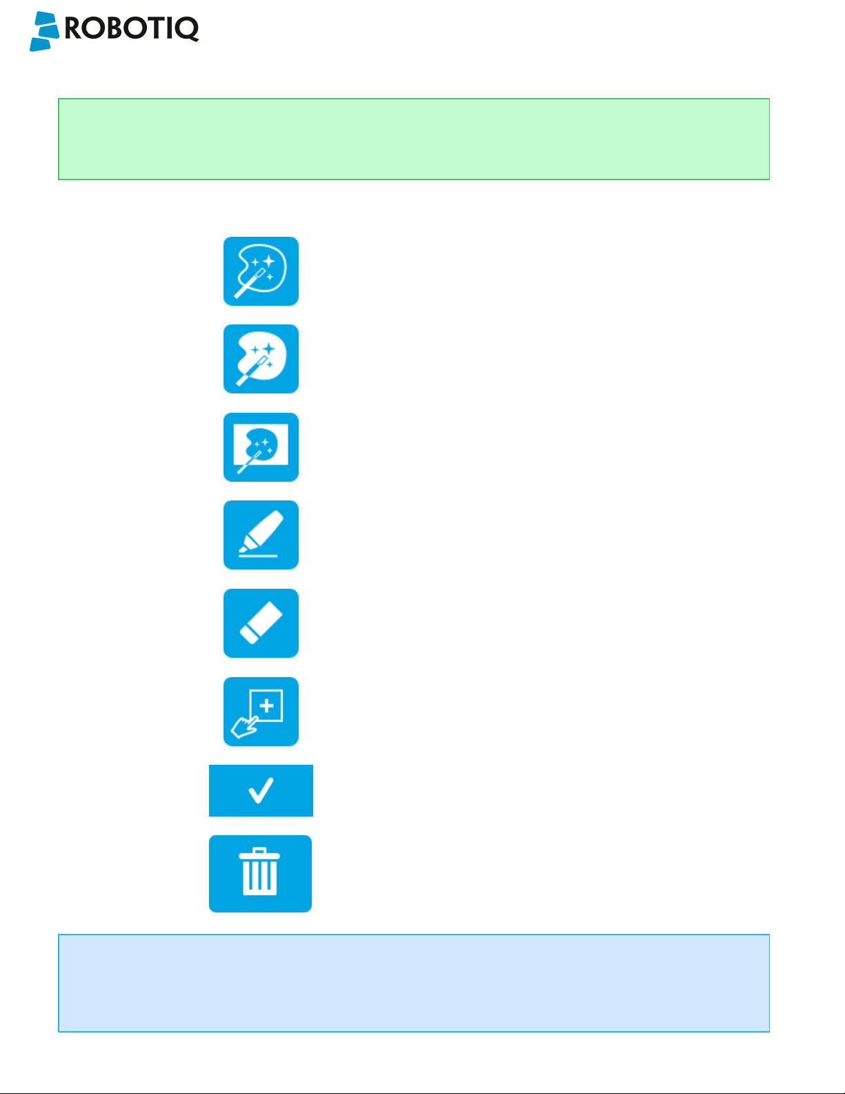
Outline only selection mode; please refer to the
Object Teaching section for more details.
Outline & surface selection model please refer to
the section for more details.
Rectangle selection around object please refer to
the section for more details.
Marker tool; please refer to the Object Teaching
section for more details.
Eraser tool; please refer to the Object Teaching
section for more details.
Rectangle+ (add area) tool; please refer to the
section for more details.
Accept model button; please refer to the
Accepting the model section for more details.
Info
The user can alternate between color and machine view while editing the model. Please refer to the Camera views
section for more details.
©Robotiq inc. 2016-2018
Delete selection area button; please refer to the
Accepting the model section for more details.
56
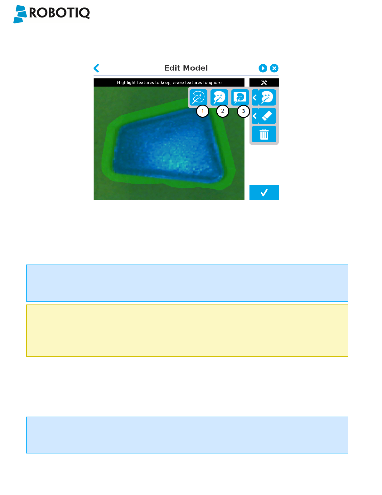
Quick selection modes
Tap the arrow to the left of the quick selection tool to expand the selection modes menu.
Wrist Camera Instruction Manual
Fig. 5-14: Edit Model step with quick selection modes expanded
1
Outline only
The Outline only selection tool is used to highlight the contour of the object
Info
The selection area bleeds off the edge of the object to capture the background color.
Caution
The Outline only selection tool is not available for an object that has been selected manually at the Select Model
step. This prevents users from selecting the partial contour of an object,which could lead to faulty contrasts and
edge detection.
2
Outline & surface
The Outline &surface selection tool is used to highlight the contour and upper surface of the object. Tap the middle
button. This tool is selected by default when the user accepts a model selected automatically during the Select
Model step.
Info
The selection area bleeds off the edge of the object to capture the background color.
©Robotiq inc. 2016-2018
57

Wrist Camera Instruction Manual
Caution
The Outline & surface selection tool is not available for an object that has been selected manually at the Select
Model step.This prevents users from selecting the partial outline and/or surface of an object, which could lead to
faulty contrasts and edge detection.
3
Rectangle around object
The Rectangle around object selection tool generates a rectangular selection area surrounding the object.
Info
The Rectangle around object selection tool is automatically selected when the object has been manually selected
at the Select Model step. The other options are disabled. This prevents users from selecting a partial outline
and/or surface of the object, which could lead to faulty contrasts, and erroneous color signature and background
identification.
©Robotiq inc. 2016-2018
58

Tools
Tap the arrow to the left of the tools button to expand the tools menu.
Wrist Camera Instruction Manual
1
Marker
The marker tool can be used to highlight features and edges to include and keep in the selection area.
Slide your finger or pointing device on the desired area(s) on the teach pendant. A green object layer mask will be
applied to the highlighted portion of the model.
2
Eraser
The eraser tool can be used to ignore features and edges in the selection area.
Slide your finger or pointing device on the undesired area(s) on the teach pendant. The object layer mask will be
replaced by the background layer mask.
3
Rectangle+ (add area)
The rectangle+ (add area) tool can be used to quickly highlight desired areas.
Tap and drag your finger or pointing device to draw rectangular shapes that will highlight presently available
features.
Deleting the selection area
4
Garbage can
Tapping the garbage can icon will clear the object layer mask, thus deleting the selection area.
Accepting the model
5
Check mark
When the view of the model is satisfactory and you wish to carry on with the teaching wizard steps, tap the button
with the check mark in the lower right corner of the teach pendant interface.
©Robotiq inc. 2016-2018
59

Wrist Camera Instruction Manual
Caution
Tapping the Accept model button (check mark) takes a picture of the model that will act as the first step in the next
phase of the teaching process:Refine Model.
©Robotiq inc. 2016-2018
60

Wrist Camera Instruction Manual
5.2.1.4. Refine Model
The Refine Model step prompts the user to take photos of the model in four different orientations. The purpose of this
step is to remove shade effects associated with the edges of the object in order to refine the model.
Info
The first photo is automatically generated at the end of the Edit Model step.
Info
Tap the camera icon to take a photo between each step. An error will pop up if the object has not been rotated.
1. The user is prompted to turn the object 90 degrees
clockwise. Note that the first picture is already taken,
in the upper right corner.
3. Object turned another 90 degrees clockwise. The
user is prompted to take the third picture.
Tip
2. The user is prompted to take the second picture of the
object.
4. Object turned another 90 degrees clockwise. The user is
prompted to take the fourth picture.
Tap on any snapshot taken in the object teaching wizard to enlarge it.
©Robotiq inc. 2016-2018
61

Wrist Camera Instruction Manual
5.2.1.5. Validate Model
Tip
At any moment during the teaching process, the user can access contextual help videos with the Play button.
The Validate Model step will start right after the fourth picture is taken at the end of the Refine Model step.
Info
If the object is properly detected, it will display green and red outlines.
If the object has not been recognized, please refer to the Guidelines on Object Teaching section for instructions.
Accept button
Retake button
The Validate Model step is used to verify the contour selection of the model. If satisfactory, the user can accept the model
by pressing the Accept button, or go through the Refine Model step again by tapping the Retake button.
Main points to observe:
l Object contours and detected features are outlined in green
l Features from the model that cannot be located on the object in the field of view of the camera are outlined in red.
©Robotiq inc. 2016-2018
62

Wrist Camera Instruction Manual
5.2.1.6. Scan Model
Tip
At any moment during the teaching process, the user can access contextual help videos with the Play button.
Warning
Scanning is an automatic process; the robot will move in order to perform calibration. Make sure the robot's work
space is clear. You can tap Cancel to stop the process. The operator should watch the robot at all time and have
the emergency stop button at hand.
Scan button used to start the scanning process
Cancel button used to abort the scanning process
while it is running
Fig. 5-15: Scan Model step with Scan button highlighted
The vision system will run a scan of the object by taking 9 pictures.
When the process is completed, the wizard will bring up the Configure Model step. Please refer to the Configure Model
section for more information.
©Robotiq inc. 2016-2018
63

Wrist Camera Instruction Manual
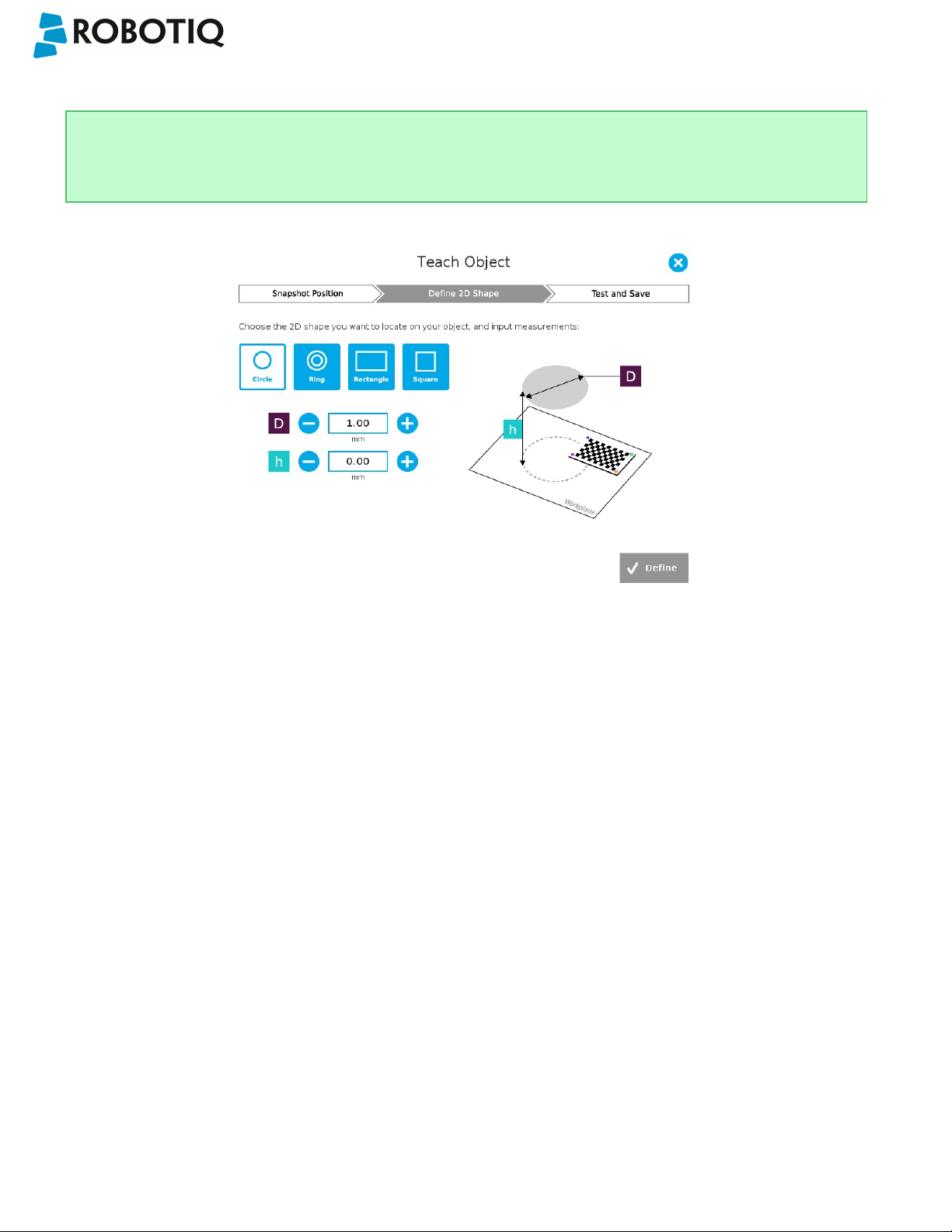
5.2.2. Parametric Method
When teaching a simple geometry object, it is recommended to use the Parametric method. It builds a model based on
parameters of a basic 2D shape (circle, ring, square or rectangle). This method allows the vision system to recognize and
locate with high robustness objects that have few distinctive features such as raw material blanks. It usually gives best
results than the Automatic method for simple geometry and highly reflective objects.
Choose the geometry that corresponds to the object to detect and define its parameters:
l Circle
l Ring
l Rectangle
l Square
Caution
In all cases, the height (h) is the distance between the workplane and the 2D shape. It considers and compensates
the thickness of the provided calibration board (roughly 3mm) that was used to calibrate the workplane.
Thus, if you calibrated the workplane using a printed version of the calibration board, you must add 3mm to the
height measurement.
Define button used to confirm the
dimensions of the object.
©Robotiq inc. 2016-2018
64
Wrist Camera Instruction Manual
5.2.2.1. Circle
Tip
At any moment during the teaching process, the user can access contextual help videos with the Play button.
Enter the circle diameter (D) and the height (h) at which the circle is located. Tap the Define button.
Fig. 5-16: Definition of a circle 2D shape.
©Robotiq inc. 2016-2018
65

Wrist Camera Instruction Manual
5.2.2.2. Ring
Enter the ring outer diameter (D), inner diameter (d) and the height (h) at which the ring is located. Tap the Define button.
Fig. 5-17: Definition of a ring 2D shape.
5.2.2.3. Rectangle
Enter the rectangle length (l),width (w) and the height (h) at which the rectangle is located. Tap the Define button.
Fig. 5-18: Definition of a rectangle 2D shape.
©Robotiq inc. 2016-2018
66

5.2.2.4. Square
Enter the square length (l) and the height (h) at which the square is located.
Wrist Camera Instruction Manual
Fig. 5-19: Definition of a square 2D shape.
When the process is done, the wizard will switch to the Configure Model step. Please refer to the Configure Model section
for more details.
©Robotiq inc. 2016-2018
67

5.2.3. Configure Model
Wrist Camera Instruction Manual
Test locating object button; the Vision System will search for the
object in the field of view of the Wrist Camera.
Back button; after testing an object's location, tap to return to the
output image of the camera.
Color validation button; tap to open the color validation menu.
A colored button Indicates that the color validation mode is enabled.
Please refer to the Color Validation section for more details.
Multiple Object Detection button; a grey button means the feature is
not available at the moment.
Tap to open the multi-object detection menu.
Detection Threshold button; tap to expand the detection threshold
menu. Please refer to the Detection thresholds and scores section for
more details.
©Robotiq inc. 2016-2018
Minus button; tap to lower the Detection Threshold. Please refer to
the Detection thresholds and scores section for more details.
Plus button; tap to increase the Detection Threshold. Please refer to
the Detection thresholds and scores section for more details.
68
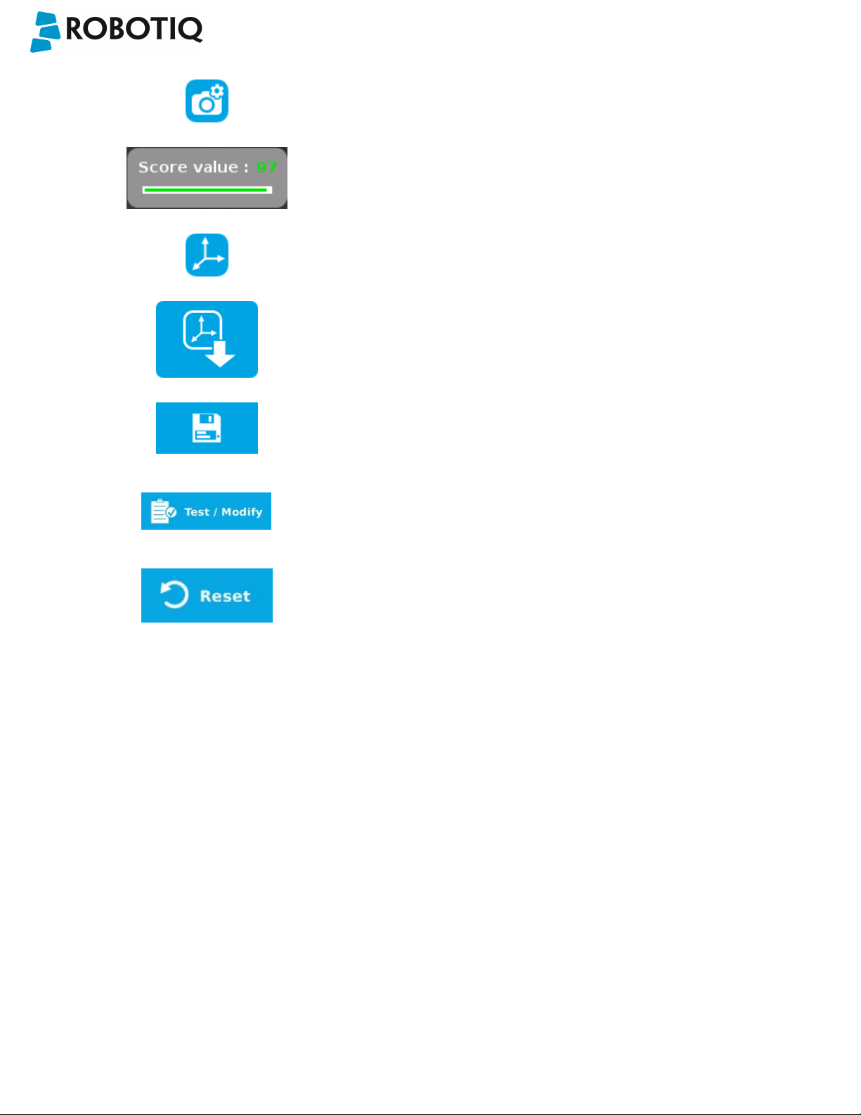
Wrist Camera Instruction Manual
Camera settings button; please refer to the Camera settings section
for more details.
Score value box; display section in which the detection score appears
after testing the object location.
Object location button; when an object is found, tap this button to
view its position relative to the robot base.
Set reference position button; tap to save the object's position for
programming linear move (MoveL) relative to the object's location.
Please refer to the Save location section for more details.
Save &finish button; tap to save the detection threshold, the
reference position and finish the wizard.
Test/Modify button; accessible via the Command tab of the Program
Robot interface in Polyscope, once the object teaching wizard is
completed. Tap to access the Test and Modify wizard. It allows the
user to modify the detection threshold and the saved object position.
Reset button; accessible via the Command tab of the Program Robot
interface in Polyscope, once the Teach object wizard is completed.
Tap to reset the whole process of the object teaching wizard.
©Robotiq inc. 2016-2018
69

Wrist Camera Instruction Manual
5.2.3.1. Multiple objects detection
In order to enable the multiple objects detection, tap the multi-object button from the Configure Model step.
Fig. 5-20: Configure Model with multi-object button highlighted.
Once in the multi-object menu, tap the plus (+) symbol to increase the maximum number of objects to detect, or tap the
minus (-) symbol to reduce that number.
©Robotiq inc. 2016-2018
Fig. 5-21: Configure Multiple Detection menu.
70

Wrist Camera Instruction Manual
5.2.3.2. Color Validation
Color validation adds reliability to the camera locate feature.
Whereas editing the model allows to select,configure and save the shape, outline and area of the model, the color
validation allows the system to save the color signature of objects or features.
Warning
Color validation is not intended for discriminating between two colors in the same Camera Locate node, no
matter what the purpose is. However, this action can be performed and programmed with two or more Camera
Locate nodes in the same program tree.
Color validation is not intended for eliminating all colors but one in a Camera Locate node, no matter what the
purpose is.
Automatic method
1
Tap the color validation button to access the color validation menu
©Robotiq inc. 2016-2018
Fig. 5-22: Configure Model with color validation button highlighted.
71

2
Turn on color validation by tapping the red button on the right side of the screen.
Wrist Camera Instruction Manual
Color sampling tools
Fig. 5-23: Configure Model Color model with ON/OFFbutton highlighted
1
Marker
The marker tool can be used to highlight features and edges to include and keep in the color sampling area.
Slide your finger or pointing device on the desired area(s) on the teach pendant. A green layer mask will be applied to
the highlighted portion of the model.
©Robotiq inc. 2016-2018
72

Wrist Camera Instruction Manual
2
Eraser
The eraser tool can be used to ignore features and edges in the color sampling area.
Slide your finger or pointing device on the undesired area(s) on the teach pendant.
3
Rectangle+ (add area)
The rectangle+ (add area) tool can be used to quickly highlight desired areas for color sampling.
Tap and drag your finger or pointing device to draw rectangular shapes that will highlight available features.
4
Garbage can
Tapping the garbage can icon will clear the object layer mask, thus deleting the selection area.
Info
The validation routine of the camera is performed in two steps:
1
Contour (edge) validation, with its own detection score
2
Color validation (if applicable), with its own detection score
Tip
Using the color validation helps to avoid false detections in your background.
©Robotiq inc. 2016-2018
73

Parametric method
1
Tap the color validation button to access the color validation menu.
Wrist Camera Instruction Manual
Fig. 5-24: Configure Model Step (Parametric method) with color validation button highlighted.
©Robotiq inc. 2016-2018
74

2
Turn on color validation by the tapping the red button on the right side of the screen.
Wrist Camera Instruction Manual
Fig. 5-25: Edit Color Validation menu (Parametric method) with ON/OFFtoggle button highlighted.
Color sampling tool
In the parametric method, given the inherent symmetry of the objects located by the system, color validation is supported
via an expendable/shrinkable color selection zone, on par with the contour of the object to be located.
Tap the plus icon to expand the color selection zone, and tap the minus button to shrink the selection zone.
Color selection zone (50% of object size) Color selection zone (80% of object size)
Caution
The size of the color selection zone ranges from 50% of the object size to 150% of the object size.
©Robotiq inc. 2016-2018
75

Wrist Camera Instruction Manual
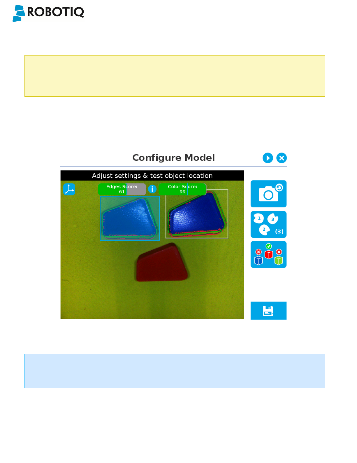
5.2.3.3. Detection thresholds and scores
At the Configure model step, the user can tap the Detection threshold button in the lower right corner to expand the
detection threshold settings.
Fig. 5-26: Configure Model Step with detection thresholds highlighted.
After adjusting the detection thresholds, if applicable, the user can test the location of the object(s)in the field of view by
tapping the camera icon.
©Robotiq inc. 2016-2018
Fig. 5-27: Configure Model Step with camera icon highlighted.
76

Wrist Camera Instruction Manual
Info
In the context of multiple objects detection, each object detected has its own set of detection score values (%).
©Robotiq inc. 2016-2018
77

Wrist Camera Instruction Manual
Edges detection threshold and score
If the object is found, you will see the object outlined, surrounded by a blue rectangle, with the detection score value (%).
Other objects detected will be surrounded by a white rectangle. Tap the other object(s) to display their own set of
detection score values.
Fig. 5-28: Object found with detection score.
l If no object is found, an error message will display, reading that the object was not found.
When testing the object(s) locating:
l Object contours and detected features are outlined in green
l Features from the model that cannot be located on the object in the field of view of the camera are outlined in red.
Info
In the context of multiple objects detection, each object detected has its own set of detection score values (%).
Info
When performing the localization test, place the whole object over the workplane. Due to the perspective effect,
some or all of the object features might not be recognized. If an important feature needs to be found for your
application (a hole for example), make sure it is found during all localization tests. Again, green contour should
match the object outlines at all times.
©Robotiq inc. 2016-2018
78

Wrist Camera Instruction Manual
Tip
To avoid false detections, remove the object from the workplane, decrease the detection threshold to 0% and try
to locate the object. If a false detection occurs on your workplane, you will see an object detected with the
detection score. Increase the detection threshold above this score to avoid false detection.
l Try all areas of the workplane on which the object might be found. Adjust the detection threshold properly for the
object and for the runtimeenvironment.
l Adjust the detection threshold with the plus (+) and minus (-) buttons.
Tip
Set the detection threshold at the highest value possible so the vision system detects the object on the whole
workplane. Tap the Test locating object button to test the threshold.
This ensures optimal robustness for object detection everywher on the workplane. If it is not possible to reach such a
success rate, the following should be considered:
l Redefine the Cam Locate node (go through the Teach object wizard again), make sure there are no reflections, or as
few as possible.
l Refer to the Guidelines on Object Teaching section for instructions
Tip
After completing the object teaching wizard, it is possible to edit the detection threshold. To do so, select the
Camera Locate node and go to the Command tab. Click on Test/Modify to edit the threshold and/or modify the
position of the object.
©Robotiq inc. 2016-2018
79
Wrist Camera Instruction Manual
Color detection threshold and score
Color detection can only happen following a successful edge detection.
Caution
Color validation must be enabled in order to go through the color detection step. Please refer to the Color
Validation section for more details on enabling color validation.
If the object goes through the 2-step detection successsfully, you will see the object(s) outlined,surrounded by a blue
rectangle, with the detection score values (%).
Other objects detected will be surrounded by a white rectangle. Tap the other object(s) to display their own set of
detection score values.
Fig. 5-29: Multiple objects found each with their selection rectangles and detection scores.
Info
In the context of multiple objects detection, each object detected has its own set of detection score values (%).
©Robotiq inc. 2016-2018
80

Wrist Camera Instruction Manual
5.2.3.4. Camera settings
Warning
Camera settings can be adjusted at the Select Model step of the Automatic teaching method and/or at the
Configure Model step of the Teach object wizard.
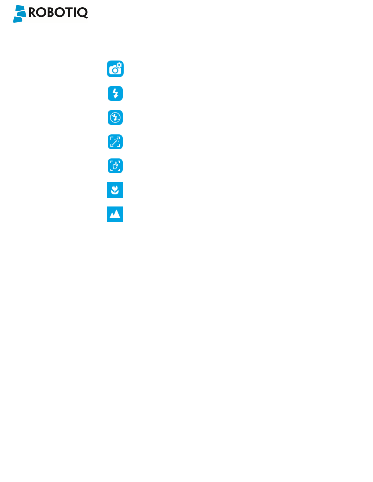
Editing the camera settings at the Configure Model step will override the settings selected at the Select Model
step of the Automatic teaching method.
Please refer to the Camera settings section for more details.
5.2.3.5. Save location
Once you are done with the test and adjustment, tap the Set reference position button.
Caution
Do not move the object after saving the position; the subsequent relative movements programmed will be relative
to that position. Please refer to the Programming with the Camera Locate Node section for more details.
Fig. 5-30: Position defined.
Once the position is saved, tap the Save & Reset button in the lower right corner of the teach pendant interface.
When you are done with the teaching process, the Camera Locate node will show you a snapshot of your saved object.
You can tap Reset to redefine completely. You can tap Test / Modify to change the detection threshold or both the
threshold and the saved object position.
©Robotiq inc. 2016-2018
81
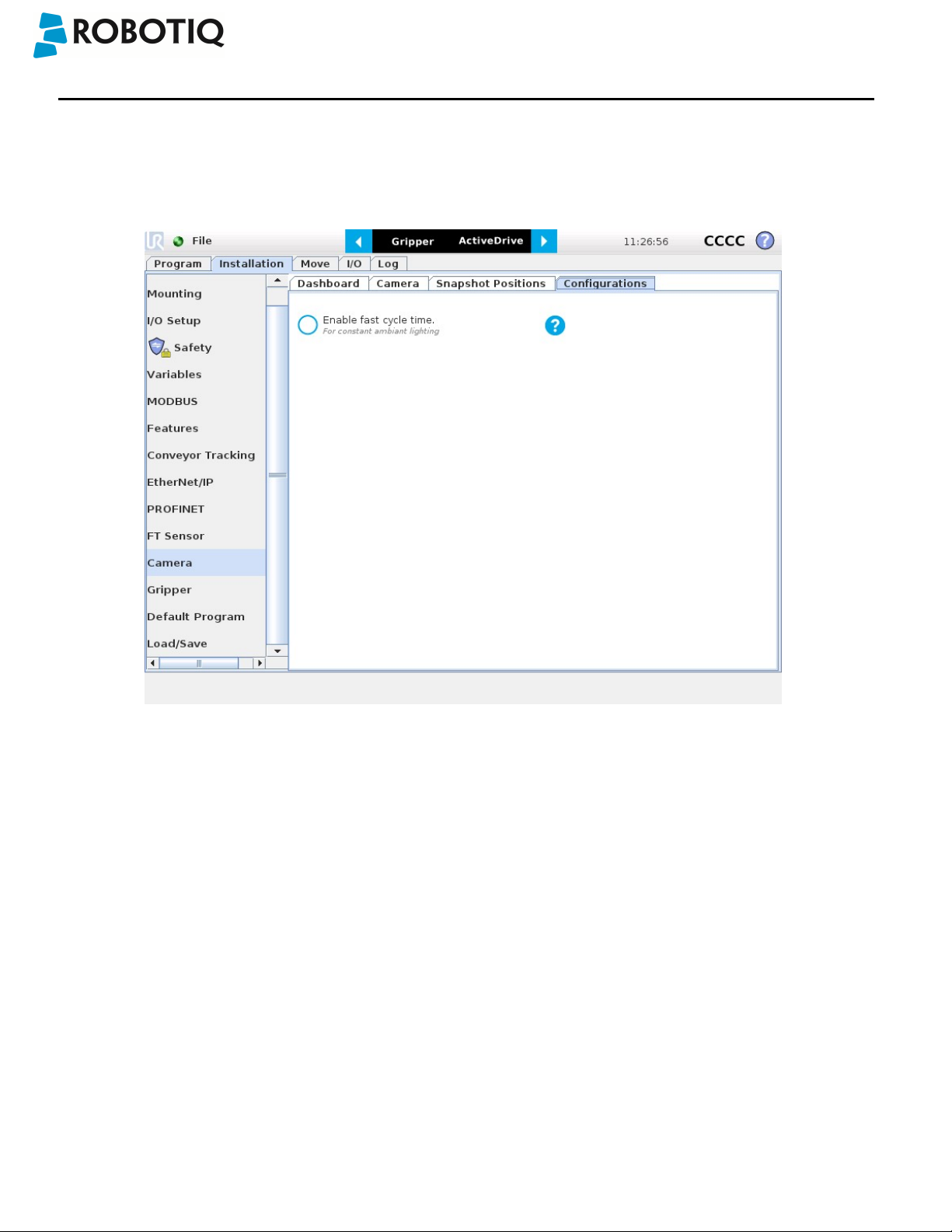
Wrist Camera Instruction Manual
6. Programming with the Camera Locate Node
Fast Cycle Time
If the ambient lighting is stable during run-time, you can enable the fast cycle time configuration. To do so, go to the
Installation tab from the program. Choose Camera and go to Configurations.
Fig. 6-1: Enable fast cycle time when ambient lighting is fixed.
©Robotiq inc. 2016-2018
82

Wrist Camera Instruction Manual
By enabling the fast cycle time configuration, the camera exposure will be set the first time the program enters a Camera
Locate node – at runtime. For all other Camera Locate nodes, the camera will keep the exposure settings from the first run.
This reduces the cycle time by half as opposed to not enabling the fast cycle time configuration.
Fig. 6-2: Fast cycle time configuration.
Fast Cycle Time
Enable the fast cycle time configuration only if the external ambient lighting is constant.
©Robotiq inc. 2016-2018
83

Wrist Camera Instruction Manual
Programming
The first thing to do after completing the object teaching is to add a Move node to the Snapshot position. When you exit
the object teaching wizard, the robot arm is already in the Snapshot position location. You can simply add a MoveJ
command before the Camera Locate node and set it to the location the robot arm is at (see Snapshot_pos_1 from the next
figure).
Caution
Make sure the robot arm is moved to the snapshot position before the Camera Locate node in the robot
program.
The Camera Locate node acts as an "if" statement. If the taught object is detected by the camera, the robot program will
enter in the Camera Locate node and execute all the command lines within it.
After teaching the object within the Camera Locate node, you may continue the programming by using either a linear move
(MoveL) with the snapshot position's variable as feature or the object_location pose. It is also possible to edit the
detection threshold or the saved object position after the Teach Object wizard.
l Refer to Section 6.1 to program a robot motion with a linear move (MoveL) with the snapshot position's variable as
feature. A template of this type of program is provided. This allows to perform robot motion relative to the object
detected at run time.
l Refer to Section 6.2 to use the object_location pose to program the robot motion - for advanced use.
l Refer to Section 6.3 to edit the detection threshold and/or the saved object position.
Cycle Time
The Camera Locate node cycle time is influenced by the background complexity, the object's features complexity
and the number of objects on the workplane.
To reduce the Camera Locate cycle time, consider the following:
l Have the least possible objects and object types on your workplane at run time.
l If your object has many detailed features, you can teach a drawing of it with simplified features or teach only
one area of the object.
l Have a diffuse ambient lighting, avoiding high light intensity spots on the workplane.
©Robotiq inc. 2016-2018
84

Wrist Camera Instruction Manual
6.1. Linear Move with Feature – Pick and Place Template
Info
The URCaps installation will provide you with a template program, template_vision.urp, that can be found in the
program folder.The figure below shows this template. This section guides you through the process of doing a
similar program.
Once the Teach Object wizard is completed, you saved the last position of your object. The object position variable,
named after the snapshot position, now contains the reference frame of the object in this saved position. Each time the
Camera Locate node localizes an object, it updates that feature variable's frame with the new detected object's position
and orientation. That feature is named according to the feature name you chose during the snapshot position definition.
Saved position
The saved object position from the Teach Object wizard or the Test/Save wizard is the position of the object to
be used for the relative robot motion programming. Once the position is saved, do not move the object to ensure
proper robot motion programming within the Camera Locate node.
You can use that reference feature inside the Camera Locate node within Move commands of the robot. To do so:
l Insert a Move node.
l In that node, go to the Command tab.
l Select MoveL.
l Select the appropriate feature (your Snapshot Position / Feature name).
Every waypoints inserted within that MoveL node will be relative to the feature updated by the Camera Locate. Without
moving your object, teach your waypoints according to it's position.
When you are done with the movements relative to the object, you can insert another Move node, selecting a movement
that is not relative, but absolute (base frame), and do normal movements.
This process will give you:
l A set of MoveL movements relative to the object orientation.
l A set of MoveJ, MoveL or MoveP movements relative to the absolute base frame.
In short, the template program will move to the Snapshot Position, search for the object, do a set of movement relative to
the object orientation, then do a set of movement relative to the robot base. It is provided and installed with the Camera
Locate URCap.
©Robotiq inc. 2016-2018
85

Wrist Camera Instruction Manual
Fig. 6-3: Template program for a Camera Locate pick & place application.
6.2. object_location pose
Once a snapshot position is defined, the workplane used for the calibration gets its own coordinate system, regardless of
its orientation. This coordinate system is shown in the figure below.
Fig. 6-4: workplane reference frame.
The camera will detect an object on the workplane and find its X-Y position, as well as its Z-orientation in the workplane's
coordinate system (see figure below). Thus, a detected object is always laid flat (parallel) to the workplane. It is possible to
use the object_location pose, which is a variable containing the detected object's pose (p[x, y, z, x rotation, y rotation, z
rotation]) in the robot's base reference frame.This variable is updated each time the program goes within a Camera Locate
node, thus every time an object is detected, regardless of how many Camera Locate nodes are in the program. The
object_location pose is relative to the robot's base frame.
Info
object_location is a variable containing the detected object's position and orientation relative to the base
reference frame. The orientation is always parallel to the workplane on which the calibration has been performed.
Thus, the object's X and Y axes are always parallel to the workplane. The Z axis is always normal to the workplane
and points downwards from it, into the workplane (refer to the figure below).
©Robotiq inc. 2016-2018
86
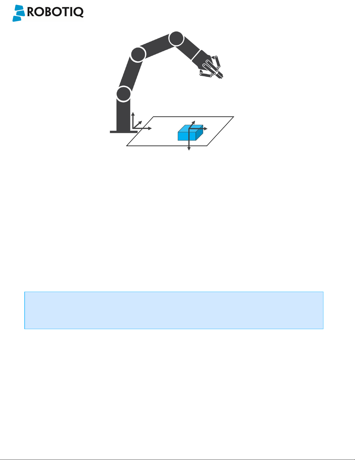
Fig. 6-5: object_location pose on the workplane used for the calibration.
Wrist Camera Instruction Manual
object_location is a variable with the pose structure (x, y, z, x rotation, y rotation, z rotation):
x: x position of the object detected, relative to the robot's base reference frame.
y: y position of the object detected, relative to the robot's base reference frame.
z: z position of the object detected, relative to the robot's base reference frame.
x rotation: x rotation from the robot's base frame to the detected object feature reference frame. The object's X axis is
parallel to the workplane on which the calibration has been performed.
y rotation: y rotation from the robot's base frame to the detected object feature reference frame. The object's Y axis is
parallel to the workplane on which the calibration has been performed.
z rotation: z rotation from the robot's base frame to the detected object feature reference frame. The object's Z axis is
normal to the workplane on which the calibration has been performed, points downwards from it, into the workplane.
If you move the robot's TCP to the object_location pose, the TCP will go and point the object on the workplane.
The height value of the object on the workplane should not be taken into account - the TCP might be directly on
the object when moving it to the object_location pose.
©Robotiq inc. 2016-2018
87
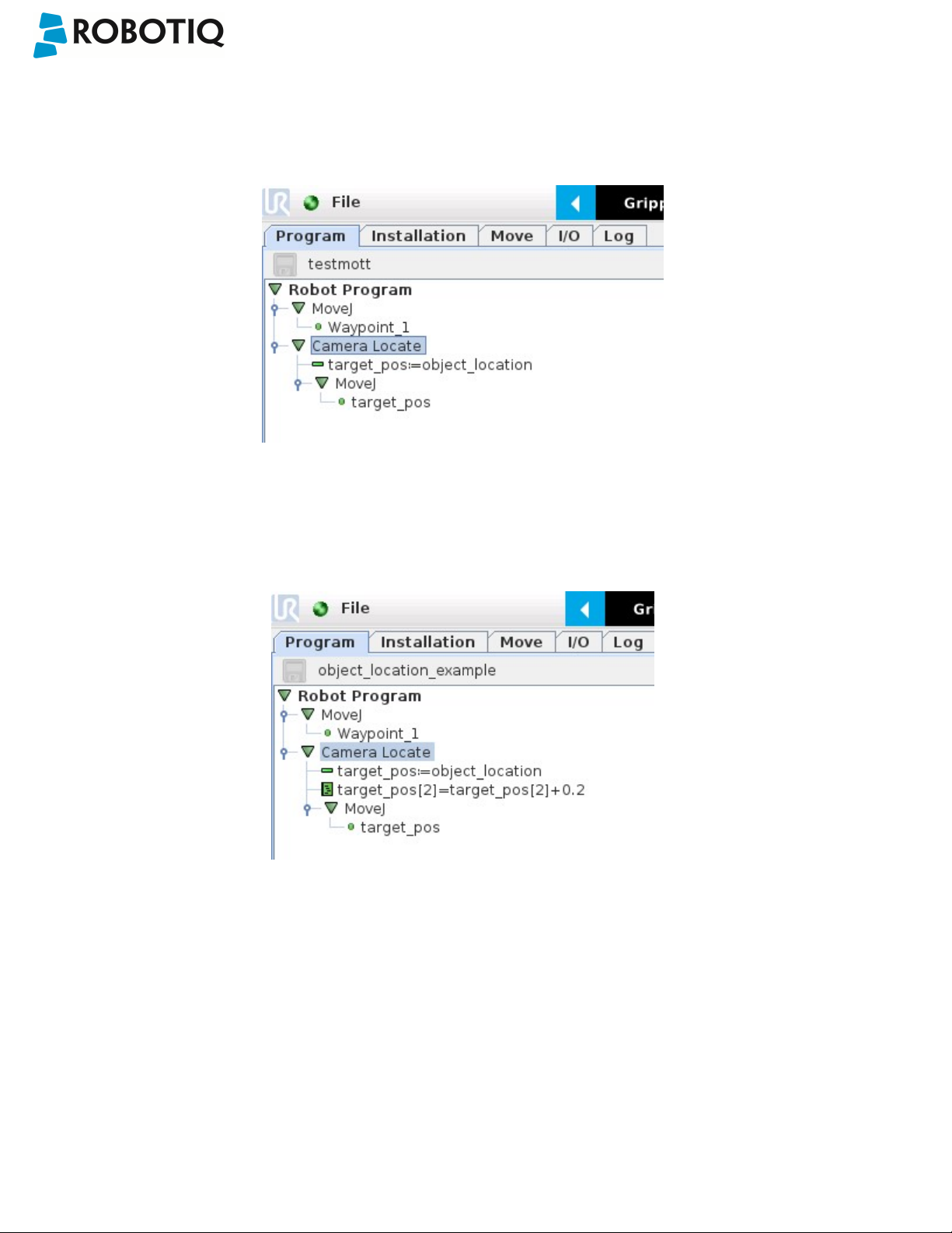
Wrist Camera Instruction Manual
Program Example
The program examples below show how to use the object_location pose variable.The first one simply moves the robot so
that the TCP goes directly on the detected object.Make sure the TCP is set properly to avoid collisions.
Fig. 6-6: Program example - place the TCP on the detected object.
The second example moves the robot so that the TCP goes 20 cm above the detected object. This is in the case of an
horizontal plane.
Fig. 6-7: Program example – Place the TCP 20 cm above the detected object, in case of an horizontal plane.
©Robotiq inc. 2016-2018
88

Wrist Camera Instruction Manual
6.3. Edit Detection Threshold and Object Location
It is possible to edit both the detection threshold and the object location after the Teach object wizard has been
completed. To do so, select the Cam Locate node, go to the Command tab and tap Test/Modify.
l To modify the saved object position, place the object in the desired position. Test is with the Test locating object
button and, when in the desired position, tap Define new position. The position is saved. Tap Save & close to exit the
wizard. This also saves the threshold.
l To modify only the detection threshold, modify it and test it. Once it is at the required value, tap Save & close. This
does not modify the object position previously saved.
l To modify both the threshold and the object location, adjust the threshold, place the object in the desired position
and test is with the Test locating object button. Once in the desired position, tap Define new position. The position is
saved. Tap Save & close to save the threshold.
©Robotiq inc. 2016-2018
89

Wrist Camera Instruction Manual
6.4. Camera Locate node at a variable Snapshot position
During a robot program, the robot must be at the snapshot position before entering the Camera Locate node. If it is not in
the right position, a pop-up will appear, preventing the camera from taking a snapshot from the wrong position. This is to
ensure good precision since the workplane has been previously calibrated for this snapshot position.
In some cases, it is helpful to move the robot to a variable position to enter a Camera Locate node. For instance, it can also
used to teach only one snapshot position and object to manage parts in stacked trays. In order to do so, allow the robot to
be in a different position that the original snapshot position by entering the script command:
ignore_snapshot_position = True
You also need to edit the snapshot_position_offset pose variable. This variable contains the pose offset between the
original saved snapshot position and the one used in the program .
The example shows a program using a Camera Locate node to manage parts in stacked trays.
l The script command in the BeforeStart section allows the camera not to be in the exact snapshot position when
entering a Camera Locate node.
l The pose at which the robot enters the Camera Locate node is calculated knowing how many trays are stacked.
l The snapshot_position_offset is calculated accordingly in order for the Wrist Camera to consider the pose offset from
the original snapshotposition.
ignore_snapshot_position = True
When using this method, make sure the workplane has the same orientation and distance regarding the position
of the camera before a Camera Locate node. Using a variable and relative snapshot position may decrease the
©Robotiq inc. 2016-2018
Fig. 6-8: Program example.
90

Wrist Camera Instruction Manual
precision, as the workplane can be slightly different depending on where the calibration has been performed. Be
aware of this when programming a Camera Locate node relative to another one.
©Robotiq inc. 2016-2018
91

Wrist Camera Instruction Manual
7. Specifications
Caution
The following manual uses the metric system, unless specified, all dimensions are in millimeters.
The following sub-sections provide data on the various specifications for the Robotiq 2-Finger 85 and 140 Adaptive
Grippers.
l Section 7.1 mechanical specifications of the Wrist Camera:
l Dimensions;
l Maximum load;
l Center of mass;
l Moment of inertia.
l Section 7.2 electrical rating & performance specifications of the Wrist Camera:
l Electrical supply;
l Resolution;
l FPS.
l Section 7.3 Vision System specifications:
l Field of view;
l Part size.
©Robotiq inc. 2016-2018
92

7.1. Mechanical Specifications of Wrist Camera
Wrist Camera Instruction Manual
Specification Value
Maximum load 10 kg 40 Nm
Weight (without tool plate) 160 g
Weight (with tool plate)
Added height (without tool plate, for use with 2Finger Gripper)
Global thickness (without tool plate) 22.4 mm
Added height (with tool plate) 23.5 mm
Global thickness (with tool plate) 29.5 mm
Wrist Camera's mechanical specifications.
Fig. 7-1: Wrist Camera's dimensions.
230 g
13.5 mm
Photographic sensor
Respecting Universal Robots's axes system, the photographic sensor's is located at [0mm; 35.7mm; -0.1mm] of
the tool flange on which the camera is mounted. The line of sight passes through this point and is at 30° from the
Z-axis.
©Robotiq inc. 2016-2018
93

Wrist Camera Instruction Manual
7.1.1. Center of Mass and Moment of Inertia
The coordinate system used to calculate the moment of inertia and center of mass of the Wrist Camera is the base of the
Camera which correspond to the UR tool flange reference [0,0,0].
Here is the approximate position for the center of mass. It has been calculated for the camera itself and for combinations
with other Robotiq products. The camera's tool plate is included when the gripper is not mounted on the Wrist Camera.
Combination x (mm) y (mm) z (mm) Mass (grams)
- 0
FT300
2-Finger 85
2-Finger 140
FT 300 and 2-Finger
0 2
0 1
0
0
5
9 230
30 530
58 975
1 66 1040
1 77 1275
85
FT 300 and 2-Finger
0
1 85 1340
140
Here is the approximate moment of inertia matrix for the Wrist Camera:
Inertia Matrix Metric value
(kg * mm2)
lxx lxy lxz 111 0 0 0.38 0 0
lyx lyy lyz 0 70 3 0 0.24 0.01
Imperial value
(lb * in2)
lzx lzy lzz 0 3 165 0 0.01 0.56
©Robotiq inc. 2016-2018
94

Fig. 7-2: Center of Mass with and without the toolplate.
Wrist Camera Instruction Manual
©Robotiq inc. 2016-2018
95

Wrist Camera Instruction Manual
7.2. Electrical rating & performance of Wrist Camera
Robotiq recommends you supply the Wrist Camera from the Universal Robots controller power supply as shown in the
Electrical Setup section; if for any reasons you cannot do so, here are the electrical specifications of the Camera:
Specification Value
Operating supply voltage 24 V DC
±20%
Quiescent power (minimum power
consumption)
Maximum power 22 W
Communication interface USB 2.0
Here are the Wrist Camera's specifications:
Specification Value
Maximum resolution 5 Mpx at 2 fps (2560 X
Maximum frame rate 30 fps at 0.3 Mpx (640 X
Active array size 2592 X 1944
Focus range 70 mm to infinity
1 W
1920)
480)
©Robotiq inc. 2016-2018
Integrated lighting 6 LED diffuse white light
Autofocus technology Liquid lense
96
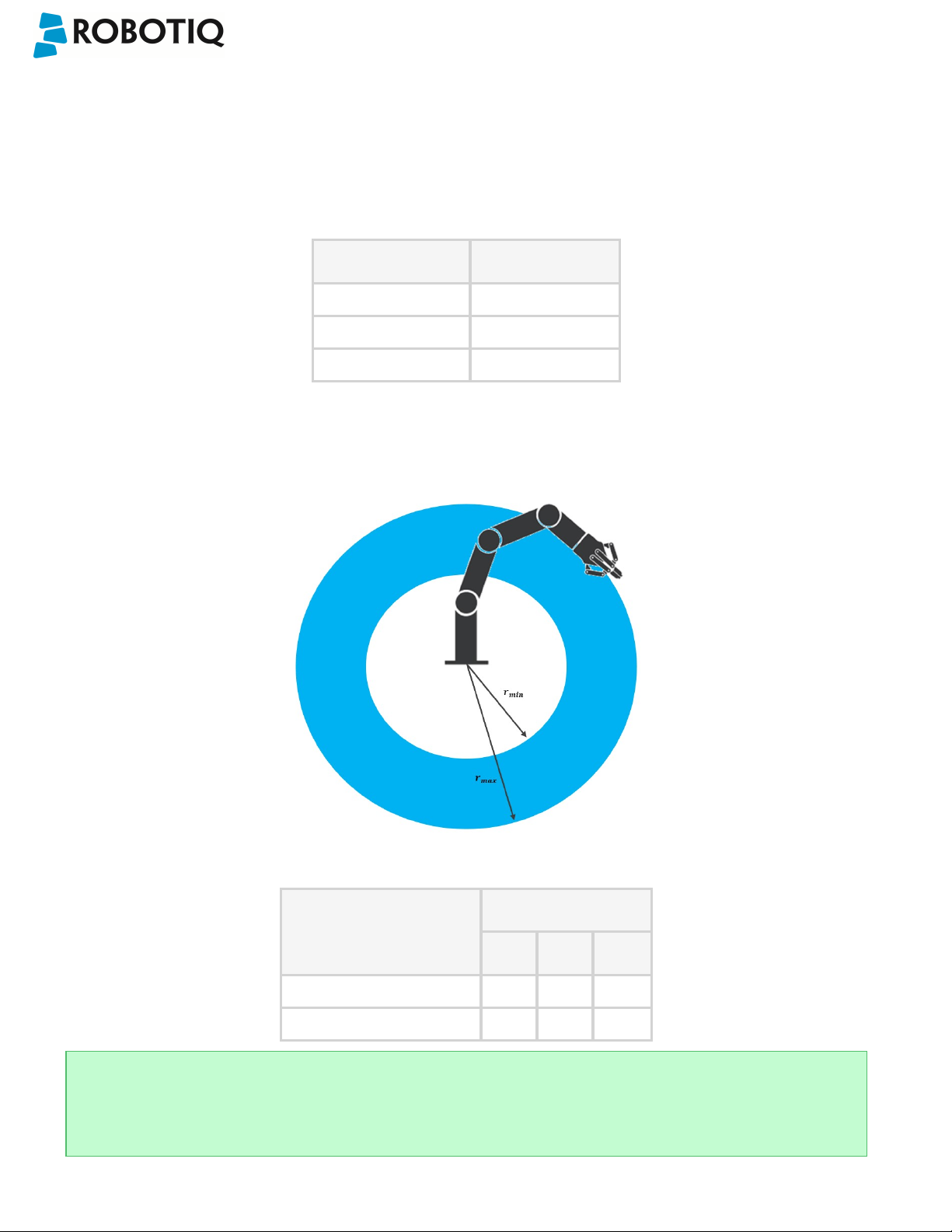
Wrist Camera Instruction Manual
7.3. Vision System Specifications
Accuracy
The accuracy of the vision system is as described in the table below and depends on the robot model used. It is valid for
the area where the calibration board was located during the calibration process.
Robot Model Accuracy
UR3 +/- 2mm
UR5 +/- 3mm
UR10 +/- 3mm
Fig. 7-3: Accuracy of the vision system.
Calibration board position
Tips
Snapshot Position will determine the field of view, notice that the calibration step position does not have to be the
same as Snapshot position. Thus, you can have a small field of view, then move back for calibration step.
©Robotiq inc. 2016-2018
Fig. 7-4: Calibration board position.
Specification Value
UR3 UR5 UR10
Minimum board distance (cm) 26 34 42
Maximum board dist ance (cm) 42 70 98
97

Wrist Camera Instruction Manual
Field of view
Specification Value
UR3 UR5 UR10
Maximum board dist ance (cm) 36 x 27 64 x 48 100 x 75
Minimum board distance (cm) 10 x 7.5 10 x 7.5 10 x 7.5
Info
Field of view is (FoV) determined by Snapshot position. To get the minimum FoV, the camera must be placed at 7
cm above the work plane.
©Robotiq inc. 2016-2018
98

Wrist Camera Instruction Manual
Part dimensions
The maximum part size that can be detected by the Wrist Camera is 60% field of view's dimension. The minimum is 10%,
no matter the robot or the field of view size.
Fig. 7-5: Maximum and minimum part size.
The part must not be higher than its smallest dimension (width or length) : maximum of 1:1 ratio.
Fig. 7-6: Maximum part height.
Info
Part height ratio is taken between the maximum part height at any point and the minimum dimension present on
part contour, width or length.
©Robotiq inc. 2016-2018
99

Wrist Camera Instruction Manual
Background contrast
To ensure a good model and part detection from the Vision system, you should use a background that has a high color
contrast with the part to be detected. You must choose colors that are apart horizontally on the HSV cone shown below.
Therefore, a change in value (intensity) only does not represent a good contrast. There has to be a great difference in hue
and saturation to obtain a good object model from the object teaching wizard. You can use either the yellow or pink side
of the colored background provided with the camera kit. If required, use a different colored background to teach yourpart.
©Robotiq inc. 2016-2018
Fig. 7-7: HSV color cone.
100
 Loading...