

© ROBOTIQ INC. 2012
Get the latest version of the manual at support.robotiq.com
1

Table of Contents
Revisions . . . . . . . . . . . . . . . . . . . . . . . . . . . . . . . . . . . . . . . . . . . . . . . . . . . . . . . . . . . . . . . . . . . . . . . . . . . . . . . . . . . . . . . . . . . . . . . . . . . . 3
1. General Presentation . . . . . . . . . . . . . . . . . . . . . . . . . . . . . . . . . . . . . . . . . . . . . . . . . . . . . . . . . . . . . . . . . . . . . . . . . . . . . . . . . . . . . . . . . 3
2. Safety . . . . . . . . . . . . . . . . . . . . . . . . . . . . . . . . . . . . . . . . . . . . . . . . . . . . . . . . . . . . . . . . . . . . . . . . . . . . . . . . . . . . . . . . . . . . . . . . . . . . . 8
2.1 Warning . . . . . . . . . . . . . . . . . . . . . . . . . . . . . . . . . . . . . . . . . . . . . . . . . . . . . . . . . . . . . . . . . . . . . . . . . . . . . . . . . . . . . . . . . . . . . . . 9
2.2 Intended use . . . . . . . . . . . . . . . . . . . . . . . . . . . . . . . . . . . . . . . . . . . . . . . . . . . . . . . . . . . . . . . . . . . . . . . . . . . . . . . . . . . . . . . . . . . 9
3. Installation . . . . . . . . . . . . . . . . . . . . . . . . . . . . . . . . . . . . . . . . . . . . . . . . . . . . . . . . . . . . . . . . . . . . . . . . . . . . . . . . . . . . . . . . . . . . . . . . . 9
3.1 Environmental and operating conditions . . . . . . . . . . . . . . . . . . . . . . . . . . . . . . . . . . . . . . . . . . . . . . . . . . . . . . . . . . . . . . . . . . . . . . 10
3.2 Mechanical connections . . . . . . . . . . . . . . . . . . . . . . . . . . . . . . . . . . . . . . . . . . . . . . . . . . . . . . . . . . . . . . . . . . . . . . . . . . . . . . . . . . 10
3.3 Power supply specifications . . . . . . . . . . . . . . . . . . . . . . . . . . . . . . . . . . . . . . . . . . . . . . . . . . . . . . . . . . . . . . . . . . . . . . . . . . . . . . . 11
3.4 Wiring . . . . . . . . . . . . . . . . . . . . . . . . . . . . . . . . . . . . . . . . . . . . . . . . . . . . . . . . . . . . . . . . . . . . . . . . . . . . . . . . . . . . . . . . . . . . . . . . 11
3.4.1 Power connection . . . . . . . . . . . . . . . . . . . . . . . . . . . . . . . . . . . . . . . . . . . . . . . . . . . . . . . . . . . . . . . . . . . . . . . . . . . . . . . . . . 12
3.4.2 Communication connection . . . . . . . . . . . . . . . . . . . . . . . . . . . . . . . . . . . . . . . . . . . . . . . . . . . . . . . . . . . . . . . . . . . . . . . . . . . 13
DeviceNet communication protocol . . . . . . . . . . . . . . . . . . . . . . . . . . . . . . . . . . . . . . . . . . . . . . . . . . . . . . . . . . . . . . . . . . . . . . 14
CANopen communication protocol . . . . . . . . . . . . . . . . . . . . . . . . . . . . . . . . . . . . . . . . . . . . . . . . . . . . . . . . . . . . . . . . . . . . . . 16
Real-time Ethernet communication protocol . . . . . . . . . . . . . . . . . . . . . . . . . . . . . . . . . . . . . . . . . . . . . . . . . . . . . . . . . . . . . . . 17
Serial communication protocol . . . . . . . . . . . . . . . . . . . . . . . . . . . . . . . . . . . . . . . . . . . . . . . . . . . . . . . . . . . . . . . . . . . . . . . . . . 19
4. Control . . . . . . . . . . . . . . . . . . . . . . . . . . . . . . . . . . . . . . . . . . . . . . . . . . . . . . . . . . . . . . . . . . . . . . . . . . . . . . . . . . . . . . . . . . . . . . . . . . . . 19
4.1 Generalities . . . . . . . . . . . . . . . . . . . . . . . . . . . . . . . . . . . . . . . . . . . . . . . . . . . . . . . . . . . . . . . . . . . . . . . . . . . . . . . . . . . . . . . . . . . . 20
4.2 Status overview . . . . . . . . . . . . . . . . . . . . . . . . . . . . . . . . . . . . . . . . . . . . . . . . . . . . . . . . . . . . . . . . . . . . . . . . . . . . . . . . . . . . . . . . . 20
4.3 Control overview . . . . . . . . . . . . . . . . . . . . . . . . . . . . . . . . . . . . . . . . . . . . . . . . . . . . . . . . . . . . . . . . . . . . . . . . . . . . . . . . . . . . . . . . 21
4.4 Status LEDs . . . . . . . . . . . . . . . . . . . . . . . . . . . . . . . . . . . . . . . . . . . . . . . . . . . . . . . . . . . . . . . . . . . . . . . . . . . . . . . . . . . . . . . . . . . 21
4.4.1 Supply LED . . . . . . . . . . . . . . . . . . . . . . . . . . . . . . . . . . . . . . . . . . . . . . . . . . . . . . . . . . . . . . . . . . . . . . . . . . . . . . . . . . . . . . . 22
4.4.2 Communication LED . . . . . . . . . . . . . . . . . . . . . . . . . . . . . . . . . . . . . . . . . . . . . . . . . . . . . . . . . . . . . . . . . . . . . . . . . . . . . . . . 22
4.4.3 Fault LED . . . . . . . . . . . . . . . . . . . . . . . . . . . . . . . . . . . . . . . . . . . . . . . . . . . . . . . . . . . . . . . . . . . . . . . . . . . . . . . . . . . . . . . . . 22
4.5 Gripper register mapping . . . . . . . . . . . . . . . . . . . . . . . . . . . . . . . . . . . . . . . . . . . . . . . . . . . . . . . . . . . . . . . . . . . . . . . . . . . . . . . . . 23
4.6 Robot output registers & functionalities . . . . . . . . . . . . . . . . . . . . . . . . . . . . . . . . . . . . . . . . . . . . . . . . . . . . . . . . . . . . . . . . . . . . . . . 24
4.7 Robot input registers & status . . . . . . . . . . . . . . . . . . . . . . . . . . . . . . . . . . . . . . . . . . . . . . . . . . . . . . . . . . . . . . . . . . . . . . . . . . . . . . 29
4.8 Example . . . . . . . . . . . . . . . . . . . . . . . . . . . . . . . . . . . . . . . . . . . . . . . . . . . . . . . . . . . . . . . . . . . . . . . . . . . . . . . . . . . . . . . . . . . . . . 33
4.9 MODBUS RTU communication protocol . . . . . . . . . . . . . . . . . . . . . . . . . . . . . . . . . . . . . . . . . . . . . . . . . . . . . . . . . . . . . . . . . . . . . . 33
4.9.1 Connection setup . . . . . . . . . . . . . . . . . . . . . . . . . . . . . . . . . . . . . . . . . . . . . . . . . . . . . . . . . . . . . . . . . . . . . . . . . . . . . . . . . . . 34
4.9.2 Read holding registers (FC03) . . . . . . . . . . . . . . . . . . . . . . . . . . . . . . . . . . . . . . . . . . . . . . . . . . . . . . . . . . . . . . . . . . . . . . . . 34
4.9.3 Preset single register (FC06) . . . . . . . . . . . . . . . . . . . . . . . . . . . . . . . . . . . . . . . . . . . . . . . . . . . . . . . . . . . . . . . . . . . . . . . . . . 35
4.9.4 Preset multiple registers (FC16) . . . . . . . . . . . . . . . . . . . . . . . . . . . . . . . . . . . . . . . . . . . . . . . . . . . . . . . . . . . . . . . . . . . . . . . 35
4.10 MODBUS TCP communication protocol . . . . . . . . . . . . . . . . . . . . . . . . . . . . . . . . . . . . . . . . . . . . . . . . . . . . . . . . . . . . . . . . . . . . . 36
4.10.1 Connection Setup . . . . . . . . . . . . . . . . . . . . . . . . . . . . . . . . . . . . . . . . . . . . . . . . . . . . . . . . . . . . . . . . . . . . . . . . . . . . . . . . . 36
4.10.2 Read Input Registers (FC04) . . . . . . . . . . . . . . . . . . . . . . . . . . . . . . . . . . . . . . . . . . . . . . . . . . . . . . . . . . . . . . . . . . . . . . . . . 36
4.10.3 Preset Multiple Registers (FC16) . . . . . . . . . . . . . . . . . . . . . . . . . . . . . . . . . . . . . . . . . . . . . . . . . . . . . . . . . . . . . . . . . . . . . 37
5. User Interface . . . . . . . . . . . . . . . . . . . . . . . . . . . . . . . . . . . . . . . . . . . . . . . . . . . . . . . . . . . . . . . . . . . . . . . . . . . . . . . . . . . . . . . . . . . . . . 38
5.1 Requirements . . . . . . . . . . . . . . . . . . . . . . . . . . . . . . . . . . . . . . . . . . . . . . . . . . . . . . . . . . . . . . . . . . . . . . . . . . . . . . . . . . . . . . . . . . 39
5.2 Installation . . . . . . . . . . . . . . . . . . . . . . . . . . . . . . . . . . . . . . . . . . . . . . . . . . . . . . . . . . . . . . . . . . . . . . . . . . . . . . . . . . . . . . . . . . . . . 39
5.3 UI Description . . . . . . . . . . . . . . . . . . . . . . . . . . . . . . . . . . . . . . . . . . . . . . . . . . . . . . . . . . . . . . . . . . . . . . . . . . . . . . . . . . . . . . . . . . 41
5.4 Connection . . . . . . . . . . . . . . . . . . . . . . . . . . . . . . . . . . . . . . . . . . . . . . . . . . . . . . . . . . . . . . . . . . . . . . . . . . . . . . . . . . . . . . . . . . . . 43
5.4.1 Modbus RTU . . . . . . . . . . . . . . . . . . . . . . . . . . . . . . . . . . . . . . . . . . . . . . . . . . . . . . . . . . . . . . . . . . . . . . . . . . . . . . . . . . . . . . 43
5.4.2 Modbus TCP . . . . . . . . . . . . . . . . . . . . . . . . . . . . . . . . . . . . . . . . . . . . . . . . . . . . . . . . . . . . . . . . . . . . . . . . . . . . . . . . . . . . . . 43
5.5 Control of the Adaptive Gripper . . . . . . . . . . . . . . . . . . . . . . . . . . . . . . . . . . . . . . . . . . . . . . . . . . . . . . . . . . . . . . . . . . . . . . . . . . . . . 44
5.5.1 Initialization & Gripper Status . . . . . . . . . . . . . . . . . . . . . . . . . . . . . . . . . . . . . . . . . . . . . . . . . . . . . . . . . . . . . . . . . . . . . . . . . 44
5.5.2 Interface Options . . . . . . . . . . . . . . . . . . . . . . . . . . . . . . . . . . . . . . . . . . . . . . . . . . . . . . . . . . . . . . . . . . . . . . . . . . . . . . . . . . . 44
5.5.3 Operation Mode . . . . . . . . . . . . . . . . . . . . . . . . . . . . . . . . . . . . . . . . . . . . . . . . . . . . . . . . . . . . . . . . . . . . . . . . . . . . . . . . . . . . 45
5.5.4 Control Parameters . . . . . . . . . . . . . . . . . . . . . . . . . . . . . . . . . . . . . . . . . . . . . . . . . . . . . . . . . . . . . . . . . . . . . . . . . . . . . . . . . 45
5.5.5 Gripper Feedback . . . . . . . . . . . . . . . . . . . . . . . . . . . . . . . . . . . . . . . . . . . . . . . . . . . . . . . . . . . . . . . . . . . . . . . . . . . . . . . . . . 46
5.6 Configuration of the Adaptive Gripper . . . . . . . . . . . . . . . . . . . . . . . . . . . . . . . . . . . . . . . . . . . . . . . . . . . . . . . . . . . . . . . . . . . . . . . . 47
5.6.1 Ethernet IP . . . . . . . . . . . . . . . . . . . . . . . . . . . . . . . . . . . . . . . . . . . . . . . . . . . . . . . . . . . . . . . . . . . . . . . . . . . . . . . . . . . . . . . . 47
5.6.2 Modbus TCP . . . . . . . . . . . . . . . . . . . . . . . . . . . . . . . . . . . . . . . . . . . . . . . . . . . . . . . . . . . . . . . . . . . . . . . . . . . . . . . . . . . . . . 49
5.6.3 DeviceNet . . . . . . . . . . . . . . . . . . . . . . . . . . . . . . . . . . . . . . . . . . . . . . . . . . . . . . . . . . . . . . . . . . . . . . . . . . . . . . . . . . . . . . . . 51
5.7 Menu Options . . . . . . . . . . . . . . . . . . . . . . . . . . . . . . . . . . . . . . . . . . . . . . . . . . . . . . . . . . . . . . . . . . . . . . . . . . . . . . . . . . . . . . . . . . 53
6. Specifications . . . . . . . . . . . . . . . . . . . . . . . . . . . . . . . . . . . . . . . . . . . . . . . . . . . . . . . . . . . . . . . . . . . . . . . . . . . . . . . . . . . . . . . . . . . . . . . 53
6.1 Technical dimensions . . . . . . . . . . . . . . . . . . . . . . . . . . . . . . . . . . . . . . . . . . . . . . . . . . . . . . . . . . . . . . . . . . . . . . . . . . . . . . . . . . . . 54
6.2 Mechanical specifications . . . . . . . . . . . . . . . . . . . . . . . . . . . . . . . . . . . . . . . . . . . . . . . . . . . . . . . . . . . . . . . . . . . . . . . . . . . . . . . . . 55
6.3 Moment of inertia and center of mass . . . . . . . . . . . . . . . . . . . . . . . . . . . . . . . . . . . . . . . . . . . . . . . . . . . . . . . . . . . . . . . . . . . . . . . . 56
6.4 Electrical ratings . . . . . . . . . . . . . . . . . . . . . . . . . . . . . . . . . . . . . . . . . . . . . . . . . . . . . . . . . . . . . . . . . . . . . . . . . . . . . . . . . . . . . . . . 56
6.5 Faceplates . . . . . . . . . . . . . . . . . . . . . . . . . . . . . . . . . . . . . . . . . . . . . . . . . . . . . . . . . . . . . . . . . . . . . . . . . . . . . . . . . . . . . . . . . . . . . 56
6.5.1 Blank faceplate . . . . . . . . . . . . . . . . . . . . . . . . . . . . . . . . . . . . . . . . . . . . . . . . . . . . . . . . . . . . . . . . . . . . . . . . . . . . . . . . . . . . 56
6.5.2 Yaskawa SDA-5D_10D faceplate . . . . . . . . . . . . . . . . . . . . . . . . . . . . . . . . . . . . . . . . . . . . . . . . . . . . . . . . . . . . . . . . . . . . . . 57
7. Warranty . . . . . . . . . . . . . . . . . . . . . . . . . . . . . . . . . . . . . . . . . . . . . . . . . . . . . . . . . . . . . . . . . . . . . . . . . . . . . . . . . . . . . . . . . . . . . . . . . . 58
8. Contact . . . . . . . . . . . . . . . . . . . . . . . . . . . . . . . . . . . . . . . . . . . . . . . . . . . . . . . . . . . . . . . . . . . . . . . . . . . . . . . . . . . . . . . . . . . . . . . . . . . . 59
Robotiq inc. © 2011 2

Robotiq Adaptative Gripper, S model Instruction Manual
Revisions
Robotiq may modify this product without notice, when necessary, due to product improvements, modifications or changes in specifications. If such
modification is made, the manual will also be revised, see revision information. See the latest version of this manual online at
. http://support.robotiq.com/
Revision 120209
Update for Robotiq Adaptive Gripper S model 5.1
Revision 120118
Update for Robotiq Firmware 3.0
Revision 111031
Sections added: User Interface and MODBUS TCP communication protocol
Revision 110515
Manual release
Copyright
© 2011 Robotiq Inc. All rights reserved.
This manual, and the product it describes, are protected by the Copyright Act of Canada, by laws of other countries, and by international treaties,
and therefore may not be reproduced in whole or in part, whether for sale or not, without prior written consent from Robotiq. Under copyright law,
copying includes translation into another language or format.
Information provided by Robotiq in this document is believed to be accurate and reliable. However, no responsibility is assumed by Robotiq for its
use. There may be some differences between the manual and the product if the product has been modified after the edition date.
The information contained in this document is subject to change without notice.
Robotiq inc. © 2011 3
Robotiq Adaptative Gripper, S model Instruction Manual
1. General Presentation
The terms "Gripper", "Adaptive Gripper", "Robotiq Gripper" and "Robotiq Adaptive Gripper" used in the following manual all refer to the Robotiq
Adaptive Gripper . The Robotiq Adaptive Gripper S model is a robotic peripheral that is designed for industrial applications. Its designS model
makes it a unique robotic end-of-arm tool to pick, place and handle a large range and volume of parts of varying sizes and shapes.
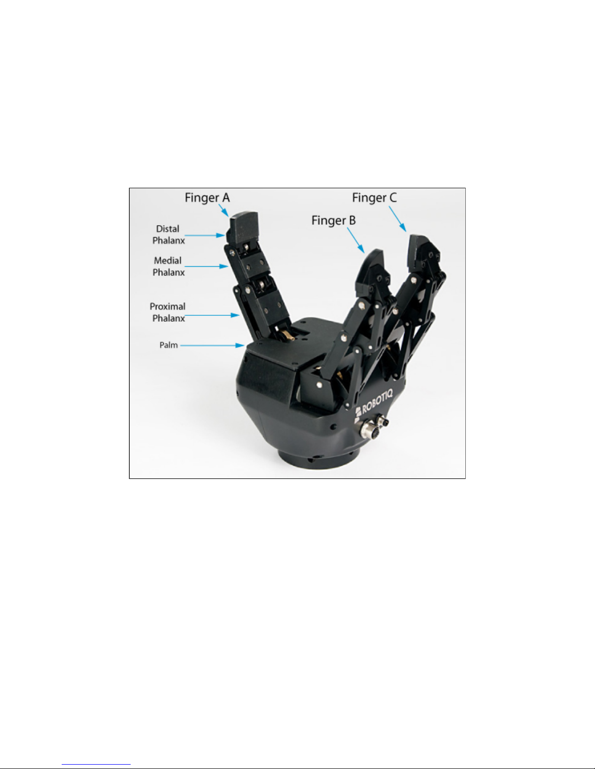
The Adaptive Gripper has three articulated fingers, i.e. finger A in front of finger B and finger C, that each have three joints (three phalanxes per
finger), as shown in Figure 1.1. The Gripper can engage up to ten points of contact with objects (three on each of the phalanges plus the palm).
The fingers are under-actuated, meaning they have fewer motors than the total number of joints. This configuration allows the fingers to
automatically adapt to the shape of object they grip and it also simplifies the control of the Gripper.
Figure 1.1 – The Adaptive Gripper S model.
Two different types of movements can be performed with the Gripper. The first one simultaneously changes the orientation of fingers B and C as
shown in Figure 1.2. That movement is referred to as changing Operation Modes. The Operation Mode is determined by the user prior to the grip
in function of the size or the shape of the object and for the task that has to be done.
Robotiq inc. © 2011 4

Robotiq Adaptative Gripper, S model Instruction Manual
1.
2.
3.
4.
Figure 1.2 – First type of movement of the Adaptive Gripper S model: changing the Operation Mode
The is the most versatile Operation Mode. It is best suited for objects that have one dimension longer than the two othersbasic mode
but can grip a large variety of objects.
The is optimal for gripping round or large objects.wide mode
The is used for small objects that have to be picked precisely. This Operation Mode can only grip objects between the distalpinch mode
phalanxes of the fingers.
The is used primarily for tiny objects. This mode is not very powerful but is precise. In scissor mode, it is not possible toscissor mode
surround an object. Here, fingers B and C move laterally towards each other while finger A remains still.
The four pre-set Operation Modes can be chosen by the user (see Figure 1.3).
Figure 1.3 – The four Operation Modes of the Adaptive Gripper.
Robotiq inc. © 2011 5

Robotiq Adaptative Gripper, S model Instruction Manual
The second movement of the Gripper is the closing and opening of the fingers as shown in Figure 1.4. This action is performed with a single input
from a user. Each finger is not controlled independently; the Gripper itself closes each finger until it reaches a stable configuration, on an object or
against the Gripper palm. Note that a user can specify the relative speed at which the fingers will close and the relative force that will be applied to
an object.
Figure 1.4 – Second movement of the Adaptive Gripper S model: closing and opening the fingers.
Two types of grips occur when closing the Adaptive Gripper S model on an object: Fingertip Grip or Encompassing Grip.
The is when an object is only held by the distal phalanxes. This type of grip is similar to what is done with conventionalFingertip Grip
industrial parallel grippers. In this situation, the stability of the grip is mainly related to the friction between the fingers and the object.
The is when the fingers surround an object. The object is encompassed within the fingers and the stability of theEncompassing Grip
grip is no longer related to friction. We suggest using the Encompassing Grip whenever possible to increase grip stability. Figure 1.5
shows the two types of grips.
Robotiq inc. © 2011 6

Robotiq Adaptative Gripper, S model Instruction Manual
Figure 1.5 – The Two Types of Grip: Encompassing and Fingertip Grips.
It is important to note that a Fingertip Grip can only be performed when the fingers touch the object with the distal phalanxes first. Inversely, for an
Encompassing Grip, the fingers must touch the object with the proximal or medial phalanxes first. Also, to ensure stability, the object should be
held against the Gripper palm before doing an Encompassing Grip.
Note that the Encompassing Grip cannot occur in all Operation Modes. Thereby, in Pinch and Scissor modes, it is only possible to do Fingertip
Gripping. On the other side, the Fingertip Grip can occur in all four Operation Modes. Figure 1.6 summarizes the Types of Grip possible for each
Operation Mode.
Info
Operation Modes are inputs to the Gripper. Whether the fingers close to produce an Encompassing or Fingertip grip is
. It will depend on:decided at the Gripper level automatically
The Operation Mode;
The part's geometry;
The relative position of the part with respect to the Gripper.
In other words, picking the same part using the same Operation Mode could result in either an encompassing or fingertip grip
based on a part's position and geometry.
Robotiq inc. © 2011 7

Robotiq Adaptative Gripper, S model Instruction Manual
Figure 1.6 – Operation Modes vs. Types of Grip.
Robotiq inc. © 2011 8

Robotiq Adaptative Gripper, S model Instruction Manual
2. Safety
Warning
Read this section carefully before installation, operation, maintenance or inspection of the Robotiq Adaptive Gripper.
This documentation explains the various components of the Adaptive Gripper S and general operation. Read this documentation and be sure to
understand its contents before handling the Adaptive Gripper S.
The drawings and photos in this documentation are representative examples and differences may exist between them and the delivered product.
2.1 Warning
Warning
The Gripper needs to be properly secured before operating the robot.
Do not install or operate a Gripper that is damaged or lacking parts.
Never supply the gripper with an alternative current source.
Make sure all cord sets are always secured at both ends, at the Gripper and at the robot.
Always respect the recommended keying for electrical connections.
Be sure no one is in the robot and Gripper path before initializing the robot's routine.
Always respect the Gripper payload.
Set the Gripper pinch force and speed accordingly, based on your application.
Keep fingers and clothes away from the Gripper while the power is on.
Do not use the Gripper on people or animals.
For welding applications, make sure there are no Gripper parts on the ground path of the welding power source.
Any usage of the Gripper beyond these definitions is inappropriate and may cause injury or damage.
2.2 Intended use
The Gripper unit is designed for gripping and temporary secure holding of parts.
Caution
The Gripper is NOT intended for applying force against objects or surfaces.
The unit may be used only within the range of its technical data. Any other use of the product is deemed improper and unintended use. Robotiq
will not be liable for any damages resulting from improper use.
Robotiq inc. © 2011 9

Robotiq Adaptative Gripper, S model Instruction Manual
1.
2.
3.
3. Installation
Warning
Be sure to read and understand the related to the Adaptive Griper S model prior to installation.safety instructions
Warning
Do not operate the Gripper, or even turn on the power supply, before it is firmly anchored. The Gripper fingers may move and
cause injury or damage.
3.1 Environmental and operating conditions
The Gripper is designed for industrial applications. Always respect the specified storage and operating environment conditions:
Minimum storage/transit temperature -22°F [-30°C]
Maximum storage/transit temperature 140°F [60°C]
Minimum operating temperature 14°F [-10°C]
Maximum operating temperature 122°F [50°C]
Humidity (non-condensing) 20-80% RH
Vibration < 0.5G
Others
Free from dust, soot or water
Free from corrosive gases, liquids or explosive gases
Free from powerful electromagnetic interference sources
3.2 Mechanical connections
You must use a faceplate to attach the Gripper to the robot. Be sure to use the faceplate related to your robot model. If there is no faceplate for
your robot, you can modify a blank faceplate model or Robotiq can create a custom version for you. (Please refer to the Faceplate Specification
for details on different faceplate models or see Robotiq support ) Section Options and Spare Parts section
Here are the steps to follow for the installation of the Gripper (see Figure 3.2.1). Note that all screws must be locked in place using medium
strength thread locker (Loctite 248).
Screw the faceplate to your robot arm (if your cables are running through the robot, be sure to use a faceplate with a groove).
Insert the Gripper in the faceplate and align the indexing dowel pin with the associated hole.
Secure the Gripper with the radial screws.
Robotiq inc. © 2011 10

Robotiq Adaptative Gripper, S model Instruction Manual
Figure 3.2.1 – Attaching the Adaptive Gripper S model to a robot arm with the Faceplate.
3.3 Power supply specifications
The Gripper needs to be supplied by a DC voltage source. This power supply is not included with the Gripper. The following table shows the
specifications regarding the power supply required to operate the Gripper properly.
Output voltage 24 V DC
Output current 2 A
Ripple 2-3 % peak-peak
Output regulation 2% maximum
Overcurrent
4 A fuse at 77°F [25 C]
o
Maximum fuse I t factor2100 A s at 77°F [25 C]
2 o
Overvoltage protection
Not required
1
1 The Gripper has built-in overvoltage protection.
3.4 Wiring
Two connections are needed for the Adaptive Gripper S model, one for the power and one for the communication. On the Gripper, both are
located on the Connection Panel shown in Figure 3.4.1.
Robotiq inc. © 2011 11

Robotiq Adaptative Gripper, S model Instruction Manual
Figure 3.4.1 – Power and Communication receptacles and connectors.
Warning
Use proper cabling management. Be sure to have enough forgiveness in the cabling to allow movement of the Gripper along all
axes without pulling out the connectors.
3.4.1 Power connection
Here is the way the Gripper should be connected to a power source (Figure 3.4.1.1).
Figure 3.4.1.1 – Power connection diagram of the Adaptive Gripper S model.
Caution
The 4A fuse is external to the Gripper. It is not provided by Robotiq and the user is responsible for proper installation.
The pin-out of the power connectors is detailed in Figure 3.4.1.2.
Robotiq inc. © 2011 12

Robotiq Adaptative Gripper, S model Instruction Manual
Figure 3.4.1.2 – Gripper Power Inlet and Power Connector.
The Adaptive Gripper S model should be supplied with cables that have the following specifications:
approximate length of 5 m.
#22 AWG TEW, 300 V or 600 V.
3 Conductors, 2 for the supply and one for the protective ground.
Shielding, depending on the application. Shield must be grounded in robot controller.
3.4.2 Communication connection
The following table summarizes the communication protocols available for the Gripper. Note that only one protocol option is available in a given
Gripper unit. The Gripper that you have was configured before shipment with only one of the following protocols.
Family Protocol
Real-Time-Ethernet
EtherNet/IP
Modbus TCP/IP
EtherCAT
Fieldbus
DeviceNet
CANopen
Serial Modbus RTU
The communication cable and connectors provided with the Robotiq Adaptive Gripper S model vary with the communication protocol option
choice. Each protocol has its own pin-out and cable, provided cable have an approximate length of 5m. See details in the following sections for
your communication pinout.
Warning
Be sure to use the appropriate cables and pin-outs for your communication protocol as any other setup may damage the
gripper.
Robotiq inc. © 2011 13
Robotiq Adaptative Gripper, S model Instruction Manual
DeviceNet communication protocol
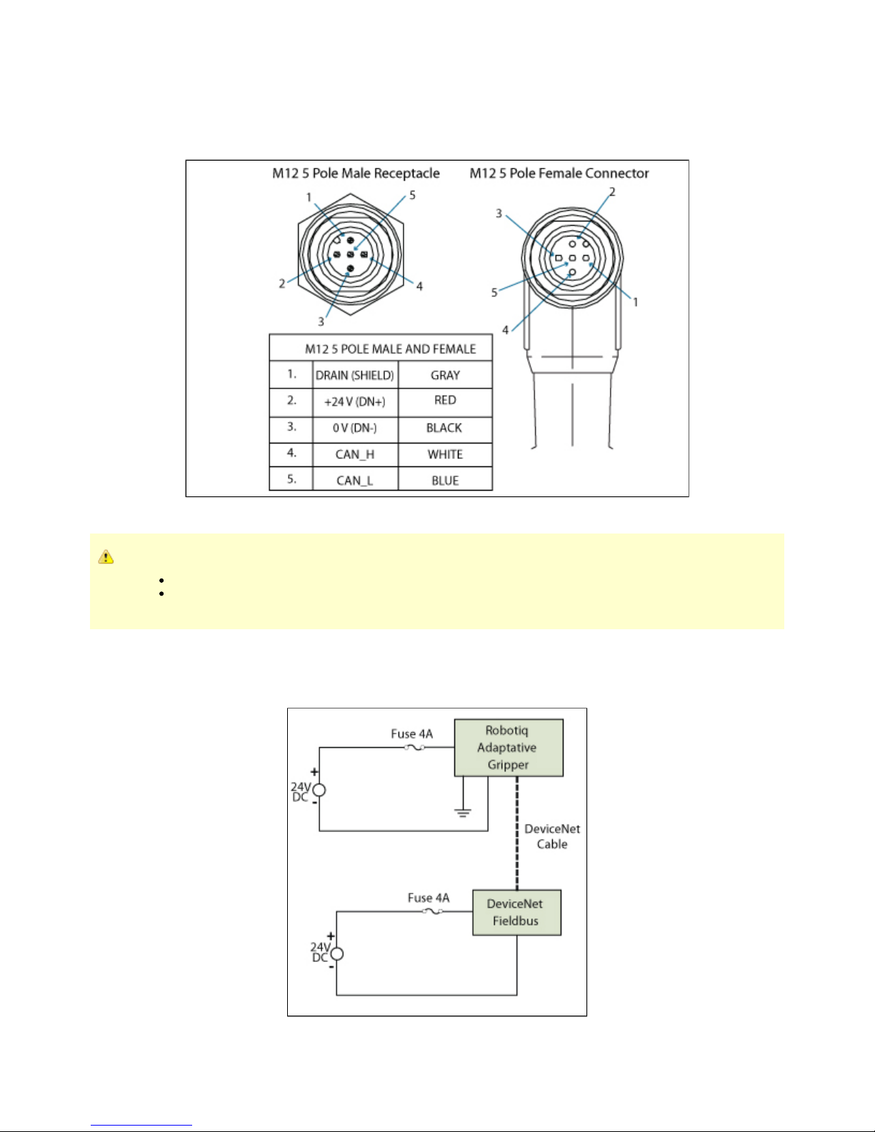
Figure 3.4.2.1 shows the pin-out for the DeviceNet communication protocol for the receptacle (male) present on the Adaptive Gripper S model
and the cable (female) provided with your Gripper.
Figure 3.4.2.1 – DeviceNet communication pinout.
Caution
There is no terminating resistor mounted in the Gripper.
The shield of the cable must be grounded in the robot controller.
The DeviceNet communication and the Adaptive Gripper S model use 24 V supply. Robotiq suggests to separate power supplies as shown in
Figure 3.4.2.2.
Figure 3.4.2.2 – Power connection diagram of the Adaptive Gripper S model using DeviceNet Fieldbus.
Robotiq inc. © 2011 14

Robotiq Adaptative Gripper, S model Instruction Manual
Factory settings for DeviceNet protocol:
IDENTIFICATION SETTINGS
Info Decimal value (base 10) Hexadecimal value (base 16)
Vendor ID : 283 0x0000011B
Product Code : 35 0x00000023
Serial Number : 0 0x00000000
Product Type : 12 0x0000000C
Major Revision : 1
Minor Revision : 1
Product Name : AG-DNS
BUS SETTING
MAC ID : 11
Baud Rate : 250 kBaud
DATA SETTINGS
Prod. Data Length : 16
Cons. Data Length : 16
Robotiq inc. © 2011 15

Robotiq Adaptative Gripper, S model Instruction Manual
CANopen communication protocol
Figure 3.4.2.3 shows the pin-out for the CANopen communication protocol for the receptacle (male) present on the Adaptive Gripper S model and
the cable (female) provided with your Gripper.
Figure 3.4.2.3 – CANopen communication pinout.
Caution
There is no terminating resistor mounted in the Gripper.
The shield of the cable must be grounded in the robot controller.
Factory settings for CANopen protocol:
IDENTIFICATION SETTINGS
Info Decimal value (base 10) Hexadecimal value (base 16)
Vendor ID : 68 0x00000044
Product Code : 1541540 0x001785A4
Revision Number : 131072 0x00020000
Serial Number : 0 0x00000000
Robotiq inc. © 2011 16
Robotiq Adaptative Gripper, S model Instruction Manual
BUS SETTING
Node Adress : 11
Baud Rate : 1 MBaud
DATA SETTINGS
Index Size
Send Object 0x2000 128
Receive Object 0x2200 128
Output Databytes 512
Input Databytes 512
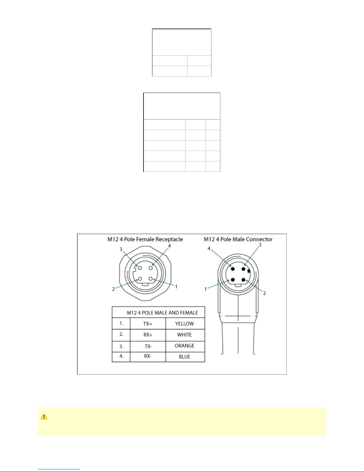
Real-time Ethernet communication protocol
Real-time Ethernet communication includes Ethernet/IP, EtherCAT and Modbus TCP/IP protocols.
See the Real-Time Ethernet pin-out diagram below (Figure 3.4.2.5) for the receptacle (male) present on the Adaptive Gripper S model and the
cable (female) provided with your Gripper.
Figure 3.4.2.5 – Real-time Ethernet communication pin-out.
Caution
The crossover on the RX/TX signals is made inside the Gripper.
Robotiq inc. © 2011 17

Robotiq Adaptative Gripper, S model Instruction Manual
Factory settings for each Ethernet protocols:
EtherCat EtherNet/IP Modbus TCP/IP
IDENTIFICATION SETTINGS
Vendor ID : 0x0000FFFF Vendor ID : 0x0000011B N / A
Product Code : 0x0000000B Product Code : 0x0000010D
Serial Number : 0x00000000 Product Type : 0x0000000C
Revision Number : 0x00000000 Major Revision : 1
Minor Revision : 1
Device Name : AG-EIS
EtherCat EtherNet/IP Modbus TCP/IP
BUS SETTING
N / A (see info note) IP Address : 192.168.1.11 IP Address : 192.168.1.11
Netmask : 255.255.255.0 Netmask : 255.255.255.0
Gateway : Disabled Gateway : Disabled
BootP : Disabled BootP : Disabled
DHCP : Disabled DHCP : Disabled
100Mbit : Enabled 100Mbit always on
Full Duplex: Enabled Full Duplex always on
Auto-neg : Enabled Auto-neg always on
Assembly Instance (input) : 101
Assembly Instance (output) : 100
Configuraton Instance : 1
Connection Type : Run/Idle Header
EtherCat EtherNet/IP Modbus TCP/IP
DATA SETTINGS
Input Data Bytes : 16 Prod. Data Length : 20 N / A
Output Data Bytes : 16 Cons. Data Length : 20 N / A
Info
Ethercat protocol uses inherent dynamic addressing thus bus settings cannot be customized
Robotiq inc. © 2011 18
Robotiq Adaptative Gripper, S model Instruction Manual
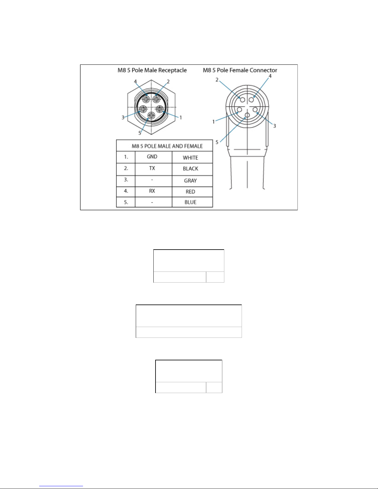
Serial communication protocol
Figure 3.4.2.6 shows the pin-out of the communication connectors when used in serial mode for the receptacle (male) present on the Adaptive
Gripper S model and the cable (female) provided with your Gripper.
Figure 3.4.2.6 – Serial communication pin-out.
Factory settings for Modbus RTU protocols:
IDENTIFICATION SETTINGS
Device : 9
BUS SETTING
See section for details4.9.1 Connection setup
DATA SETTINGS
Number of Register : 5000
Robotiq inc. © 2011 19

Robotiq Adaptative Gripper, S model Instruction Manual
4. Control
4.1 Generalities
Caution
This section applies to firmware 3.0 (grippers delivered after November 2011). For prior versions please see the documentation
archives.
The Robotiq Adaptive Gripper S model is controlled from the robot controller (see Figure 4.1) using an industrial protocol (EtherNet/IP, DeviceNet,
CANopen, EtherCat, etc.). The programming of the Gripper can be done with the of the robot or by offline programming.Teach Pendant
Info
For each Operation Mode, the operator can control the force and the speed of the fingers.
Unless individual control is selected, the fingers movement is always synchronized, movement is done with a single "Go
to requested position" command (the motion of each mechanical phalanx is done automatically).
Since the Robotiq Adaptive Gripper S model has its own internal controller, high-level commands such as "Go to requested position" are used to
control it. The embedded Robotiq Controller takes care of the regulation of the speed and the force prescribed, while the mechanical design of the
fingers automatically adapts to the shape of object(s).
Figure 4.1 – Adaptive Gripper S model connections.
4.2 Status overview
The Adaptive Gripper S-Model returns several registers of information to the robot controller:
Global Gripper Status - A global Gripper Status is available. This gives information such as which Operation Mode is currently active or
if the Gripper is closed or open.
Object Status - There is also an Object Status that let you know if there is an object in the Gripper and, in the affirmative, how many
fingers are in contact with it.
Fault Status - The Fault Status gives additional details about the cause of a fault.
Position Request Echo - The Gripper returns the position requested by the robot to make sure that the new command has been
received correctly.
Robotiq inc. © 2011 20

Robotiq Adaptative Gripper, S model Instruction Manual
1.
2.
Motor Encoder Status - The information of the encoders of the four motors is also available.
Current Status - The current of the motors can also be known. Since the torque of the motor is a linear function of the current, this gives
information about the force that is applied at the actuation linkage of the finger.
4.3 Control overview
The Gripper controller has an internal memory that is shared with the robot controller. One part of the memory is for the robot output, gripper
. The other part of the memory is for the robot input, (see Figure 4.3.1). Two types of actions can then be done byfunctionalities gripper status
the robot controller:
Write in the registers to activate ;robot output functionalities
Read in the registers to get the of the gripper. robot input status
Info
The Gripper must be initialized (activation bit) at power on. This procedure takes a few seconds and allows the gripper to be
calibrated against internal mechanical stops.
Figure 4.3.1 – Gripper memory shared with the robot controller.
4.4 Status LEDs
Three status LED lights provide general information about the Adaptive Gripper S model status. Figure 4.4.1 shows the LEDs and their locations.
Robotiq inc. © 2011 21

Robotiq Adaptative Gripper, S model Instruction Manual
Figure 4.4.1 – Status LEDs.
4.4.1 Supply LED
Color State Information
Blue Off Gripper is not power supplied
Blue On The Gripper is correctly supplied and the control board is running
4.4.2 Communication LED
Color State Information
Green Off No network detected
Green Blinking A network has been detected and no connection has been established
Green On A network has been detected and at least one connection is in the established state
4.4.3 Fault LED
Color State Information
Red Off No fault detected
Red On A minor fault occurred (or the Gripper si booting)
Red Blinking A major fault occurred
Info
A major fault refers to a situation where the Gripper must be reactivated.
Robotiq inc. © 2011 22

Robotiq Adaptative Gripper, S model Instruction Manual
4.5 Gripper register mapping
Caution
This section applies to firmware 3.0 (grippers delivered after November 2011). For prior versions please see the documentation
archives.
Info
Register format is Little Endian (Intel format), namely from LSB (Less Significant Bit) to MSB (Most Significant Bit).
Version 3 of the Adaptive Gripper S model firmware provides new functionalities such as the direct position control of the fingers via "go to"
commands. There is also additional advanced options such as the individual control of the fingers and scissor, the glove mode (when using the
Robotiq Glove) and the automatic centering of the fingers.
A Simplified Control Mode is available for users which do not intend to use the advanced option otherwise a register mapping for the Advanced
Control Mode containing all the gripper functionalities is also provided. From the gripper standpoint, there is no difference between the two
modes. The Simple Control Mode is only intended to ease the usage of the gripper for users who are only interested in the basic functionalities.
Warning
When using the Simplified Control Mode, it is important to fill the unused registers with zeros. Neglecting to do so would result in
the unwanted triggering of control options and could lead to a hazardous behavior of the Gripper.
Register mapping for the Simplified Control Mode
Register Robot Output / Functionalities Robot Input / Status
Byte 0 ACTION REQUEST GRIPPER STATUS
Byte 1 00000000 OBJECT DETECTION
Byte 2 00000000 FAULT STATUS
Byte 3 POSITION REQUEST POS. REQUEST ECHO
Byte 4 SPEED FINGER A POSITION
Byte 5 FORCE FINGER A CURRENT
Byte 6 00000000 NOT USED IN SIMPLE MODE
Byte 7 00000000 FINGER B POSITION
Byte 8 00000000 FINGER B CURRENT
Byte 9 00000000 NOT USED IN SIMPLE MODE
Byte 10 00000000 FINGER C POSITION
Byte 11 00000000 FINGER C CURRENT
Byte 12 00000000 NOT USED IN SIMPLE MODE
Byte 13 00000000 SCISSOR POSITION
Byte 14 00000000 SCISSOR CURRENT
Byte 15 RESERVED RESERVED
Robotiq inc. © 2011 23
Robotiq Adaptative Gripper, S model Instruction Manual
Register mapping for the Advanced Control Mode
Register Robot Output / Functionalities Robot Input / Status
Byte 0 ACTION REQUEST GRIPPER STATUS
Byte 1 GRIPPER OPTIONS OBJECT DETECTION
Byte 2 GRIPPER OPTIONS #2 (EMPTY) FAULT STATUS
Byte 3 POSITION REQUEST (FINGER A IN INDIVIDUAL MODE) POS. REQUEST ECHO
Byte 4 SPEED (FINGER A IN INDIVIDUAL MODE) FINGER A POSITION
Byte 5 FORCE (FINGER A IN INDIVIDUAL MODE) FINGER A CURRENT
Byte 6 FINGER B POSITION REQUEST FINGER B POS. REQUEST ECHO
Byte 7 FINGER B SPEED FINGER B POSITION
Byte 8 FINGER B FORCE FINGER B CURRENT
Byte 9 FINGER C POSITION REQUEST FINGER C POS. REQUEST ECHO
Byte 10 FINGER C SPEED FINGER C POSITION
Byte 11 FINGER C FORCE FINGER C CURRENT
Byte 12 SCISSOR POSITION REQUEST SCISSOR POS. REQUEST ECHO
Byte 13 SCISSOR SPEED SCISSOR POSITION
Byte 14 SCISSOR FORCE SCISSOR CURRENT
Byte 15 RESERVED RESERVED
4.6 Robot output registers & functionalities
Caution
This section applies to firmware 3.0 (grippers delivered after November 2011). For prior versions please see the documentation
archives.
Info
Register format is Little Endian (Intel format), namely from LSB (Less Significant Bit) to MSB (Most Significant Bit).
Register: ACTION REQUEST
Address: Byte 0
Bit Name Description
0 rACT
0 – Reset Gripper
1 – Activate Gripper (Must stay on after activation routine is completed)
1
rMOD
00 – Go to Basic Mode
10 – Go to Pinch Mode
01 – Go to Wide Mode
11 – Go to Scissor Mode
2
3 rGTO
0 – Stop
1 – Go to Requested Position
4 rATR
0 – Normal
1 – Automatic release
5-7 rRS0 Reserved
Robotiq inc. © 2011 24

Robotiq Adaptative Gripper, S model Instruction Manual
: First action to be made prior to any other actions, bit will initialize the Adaptive Gripper. Clear to reset Gripper and fault status.rACT rACT rACT
Caution
rACT bit must stay on afterwards for any other action to be performed.
: Changes the Gripper . When the Grasping Mode is changed, the Gripper first opens completely to avoid interferencesrMOD Grasping Mode
between the fingers then go to the selected mode. This option is ignored if the bit is set (individual control of the scissor motion option). rICS
: The "Go To" action moves the Gripper fingers to the requested position using the configuration defined by the other registers and the rGTO
bits. The only motions performed without the bit are the activation, the mode change and the automatic release routines. rMOD rGTO
: Automatic Release routine action slowly open the Gripper fingers until all motions axes reach their mechanical limits. After the motion isrATR
completed, the Gripper sends a fault signal and needs to be reinitialized before any other motion is performed. The bit overrides all otherrATR
commands excluding the activation bit ( ).rACT
Caution
The Automatic Release is meant to disengage the Gripper after an emergency stop of the robot. The Automatic Release is not
intended to be used under normal operating conditions.
Register: GRIPPER OPTIONS
Address: Byte 1
Bit Name Description
0 rGLV
0 – Normal
1 – Enable Glove Mode (use only if a glove provided by Robotiq is installed on the Gripper)
1 rAAC
0 – Normal
1 – Enable Automatic Auto-Centering
2 rICF
0 – Normal
1 – Enable Individual Control of Fingers A, B and C
3 rICS
0 – Normal
1 – Enable Individual Control of Scissor. Disable Mode Selection.
4-7 rRS1 Reserved
rGLV: The Glove Mode option must be on when using the Robotiq Glove on the Adaptive Gripper. Using the Robotiq Glove without this option
could result in a hazardous behavior of the Gripper. . This option is not implemented in the beta version of the firmware
: The Automatic Centering option synchronizes the Gripper fingers in order to automatically center the object it seizes. This option requiresrAAC
that fingers B and C have the same position request and velocity. It is not intended to be used in the scissor mode. This option is currently in a
. beta version and might be modified in future versions of the firmware
: In Individual Control of Fingers mode each finger receives its own command (position request, speed and force) unless the Gripper is in therICF
Scissor Grasping Mode and the Independent Control of Scissor ( ) is not activated. Please refer to the (Position Request) registerrICS rPRA
description for information about the reachable positions of the fingers.
Caution
As soon as the bit is set, the fingers will move towards the target defined by the position request bytes. To avoid unwantedrICF
motion of the fingers, it is preferable to define the position requests before setting the bit. It is also possible to clear the rICF
bit, configure the registers according to the desired motion and then set the bit to start the motion.rGTO rGTO
: In Individual Control of Scissor the scissor axis moves independently from the Grasping mode. When this option is selected, the bitsrICS rMOD
(Grasping Mode) are ignored as the scissor axis position is defined by the (Position Request for the Scissor axis) register.rPRS
Robotiq inc. © 2011 25

Robotiq Adaptative Gripper, S model Instruction Manual
Caution
To avoid geometrical interference between fingers B and C, the reachable positions for the scissor axis is reduced if the
Individual Control of Scissor option is selected. Please refer to the (Position Request) register description for morerPRA
information about the reachable positions of the scissor axis.
Register: GRIPPER OPTIONS 2
Address: Byte 2
Bit Name Description
0 – 7 rRS2 Reserved
Register: POSITION REQUEST (FINGER A IN INDIVIDUAL MODE)
Address: Byte 3
Bit Name Description
0 – 7 rPRA
Set Position Request for the Gripper (finger A in individual mode).
0x00 (Minimum position) to 0xFF (Maximum position)
This register is used to set the Adaptive Gripper fingers target position (or finger A only if bit is set). The positions 0x00 and 0xFF correspondrICF
respectively to the fully opened and fully closed mechanical stops. Figure 4.6.1 represents the reachable workspace of the fingers and scissor
axis, values shown are valid only if the Glove Mode option is not selected and are shown as a reference only. Note that the finger position on the
figure represents the maximum value for the three fingers. Also, note that the fully opened and fully closed software limits are not shown on the
figure for simplicity.
Caution
In order to protect the Gripper from geometric interferences, several software limits are implemented and therefore some
positions are not reachable. When a finger reaches the software limit, the Gripper status will indicate that the requested position
was reached. This is because the requested position is internally replaced by the software limit.
Figure 4.6.1 Reachable workspace of the fingers and scissor axis.
Robotiq inc. © 2011 26

Robotiq Adaptative Gripper, S model Instruction Manual
Register: SPEED (FINGER A IN INDIVIDUAL MODE)
Address: Byte 4
Bit Name Description
0 – 7 rSPA
Set Grasping Speed of the Gripper (finger A in individual mode).
0x00 (Minimum velocity) to 0xFF (Maximum velocity)
This register is used to setup the Gripper closing or opening speed (or finger A only if bit is set) in real time, however, setting a speed will notrICF
initiate a motion.
Info
0x00 speed does not mean absolute zero speed. It is the minimum speed of the Gripper.
Register: FORCE (FINGER A IN INDIVIDUAL MODE)
Address: Byte 5
Bit Name Description
0 – 7 rFRA
Set Gripping Force
0x00 (Minimum force) to 0xFF (Maximum force)
The the force setting defines the final grasping force of the Adaptive Gripper (or finger A only if bit is set). The force will fix maximum currentrICF
sent to the motors while in motion. For each finger, if the current limit is exceeded, the finger stops and triggers an object detection notification.
Info
Force setting is overridden for a small distance when the motion is initiated. Also, note that 0x00 force does not mean zero
force; it is the minimum force that the Gripper can apply.
Register: FINGER B POSITION REQUEST
Address: Byte 6
Bit Name Description
0 – 7 rPRB
Set Position Request for finger B.
0x00 (Minimum position) to 0xFF (Maximum position)
This register is used to set the finger B target position. It is only considered if the Individual Control of Finger option is selected (bit is set).rICF
Please refer to (position request) register for more information.rPRA
Register: FINGER B SPEED
Address: Byte 7
Bit Name Description
0 – 7 rSPB
Set Grasping Speed for finger B.
0x00 (Minimum velocity) to 0xFF (Maximum velocity)
This register is used to set finger B speed. It is only considered if the Individual Control of Finger option is selected (bit is set). Please refer torICF
(speed) register for more information.rSPA
Register: FINGER B FORCE
Address: Byte 8
Bit Name Description
0 – 7 rFRB
Set Gripping Force for finger B.
0x00 (Minimum force) to 0xFF (Maximum force)
Robotiq inc. © 2011 27

Robotiq Adaptative Gripper, S model Instruction Manual
This register is used to set finger B force. It is only considered if the Individual Control of Finger option is selected (bit is set). Please refer to rICF
(force) register for more information.rFRA
Register: FINGER C POSITION REQUEST
Address: Byte 9
Bit Name Description
0 – 7 rPRC
Set Position Request for finger C.
0x00 (Minimum position) to 0xFF (Maximum position)
This register is used to set the finger C target position. It is only considered if the Individual Control of Finger option is selected (bit is set).rICF
Please refer to (position request) register for more information.rPRA
Register: FINGER C SPEED
Address: Byte 10
Bit Name Description
0 – 7 rSPC
Set Grasping Speed for finger C.
0x00 (Minimum velocity) to 0xFF (Maximum velocity)
This register is used to set finger C speed. It is only considered if the Individual Control of Finger option is selected (bit is set). Please refer torICF
(speed) register for more information.rSPA
Register: FINGER C FORCE
Address: Byte 11
Bit Name Description
0 – 7 rFRC
Set Gripping Force
0x00 (Minimum force) to 0xFF (Maximum force)
This register is used to set finger C force. It is only considered if the Individual Control of Finger option is selected (bit is set). Please refer to rICF
(force) register for more information.rFRA
Register: SCISSOR POSITION REQUEST
Address: Byte 12
Bit Name Description
0 – 7 rPRS
Set Position Request for the scissor axis.
0x00 (Minimum position) to 0xFF (Maximum position)
This register is used to set the scissor axis target position. It is only considered if the Individual Control of Scissor option is selected (bit isrICS
set). Please refer to (position request) register for more information.rPRA
Register: SCISSOR SPEED
Address: Byte 13
Bit Name Description
0 – 7 rSPS
Set Grasping Speed for the scissor axis.
0x00 (Minimum velocity) to 0xFF (Maximum velocity)
This register is used to set the scissor axis speed. It is only considered if the Individual Control of Scissor option is selected (bit is set).rICS
Please refer to (speed) register for more information.rSPA
Register: SCISSOR FORCE
Address: Byte 14
Bit Name Description
0 – 7 rFRS
Set Gripping Force for the scissor axis
0x00 (Minimum force) to 0xFF (Maximum force)
Robotiq inc. © 2011 28

Robotiq Adaptative Gripper, S model Instruction Manual
This register is used to set the scissor axis force. It is only considered if the Individual Control of Scissor option is selected (bit is set). PleaserICS
refer to (force) register for more information. rFRA
4.7 Robot input registers & status
Caution
This section applies to firmware 3.0 (grippers delivered after November 2011). For prior versions please see the documentation
archives.
Info
Register format is Little Endian (Intel format), namely from LSB (Less Significant Bit) to MSB (Most Significant Bit).
Register: GRIPPER STATUS
Address: Byte 0
Bit Name Description
0 gACT
Echo of the rACT bit (Activation bit):
0 – Gripper reset
1 – Gripper activation
1
gMOD
Echo of the rMOD bits (Grasping Mode request)
00 – Basic Mode
10 – Pinch Mode
01 – Wide Mode
11 – Scissor Mode
2
3 gGTO
0 – Stopped (or performing activation/grasping mode change/automatic release)
1 – Go to Position Request
4
gIMC
00 – Gripper is in reset (or automatic release) state. see Fault Status if Gripper is activated.
10 – Activation in progress.
01 – Mode change in progress.
11 – Activation an mode change are completed.
5
6
gSTA
00 – Gripper is in motion towards requested position (only meaningful if gGTO = 1)
01 – Gripper is stopped. One or two fingers stopped before requested position
10 – Gripper is stopped. All fingers stopped before requested position
11 --Gripper is stopped. All fingers reached requested position
7
Register: OBJECT STATUS
Address: Byte 1
Robotiq inc. © 2011 29

Robotiq Adaptative Gripper, S model Instruction Manual
Bit Name Description
0
gDTA
00 – Finger A is in motion (only meaningful if gGTO = 1)
10 – Finger A has stopped due to a contact while opening
01 – Finger A has stopped due to a contact while closing
11 – Finger A is at requested position
1
2
gDTB
00 – Finger B is in motion (only meaningful if gGTO = 1)
10 – Finger B has stopped due to a contact while opening
01 – Finger B has stopped due to a contact while closing
11 – Finger B is at requested position
3
4
gDTC
00 – Finger C is in motion (only meaningful if gGTO = 1)
10 – Finger C has stopped due to a contact while opening
01 – Finger C has stopped due to a contact while closing
11 – Finger C is at requested position
5
6
gDTS
00 – Scissor is in motion (only meaningful if gGTO = 1)
01 – Scissor has stopped due to a contact while opening
10 – Scissor has stopped due to a contact while closing
11 – Scissor is at requested position.
7
When a contact is detected, the corresponding axis will stop until one of these conditions is met: a new position request is commanded in the
opposite direction, the requested force level is increased or the bit is cleared and set again. rGTO
Warning
Resetting the contact detection repeatedly at high frequency using the bit may cause a major failure of the Gripper. ThisrGTO
is not considered a normal usage of the Gripper and it is not recommended by Robotiq.
Caution
The object detection is precise only to the order of a few mm. In some circumstances object detection may not detect an object
even if it is successfully grasped. For example, picking up a thin object in a fingertip grip may be successful without object
detection occurring. For such reasons, use this feature with caution. In such applications the "Gripper is stopped" status of
register is sufficient to proceed to the next step of the routine.gSTA
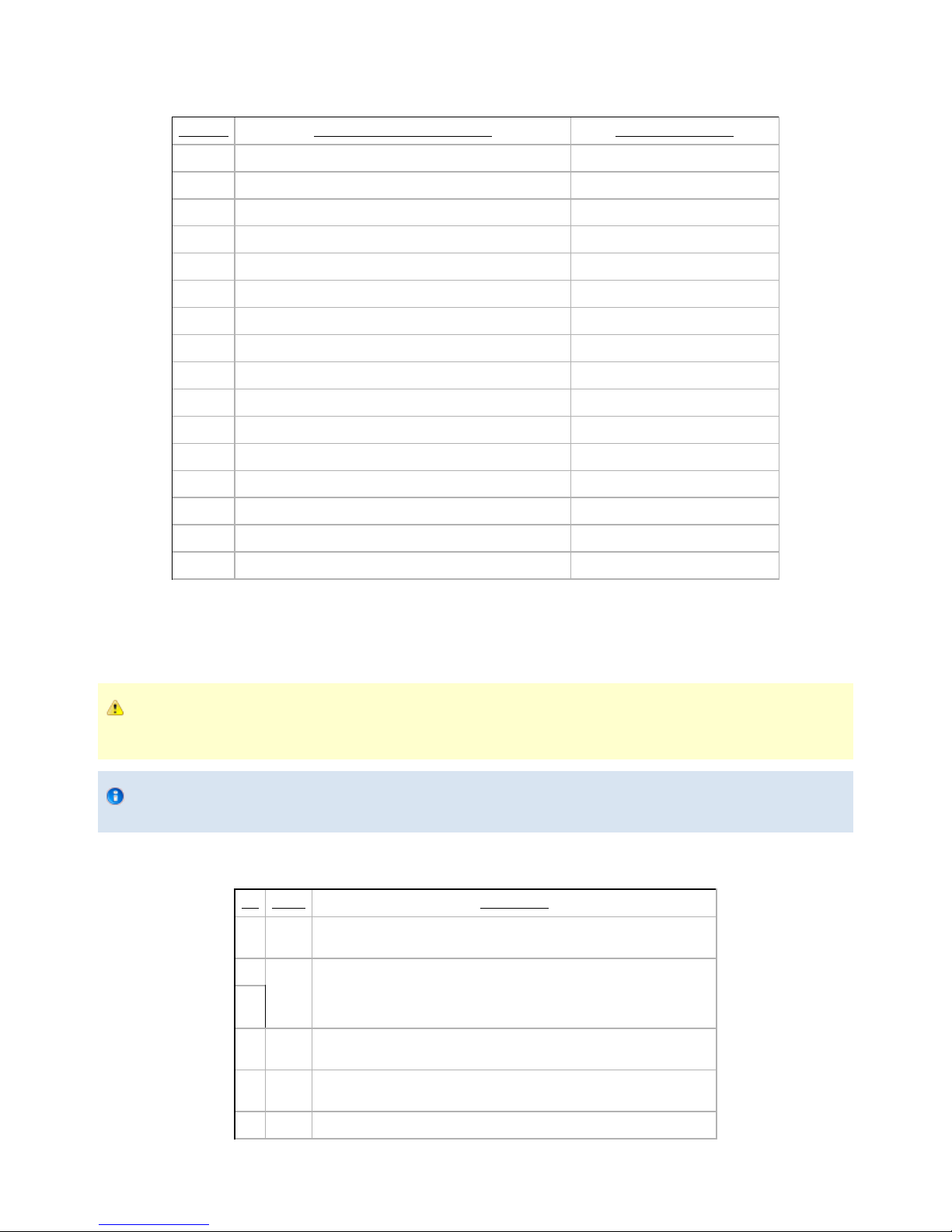
Register: FAULT STATUS
Address: Byte 2
Bit Name Description
0 – 3 gFLT
0x00 – No Fault
Priority Fault
0x05 – Action delayed, activation (reactivation) must be completed prior to action
0x06 – Action delayed, mode change must be completed prior to action
0x07 – The activation bit must be set prior to action
Minor Fault (red LED continuous)
0x09 – The communication chip is not ready (may be booting)
0x0A – Changing mode fault, interferences detected on Scissor (for less than 20 sec)
0x0B – Automatic release in progress
Major Fault (red LED blinking) – Reset is required
0x0D – Activation fault, verify that no interference or other error occured
0x0E – Changing mode fault, interferences detected on Scissor (for more than 20 sec)
0x0F – Automatic release completed. Reset and activation is required.
4 – 7 gRS1 Reserved (zeros)
Register: POSITION REQUEST ECHO (FINGER A IN INDIVIDUAL MODE)
Address: Byte 3
Robotiq inc. © 2011 30

Robotiq Adaptative Gripper, S model Instruction Manual
Bit Name Description
0 – 7 gPRA
Echo of the requested position for the Gripper (or finger A in individual mode)
0x00 (Full Opening) to 0xFF (Full Closing)
Register: FINGER A POSITION
Address: Byte 4
Bit Name Description
0 – 7 gPOA
Position of Finger A
0x00 (Fully opened) to 0xFF (Fully closed)
Register: FINGER A CURRENT
Address: Byte 5
Bit Name Description
0 – 7 gCUA
Current of Finger A
0.1 * Current (in mA)
Register: FINGER B POSITION REQUEST ECHO
Address: Byte 6
Bit Name Description
0 – 7 gPRB
Echo of the requested position for finger B
0x00 (Full Opening) to 0xFF (Full Closing)
Register: FINGER B POSITION
Address: Byte 7
Bit Name Description
0 – 7 gPOB
Position of Finger B
0x00 (Fully opened) to 0xFF (Fully closed)
Register: FINGER B CURRENT
Address: Byte 8
Bit Name Description
0 – 7 gCUB
Current of Finger B
0.1 * Current (in mA)
Register: FINGER C POSITION REQUEST ECHO
Address: Byte 9
Bit Name Description
0 – 7 gPRC
Echo of the requested position for finger C
0x00 (Full Opening) to 0xFF (Full Closing)
Register: FINGER C POSITION
Robotiq inc. © 2011 31

Robotiq Adaptative Gripper, S model Instruction Manual
Address: Byte 10
Bit Name Description
0 – 7 gPOC
Position of Finger C
0x00 (Fully opened) to 0xFF (Fully closed)
Register: FINGER C CURRENT
Address: Byte 11
Bit Name Description
0 – 7 gCUC
Current of Finger C
0.1 * Current (in mA)
Register: SCISSOR POSITION REQUEST ECHO
Address: Byte 12
Bit Name Description
0 – 7 gPRS
Echo of the requested position for the scissor axis
0x00 (Full Opening) to 0xFF (Full Closing)
Register: SCISSOR POSITION
Address: Byte 13
Bit Name Description
0 – 7 gPOS
Position of the scissor axis
0x00 (Fully opened) to 0xFF (Fully closed)
Register: SCISSOR CURRENT
Address: Byte 14
Bit Name Description
0 – 7 gCUS
Current for the scissor axis
0.1 * Current (in mA)
Robotiq inc. © 2011 32
Robotiq Adaptative Gripper, S model Instruction Manual
4.8 Example
Figure 4.8.1 : Example of Adaptive Gripper S model registers.
4.9 MODBUS RTU communication protocol
The Robotiq Adaptive Gripper S model can be controlled over RS232 using the Modbus RTU protocol. This section is intended to provide
guidelines for setting up a Modbus scanner that will adequately communicate with the gripper.
For a general introduction to Modbus RTU and for details regarding the CRC algorithm, the reader is invited to read the Modbus over serial line
specification and implementation guide available . http://www.modbus.org/docs/Modbus_over_serial_line_V1.pdf
For debug purposes, the reader is also invited to download one of many free Modbus scanners such as the from CAS Modbus Scanner Chipkin
available .Automation Systems http://www.chipkin.com/cas-modbus-scanner
Robotiq inc. © 2011 33

Robotiq Adaptative Gripper, S model Instruction Manual
4.9.1 Connection setup
The following table describes the connection requirement for controlling the Robotiq Adaptive Gripper S model using the Modbus RTU protocol.
Physical Interface RS232
Baud Rate 115,200 bps
Data Bits 8
Stop Bit 1
Parity None
Number Notation Hexadecimal
Supported Functions
Read Holding Registers (FC03)
Preset Single Register (FC06)
Preset Multiple Registers (FC16)
Exception Responses Not supported
Slave ID 0x0009 (9)
Robot Output / Gripper Input First Register 0x03E8 (1000)
Robot Input / Gripper Output First Register 0x07D0 (2000)
Each register (word - 16 bits) of the Modbus RTU protocol is composed of registers (bytes – 8 bits) from the Robotiq Adaptive Gripper S. The2
first Gripper output Modbus register (0x07D0) is composed from the first Robotiq Adaptive Gripper S registers (byte 0 and byte 1).2
4.9.2 Read holding registers (FC03)
Function code 03 (FC03) is used for reading the status of the Gripper (robot input). Examples of such data are Gripper status, object status, finger
position, etc.
Ex: This message asks for register 0x07D0 (2000) and register 0x07D1 (2001) which contains Gripper Status, Object Detection, Fault Status and
Position Request Echo.
Request is:
09 03 07 D0 00 02 C5 CE
where
09 SlaveID
03 Function Code 03 (Read Holding Registers)
07D0 Address of the first requested register
0002 Number of registers requested (2)
C5CE Cyclic Redundancy Check (CRC)
Response is:
09 03 04 E0 00 00 00 44 33
where
Robotiq inc. © 2011 34

Robotiq Adaptative Gripper, S model Instruction Manual
09 SlaveID
03 Function Code 03 (Read Holding Registers)
04 Number of data bytes to follow (2 registers x 2 bytes/register = 4 bytes)
E000 Content of register 07D0
0000 Content of register 07D1
4433 Cyclic Redundancy Check (CRC)
Note
The Adaptive Gripper register values are updated at a 200Hz frequency. It is therefore recommanded to send FC03 commands
with a minimum delay of 5ms between them.
4.9.3 Preset single register (FC06)
Function code 06 (FC06) is used to activate functionalities of the Gripper (robot output). Examples of such data are action request, velocity, force,
etc.
Ex: This message requests to initialize the Gripper by setting register 0x03E8 (1000), which contains Action Request and Gripper Options, to
0x0100.
Request is:
09 06 03 E8 01 00 09 62
where
09 SlaveID
06 Function Code 06 (Preset Single Register)
03E8 Address of the register
0100 Value to write
0962 Cyclic Redundancy Check (CRC)
Response is an echo:
09 06 03 E8 01 00 09 62
where
09 SlaveID
06 Function Code 06 (Preset Single Register)
03E8 Address of the register
0100 Value written
0962 Cyclic Redundancy Check (CRC)
4.9.4 Preset multiple registers (FC16)
Function code 06 (FC16) is used to activate functionalities of the Gripper (robot output). Examples of such data are action request, speed, force,
etc.
Ex: This message requests to set position request, speed and force of the Gripper by setting register 0x03E9 (1001) and 0x03EA.
Request is:
09 10 03 E9 00 02 04 60 E6 3C C8 EC 7C
Robotiq inc. © 2011 35

Robotiq Adaptative Gripper, S model Instruction Manual
where
09 SlaveID
10 Function Code 16 (Preset Multiple Registers)
03E9 Address of the first register
0002 Number of registers to write
04 Number of data bytes to follow (2 registers x 2 bytes/register = 4 bytes)
00E6 Value to write to register 0x03E9
3CC8 Value to write to register 0x03EA
EC7C Cyclic Redundancy Check (CRC)
Response is:
09 10 03 E9 00 02 91 30
where
09 SlaveID
10 Function Code 16 (Preset Multiple Registers)
03E9 Address of the first register
0002 Number of written
9130 Cyclic Redundancy Check (CRC)
4.10 MODBUS TCP communication protocol
The Robotiq Adaptive Gripper S model can be controlled using the Modbus TCP protocol. This section is intended to provide guidelines for setting
up a Modbus TCP communication to adequately send commands and read inputs from the gripper.
For a general introduction to Modbus TCP and to understand its differences from Modbus RTU, the reader is invited to read the information
provided on the following website:
http://www.simplymodbus.ca/TCP.htm
4.10.1 Connection Setup
The following table describes the connection requirement for controlling the Robotiq Adaptive Gripper S using the Modbus TCP protocol.
Required protocol TCP/IP
Port 502
Gripper IP address Configurable (most grippers are shipped with the 192.168.1.11 address)
Supported Functions
Read Input Registers (FC04)
Preset Multiple Registers (FC16)
UnitID 0x0002 (2)
Robot Output / Gripper Input First Register 0x0000 (0000)
Robot Input / Gripper Output First Register 0x0000 (0000)
Each register (word - 16 bits) of the Modbus TCP protocol is composed of registers (bytes – 8 bits) from the Robotiq Adaptive Gripper. The first2
Gripper output Modbus register (0x0000) is composed from the first Robotiq Adaptive Gripper registers (byte 0 and byte 1).2
Robotiq inc. © 2011 36

Robotiq Adaptative Gripper, S model Instruction Manual
4.10.2 Read Input Registers (FC04)
Function code 04 (FC04) is used for reading the status of the Gripper (robot input). Examples of such data are Gripper status, object status, finger
position, etc.
Ex: This message asks for registers 0x0000 (0000) to 0x0006 (0006) which contain all the robot input statuses except for the scissor axis.
Request is:
01 00 00 00 00 06 02 04 00 00 00 06
where
01 00 Transaction identifier
00 00 Protocol identifier
00 06 Length
02 UnitID
04 Function 04 (Read input registers)
00 00 Address of the first register
00 06 Word count
Response is:
01 00 00 00 00 0f 02 04 0c e9 00 00 00 06 06 06 8a 00 00 00 00
where
01 00 Transaction identifier
00 00 Protocol identifier
00 0f Length
02 UnitID
04 Function 04 (Read input registers)
0c The number of data bytes to follow
e9 00 00 00 06 06 06 8a 00 00 00 00 Data
Note
The Adaptive Gripper register values are updated at a 200Hz frequency. It is therefore recommanded to send FC04 commands
with a minimum delay of 5ms between them.
4.10.3 Preset Multiple Registers (FC16)
Function code 06 (FC16) is used to activate functionalities of the Gripper (robot output). Examples of such data are action request, position
request, speed, force, etc.
Ex: This message requests to set several options of the Gripper by setting registers from 0x0000 (0000) to 0x0003.
Request is:
01 00 00 00 00 0d 02 10 00 00 00 03 06 09 00 64 64 00 ff
Robotiq inc. © 2011 37

Robotiq Adaptative Gripper, S model Instruction Manual
where
01 00 Transaction identifier
00 00 Protocol identifier
00 0d Length
02 UnitID
10 Function 16 (Preset multiple registers)
00 00 Address of the first register
00 03 The number of registers to write
06 The number of data bytes to follow
09 00 00 64 00 ff Data
Response is:
01 00 00 00 00 06 02 10 00 00 00 03
where
01 00 Transaction identifier
00 00 Protocol identifier
00 06 Length
02 UnitID
10 Function 16 (Preset multiple registers)
00 00 Address of the first register
00 03 The number of registers written
Robotiq inc. © 2011 38
Robotiq Adaptative Gripper, S model Instruction Manual
5. User Interface
The following section describes the Robotiq User Interface software provided with the Adaptive Gripper S-Model.
The User Interface is designed to allow Adaptive Gripper S:
Testing.
Demo mode.
Xbox Remote control mode.
Communication options configuration.
Note
Robotiq User Interface Software is designed for the testing and demo control of the Adaptive Gripper S-Model. It is not a
production control software.
visit to get the latest installer of the Robotiq User Interface for S-Modelhttp://support.robotiq.com
Figure 5.1 Main screen of the Robotiq User Interface.
5.1 Requirements
To use this version of the Robotiq User Interface, you will need:
The Adaptive Gripper S model and its power cable (see section)Wiring
A computer with
Windows XP or newer
At least 50MB of main memory
A USB port and/or an Ethernet port
A 24V power source for the Gripper
A small Phillips screwdriver
A USB 2.0 Micro-B or a USB 2.0 Micro-A cable. (Connection via the USB use Modbus RTU)
Optional: An Ethernet communication connector for Modbus TCP provided by Robotiq. (Connection via Ethernet uses Modbus TCP), an
Xbox controller
Info
The USB cable that is needed for the configuration of the communication protocol is provided with the Adaptive Gripper.
Note
Ethernet Option: You will only have the Ethernet communication connector provided with your Gripper if you have the Modbus
TCP option.
5.2 Installation
Robotiq inc. © 2011 39

Robotiq Adaptative Gripper, S model Instruction Manual
1.
2.
3.
4.
1.
2.
3.
4.
To install the Robotiq User Interface software:
Launch the Robotiq User Interface installer from "Robotiq User Interface Setup.exe" provided by Robotiq.
Choose the installer language and click "Ok".
Follow the setup steps until you can click "Install".
Tip
You can leave the settings on default or choose an installation directory of your own.
After installation is completed you can launch the Robotiq User Interface, if you do not have the required drivers for the USB connection
of the Gripper, please select the box shown in figure 5.2.1.
Warning
To use the Modbus RTU communication via the USB port, you need to select the driver installation shown in figure
5.2.1
Figure 5.2.1 Completing the installation of Robotiq User Interface
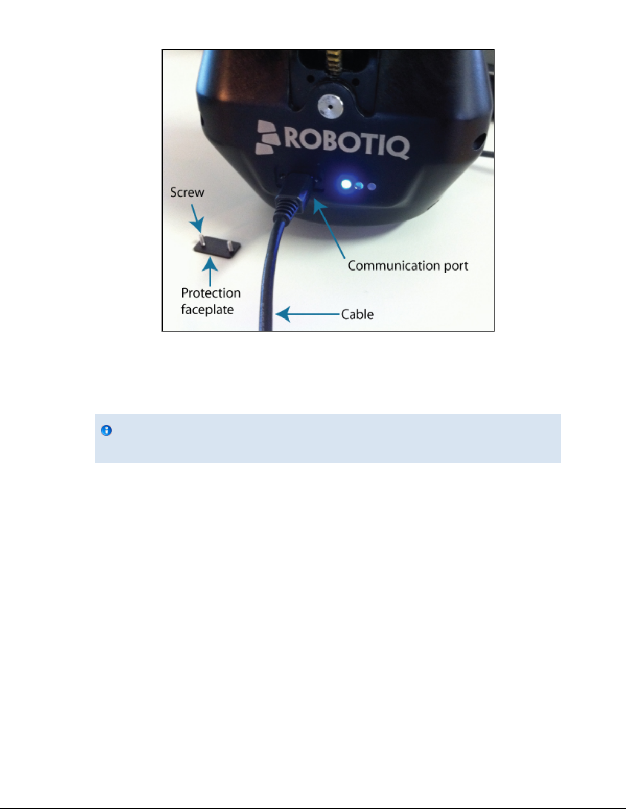
In order to connect the Adaptive Gripper via USB for Modbus RTU:
Unplug the Gripper from the power source by disconnecting the power cable from the Gripper.
Remove the USB port panel by unscrewing the two screws (shown in Figure 5.2.2). A Phillips screwdriver is needed.
Connect the Gripper to your computer with a USB 2.0 Micro-B or a USB 2.0 Micro-A cable.
Info
The USB cable needed is provided with the Adaptive Gripper.
Reconnect the power connector to the power receptacle and power up the Gripper with a 24V power source (not included) as described
in the section . Wiring
Robotiq inc. © 2011 40
Robotiq Adaptative Gripper, S model Instruction Manual
1.
2.
3.
1.
2.
3.
4.
5.
Figure 5.2.2: Unscrewing the USB port panel and connecting the USB 2.0 Micro cable.
To connect the Adaptive Gripper via Ethernet port for Modbus TCP or Modbus RTU:
Unplug the Gripper from the power source by disconnecting the power cable from the Gripper.
Connect the Gripper to your computer with the Ethernet communication connector.
Info
The Ethernet or Serial cable needed is provided with the Adaptive Gripper if the Gripper has the Modbus TCP or
Modbus RTU communication option.
Reconnect the power connector to the power receptacle and power up the Gripper with a 24V power source (not included) as described
in the section.Wiring
See the following sections for a description of the User Interface and its usage.
If you are connected through the USB port and the configuration is finished, follow these steps to acess the normal usage of the Gripper:
Disconnect the Gripper with the button found in the User Interface menu or simply quit the program.Disconnect
Unplug the Gripper from the power source by disconnecting the power cable from the Gripper.
Unplug the Gripper from your PC by removing the USB cable.
Replace the USB port panel by screwing back the two screws (shown in figure 5.2.2). A phillips screwdriver is needed.
Reconnect the power and communication cables to the Gripper as described in the section. Wiring
5.3 UI Description
When you first start the Robotiq User Interface you need to set the connection mode you will use (see Figure 5.3.1). Choose between Modbus
RTU or Modbus TCP according to your connection options. If you do not know what connection you will be using simply close the pop-up window
(you can connect later).
Robotiq inc. © 2011 41

Robotiq Adaptative Gripper, S model Instruction Manual
Figure 5.3.1 Connection options available on start-up of the Robotiq User Interface.
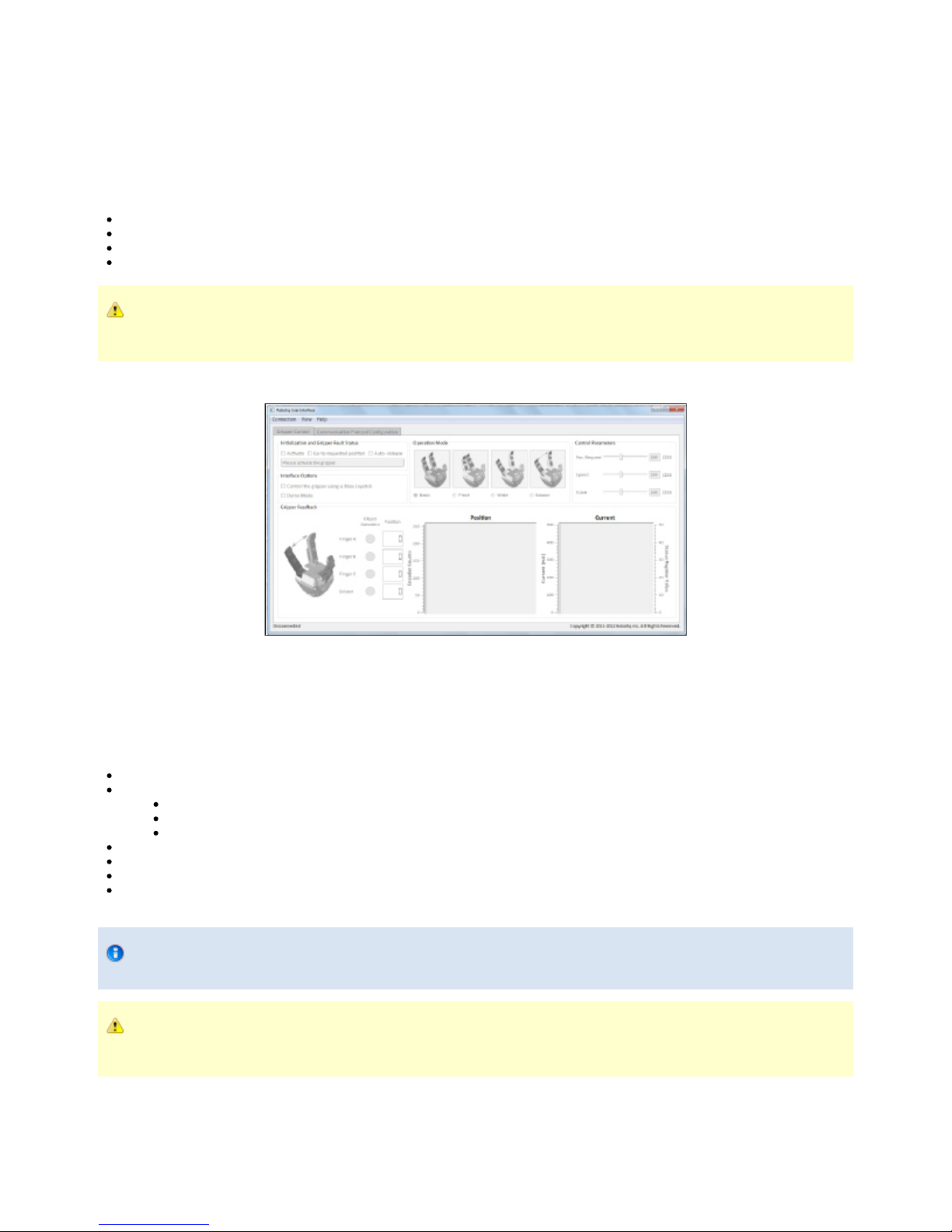
Once you choose the connection mode, the first tab becomes activated (see Figure 5.3.2).
The first tab is the Gripper Control tab (detailed in ), it can be split into the following:section 5.5
Initialization and Gripper Fault Status
Interface Options
Operation Mode
Control Parameters
Gripper Feedback
Menus: Connection, View and Help
Figure 5.3.2 Gripper Control tab description.
The Communication Protocol Configuration tab (detailed in ) will be split into :section 5.6
Device Identity
Protocol
Data
Robotiq inc. © 2011 42

Robotiq Adaptative Gripper, S model Instruction Manual
Figure 5.3.3 Communication Protocol Control configuration tab (shown with Ethernet/IP)
5.4 Connection
If the connection protocol was properly chosen using the pop-up window, the connection will be automatically established unless the status label
(lower left part of the main window) displays "Connection failed".
If a connection has not been established yet, you can manually connect to the Gripper via the connection menu.
The connection menu allows you to :
Connect via Modbus RTU
Connect via Modbus TCP
Disconnect
Note that you must choose the right connection option (see section 5.2) for your Gripper.
5.4.1 Modbus RTU
A connection via Modbus RTU can be established with all Robotiq Adaptive Grippers S models via the USB port panel or via the communication
connector for Grippers with Modbus RTU communication option.
To establish a connection simply select " " from the connection menu.Connect using modbus RTU
The Robotiq User Interface is programmed to automatically detect the port being used.
5.4.2 Modbus TCP
A connection via Modbus TCP can only be established via the communication connector for Grippers with Modbus TCP communication option.
To establish the connection simply select from the connection menu.Connect using modbus TCP
The Robotiq User Interface is programmed to automatically detect the Gripper address comprised in the range 192.168.1.11 to
192.168.1.13.
Robotiq inc. © 2011 43

Robotiq Adaptative Gripper, S model Instruction Manual
The Modbus TCP does not allow Communication Protocol Configuration. A connection using the Modbus RTU protocol is
required to perform the reconfiguration of the communication protocol.
5.5 Control of the Adaptive Gripper
This section guides you through the control of the Adaptive Gripper S model via the Gripper Control tab.
5.5.1 Initialization & Gripper Status
Activate
Once a connection to the Gripper has been established (see ), the Adaptive Gripper needs to be activated before being used. Simplysection 5.4
click the "Activate" button in the Initialization and Gripper Fault Status section. The Gripper will start its initialization procedure and once
completed the Gripper status text box located under the "Activate" button will display "No Fault".
Warning
Do not interfere with the Gripper during the initialization process.
After the initialization process is completed the Gripper is ready to be used.
Note
The Activate button must stay checked while using the Gripper.
Go to requested position
Commands the Adaptive Gripper to go to the selected "Position Request" slider in the Control Parameters section
Auto-release
Commands the Adaptive Gripper to slowly open, overrides all previous commands. After Auto-release is completed the Gripper must be
reactivated, the "Activate" button must be unchecked and rechecked.
Caution
Auto-release is only meant for emergency procedures, use the "Go to requested position" command for normal use.
5.5.2 Interface Options
"Interface Options" allows you to choose between two options:
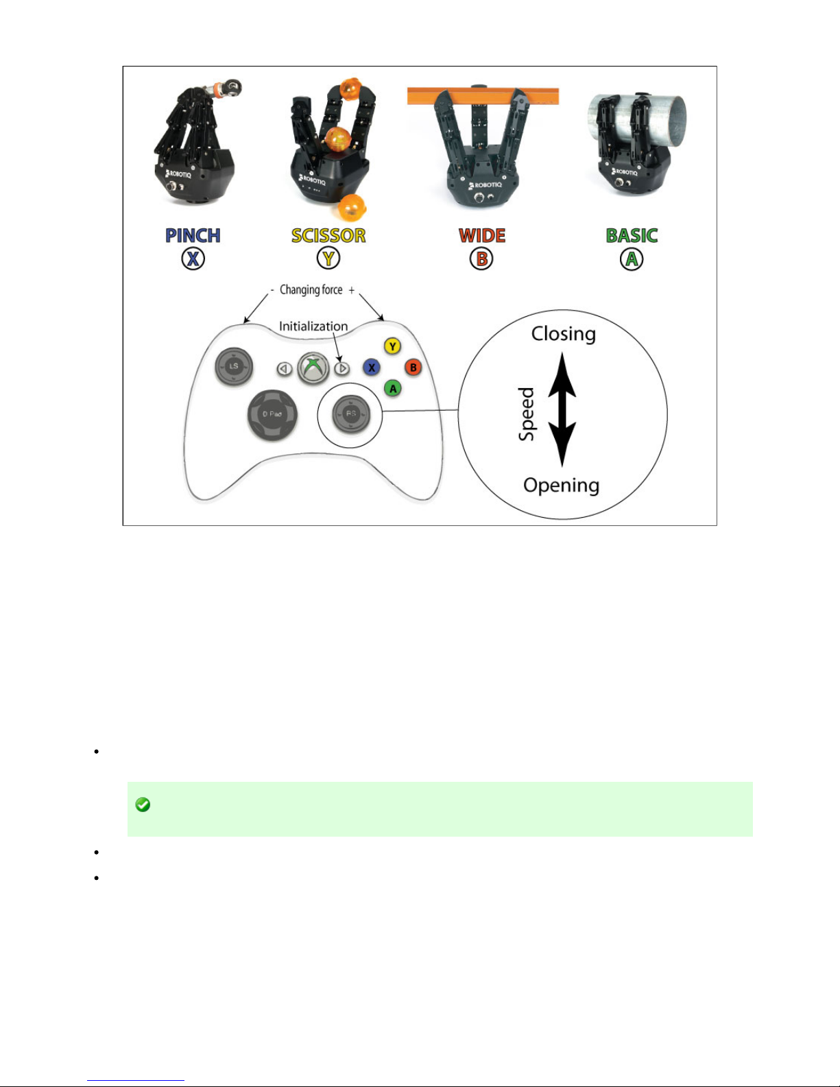
Xbox Joystick control allows control of the Gripper using a remote Xbox controller (see Figure 5.5.2.1 for a summary of the available
controls).
Demo Mode command the Gripper to cycle through its operation modes with pauses after every move.
To disable any of the options simply uncheck the corresponding box.
Robotiq inc. © 2011 44
Robotiq Adaptative Gripper, S model Instruction Manual
Figure 5.5.2.1 Xbox Controls for the Adaptive Gripper S model
5.5.3 Operation Mode
You can select the operation mode of your Gripper in the "Operation Mode" section of the Robotiq User Interface. Simply check the corresponding
radio button or click on the corresponding picture to activate any mode.
For a description of the operation modes see the general presentation in section 1.
5.5.4 Control Parameters
The "Control Parameters" section of the UI can customize all the parameters for the Gripper:
Pos. Request slider sets the reach position of the Gripper when the "Go to requested position" button of the Initialization and Gripper
Fault Status sections are filled with a numeric value. The value can be set anywhere between 0 (fully open) and 255 (fully close).
Hint
You can fix the desired position with the slider or the numeric values.
Force slider will control the grasping force limit of the Gripper. The value can be set anywhere between 0 and 255 with 255 being the
maximum strength.
Speed slider will control the closing or opening speed of the Gripper. The value can be set anywhere between 0 and 255 with 255 being
the maximum speed.
Robotiq inc. © 2011 45

Robotiq Adaptative Gripper, S model Instruction Manual
Figure 5.5.4.1 Changing the control parameters of the Gripper
5.5.5 Gripper Feedback
The "Gripper Feedback" section provides you with information concerning the current status of the Adaptive Gripper.
Object Detection: If the Gripper detects a contact with an object when closing, the "Object Detection" display turns yellow on the
corresponding finger. Object detections are displayed independently for each of the three fingers and the scissor axis.
Figure 5.5.5.1 Positive object detection is registered when the object detection dot turns yellow.
Position (numeric): The digital display of "Position" shows the position of the associated finger as designated on a scale of 0 to 255 (see
for details).section 4.6
Position (graphic): The visual display of "Position" shows the real-time position of each finger graphically. Each axis has an associated
color.
Current (graphic): The "Current" graph shows the amount of current going through each motor. Each axis has an associated color.
Robotiq inc. © 2011 46

Robotiq Adaptative Gripper, S model Instruction Manual
Figure 5.5.5.2 Digital and visual displays of the finger positions and electrical current usage.
5.6 Configuration of the Adaptive Gripper
The allows access to the configuration information of the Gripper, it can only be accessed via Modbus RTU. To access the configuration tab
click this tab in the main Robotiq User Interface screen as shown in configuration tab figure 5.3.2.
The configuration tab display depends on the communication protocol option of your Gripper, each communication protocol being displayed in one
of the following sections:
Ethernet/IP section
Modbus TCP section
DeviceNet section
5.6.1 Ethernet IP
If your Gripper has the communication protocol option, you should see the screen shown in figure 5.6.1.1, when a connection isEthernet/IP
established with the Gripper.
Robotiq inc. © 2011 47

Robotiq Adaptative Gripper, S model Instruction Manual
Figure 5.6.1.1: Default screen of the Configuration Tool with Ethernet/IP
The Configuration Tool with Ethernet/IP screen is described below:
Device Identity section shows the factory settings of your Gripper, these settings are fixed.
Ethernet/IP section shows the current address and options of your Gripper. You can change any option by enabling or disabling it and
changing the values indicated in the fields.
IP address is the networking address used for communication with your Gripper. (IPv4 protocol)
Netmask is the networking subnet address used for communication with your Gripper.
Gateway is the gateway address used within your network. By default this option is disabled.
Extras:
BootP option for Bootstrap Protocol, a network protocol used to obtain an IP address from a configuration server. By
default BootP is disabled.
DHCP option for Dynamic Host Configuration Protocol is an automatic configuration protocol used on IP networks. By
default DHCP is enabled.
100Mbits option for the standard speed of Fast Ethernet (100 Mbit/s). By default it is enabled. If disabled the standard
speed goes to 10 Mbit/s.
Full Duplex option allows full duplex communication (simultaneous two way communication); by default the Full Duplex
is enabled. If disabled it goes to half duplex (not simultaneous two way communication).
Auto-Neg option allows the two connected devices to choose common transmission parameters such as speed, duplex
mode, and flow control. The highest performance parameters will be chosen. By default the Auto-Neg is disabled.
Data section shows the current data length used in input and output during communication.
Input Data Length sets the number of bytes allocated to input data communication.
Output Data Length sets the number of bytes allocated to output data communication.
Hint
You should match the Input and Output data length to the robot I/O on which the Gripper is mounted.
The support section buttons :
Help will pop-up the link to Robotiq support, where you can navigate the Adaptive Gripper manual for help or post comments for
help. You can also access the Robotiq User Interface version you are using via the button. About Robotiq User Interface
Quit or the "X" on the top-right corner will leave the program.
The action buttons function in the following manner:
To apply the changes made in the editable section, click on button.Apply
Robotiq inc. © 2011 48

Robotiq Adaptative Gripper, S model Instruction Manual
Figure 5.6.1.2: Applying the changes, this example changed the default IP of the Adaptive Gripper.
To read the current settings of the Gripper, click on the button.Read
To apply the default settings, click on the button and then click on the button.Default Apply
5.6.2 Modbus TCP
If your Gripper has the communication protocol option, you should see the screen shown in figure 5.6.2.1, when the connection isModbus TCP
established with the Gripper.
Robotiq inc. © 2011 49

Robotiq Adaptative Gripper, S model Instruction Manual
Figure 5.6.2.1: Default screen for the Configuration Tool with Modbus TCP
The Configuration Tool with Modbus TCP screen is described below:
Device Identity case shows the factory settings of your Gripper, these are fixed.
Modbus TCP case shows the current address and options of your Gripper, you can change any option by enabling or disabling it or by
changing the values indicated in the fields.
IP address shows the current networking address used for communication with your Gripper.(IPv4 protocol)
The support section buttons :
Help will pop-up the link to Robotiq support, where you can navigate the Adaptive Gripper manual for help or post comments for
help. You can also access the Robotiq User Interface version you are using via the button. About Robotiq User Interface
Quit or the "X" on the top-right corner will leave the program.
The action buttons are used in the following manner:
To apply the changes made in the editable section, click on the button.Apply
Robotiq inc. © 2011 50

Robotiq Adaptative Gripper, S model Instruction Manual
Figure 5.6.2.2: Applying the changes, this example changed the default IP of the Adaptive Gripper.
To read the current settings of the Gripper, click on the button.Read
To apply the default settings, click on the button and then click on the button.Default Apply
5.6.3 DeviceNet
If your Gripper has the communication protocol option, you should see the screen shown in figure 5.6.3.1, when a connection isDeviceNet
established with the Gripper.
Robotiq inc. © 2011 51

Robotiq Adaptative Gripper, S model Instruction Manual
Figure 5.6.3.1: Default screen of the Configuration Tool with DeviceNet
The Configuration Tool with the DeviceNet screen is described below:
Device Identity case shows the factory settings of your Gripper, these are fixed.
DeviceNET section shows the current address and options of your Gripper. You can change any option by enabling or disabling it and by
changing the values indicated in the fields.
MAC ID is the physical address used for communication with the Gripper. Default is set to 11.
Baudrate is the number of pulse/seconds for communications. The default is set to 250 Kbaud, you can adjust this to 125 Kbaud
or 500 Kbaud.
The support section buttons :
Help will pop-up the link to Robotiq support, where you can navigate the manual for help or post comments for help.
Language will change the language of the Configuration Tool interface.
Français will change the Configuration Tool interface to French.
English will change the Configuration Tool interface to English.
Quit or the "X" on the top-right corner will leave the program.
The action buttons are used in the following manner:
To apply the changes made in the editable section, click on the button.Apply
Robotiq inc. © 2011 52

Robotiq Adaptative Gripper, S model Instruction Manual
Figure 5.6.3.2: Applying the changes, this example changed the default IP of the Adaptive Gripper.
To read the current settings of the Gripper, click on the button.Read
To apply the default settings, click on the button and then click on the button.Default Apply
5.7 Menu Options
Connection menu:
Connect using Modbus RTU: Robotiq User Interface will attempt to connect to the Gripper via Modbus RTU.
Connect using Modbus TCP: Robotiq User Interface will attempt to connect to the Gripper via Modbus TCP.
Disconnect: Will disconnect the connection to the Gripper without leaving the program.
Quit: Will disconnect the connection to the Gripper and close the program.
View menu:
Xbox controls: Will pop-up the Xbox Joystick Control diagram.
Input registers: Will pop-up the Input registers tables, you can refer to for detailssection 4.7
Output registers: Will pop-up the Output registers tables, you can refer to for detailssection 4.6
You can close the pop-up of the "view" menu at anytime, the Robotiq User Interface will stay open.
Help menu:
Support: Will link you to Robotiq support services.
About Robotiq User Interface: Will display the Robotiq User Interface version you are using.
Robotiq inc. © 2011 53

Robotiq Adaptative Gripper, S model Instruction Manual
6. Specifications
6.1 Technical dimensions
Figure 6.1.1 – Robotiq Adaptive Gripper model S technical dimensions.
Robotiq inc. © 2011 54
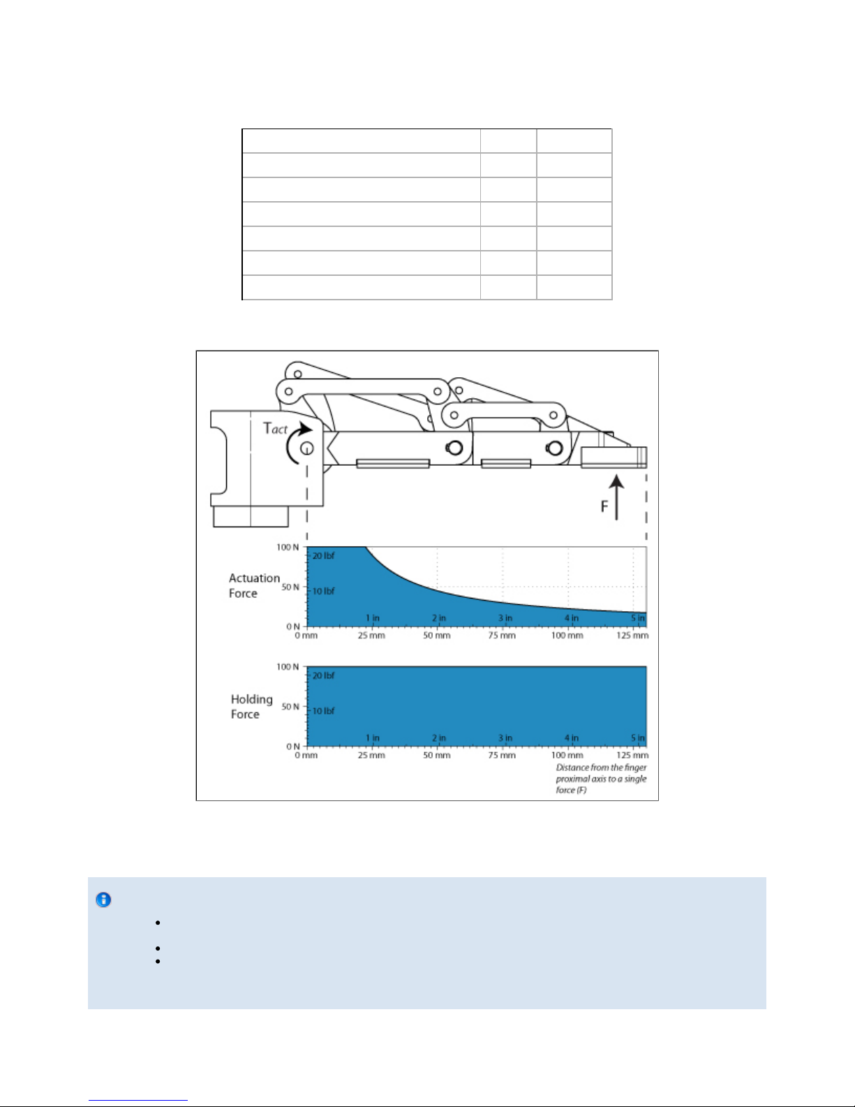
Robotiq Adaptative Gripper, S model Instruction Manual
6.2 Mechanical specifications
Gripper Opening (see )Figure 4.6.1 0-6.7 in [0-169 mm]
Gripper Approximate Weight 5 lbs [2.3 kg]
Recommended Payload (Encompassing Grip) 22 lbs [10 kg]
Recommended Payload (Fingertip Grip) 6.6 lbs [3 kg]
Maximum Grip Force (Fingertip Grip) 10 lbf [40 N]
Maximum Break Away Force 22 lbf [100 N]
Maximum Closing Speed (Fingertip Grip) 4.3in/sec [110mm/sec]
Figure 6.2.1 – Actuation and Holding Forces allowed in a single finger.
Info
The "Actuation Force" is the force that can be applied to an object by the motors of the Gripper while the "Break Away
Force" is the force that the Gripper can sustain
Because the Gripper is self-locking, the Break Away Force is higher than the Actuation Force (see Figure 5.2).
In Pinch Mode, fingers B and C will force against finger A. As finger A is locked, the pinch Actuation Force is the sum of
the Actuation Force from fingers B and C, 20+20 = 40 N.
Robotiq inc. © 2011 55

Robotiq Adaptative Gripper, S model Instruction Manual
The user of the Gripper must always ensure that the result of the forces against the finger is always lower than the maximum Break Away Force.
When doing a fingertip grip, the weight that can be lifted is defined by
Where,
F is the force that is applied to the load by the Gripper. Note that at the fingertips, the maximum force that can be applied is when fingers
B and C force against finger A. In this case, the force can be up to twice the Maximum Actuation Force, so 40N.
Cf is the coefficient of friction between the fingertip pads and the load.
Sf is a safety factor to be determined by the robot integrator.
6.3 Moment of inertia and center of mass
The coordinate system used for calculating the moment of inertia and center of mass of the gripper is shown in . We consider aFigure 6.1.1
configuration where the fingers are fully open in Wide Mode.
Here is the approximate moment of inertia matrix of the gripper:
Here is the approximate position of the center of mass:
6.4 Electrical ratings
Nominal Supply Voltage 24 V
Quiescent Power (minimum power consumption) 4.1 W
Peak Power (at maximum gripping force) 35 W
Maximum RMS Supply Current (supply voltage at 24V) 1.4 A
6.5 Faceplates
6.5.1 Blank faceplate
Robotiq inc. © 2011 56

Robotiq Adaptative Gripper, S model Instruction Manual
Figure 6.5.1.1: Blank faceplate of the Adaptive Gripper S model.
6.5.2 Yaskawa SDA-5D_10D faceplate
Robotiq inc. © 2011 57

Robotiq Adaptative Gripper, S model Instruction Manual
Figure 6.5.2.1: Yaskawa SDA 5D/10D faceplate of the Adaptive Gripper S model.
Robotiq inc. © 2011 58

Robotiq Adaptative Gripper, S model Instruction Manual
7. Warranty
Robotiq warrants this equipment against defects in material and workmanship for a period of one year from the date of reception when utilized as
intended with the specified maintenance. Robotiq also warrants that this equipment will meet applicable specifications under normal use.
During the warranty period, Robotiq will repair or replace any defective product, as well as verify and adjust the product free of charge if the
equipment should need to be repaired or if the original adjustment is erroneous. If the equipment is sent back for verification during the warranty
period and found to meet all published specifications, Robotiq will charge standard verification fees.
The unit is considered defective when at least one of the following conditions occurs:
The Gripper fingers cannot close or open;
The Gripper can't be switched among Operation Modes;
The Gripper feedback necessary for the robot program is not accessible.
Parts that come into contact with the work piece and wearing parts such as the finger and palm pads are not covered by the warranty.
Caution
The warranty will become null and void if the:
Unit has been tampered with, repaired or worked on by unauthorized individuals.
Warranty sticker has been removed.
Screws, other than as explained in this guide, have been removed.
Unit has been opened other than as explained in this guide.
Unit serial number has been altered, erased, or removed.
Unit has been misused, neglected, or damaged by accident.
This warranty is in lieu of all other warranties expressed, implied, or statutory, including, but not limited to, the implied warranties of
merchantability and fitness for a particular purpose. In no event shall Robotiq be liable for special, incidental, or consequential damages.
Robotiq shall not be liable for damages resulting from the use of the product, nor shall be responsible for any failure in the performance of other
items to which the product is connected or the operation of any system of which the product may be a part.
Exclusion
Robotiq reserves the right to make changes in the design or construction of any of its products at any time without incurring obligation to make
any changes whatsoever on units already purchased.
This warranty excludes failure resulting from: improper use or installation, normal wear and tear, accident, abuse, neglect, fire, water, lightning or
other acts of nature, causes external to the product or other factors beyond Robotiq's control.
Robotiq inc. © 2011 59

Robotiq Adaptative Gripper, S model Instruction Manual
8. Contact
www.robotiq.com
Go to Contact Us
Phone
1-888-ROBOTIQ (762-6847)
1-418-800-0045 (outside US and Canada)
Fax
1-418-800-0046
Technical support and Engineering
1-866-508-1997
Sales US
1-812-220-4578
Sales Canada, Europe and Asia
1-418-800-0045
Head office
Robotiq:
966, chemin Olivier
Suite 325
St-Nicolas, Qc
G7A 2N1
Canada
Robotiq inc. © 2011 60
 Loading...