

Page 1
Robotiq FT 300 Force Torque Sensor
Original Notice
© 2018 Robotic Inc.
Instruction Manual
robotiq.com | leanrobotics.org
Page 2

Page 3

1. General Presentation 9
1.1. Main features 10
1.1.1. FT 300 Force Torque Sensor 10
1.1.2. Force Copilot 12
2. Safety 13
2.1. Warning 14
2.2. Intended Use 15
3. Installation 16
3.1. Scope of Delivery 16
3.1.1. Options 16
3.2. Environmental and Operating Conditions 17
3
3.3. Mechanical Connections 17
3.4. Power Supply Specifications 19
3.5. Wiring 20
3.5.1. Wiring with USB to RS485 Converter 21
3.5.2. Wiring with RS232 to RS485 Converter 22
3.6. Installation for Universal Robots 23
3.6.1. Force Copilot URCap Package 24
Installation 24
Calibration Procedure 28
Calibration Procedure with Universal Robots 29
Calibration Procedure for the Visual Demo Software (PC) 33
Payload/CoG 34
ActiveDrive Toolbar Installation 35
Firmware upgrade 36
Uninstalling the URCap Package 37
License Agreement 38
3.6.2. UR Package without URCaps 42
Driver Package Installation 42
Calibration 42
Testing the software package 43
Removing the Package 43
FT300 Force Torque Sensor - Instruction Manual
Page 4

4
3.7. Status LED 44
4. Software 45
4.1. Control with Universal Robots 46
4.1.1. ActiveDrive Toolbar 47
Overview 47
Toolbar collapsed 47
Toolbar expanded 47
ActiveDrive modes expanded 47
Features 48
Error Messages Overview 50
4.1.2. Using the force and torque values 52
4.1.3. Path Recording 54
Overview 55
Features* 57
4.1.4. Insertion nodes 58
Child nodes 59
Features (Spiral) 60
Features (Rotational) 61
Features (Linear) 62
4.1.5. Find Surface node 63
4.1.6. Using the Force Torque Sensor's Data in Force Nodes 66
4.1.7. Force ControlNode 66
Overview 66
Features 68
Reference frame 68
Parameters 69
Test 72
4.1.8. Multipoint Path Node 73
How to set up a Multipoint Path 74
Step 1 74
Step 2 75
4.2. Development Package 77
4.2.1. Distribution License 77
FT300 Force Torque Sensor - Instruction Manual
Page 5

4.2.2. Linux 79
Package Files – Description 79
Procedure to Compile and Test the Provided Source Code 79
Adapt to a User Application 80
4.2.3. Windows 81
Package Files – Description 81
Procedure to Compile and Test the Provided Source Code 81
Adapt to a User Application 82
4.3. Visual Demo Software 83
4.3.1. Software Package Installation 83
4.4. Serial Communication 85
4.4.1. Modbus RTU 85
Connection Setup 86
5
Read Holding Register (FC03) 88
4.4.2. Data Stream 89
Preset Multiple Registers (FC16) 89
5. Specifications 91
5.1. Technical Dimensions 91
5.1.1. Tool Side Bolt Pattern 92
5.2. Mechanical Specifications 93
5.2.1. Moment of Inertia and Center of Mass 94
5.2.2. Overload Capacity 95
5.3. Signal Specifications 96
5.4. Electrical Ratings 98
5.5. Couplings 99
5.5.1. Blank Coupling 100
6. Maintenance 101
6.1. Maintenance Intervals 101
7. Spare Parts, Kits and Accessories 102
8. Troubleshooting 103
8.1. General troubleshooting 103
8.1.1. An offset has appeared in the Sensor data 103
FT300 Force Torque Sensor - Instruction Manual
Page 6

6
8.1.2. Procedure to determine if the Sensor is functional 103
8.2. Troubleshooting on Universal Robots 104
8.2.1. ActiveDrive Toolbar troubleshooting – Error messages overview 104
8.2.2. Monitoring the Sensor state 105
8.3. Troubleshooting on other platforms 107
8.3.1. USB converter detected as a mouse by Windows 107
8.3.2. Data frequency under 100 Hz in Windows 107
8.3.3. In Linux, the serial port cannot be opened 107
9. Warranty 109
9.1. Exclusions 110
10. Contact 111
Appendix A – Translation of Original EC Declaration of Incorporation 113
Appendix B – Applied Standards 114
FT300 Force Torque Sensor - Instruction Manual
Page 7

Revisions
Robotiq may modify this product without notice, when necessary, due to product improvements, modifications or changes in
specifications. If such modification is made, the manual will also be revised, see revision information. See the latest version of this
manual online at: support.robotiq.com.
Revision 2018/10/09
Major update:all reference to the software compatible with UR(URCap)have been renamed Force Copilot
Updated Sofware section to include the Multipoint Path node and rename the FTMode node to Force Control node
Revision 2018/06/18
Updated Software (subsections 4.1.2 and 4.1.5) to include Robotiq FTMode node and corresponding script functions
Revision 2018/03/26
Removed all references to FT 150 Force Torque Sensor
Revision 2018/02/13
Removed reference to ROSpackage (section 4.3)
7
Revision 2017/12/11
Updated control with Universal Robots (section 4.1 and subsections)
Revision 2017/10/30
Updated mechanical specifications (section 5.2)
Updated signal specifications (section 5.3)
Revision 2016/11/18
Updated FT 150 signal specifications (section 5.3)
Updated installation for Universal Robots (section 3.8 and sub sections)
Updated Control with Universal Robots (section 4.1 and sub sections)
Revision 2016/04/26
Update for ActiveDrive toolbar, added calibration instructions
Revision 2016/01/18
Update for FT 300
Revision 2014/09/08
Official release
FT300 Force Torque Sensor - Instruction Manual
Page 8

8
Copyright
© 2016, 2018 Robotiq Inc. All rights reserved.
This manual and the product it describes are protected by the Copyright Act of Canada, by laws of other countries, and by
international treaties, and therefore may not be reproduced in whole or in part, whether for sale or not, without prior written consent
from Robotiq. Under copyright law, copying includes translation into another language or format.
Information provided by Robotiq in this document is believed to be accurate and reliable. However, no responsibility is assumed
by Robotiq for its use. There may be some differences between the manual and the product if the product has been modified after
the edition date.
The information contained in this document is subject to change without notice.
FT300 Force Torque Sensor - Instruction Manual
Page 9
1. General Presentation
The terms ''Sensor'', ''Robotiq Sensor'', ''Force Sensor'', ''Torque Sensor'', ''FT300 Force Torque Sensor'' used in the following
manual refer to the Robotiq Force Torque Sensor FT 300 unless specified. The Robotiq FT300 Force Torque Sensor is a robotic
peripheral designed for force and torque data acquisition.
The term "Force Copilot" used in the following manual refer to the Robotiq Force Copilot unless otherwise specified. The Robotiq
Force Copilot is a software package designed for using the force and torque values read by a force torque sensor in the framework
of robotic applications. The software interface provides force and torque feedback that can be used for robot hand guiding, force
control processes, assembly tasks, product testing,etc.
Info
The following manual uses the metric system, unless specified, all dimensions are in millimeters.
Info
The following section presents the key features of the Sensor and must not be considered as being related to Sensor
operation, each feature is detailed in the appropriate section of the manual. Safety guidelines must be read and
understood before any operation is attempted with theSensor.
9
Fig. 1.1: General presentation of the Robotiq Force Torque Sensors with main features.
FT300 Force Torque Sensor - Instruction Manual
Page 10
10
1.1. Main features
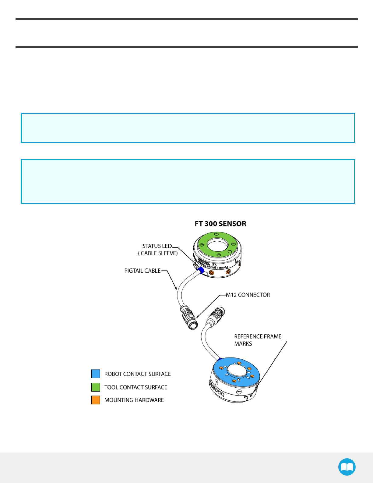
1.1.1. FT 300 Force Torque Sensor
l The end-of-arm tool contact surface (in green) is the only point of contact allowed between the Sensor and the tool to ensure cor-
rect force and torquefeedback.
l The robot contact surface (in blue) is the only contact point allowed between the Sensor and the robot for fastening the sensor to
the robot. Note that the inside ring must not touch the robot.
Info
Details on the bolt pattern and indexing pin for the tool side and the robot side can be found in the Specifications
section.
l The screw positioning for the coupling and the robot mountings are shown in orange. See the Spare Parts section for a list of
available Couplings.
l M12 connector (pigtail or mounted) allows for both power and data transfer for the Sensor.
l Status LED provides visual information on the status of the Sensor, see Section 3.7 for details.
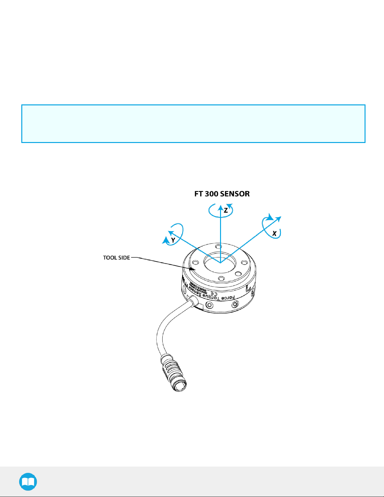
Fig. 1.2: FT300 Force Torque Sensor force and torque diagrams.
FT300 Force Torque Sensor - Instruction Manual
Page 11
The figure above represents the various force and torques that the FT300 Force Torque Sensor can measure. Reference frame is
centered on the Sensor as shown above and visual inscriptions are also represented on it.
l The Z axis passes through the center of the depression with positive direction in the tool direction.
l The X axis traces a symmetric line centered on the connector;the positive direction points the opposite way away from the con-
nector.
l The Y axis uses the right hand thumb rule according to X-Z.
11
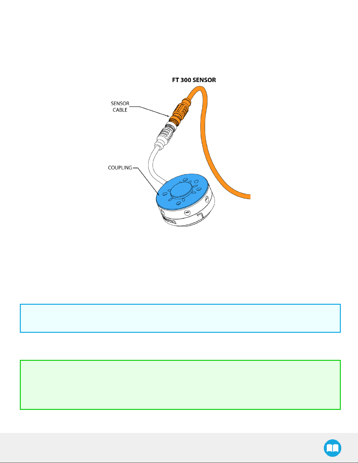
Fig. 1.3: FT300 Force Torque Sensor options.
The figure above represents various options available. They can be found in the Spare Parts, Kits and Accessories section.
l Couplings are meant to install the FT300 Force Torque Sensor on various robot models, see available models.
l Sensor Cable is used for power and communications with the FT300 Force Torque Sensor and is available in different lengths.
l Mechanical Protector is meant to protect the cable connector from collisions that can occur when operating the robot (especially
useful when in teach mode).
l Tool Plate is not shown, but might be required when certain end-of-arm tools are mounted on the FT300 Force Torque Sensor.
Info
Please refer to the Installation section for details on the installation of various options.
Several software packages are provided and detailed in the Software section of this manual.
Tip
It is important to understand that the FT300 Force Torque Sensor can be used either as a Modbus RTU slave or as a
streaming device. When use as a slave unit you will send status requests (read function) to get the force & moment
values, while when in data stream mode the Sensor will continuously stream data without responding to a master
request.Please refer to the Serial Communication section for details.
FT300 Force Torque Sensor - Instruction Manual
Page 12

12
1.1.2. Force Copilot
Force Copilot is the Robotiq software product that unlocks force control features and functionalities.
The Force Copilot software is used for the implementation of a force torque sensor's operational commands in a user interface.
FT300 Force Torque Sensor - Instruction Manual
Page 13

2. Safety
Warning
The operator must have read and understood all the instructions in this manual before handling the Robotiq Force
Torque Sensor and using Force Copilot.
Info
The term "operator" refers to anyone responsible for:
Any of the following operations with the FT300 and the associated robot or tools:
l Installation
l Control
13
l Maintenance
l Inspection
l Decommissioning
Any of the following usage of Force Copilot and the associated operational commands:
l Installation
l Control
l Calibration
l Programming
This documentation explains the various components of the Force Torque Sensor, as well as general operations regarding the
whole life-cycle of the product from installation to operation and decommissioning.
The drawings and photos in this documentation are representative examples and differences may exist between them and the
delivered product.
FT300 Force Torque Sensor - Instruction Manual
Page 14

14
2.1. Warning
Info
Any use of Force Copilot and/or the Force Torque Sensor in noncompliance of these warnings is inappropriate and may
cause injury or damage.
Warning
A force torque sensor used in human-robot collaboration must not be considered a complete safety measure, additional
dedicated safety device(s) must be considered. Sensor failure can occur and result in danger for workers or machinery.
See local or international safety measure for human-robot collaboration.
Warning
l The Sensor needs to be properly secured before operating the robot.
l Do not install or operate a Sensor that is damaged or lacking parts.
l Never supply the Sensor with an alternative current source.
l Make sure all cord sets are always secured at both ends, at the Sensor and at the robot.
l Always meet the recommended keying for electrical connections.
l Make sure no one is in the robot and/or Sensor path before initializing the robot's routine.
l Always meet the Sensor payload specifications.
l All local safety measures and/or laws on robot operation must be applied to the Sensor.
l Any use of the Sensor in noncompliance with these warnings is inappropriate and may cause injury or damage.
FT300 Force Torque Sensor - Instruction Manual
Page 15

2.2. Intended Use
The Sensor is designed for data acquisition (force and torque sensing) for an end-of-arm tool on a robot.
The Sensor is intended for installation on a robot or other automated machinery or equipment.
The software is used for the implementation of a force torque sensor's operational commands in a user interface.
Info
Always comply with local and/or national laws, regulations and directives on automation safety and general machine
safety.
The unit may be used only within the range of its technical specifications. Any other use of the product is deemed improper and
unintended use. Robotiq will not be liable for any damages resulting from any improper or unintended use.
15
FT300 Force Torque Sensor - Instruction Manual
Page 16

3. Installation
Warning
Be sure to read and understand the safety instructions related to the Robotiq Force Torque Sensor prior to installation.
3.1. Scope of Delivery
Standard delivery for an FT Sensor kit:
FTS-300-KIT-001
Robotiq Force Torque Sensor FT 300 unit
1 m pigtail cable (CBL-COM-2068-01)
10 m Robotiq Device Cable (CBL-COM-2065-10-HF)
16
USB Signal Converter (ACC-ADT-USB-RS485)
3.1.1. Options
l Couplings
Info
Coupling is mandatory for the FT 300.
l Adapter plates
l Tool plates
l Different cable lengths
Info
The following are not included in delivery unless specified in the purchase:
l Options such as couplings and adapters for mounting on divers industrial robots.
l Hardware required for options; accessories or fixtures for the FT Sensor unless specified.
l Power supply units, power supply wiring or fuses.
Please refer to the Spare Parts, Kits and Accessories section for a list of available parts.
FT300 Force Torque Sensor - Instruction Manual
Page 17

17
3.2. Environmental and Operating Conditions
The FT300 Force Torque Sensor is designed for industrial applications. Always respect the following specified storage, transport
and operating environmentalconditions:
CONDITION VALUE
Minimum storage/transit
temperature
Maximum storage/transit
temperature
-25°C
70°C
Minimum operating temperature 15°C
Maximum operating temperature 35°C
Humidity (non-condensing) 20-80% RH
Vibration (storage / transit) 5G
Vibration (operating) 2G
l Free from dust, soot or water
l Free from corrosive liquids or gases
Other
l Free from explosive liquids or gases
l Free from powerful
electromagneticinterference
3.3. Mechanical Connections
You must use a coupling to attach the Sensor to a robot. Be sure to use the coupling related to your robot model. Our couplings
are listed according to ISO 9409-1 and this covers most bolt patterns. If there is no coupling for your robot, you can modify a blank
coupling or Robotiq can create a custom version for you. Some couplings may require an additional adapter plate. To create your
own coupling or adapter plate you can refer to the Technical Dimensions section. To see available couplings and adapter plates
and for details, refer to the Spare Parts, Kits and Accessories section.
Info
The FT 300 coupling is mandatory, you can customize yours from a blank provided by Robotiq.
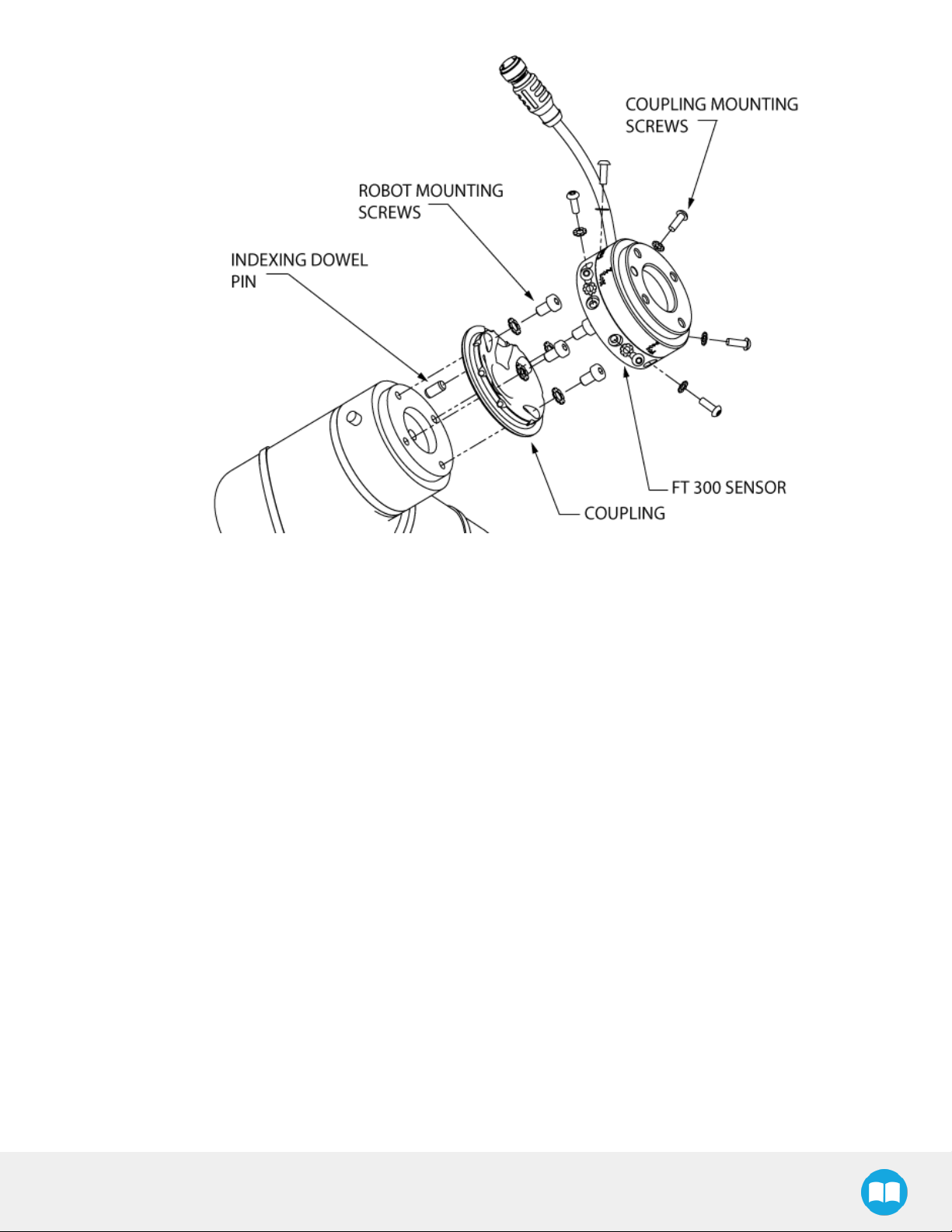
Here are the steps to follow for the installation of the Sensor (see figure below). Note that all screws must be locked in place using
medium strength threadlocker, such as Loctite 248 or a similar product.
1. Align the indexing dowel pin between the coupling and the robot (usually press fitted to the robot).
2. Screw the coupling to the robot with the robot mounting screws (with lock washers if provided) and threadlocker.
3. Align the Sensor indexing dowel pins (prefixed to the Sensor) to the coupling.
4. Screw the Sensor to the coupling using the coupling mounting screws (with lock washers if provided) and threadlocker.
FT300 Force Torque Sensor - Instruction Manual
Page 18
18
Fig. 3.1: Attaching the FT 300 sensor to a robot arm using the mandatory coupling.
FT300 Force Torque Sensor - Instruction Manual
Page 19

19
3.4. Power Supply Specifications
The Sensor needs to be supplied by a DC voltage source. This power supply is not included with the Sensor.
POWER SUPPLY SPECIFICATIONS VALUE
Output voltage 5 to 24 V DC
Max power consumption 2 W
Overcurrent 1 A Fuse (Phoenix #0916604 (UT6-TMC M 1A))
Overvoltage protection
Info
Robotiq recommends the use of the following power supply:
TDK-Lambda DPP Series, 15W Single Output DIN Rail Mount Power Supply, DPP15-24
Warning
Maximum output voltage tolerance is 10%, exceeding this
limit, 26.4 V DC could damage the Sensor.
FT300 Force Torque Sensor - Instruction Manual
Page 20
3.5. Wiring
Power and communications are established with the FT300 Force Torque Sensor via a single device cable. The FT 300 has a pigtail
cable.
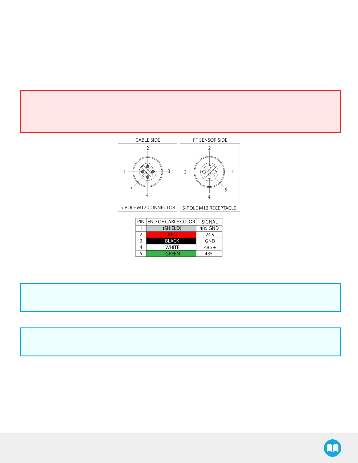
The figure below represents the FT300 Force Torque Sensor receptacle (Sensor side) and connector (cable side) with associated
pinout. The M12 - 5 pin A-coded connector is used in accordance with IEC 61076-2-101.
Warning
Use proper cabling management. Be sure to have enough forgiveness in the cabling to allow movement of the Gripper
along all axes without pulling out the connectors. Always protect the controller side of the cable connection with a strain
relief cable clamp.
20
Fig. 3.2: Pinout of the Robotiq Force Torque Sensor FT 300 and color code for the respective cable type.
Info
Power pins 2 & 3 are connected to the specified power supply.
Info
RS-485 signal pins 1, 4 & 5 are connected directly, to a RS-485 / USB converter or to a RS-485 / RS-232 converter.
FT300 Force Torque Sensor - Instruction Manual
Page 21
21
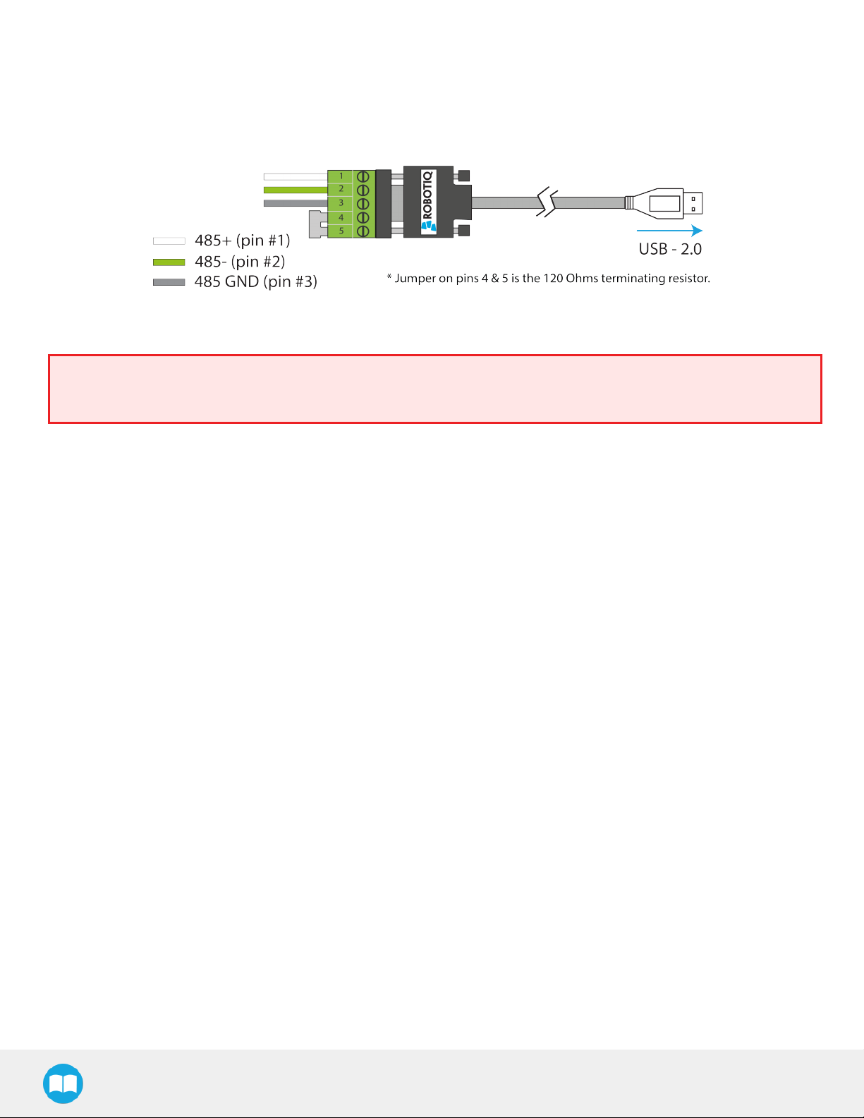
3.5.1. Wiring with USB to RS485 Converter
When using a RS485 to USB converter (refer to the Spare Parts, Kits and Accessories section), the wiring must respect the figure
below and subsequent directions. GND / 0V is wired to Sensor pin #1 as stated in the Wiring section.
The converter will provide you with a standard USB 2.0 male A connector.
Fig. 3.3: Wiring diagram for the RS485 to USB converter
Warning
Power is not delivered via the USB, do not plug 24V into the USB.
FT300 Force Torque Sensor - Instruction Manual
Page 22
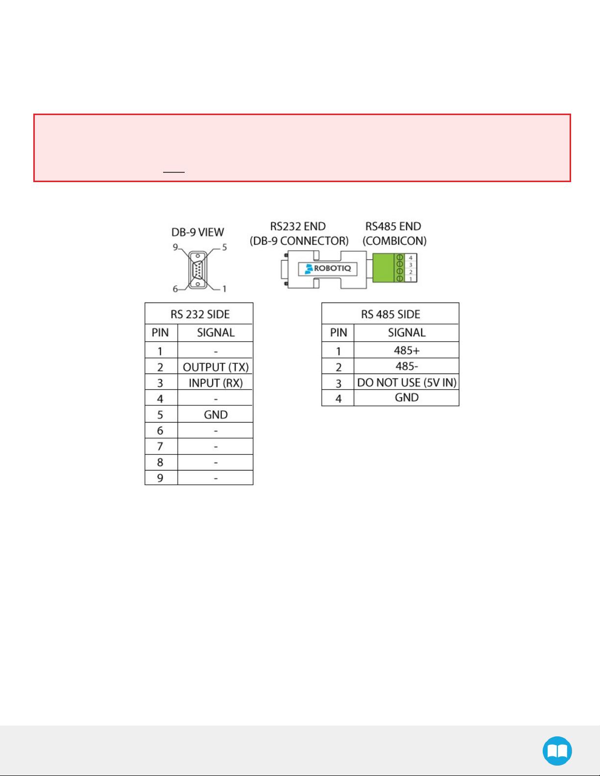
3.5.2. Wiring with RS232 to RS485 Converter
When using a RS232 to RS485 converter (refer to the Spare Parts, Kits and Accessories section), the wiring must respect the figure
below.
Warning
Do not wire converter pin #3 (5V) on the RS485.
The 24V power supply is NOT supplied via the converter.
The converted side will provide you with a standard DB - 9 female connector with signaling as shown in the figure below.
22
Fig. 3.4: Wiring diagram for RS232 to RS485 converter.
FT300 Force Torque Sensor - Instruction Manual
Page 23
23
3.6. Installation for Universal Robots
The table below shows which Robotiq software to use with your version of Universal Robots’ controller. If you are using a CB3 or
CB3.1 controller, it is recommended to use the Force Copilot URCaps Package.
Robotiq Software Universal Robots' controller version
CB1 CB2 CB3 CB3.1
Legacy Driver Package (DFU-1.1.15)
Incompatible
Compatible Compatible Compatible
(includes Gripper toolbar)
ActiveDrive Toolbar (ADU-1.0.1)
FT300 Force Torque Sensor URCap Package
up to 1.1.1 (includes ActiveDrive toolbar)
Force Copilot URCap Package (includes
ActiveDrive toolbar)
Incompatible
Compatible Compatible Compatible
Incompatible Incompatible
Incompatible Incompatible
Compatible Compatible
Incompatible
Compatible
Refer to the appropriate section depending on your controller version:
l The Force Copilot URCap Package section covers the installation of the Force Copilot URCap Package.
l The UR Package without URCaps section goes through the software installation procedures when not using URCaps.
Info
The robot's PolyScope version must be 3.5 and higher in order to install and use the URCap.
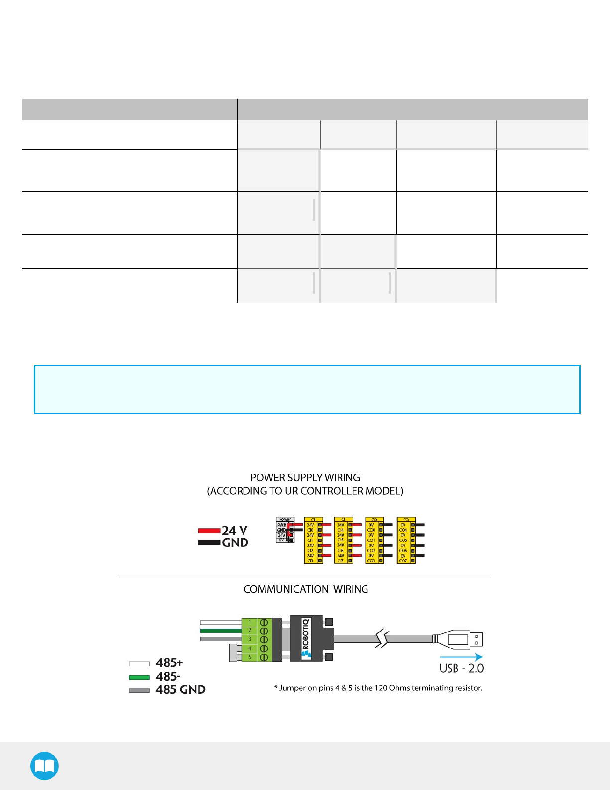
Prior to any software installation, connect the white, green and bare wires to the Robotiq RS-485 signal converter (ACC-ADTRS485-USB) as shown in the figure below. Also connect the red (24V) and black (0V) wires in the controller according to the figure
below.
Fig. 3.5: Force Torque Sensor wiring to Universal Robots’ controller.
FT300 Force Torque Sensor - Instruction Manual
Page 24
Info
Prior to use over Universal Robots, adjust the payload and the center of gravity from the Installation tab (refer to the
Moment of Inertia and Center of Mass section).
3.6.1. Force Copilot URCap Package
Info
The robot's PolyScope version must be 3.5 and higher in order to install and use the URCap.
Installation
Follow this procedure to install the Force Copilot URCap Package.
24
l Browse to support.robotiq.com
l Select Force Copilot
l Download UCS-X.X.X.urcap
l Decompress the file on the USB license dongle
l Insert the USBlicense dongle in the robot teach pendant,
robot controller, or USBhub connected to the robot controller
Caution
Make sure that the license dongle stays
connected to the robot.
l Make sure that your PolyScope version is up-to-date and
that your Universal Robots controller is compatible with
the Force Copilot URCap package. Refer to the Control
with Universal Robots section for the UR controller compatibility.
l Go to support.robotiq.com and click on the product page
of the FT300 Sensor.
l Download the Robotiq_Force_Copilot-X.X.X.urcap file on
a blank USB stick.
l Insert the USB stick in the UR teach pendant or controller.
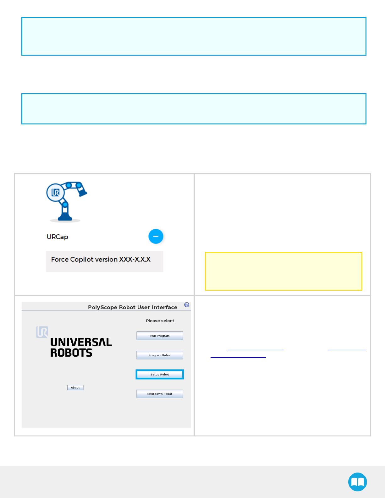
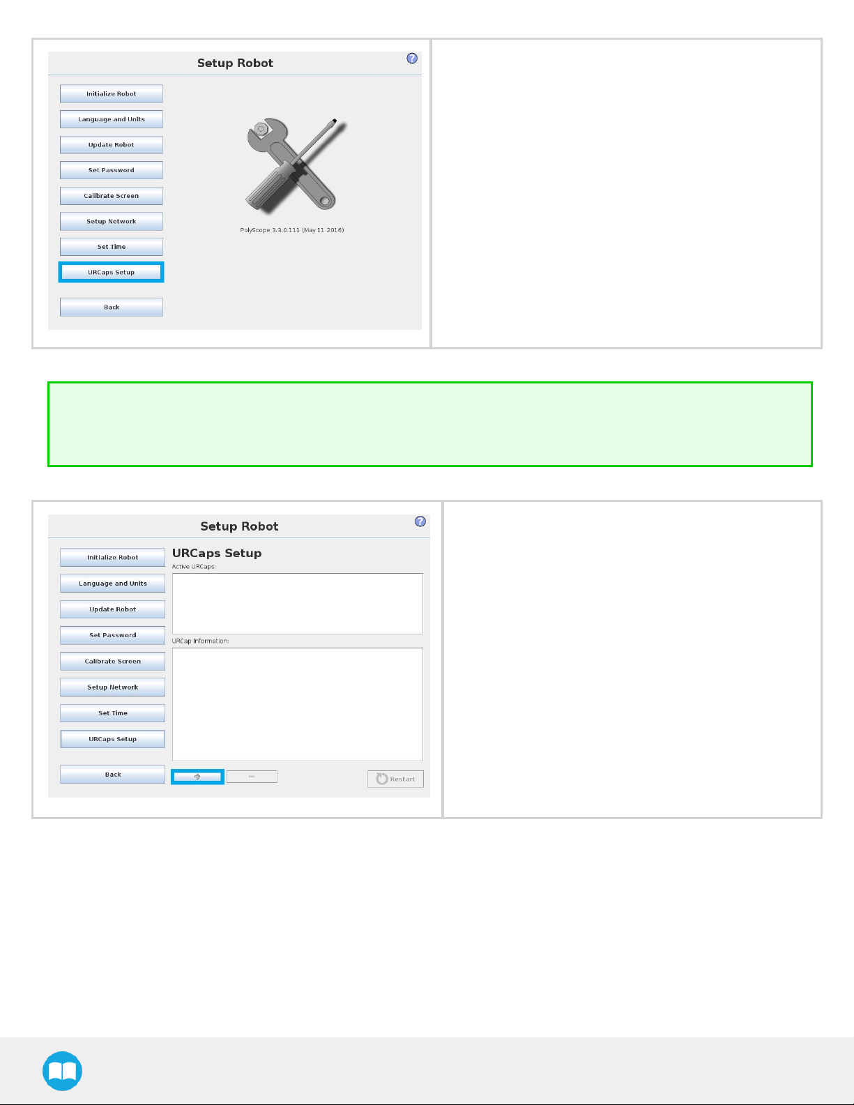
l Go to Setup Robot.
l Tap URCaps Setup.
FT300 Force Torque Sensor - Instruction Manual
Page 25
25
Tip
Go to the PolyScope home page and tap the About button. A window containing the Universal Robots software version
will pop up.
l Tap the plus button (+) to add the Sensor’s URCaps
package.
l Open Robotiq_Force_Copilot-X.X.X.urcap.
FT300 Force Torque Sensor - Instruction Manual
Page 26
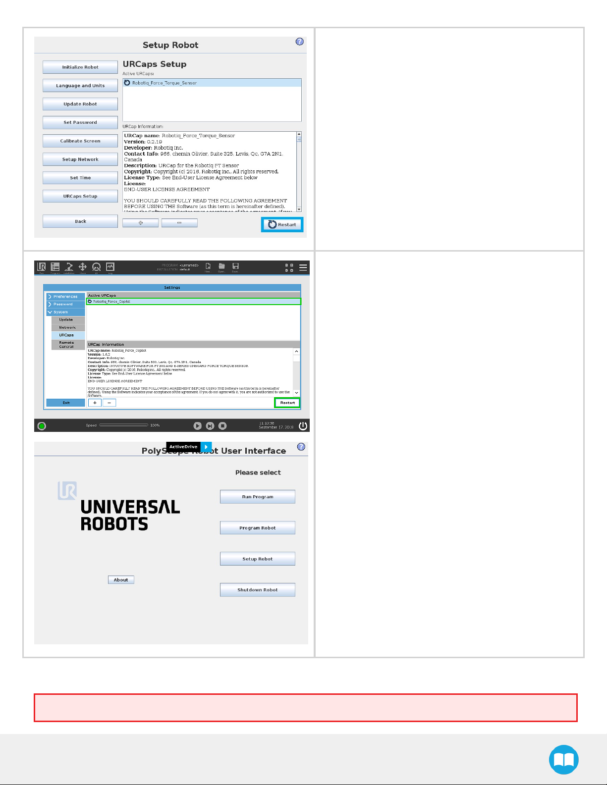
l Restart PolyScope to complete the URCap install-
ation.By doing so, you accept the License Agreement
that is detailed in the URCap Information text box (see
below for the LicenseAgreement).
l When PolyScope reopens, the ActiveDrive toolbar will
appear on thescreen.
26
If the Force Torque Sensor is mounted on the robot for the first time, the calibration must be performed. Refer to the Calibration
Procedure with Universal Robots section for the calibration procedure.
Warning
FT300 Force Torque Sensor - Instruction Manual
Page 27

27
The sensor must be recalibrated after each uninstall / install on the robot. Mounting screws will induce internal stress that
needs to be compensated for. Not doing so will significantly affect the sensor signal.
FT300 Force Torque Sensor - Instruction Manual
Page 28

Calibration Procedure
The sensor outputs the force and moment data according to a reference, i.e. a zero value. In order to compensate for any deviation
of this reference, Robotiq provides a feature which allows the sensor to automatically compute and compensate the installation
offset, the weight of the tool and its center ofmass.
Warning
The sensor must be re-calibrated after each uninstall / install on the robot. Mounting screws will induce internal stress
that needs to be compensated for. Not doing so will significantly affect the sensor signal.
The procedure requires moving the robot arm in three configurations for which each orientation of the tool is different. Using an
internal accelerometer, the sensor is then able to associate the measurements corresponding to the tool alone for each orientation.
After the procedure is completed, the sensor will output the force and moment values measured without the effect of the weight of
the tool and the installation offset.
28
FT300 Force Torque Sensor - Instruction Manual
Page 29
29
Calibration Procedure with Universal Robots
Info
You need the Universal Robots software package installed first.Please refer to the Installation for Universal Robots
section for the package download and installation.
1
On the teach pendant, tap the Installation button in the ribbon at the top of the screen.
2
Select URCaps in the navigation pane on the left of the screen.
3
Tap the Force Copilot button.
4
Select the Calibration tab
1
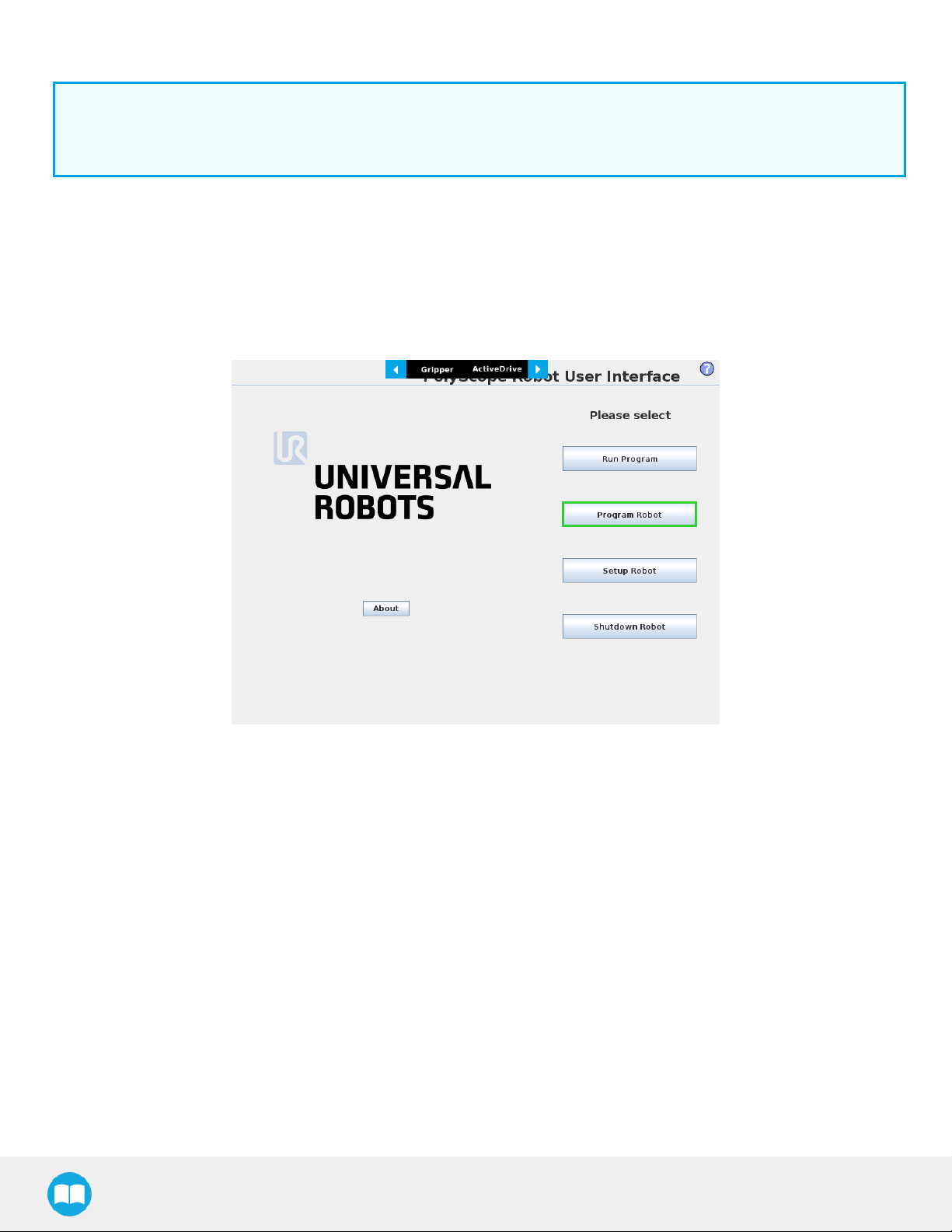
From the PolyScope home page, tap Program Robot.
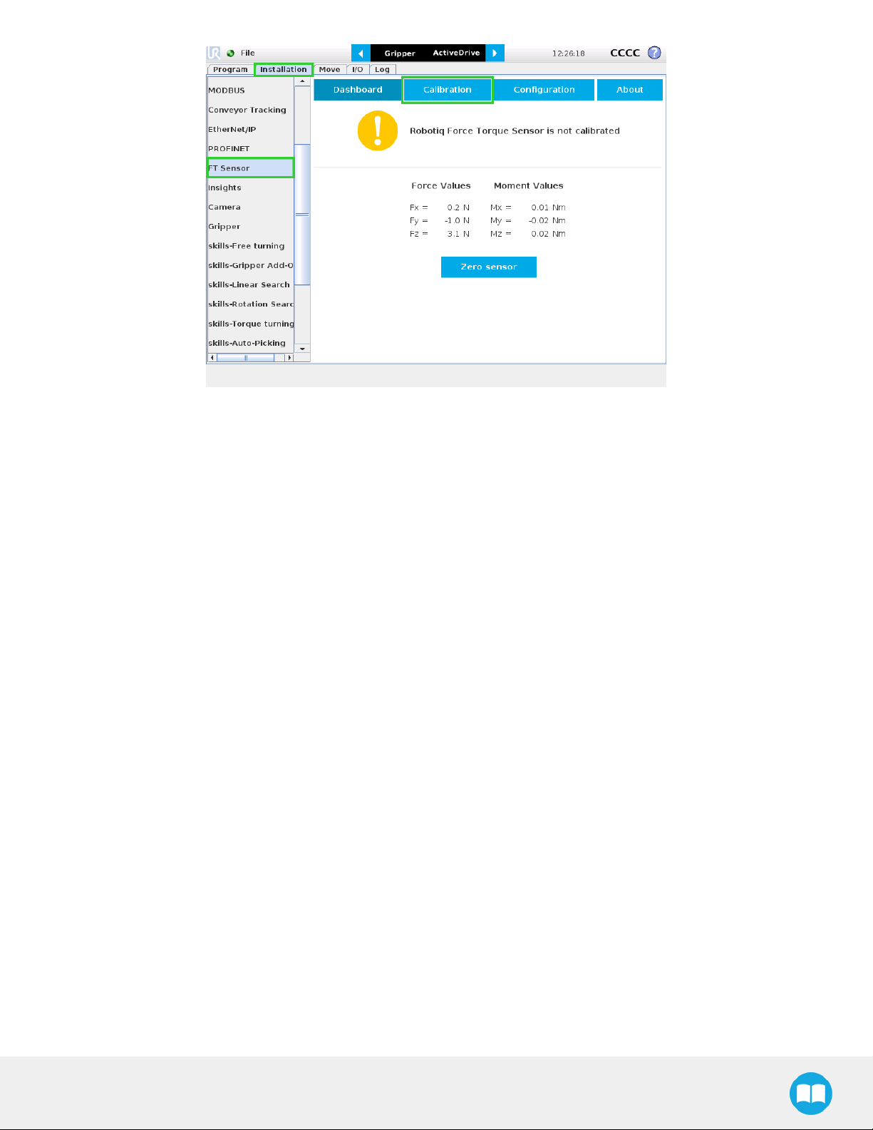
2
Go to the Installation tab and tap FTSensor in the left pane. The FTSensor's Dashboard will be displayed. Tap the Calibration tab.
FT300 Force Torque Sensor - Instruction Manual
Page 30
30
FT300 Force Torque Sensor - Instruction Manual
Page 31

31
3
Tap the Start calibration wizard button to perform the calibration of the FTSensor. Make sure there are no external forces
applied to the Sensor while performing the calibration.
4
Step 1 consists in moving the robot arm so that the FTSensor's Xaxis points downward. Tap Continue when the action is
done.
FT300 Force Torque Sensor - Instruction Manual
Page 32

5
Step 2 consists in moving the robot arm so that the FTSensor's Yaxis points downward.Tap Continue when the action is
done
32
6
Step 3 consists in moving the robot arm so that the FTSensor's Zaxis points downward. Tap Continue when the action is
done
Info
Recalibration is recommended in the event of an error message displaying the incorrect orientation of the FTSensor
during at least one calibration step.
FT300 Force Torque Sensor - Instruction Manual
Page 33
33
Calibration Procedure for the Visual Demo Software (PC)
Info
You need the Visual Demo Software installed first. Please refer to the Visual Demo Software section for download and
installation.
To calibrate your FT Sensor:
1
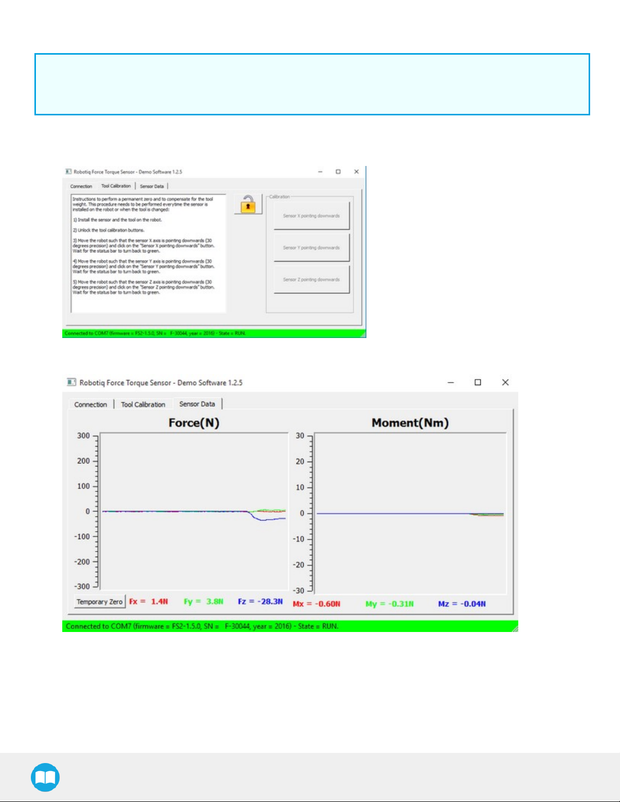
Go to the "Tool Calibration" tab and follow the instructions.
2
Once completed, go to the "Sensor Data" tab.
FT300 Force Torque Sensor - Instruction Manual
Page 34

Payload/CoG
The payload and center of gravity values can be accessed through the Calibration menu in the Installation tab, after the calibration
is completed. They include the mass and center of gravity of the Sensor.
Caution
The mass, payload or center of gravity of anything found under the Sensor (i.e. tool changer) will not be taken into
account in the calculation of the payload.
Warning
Make sure to save the installation file after performing the calibration. Saving will record the calibration date and
estimate tool parameters.
34
FT300 Force Torque Sensor - Instruction Manual
Page 35

35
ActiveDrive Toolbar Installation
Tip
Prior to installing the ActiveDrive toolbar, the Sensor Driver package should be installed.
Info
The URCaps package contains the ActiveDrive Toolbar. Therefore, installing the URCap package also installs the
toolbar. If you have installed the URCap, you do not need to install the ActiveDrive Toolbar. This section applies to
Robotiq’s software installation when not using the URCap. If you wish to install the URCap package, refer to the Force
Copilot URCap Package section.
Tip
Make sure your PolyScope version is up-to-date and that your controller is compatible with the driver package for UR
(refer to the Installation for Universal Robots section for controller compatibility). To view your PolyScope version, go to
the home page of the teach pendant and tap the About button. A window containing the Universal Robots software
version will pop up.
Warning
Verify that the Force Torque Sensor is aligned with the robot arm using the dowel pin, or at least make sure the holes are
aligned. This ensures that the Sensor’s axes are aligned with the robot’s and that the ActiveDrive will work correctly.
To install the ActiveDrive toolbar :
1
Visit support.robotiq.com and download the latest ActiveDrive toolbar installer (ADU-X.X.X) in the Documentation Archives
section.
2
Extract the files on a blank USB stick.
3
Connect the USB stick in the Universal Robots’ teach pendant or controller.
4
Installation is automatic. The pendant’s screen will show installation status.
5
Do not remove the USB stick before the installation is completed.
6
Once the installation is completed, the ActiveDrive Toolbar button will appear on the teach pendant’s screen after a short
delay.
Info
To get detailed information on how to use the ActiveDrive Toolbar, refer to the ActiveDrive Toolbar section.
FT300 Force Torque Sensor - Instruction Manual
Page 36

Firmware upgrade
A firmware upgrade might be necessary when updating the Force Copilot URCap. From the PolyScope home page, go to Program
Robot and tap the Installation tab. Select FT Sensor in the left pane and tap the Dashboard button. If an upgrade is needed, the
Upgrade firmware button will display. Tap the button and wait for the upgrade to be completed.
Warning
Do not disconnect the Sensor during firmware upgrade.
l Tap Upgrade firmware
36
Wait while the software is upgraded.
FT300 Force Torque Sensor - Instruction Manual
Page 37

37
Uninstalling the URCap Package
If you wish to uninstall the Force Copilot URCap, follow this procedure:
Go to Setup Robot.
Tap URCaps Setup.
l In the Active URCaps text box, tap the Force Copilot URCap.
l The Force Copilot URCap should be highlighted.
l Tap the minus button (-) to uninstall the URCap.
l Restart PolyScope to complete the uninstallation process.
FT300 Force Torque Sensor - Instruction Manual
Page 38

License Agreement
END-USER LICENSE AGREEMENT
YOU SHOULD CAREFULLY READ THE FOLLOWING AGREEMENT BEFORE USING THE SOFTWARE (as this term is hereinafter
defined). Using the Software indicates your acceptance of the agreement. If you do not agree with it, you are not authorized to use
the Software.
IMPORTANT, READ CAREFULLY: This End-User License Agreement (the “Agreement”) is a legal agreement between you and the
Licensor (as this term is hereinafter defined), the licensor of the Software. This Agreement covers the Software. The Software
includes any “on-line” or electronic documentation and all modifications and upgrades related thereto. By downloading, installing,
or otherwise using the Software, you agree to be bound by the terms of this Agreement. If you do not agree to the terms of this
Agreement, the Licensor cannot and does not license the Software to you. In such event, you must not download, use or install the
Software.
1. Definition.
1.1. “UR” means Universal Robots A/S, a corporation incorporated under the laws of Denmark, having its registered office at
Energivej 25, DK-5260 Odense S, which specializes into the conception, advanced manufacturing and sale of robotic products
(the “UR’s Business”);
1.2. “Software” means any of the Licensor’s software provided to its customers for the purposes mentioned in sub-section 2.2
hereof including their modifications and upgrades and their related materials;
38
1.3. “Licensor” means Robotiq inc., a corporation incorporated under the laws of Quebec, having its registered office at 500-966
chemin Olivier,Lévis, Québec, Canada, G7A 2N1, which specializes into the conception, advanced manufacturing and sale of
robotic products (the “Licensor’s Business”);
1.4. “End-User” means a customer authorized pursuant to this Agreement to install or use the Software with a specific product of
the UR’s Products;
1.5. “Licensor’s Products” means those robotic products developed by the Licensor in the course of the Licensor’s Business;
1.6. “UR’s Products” means those products developed by UR in the course of the UR’s Business;
1.7. “Licensor’s Authorized Representatives” means and includes the Licensor and Licensor’s authorized vendors, resellers,
distributors and licensors;
1.8. “Designated Equipment” means a personal computer that has a functional USB port and an operating system that is an
equivalent or a more recent version of one of the following:
l Windows 7;
l Mac OSX;
l Linux Ubuntu 16.
1.9. “Purchase Agreement” means an agreement between the End-User and the Licensor pursuant to which the End-User
purchased one or more of the Licensor’s Products;
1.10. “Trial Period” means the limited period during which the Software may be installed on the UR’s Product and used without
any charge by the End-User in order to be used without a Licensor’s Product.
2. License and Object of the Agreement.
2.1. License. Subject to the terms and conditions hereof, the Licensor grants to the End-User a personal, temporary, nonexclusive, non-assignable and non-transferable and revocable license to use the Software in accordance with the terms and
conditions hereof.
2.2. Object of the Agreement. The object of this Agreement is the grant of a license for the use of software that enables control
functionalities of UR’s Products devices or Licensor’s Products (the “Purpose”).
FT300 Force Torque Sensor - Instruction Manual
Page 39

39
3. Software and Documentation.
3.1. Download. The Software shall be downloaded from the Licensor’s website or provided to the End-User through a USB flash
drive, according to the instructions set forth in the order summary sent to the End-User by email or by other means of
communication, as decided by the Licensor (the “Order Summary”). The download of the Software shall be made with the EndUser’s Designated Equipment.
3.2. Installation. The installation on the UR’s Product shall be done with a USB flash drive inserted into the UR’s Product. If the
Software was downloaded from the Licensor’s website, it shall be uploaded on a USB flash drive device for the purpose of
installation on the UR’s Product.
3.3. Utilisation. Two scenarios are possible according to the modalities set forth in the Order Summary:
a) The use of the Software is made with a Licensor’s Product. In this case, the End-User may start using the Software upon
completed installation.
b) The use of the Software is made without a Licensor’s product. In this case,a Trial Period is granted to the End-User. At the
end of the Trial Period, which shall be set forth in the Order Summary, the use of the Software requires the software protection
dongle (the “Dongle”). The Dongle will be provided to the End-User for a fee as per section 5 of this Agreement, either by the
Licensor or by a Licensor’s Authorized Representative.
3.4. Documentation. The Licensor may provide, if applicable, all documentation containing the detailed specifications for
operation and use of the Software, which Software shall be used in accordance with such documentation. This documentation, if
applicable, will be provided, wholly or in part, within (i) this Agreement, (ii) the Licensor’s Web site http://robotiq.com/ (iii) the
Licensor’s Products and the Purchase Agreement therewith, or (iv) any other agreement, document, support, whatsoever decided
by the Licensor.
4. Modifications and Upgrades. The Licensor shall be under no obligation to provide any upgrade, modification or patch to the
Software. However, the End-User shall be entitled to receive free of charge the upgrades and patches of the Software provided by
the Licensor if, at such time, the End-User is not in default in respect of any of its obligations contained herein. Modifications that
create new functionalities may be offered to the End-User at a price set by the Licensor at its sole discretion.
Such modifications, upgrades and patches of the Software shall be installed by the End-User itself by consulting the Licensor’s
website http://robotiq.com/ where a link to proceed to such installation will be made available thereof.
5. Fees. The End-User shall pay the Licensor for using the software as per the Order Summary. The fees shall cover upgrades and
patches of the Software provided by the Licensor if, at the time of the upgrade or patch, the End-User is not in default in respect of
any of its obligations contained herein.
New End-Users not using the Licensor’s Products will be entitled to a Trial Period, which shall begin on the date of the first
installation on the UR’s Product and which shall end after the Trial Period as determined in the Order Summary.
6. Maintenance. During the term of this Agreement, the Licensor will maintain the Software in an operable condition and will make
available any corrections and improvements as are generally incorporated in the Software by the Licensor without additional
charge to the End-User.
7. Title to Software. The licensed Software is composed of confidential data and trade secrets and is proprietary to and constitutes
trade secret information and intellectual property of the Licensor. Title and ownership rights to the Software, including the
intellectual property rights related thereto, shall remain with the Licensor. The End-User agrees to maintain the confidential nature
of the source code and libraries.
The license granted herein does not include the right to sublicense to others, and may not be assigned to others, in whole or in
part, without the prior written consent of the Licensor. The End-User may not or allow others to modify or prepare derivative works,
copy (except for normal backups for recovery purposes), reproduce, republish, reverse engineer, upload, post, transmit, or
distribute, in any manner, the Software.
8. Restricted Use. The Software shall be used solely and exclusively by the End-User and its employees for the Purpose mentioned
in sub-section 2.2 hereof. Any other use of the Software, including resell derivative modifications or extensions, is expressly
prohibited.
9. Audit. During the term of this Agreement and for six (6) months after the termination, the Licensor shall have the right, during
normal business hours and upon reasonable advance notice to the End-User, to visit the End-User’s premises for the purpose of
FT300 Force Torque Sensor - Instruction Manual
Page 40

auditing the End-User’s use of the Software to confirm that such use is in accordance with this Agreement or to confirm that the
End-User has ceased the use of the Software after the termination of the Agreement.The costs of such audit shall be borne by the
Licensor unless it determines that the End-User has underpaid it for any twelve-month period by five per cent (5%) or more or that
the use of the Software is not in accordance with the Agreement; in such case, the End-User shall pay the costs of the audit and
such underpayment.
10. Exclusion of Warranty on Software. The End-User expressly acknowledges and agrees that use of the Software is at the EndUser sole risk. The Software is provided “as is”. The Licensor warrants that, during the term of this Agreement and except if
modified by the End-User, the Software will meet in all material respects the specifications provided for in the Licensor’s website.
11. Limitation of liability. To the maximum extent permitted by law, the Licensor and Licensor’s Authorized Representatives shall
not be liable for any indirect, incidental or consequential damages for breach of any express or implied warranty,breach of
contract, negligence, strict liability or any other legal theory related to the Software. Such damages include, but are not limited to,
loss of profits, loss of revenue, loss of data, loss of use of the product or any associated equipment, down time and user’s time,
even if the Licensor has been advised of the possibility of such damages. In any case, the Licensor’s entire liability under any
provision of this agreement shall be limited to the amount actually paid in respect of the Licensor’s products purchased by the enduser pursuant to a purchase agreement.
12. Indemnification. The End-User shall indemnify and hold the Licensor harmless from any liability, loss, claim and from any
judgment, damage and cost (including, without limitation, the costs and fees of a dispute and reasonable legal fees), fine, penalty
and interest whatsoever arising from any defence, dispute, compensation, claim or counterclaim as a result of the use of the
Software by any third party authorized by the End-User.
13. Training, Maintenance and Support. There is no entitlement to training, maintenance and support under this license unless
otherwise specified in the Purchase Agreement or any other written agreement between the End-User and the Licensor. The EndUser may provide the Licensor with details regarding any bug, defect or failure in the Software promptly and with no delay from
such event; the End-User shall comply with the Licensor’s request for information regarding bugs, defects or failures and furnish
him with information, screenshots and try to reproduce such bugs, defects or failures upon Licensor’s demand.
40
14. Expiration and Termination. The Licensor may terminate this Agreement for default by the End-User by sending a ten (10) day
notice to the End-User.
Upon the termination of this Agreement for any reason, the End-User shall promptly uninstall the Software on any UR’s Products
and Licensor’s Products, computer, or server on which it has been installed, deliver to the Licensor all CDs, DVDs, USB flash drives,
and other tangible items and materials embodying the Software, and return to the Licensor all copies thereof or destroy such
copies and warrant in writing that all copies thereof have been destroyed or deleted. In the event of the termination of this
Agreement, all obligations of the parties under this Agreement due for performance on the date of termination shall survive the
termination, and the party terminating shall not be liable to the other party for any damages arising out of the termination.
15. Miscellaneous.
15.1. This Agreement constitutes the entire understanding and agreement between the Licensor and the End-User and replaces
any prior agreement relating to the same subject matter.
15.2. This Agreement shall be governed and construed in accordance with the laws of the province of Quebec and the federal
laws of Canada applicable therein. Any legal action or proceeding between the Licensor and the End-User for any purpose
concerning this Agreement or the parties' obligations hereunder shall be brought exclusively in a court of competent jurisdiction
sitting in the judicial district of Québec, Québec.
15.3. The Licensor’s failure to insist upon or enforce strict performance of any provision of this Agreement shall not be construed
as a waiver of any provision or right. Neither the course of conduct between the parties nor trade practice shall act to modify any
provision of this Agreement.
15.4. The Licensor may assign its rights and duties under this Agreement to any party at any time without notice to the End-User.
The End-User may not assign this Agreement without the prior written consent of the Licensor.
15.5. If any part of this Agreement is null, illegal or non-enforceable, this Agreement shall be interpreted as if this part was never
part of this Agreement.
15.6. The provisions of this Agreement are for the benefit of the Licensor and its officers, directors, employees, agents, licensors
and suppliers. Each of these individuals or entities shall have the right to assert and enforce those provisions directly against the
FT300 Force Torque Sensor - Instruction Manual
Page 41

41
End-User on its own behalf. This Agreement is also for the benefit of, and binds, the End-User and its heirs, successors, legal
representatives and permitted assigns.
15.7. The Licensor hereby confirms that there is no relationship of agency between the Licensor and UR, and that they are
independent contractors.
15.8. Any rights not expressly granted herein are reserved.
15.9. The parties confirm that they have agreed that this Agreement and all related documents be drafted in English only. Les
parties aux présentes confirment qu’elles ont accepté que la présente convention et tous les documents y afférents soient rédigés
en anglais seulement.
FT300 Force Torque Sensor - Instruction Manual
Page 42

3.6.2. UR Package without URCaps
If your Universal Robots controller is not compatible with the URCaps package (refer to the Installation for Universal Robots section
for compatibility), you can install the driver package and ActiveDrive Toolbar separately.
The ActiveDrive Toolbar allows to easily move the robot by hand guiding it. This section applies to Robotiq’s software installation
when not using URCaps.
Info
The driver package and the ActiveDrive toolbar have separate installation processes. The driver package is independant
from the ActiveDrive toolbar, but has to be installed beforehand if you wish to install the ActiveDrive toolbar.
Driver Package Installation
Info
The URCap package contains the driver package. Therefore, installing the URCap package also installs the driver
package. If you have installed the URCap, you do not need to install the driver package. This section applies to
Robotiq’s software installation when not using the URCap. If you wish to install the URCap package, refer to the Force
Copilot URCap Package section.
42
Caution
Make sure your PolyScope version is up-to-date and that your controller is compatible with the driver package for UR
(refer to the Installation for Universal Robots section for controller compatibility). To view your PolyScope version, go to
the home page of the teach pendant and tap the About button. A window containing the Universal Robots software
version will pop up.
To install the driver package, follow this procedure:
1
Download the Robotiq Force Torque Sensor software driver package (DFU-X.X.X) from the Documentation Archives.
2
Extract the content of the .zip file on a blank USB flash drive.
3
Plug the flash drive into the robot controller or teach pendant.
4
Installation is automatic. The pendant screen will show installation status. Do not unplug the flash drive until the operation is
completed.
5
When a green "USB" text is shown, unplug the USB drive.
Calibration
If the Force Torque Sensor is mounted on the robot for the first time, calibration must be performed. Refer to the Calibration
Procedure section for details.
Warning
The Sensor must be calibrated after each uninstall / install on the robot. Mounting screws will induce internal stress that
needs to be compensated for. Not doing so will significantly affect the Sensor signal.
FT300 Force Torque Sensor - Instruction Manual
Page 43

43
Testing the software package
l In PolyScope, load the program test_sensor.urp located in the Sensor folder and execute it. The program will display pop-ups
with the following information: Sensor firmware version, production year and serial number. The force and torque readings for Fx,
Fy, Fz, Mx, My and Mz are displayed in the Variables tab.
Info
To get detailed information on how to program in PolyScope using the Force Torque Sensor signals, refer to the Using
the force and torque values section.
Removing the Package
1
Locate the uninstall.sh file provided in the driver package.
2
Copy the file on a blank USB stick.
3
Rename the file to urmagic_uninstall.sh.
4
Plug the USB stick into the UR controller or teach pendant.
5
Uninstallation is automatic.
FT300 Force Torque Sensor - Instruction Manual
Page 44

3.7. Status LED
A single status LED provides information on both Sensors, detailed information can be found in the tables below, while a
representation of both Sensor status LEDs is shown in the figure below.
On the FT 300 Sensor, the cable sleeve is the LED conductor:
COLOR LED STATE INFORMATION
- off No power
Blue / red on FT 300 Sensor is booting
Red on FT 300 Sensor is functional, no
communication detected
Red blinking FT 300 Sensor fault detected
44
Blue on FT 300 Sensor is functional,
communication established
Fig. 3.6: FT Sensor status LED.
FT300 Force Torque Sensor - Instruction Manual
Page 45

4. Software
The following sub-sections provide instructions for the installation of the Force Copilot software package. This allows you to get
data from a force torque sensor.
l Section 4.1 and subsections refers to the control and programming for Universal Robots.
l Section 4.2 and subsections detail the installation of an open source development package, which can be adapted according to
the users' needs. It currently functions with Windows and Linux.
l Section 4.3 links to ROS.
l Section 4.4 explains the Demo Software
l Section 4.5 will detail the use of serial communication in generic applications
45
FT300 Force Torque Sensor - Instruction Manual
Page 46

46
4.1. Control with Universal Robots
Force Copilot contains many features to program and control the robot’s arm using a sensor’s force and torque readings. The
packageprovides:
l ActiveDrive toolbar;
l Path recording node;
l Zero FTSensor node
l Insertion node
l Find Surface node
l Force Control node
l Multipoint Path node
l Driver package.
FT300 Force Torque Sensor - Instruction Manual
Page 47
4.1.1. ActiveDrive Toolbar
The ActiveDrive Toolbar is automatically installed with the Force Copilot software Package. It enhances the guiding mode on
Universal Robots by allowing the robot to be hand guided smoothly and easily towards a waypoint. The ActiveDrive feature is a
great way to assist the Path recording described in the Path Recording section, by hand guiding the robot while recording a path.
Info
The Force Copilot software Package contains the ActiveDrive Toolbar. Therefore, the toolbar is automatically installed
with the URCap Package.
Info
The ActiveDrive Toolbar can be installed and used without the URCap Package (refer to the UR Package without
URCaps section for information on how to install the toolbar without the URCap).
Warning
Verify that the Force Torque Sensor is aligned with the robot arm using the dowel pin. This ensures that the Sensor’s axes
are aligned with the robot and that the ActiveDrive feature will work correctly.
47
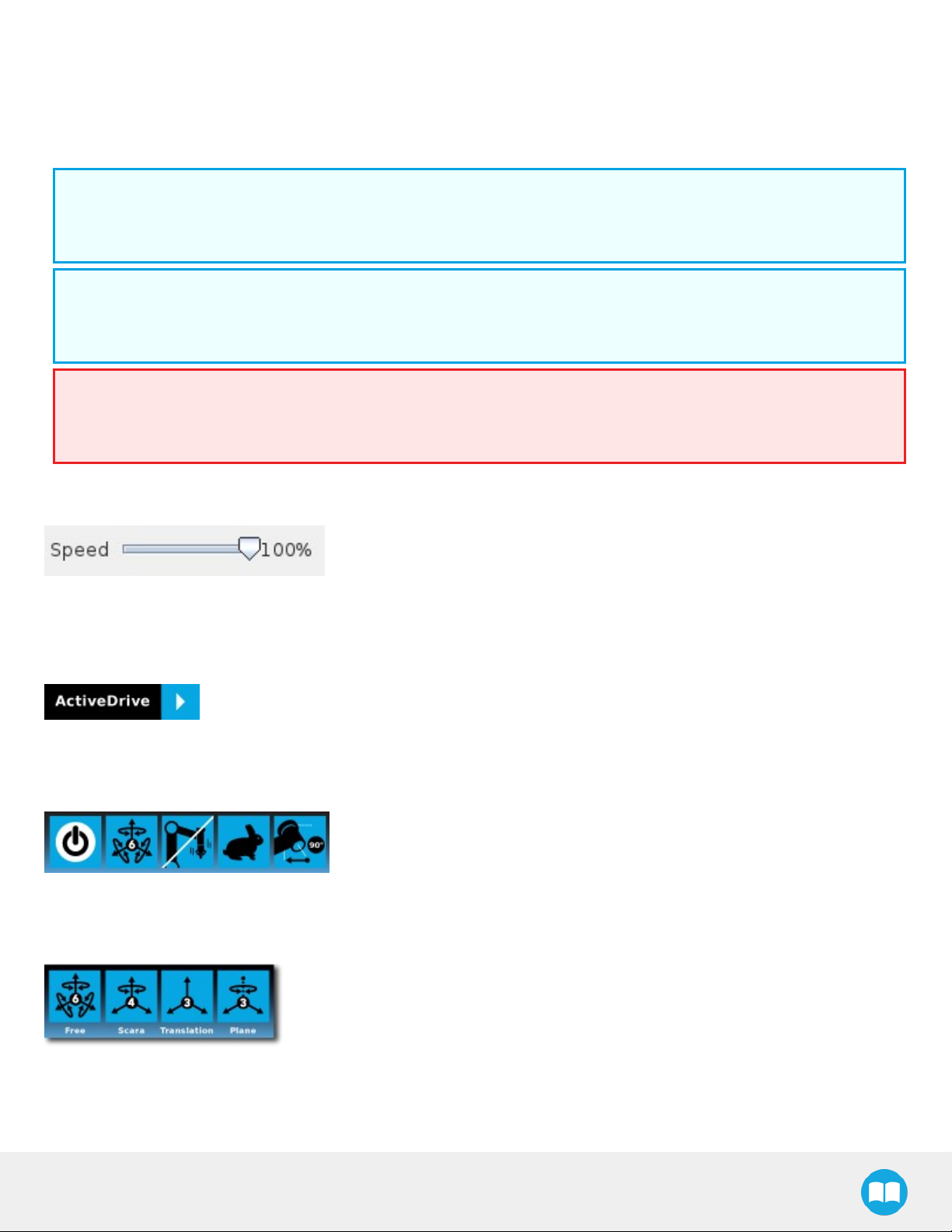
The robot speed set with the Speed slider will affect the speed at which the robot moves in the ActiveDrive mode. Verify and adjust
the speed slider to the desired speed. It has to be greater than 50%.
Overview
Toolbar collapsed
Tap the ActiveDrive button to expand the toolbar.
Toolbar expanded
(Tap the mode selector to expand.)
ActiveDrive modes expanded
FT300 Force Torque Sensor - Instruction Manual
Page 48

48
Features
Primary icon Functionality
name
ActiveDrive Tap to toggle between the expanded and collapsed ActiveDrive Toolbar. When
Start / Stop Tap to start or stop ActiveDrive. ActiveDrive will automatically turn off after 30s of
Modes Shows the current ActiveDrive mode. When tapping the icon, the available modes
Description
grey, the functionality is not available. Tap the button to see why it is not available.
inactivity.
When started, ActiveDrive allows you to move the robot freely by applying forces
on robot’s end-effector. This is different from the Free Drive feature on the robot,
where you can move the robot arm.
will appear and you can change to a different mode. ActiveDrive modes allow you
to restrain the robot to specific movements.
Free Free motion: all translations and rotations are allowed.
Scara SCARA-style motion: all translations and horizontal rotation (twist) are allowed.
Translation Translation motion: only translations are allowed. No rotation of the robot is
possible in this mode.
Plane Plane motion: horizontal translations and horizontal rotations (twist) are allowed (no
vertical motions are allowed).
Drift Control Tap this button to stop the robot from drifting (resets the sensor’s offset).
FT300 Force Torque Sensor - Instruction Manual
Page 49

49
Primary icon Functionality
name
Speed Motion speed control is toggled between fast and slow, allowing precise
Square robot Aligns the tool center point (TCP) orientation with the robot base. Tap and hold this
Description
movement in slow motion.
The force torque sensor will switch to slow speed automatically whenever high
forces are detected, for example, during an impact with an object.
button to automatically move the end-effector to the closest orthogonal orientation
of the base axis system (just try it, you will see!).
FT300 Force Torque Sensor - Instruction Manual
Page 50

50
Error Messages Overview
The ActiveDrive Toolbar will be automatically collapsed and be grayed whenever one of the following situations occurs. In such
cases, by tapping the ActiveDrive button, the following messages will appear:
l Message:
l Solution:
l Starting ActiveDrive while an excessive force is applied to the tool:
l Determine if an external force is applied to the end-effector. If it is the case, tap OK and move the robot away from the
obstacle (with Free Drive or Move tab), or remove any external forces and start ActiveDrive again.
l If no external forces are applied, tap Zero Sensor.
l Message:
l Solution:
l
Force Torque Sensor is detected: Check the Force Torque Sensor’s connection. Make sure the USB adapter and all the
wires are connected. Also, verify the Sensor’s LED status (refer to the Status LED section).
l Message:
l Solution:
l
The robot is not initialized: Tap OK and go to PolyScope’s home page. Tap Setup Robot and go to Initialize Robot to
start the robot.
FT300 Force Torque Sensor - Instruction Manual
Page 51

l Message:
l Solution:
l A program is already running: The ActiveDrive Toolbar cannot be used while a program is running. Stop the program to
enable the ActiveDrivefeature.
l Message:
51
l Solution:
l The speed setting of the robot is lower than 50%: The robot’s speed setting should be greater than 50%. Modify the speed
setting in the robot program using the slider.
l Message:
l Solution:
l
If the Freedrive button is pressed: The ActiveDrive mode cannot be used when the Free Drive mode is ON. Make sure
you are not pressing on the teach pendant’s Teach button when trying to use the ActiveDrive toolbar.
FT300 Force Torque Sensor - Instruction Manual
Page 52

52
4.1.2. Using the force and torque values
Force Torque Sensor functions are made available in the Universal Robots functions drop-down menu.
l The rq_zero_sensor() function can be called at any point in a robot program to zero the force and torque values of the Force
Torque Sensor.
l The get_sensor_Fx(), get_sensor_Fy(), get_sensor_Fz(), get_sensor_Mx(), get_sensor_My(), get_sensor_Mz() functions allow the
user to assign the sensor values to any variable.
l The get_applied_tcp_force(<index>) function returns the current wrench (force and torque vector) value currently applied at the
tool center point (TCP).
l The get_applied_base_force(<index>) function returns the current wrench (force and torque vector) value applied at the robot
arm base.
l The express_force_in_frame(<T_from_to>,<wrench_from>) function is used to convert the wrench (force and torque vector)
reading in a given reference frame into another (end-effector to robot base, and vice-versa, for example).
l T_from_to = relative pose of the reference frame into which the wrench reading is converted
l wrench_from = wrench to transform in pose or list format (Fx, Fy, Fz, Mx, My, Mz)
Fig. 4.1: Example of two reference frames for the express_force_in_frame(<T_from_to>,<wrench_from>) function
Info
Although displayed in real time in the Variables tab, the force and torque values can be seen in the Force Copilot
Dashboard.
After the calibration has been completed, go to the FT300 Dashboard to monitor the force and torque values in real time.
Prior to using the FTSensor's data in the framework of a robot program, it is recommended to zero the sensor using the Zero
sensor button.
FT300 Force Torque Sensor - Instruction Manual
Page 53

Fig. 4.2: Force Copilot Dashboard with force and torque values displayed in real time.
53
FT300 Force Torque Sensor - Instruction Manual
Page 54

54
4.1.3. Path Recording
The Force Copilot software package adds a Path feature in PolyScope which can be used to record paths directly by moving the
robot.The ActiveDrive Toolbar is a great tool to use while recording a path, as it is an easy way to hand guide the robot’s endeffector. Path recording can be used for specific processes requiring complex paths (polishing, gluing, etc.) or more generally for
any useful case that would require programming a high number of waypoints. The Path node offers options to modify the
recorded path to change its speed and play the path backwards or relative to a variable start position.
How to add and record a path
l On the PolyScope home page, tap Program Robot
l Create an empty program or load an existing program
l In the Program tab, select the Structure menu.
l Select the URCaps submenu.
l Tap the Path button
FT300 Force Torque Sensor - Instruction Manual
Page 55

Overview
55
Path recording and visualization.
Path speed box.
Path options.
Warning section. Displayed whenever a setting results in a duration
different than the original path duration.
FT300 Force Torque Sensor - Instruction Manual
Page 56

56
When a Path node is empty (no path recorded), the only available button is
the record button.
While recording a path, the only available button is the stop button.
When the speed of the original recording is modified using the speed slider,
a warning message appears and the path time and speed information is
updated.
FT300 Force Torque Sensor - Instruction Manual
Page 57

Features*
Primary icon Description
Starts and stops the path recording.
Press and hold in order to move the robot at the path’s start.
57
Press and hold in order to move the robot at the path’s end.
Press and hold in order to move the robot to the path’s start and play the path as it will be executed in
the program.
If selected, the path is modified to play at a constant tool speed (linear speed at the tool center point).
With this option, all pauses and hesitations (dead times) in the path will be removed.
If selected, the recorded path will be played backwards in the program. It can be useful if a path is
copied and played backwards, resulting in a path played back and forth.
If selected, the path will be played relative to the current robot position when the program enters the
path instruction.
This effectively offsets all the recorded path.
Displayed whenever a setting results in a duration different than the original pathduration.
* When an icon is greyed, it means it is unavailable.
If you tap the record button when a path is already recorded in a node, a warning pop-up will ask if you want to overwrite the path
(tap OK) or keep the previously recorded path (tap Cancel).
FT300 Force Torque Sensor - Instruction Manual
Page 58

58
4.1.4. Insertion nodes
The Force Copilot software Package includes Insertion nodes, which can be used to perform spiral, rotational and linear
movements to insert objects in holes or bores, or to make contact with a surface. It is an essential integration resource for
streamlining robot programs in the framework of precise assembly applications.
When the task is performed by a human operator, the operator's fingers provide valuable feedback through the sense of touch,
thus allowing the human to detect any resistance when trying to insert a pin in a hole, for instance. To a certain extent,Force Copilot
gives that kind of sensitivity to the end effector.
How to add an Insertion node
l From the PolyScope home page, tap Program Robot
l Create or load a robot program
l Go to the Structure tab and tap the URCaps submenu
l Select Insertion
l Tap the Insertion node in the robot program to edit it
Info
The parent Insertion node is automatically followed by a Zero Sensor child node.
FT300 Force Torque Sensor - Instruction Manual
Page 59

Child nodes
59
1
Spiral button to insert a Spiral child node
2
Rotational button to insert a Rotational child node
3
Linear button to insert a Linear child node
Spiral
Following a contact established
between the object grasped by the end
effector (or the end effector itself) and
the corresponding mating part or
surface, a spiral motion is engaged on a
specific plane to find the path of least
resistance according to the direction,
speed, force, radius increment per turn
and maximum radius parameters set by
the user.
Rotational
Following a contact established between
the object grasped by the end effector (or
the effector itself) and the corresponding
mating part or surface, a rotational
motion is engaged on a specific plane to
find the path of least resistance,
according to the direction, speed, force,
maximum torque and maximum rotation
angle parameters set by the user.
Linear
Following the successful spiral,
rotational or fortuitous location of a
mating hole or bore, a linear motion
is engaged at a certain speed until
the force threshold or maximum
travel distance is reached.
FT300 Force Torque Sensor - Instruction Manual
Page 60
60
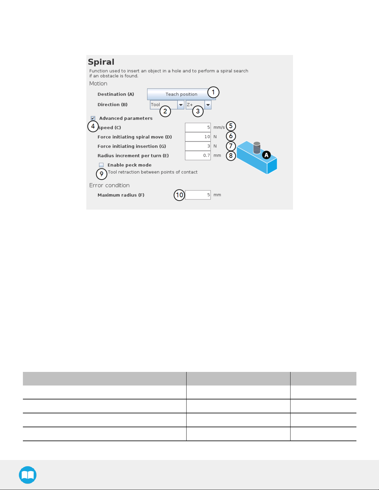
Features (Spiral)
The Spiral child node is packaged with an On error condition line to be populated with a program instruction when/if the error
condition occurs. The potential sequence after the Spiral instruction is followed by a program halt, by default.
1
Teach position button (Destination):Tapping this button saves the object's destination as a waypoint in the robot program
2
Reference frame dropdown menu (Direction):Menu used to select the frame according to which the tool will move in space
3
Axis dropdown menu (Direction): Menu used to select the direction in which the tool will go to reach the destination
4
Advanced parameters box: Box that expands the advanced parameters menu when ticked
5
Speed parameter: Textbox for the user to enter a speed value
6
Force initiating spiral move parameter:Textbox for the user to enter a force threshold value that triggers the spiral move,
after the part/tool has established contact with the mating part/surface
7
Force initiating insertion parameter: Textbox for the user to enter a force drop value indicating that the part/tool has found
the path of least resistance, prior to completing the insertion process
8
Radius increment per turn parameter: Textbox for the user to enter the distance between each spiral turn on the spiral radius
9
Enable peck mode box: Box that enables the retraction of the tool between points of contact
10
Maximum radius (Error condition): Textbox for the user to enter the maximum radius of the spiral, considering that no path of
least resistance has been found
Default values and units of measurement
Parameter Unit of measurement Default value
Reference frame (Direction) N/A Tool
Axis (Direction) N/A Z+
Speed mm/s 5
Force initiating spiral move N 10
FT300 Force Torque Sensor - Instruction Manual
Page 61
Parameter Unit of measurement Default value
Force initiating insertion N 3
Radius increment per turn mm 0.7
Maximum radius (Error condition) mm 5
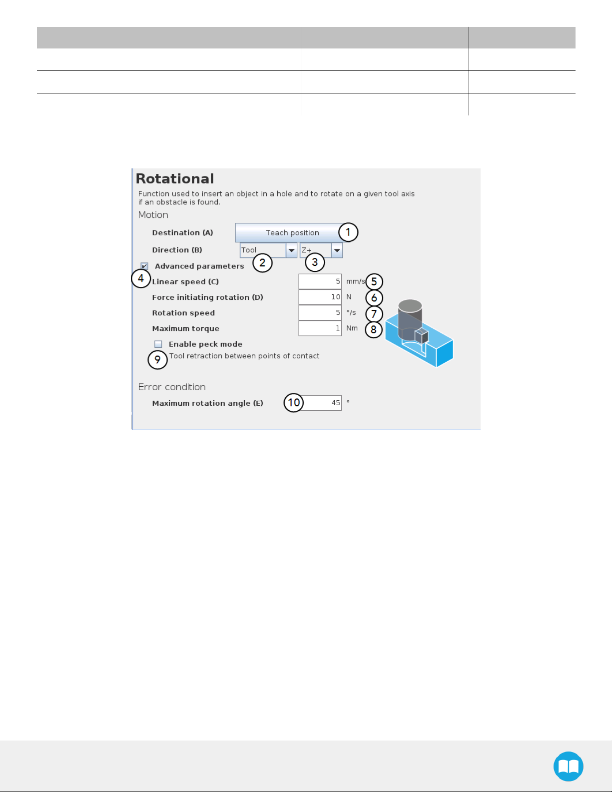
Features (Rotational)
61
1
Teach position button (Destination):Tapping this button saves the object's destination as a waypoint in the robot program
2
Reference frame dropdown menu (Direction):Menu used to select the frame according to which the tool will move in space
3
Axis dropdown menu (Direction): Menu used to select the direction in which the tool will go to reach the destination
4
Advanced parameters box: Box that expands the advanced parameters menu when ticked
5
Linear speed parameter: Textbox for the user to enter a speed value for the approach motion towards the destination
6
Force initiating rotation parameter: Textbox for the user to enter a force threshold value that triggers the rotation move, after
the part/tool has established contact with the mating part/surface
7
Rotation speed parameter: Textbox for the user to enter a speed value for the rotational (indexing) motion
8
Maximum torque parameter: Textbox for the user to enter a torque threshold value used to prevent potential collision with
objects during the rotational motion
9
Enable peck mode box: Box that enables the retraction of the tool between points of contact
10
Maximum rotation angle (Error condition): Textbox for the user to enter the maximum angle of the rotation motion, considering that no path of least resistance has been found
FT300 Force Torque Sensor - Instruction Manual
Page 62
62
Default values and units of measurement
Parameter Unit of measurement Default value
Reference frame (Direction) N/A Tool
Axis (Direction) N/A Z+
Linear speed mm/s 5
Force initiating rotation N 10
Rotation speed °/s 5
Maximum torque Nm 1
Maximum rotation angle (Error condition) ° 45
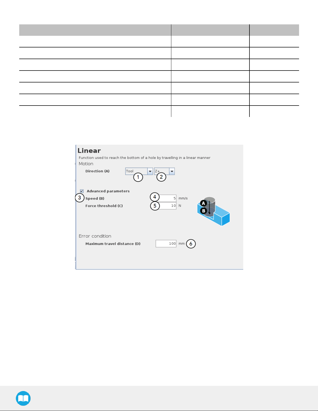
Features (Linear)
1
Reference frame dropdown menu (Direction):Menu used to select the frame according to which the tool will move in space
2
Axis dropdown menu (Direction): Menu used to select the direction in which the tool will go to reach the destination
3
Advanced parameters box: Box that expands the advanced parameters menu when ticked
4
Speed parameter: Textbox for the user to enter a speed value for the approach motion towards the destination
5
Force threshold parameter: Textbox for the user to enter a force threshold value that completes the linear motion
6
Maximum travel distance (Error condition):Textbox for the user to enter the maximum distance value which, upon being
reached, means the force threshold has never been reached in the linear motion
FT300 Force Torque Sensor - Instruction Manual
Page 63

Parameter Unit of measurement Default value
Reference frame (Direction) N/A Tool
Axis (Direction) N/A Z+
Speed mm/s 5
Force threshold N 10
Maximum travel distance (Error condition) mm 100
4.1.5. Find Surface node
The Force Copilot software package includes the Find Surface node, which is a great tool for machine tending and various other
applications that require repeated accurate positioning of objects.
The default parameters of the function allow for a versatile demo or a quick test of the features while the advanced parameters
make it a more customizable asset.
63
How to add a Find Surface node
l From the PolyScope home page, tap Program Robot
l Create or load a robot program
l Go to the Structure tab and tap the URCaps submenu
l Select the Find Surface node
l Tap the Find Surface node in the robot program to edit it
1
Direction relative to the tool dropdown menu:Menu used to select the direction of the linear motion, relative to the tool
2
Zero Sensor Before Execution box: Box that inserts a Zero FT Sensor command right before the Find Surface instructions
3
Advanced parameters box: Box that expands the advanced parameters menu when ticked
FT300 Force Torque Sensor - Instruction Manual
Page 64

64
4
Motion speed parameter: Textbox for the user to enter a speed value for the approach motion towards the destination
5
Maximum distance traveled (Stop condition):Textbox for the user to enter the maximum distance value which, upon being
reached, means the force threshold has never been reached in the linear motion
6
Insert instruction textbox: Checkbox that inserts the corresponding stop condition in the robot program when ticked; its main
function is to facilitate the programming and improve the user experience
7
Force threshold (Stop condition): Textbox for the user to enter a force thershold value that completes the linear motion
8
Insert instruction textbox: Checkbox that inserts the corresponding stop condition in the robot program when ticked; its main
function is to facilitate the programming and improve the user experience
Parameter Unit of measurement Default value
Direction relative to the tool N/A Z+
Motion speed mm/s 5
Maximum distance traveled (Stop condition) mm 100
Force threshold (Stop condition) N 10
FT300 Force Torque Sensor - Instruction Manual
Page 65

65
Fig. 4.3: Find Surface node with stop condition(s)
FT300 Force Torque Sensor - Instruction Manual
Page 66
66
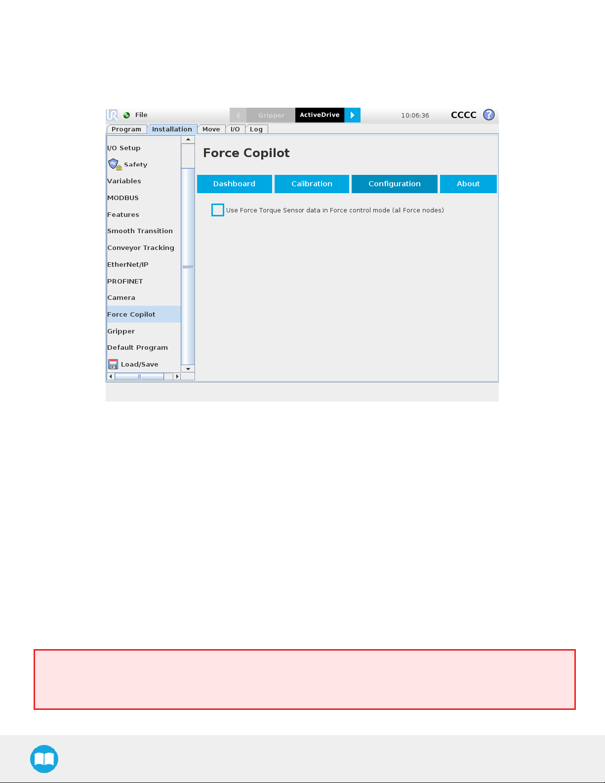
4.1.6. Using the Force Torque Sensor's Data in Force Nodes
In order to use the FTSensor's data in Force control mode for all Force nodes, go to the Configuration tab and check the
corresponding box. This will feed the Sensor's force values to the UR Force mode as an alternative to UR's embedded force
feedback.
4.1.7. Force ControlNode
Overview
The Robotiq Force Control node is used to apply force and torque values along and around axes.
How to add a Force Control node
l From the PolyScope home page, tap Program Robot
l Create or load a robot program
l Go to the Structure tab and tap the URCaps submenu
l Select the Force Control node
l Tap the Force Control node in the robot program to edit it
Warning
UR Move nodes (MoveL, MoveJ, MoveP)and Force nodes cannot be executed as child of the Robotiq Force Control
node.
FT300 Force Torque Sensor - Instruction Manual
Page 67

Tip
Where a URMove node would normally be used, the user shall record a Robotiq Path emulating the desired Move.
In a situation where the user wants to make contact with a surface in accordance with the user-defined settings, a Wait
instruction can be inserted as child of the Robotiq Force Control.
The Force Control node is primarily meant to be used with a Robotiq Path node.
With the various user-defined settings available, operators can use a force torque sensor to apply force/torque and thus follow
irregular shapes and/or surfaces for applications such as polishing, deburring, finishing, dispensing, etc.
67
FT300 Force Torque Sensor - Instruction Manual
Page 68

68
Features
Reference frame
The user can select a reference frame from a dropdown menu, as shown below.
The Tool reference frame uses the X, Y and Z axes of the end-effector to apply force and torque values in the appropriate direction.
On the other hand, the Base reference frame takes into consideration the X, Y and Z axes of the robot arm base.
Fig. 4.4: Force Control node with Reference Feature dropdown highlighted.
FT300 Force Torque Sensor - Instruction Manual
Page 69

Parameters
69
1
Enable control:each checkbox corresponds to the enablement of force feeding along an axis (upper three options) or torque
feeding around an axis (lower three options)
2
Force/Torque:depending on which options were checked at step 1, the corresponding textboxes here should be filled with
the desired force/torque values
a
Force values applied are in newtons (N) – the range allowed goes from -150 to +150 N
b
Torque values applied are in newton-metre (Nm) – the range allowed goes from -50 to +50 N.
Info
Tapping the text boxes brings up a numpad used to enter the values.
3
Stiffness:the stiffness settings act directly on the Sensor's directional compliance depending on the orientation of the endeffector and the axes selected at step 1.
a
A stiffness value closer to 0% will provide greater compliance along/around the corresponding axis
b
A stiffness value of 100% offers no compliance along/around the corresponding axis
4
Deviation range:the deviation range limits the flexibility allowed along/around the corresponding axis.
a
The deviation range along the X, Y and Z axes is measured in millimeters (mm) – the negative range allowed goes
from -1000 mm to 0 mm while the positive range allowed goes from 0 mm to 1000 mm.
b
The deviation range around the X, Y and Z axes is mesured in degrees (°) – the negative range allowed goes from
-179° to 0° while the positive range allowed goes from 0° to 179°.
Example
In a situation where 10 N are applied exclusively along the Z-axis, with 20% stiffness along the X and Yaxes, and a
deviation range that goes from -50 mm to +50 mm along all axes...
FT300 Force Torque Sensor - Instruction Manual
Page 70

70
l The end-effector will systematically point towards its Z-axis
l The end-effector will not rotate around Rx, Ry and Rz (no torque feeding)
l The end-effector will be moderately flexible to move along the X and Yaxes
l The movements along the X, Yand Z axes will be limited to -50 mm and +50 mm from the command position
Fig. 4.5: Deviation range - On the left, no deviation range has been entered. On the right, a deviation range of at least 15 degrees
has been entered around the corresponding axis.
5
Enable adaptive stiffness:this checkbox greys out the stiffness values in the boxes at step 3 since the Force Control calculates the rigidity of the surface/object with which the end-effector comes in contact. Thus, constant force/torque values are
applied to surfaces with variable rigidity (e.g.: long, bent, bending or folded sheets or parts.
When entering into contact with a surface for the first time, the end-effector will pull back for it has reached the force/torque
value entered at steps 2a and/or 2b. It will then go back to the surface and apply the same force/torque values while pulling
back less and less over time.
FT300 Force Torque Sensor - Instruction Manual
Page 71

71
Fig. 4.6: End-effector experiencing adaptive stiffness upon repeated contact with a surface
FT300 Force Torque Sensor - Instruction Manual
Page 72

72
Test
The Test button applies the user-defined settings of the Force Control node to the sensor, therefore moving along/around the
corresponding axes, if the control had been enabled for the latter, regardless of other instructions entered before or after the Force
Control node in the program tree.
FT300 Force Torque Sensor - Instruction Manual
Page 73

4.1.8. Multipoint Path Node
The Multipoint Path node is an advanced version of the Path node, combining complex trajectory recording and point-to-point
teaching, with the option to define each segment as a straight line or as a curve.
Tip
Try inserting a Multipoint Path node in a Robotiq Force Control node. The former will perform the movements that were
taught while taking into consideration the parameters set in the latter.
How to add a Multipoint Path node
l From the PolyScope home page, tap Program Robot
l Create or load a robot program
l Go to the Structure tab and tap the URCaps submenu
l Select the Multipoint Path node
l Tap the Force Control node in the robot program to edit it
73
Fig. 4.7: Multipoint Path node (empty)
Info
Please note that a Multipoint Path parent node is always followed by a MoveJ command leading to the starting
waypoint of the path sequence.
FT300 Force Torque Sensor - Instruction Manual
Page 74

74
How to set up a Multipoint Path
Step 1
l Select the MoveJ To waypoint child node in the program tree.
l A menu will display in the Command tab.
l Using the Freedrive mode or the URMove menu,move the robot arm to the position you want to be the starting point of your
Multipoint Path.
l Tap the Set waypoint button. The URwaypoint interface will pop up and ask you to define the waypoint.
l Adjust the position if needed, then press OK.
At this point, the interface will look like this:
1
Tap the Edit button to open the URwaypoint interface and adjust the position of the robot arm (this works for every waypoint of the Multipoint Path)
2
Tap the Delete button to cancel the waypoint (deleting the starting waypoint will turn it to unsassigned)
3
Tap and hold the Move here button to make the robot arm travel to the corresponding waypoint
4
Tap the Add line button to let the system know that a straight line will be linking the current waypoint and the next waypoint
5
Tap the Add curve button to let the system know that a curve will be linking the current waypoint and the next waypoint
Important
Whether the path is made of straight lines, curves or a mix of both, it inevitably passes through each waypoint set by the
user.
FT300 Force Torque Sensor - Instruction Manual
Page 75

Important
The curve segments are not generated and/or represented according to a spline model; they are rather based on Bézier
curves.
Info
For describing the continuity of the curves used in the Multipoint Path node, control points are generated on the bisector
of each waypoint junction (angle). Curves are therefore tangent to those bisectors.
Step 2
l Using the Freedrive mode or the URMove menu,move the robot arm to the next desired position.
l Add another waypoint in the program tree by tapping the Add line or Add curve button.
75
Fig. 4.8: Multipoint Path interface with Line/Curve options.
FT300 Force Torque Sensor - Instruction Manual
Page 76

76
Caution
Adding several waypoints (lines or curves) without moving the robot in between them will result in the generation of
identical waypoints.
In order to remedy this situation, the user can edit each waypoint created and adjust its position.
Tip
You can toggle at any time between the Line to waypoint and Curve to waypoint options.
Select the waypoint in the program tree and tap the appropriate radio button in the Command tab.
Repeat step 2 until you complete your Multipoint Path.
Fig. 4.9: Representation of a six-waypoint Multipoint Path with both curves and straight lines.
FT300 Force Torque Sensor - Instruction Manual
Page 77

4.2. Development Package
The Robotiq Force Torque Sensor development package can be downloaded at support.robotiq.com.
4.2.1. Distribution License
The development package is distributed under the New BSD license,which is a permissive free software license. In short, the
provided code can be used in any project without any restriction regarding its use (commercial or not). If it is included in a software,
this software does not need to be open-source. However, the code is provided "as is" without any liability from Robotiq and some
restrictions apply regarding the distribution of the code and the use of the Robotiq name.
The terms of the license (included in each source file) are described here:
Software License Agreement (BSD License)
Copyright (c) 2014, Robotiq, Inc. All rights reserved.
Redistribution and use in source and binary forms, with or
without
modification, are permitted provided that the following conditions are met:
77
- Redistributions of source code must retain the above copyright
notice, this list of conditions and the following disclaimer.
- Redistributions in binary form must reproduce the above
copyright notice, this list of conditions and the following
disclaimer in the documentation and/or other materials provided
with the distribution.
- Neither the name of Robotiq, Inc. nor the names of its
contributors may be used to endorse or promote products derived
from this software without specific prior written permission.
THIS SOFTWARE IS PROVIDED BY THE COPYRIGHT HOLDERS AND
CONTRIBUTORS
"AS IS" AND ANY EXPRESS OR IMPLIED WARRANTIES, INCLUDING, BUT NOT
LIMITED TO, THE IMPLIED WARRANTIES OF MERCHANTABILITY AND FITNESS
FOR A PARTICULAR PURPOSE ARE DISCLAIMED. IN NO EVENT SHALL THE
COPYRIGHT OWNER OR CONTRIBUTORS BE LIABLE FOR ANY DIRECT,
INDIRECT,
INCIDENTAL, SPECIAL, EXEMPLARY, OR CONSEQUENTIAL DAMAGES
(INCLUDING,
BUT NOT LIMITED TO, PROCUREMENT OF SUBSTITUTE GOODS OR SERVICES;
LOSS OF USE, DATA, OR PROFITS; OR BUSINESS INTERRUPTION) HOWEVER
CAUSED AND ON ANY THEORY OF LIABILITY, WHETHER IN CONTRACT,
FT300 Force Torque Sensor - Instruction Manual
Page 78

78
STRICT
LIABILITY, OR TORT (INCLUDING NEGLIGENCE OR OTHERWISE) ARISING IN
ANY WAY OUT OF THE USE OF THIS SOFTWARE, EVEN IF ADVISED OF THE
POSSIBILITY OF SUCH DAMAGE.
FT300 Force Torque Sensor - Instruction Manual
Page 79

4.2.2. Linux
Package Files – Description
The development package is structured with the following files and directories architecture (non-Linux files and directories are
ignored in this section):
l src: contains the source files common to all platforms
l obj: used during compilation for the object files related to the common sources
l Linux: contains Linux specific files
l bin: contains the binary files
l src: contains the source files common to all platforms
l main.c : application source file which can be modified by the user
l obj: contains all the object files after they are compiled
l Makefile: file containing the rules to compile the sensor driver using Make
Caution
79
When started, the provided software will scan all ports in the system (ttySx and ttyUSBx) to find a compatible Robotiq
device. It uses the Linux utility "fuser" to determine if the port is already opened. This section of code can be modified
by the user if necessary to avoid the scanning of ports (for example, if another device would become confused when
receiving a message that it cannot understand).
Procedure to Compile and Test the Provided Source Code
This procedure explains how to compile the source code and verify that the sensor data is properly read.
1. Unzip the package in the home folder, for example in the folder ~/driver/
2. Open a terminal and enter the package directory using the following command:
rd@debian:~/$ cd driver
3. Use Make to compile the application:
rd@debian:~/$ make linux
4. In order to have access to the virtual serial COM port, add the used username to the group dialout:
rd@debian:~/$ sudo usermod -a -G dialout username
5. It is required to log out (or reboot) the session in order for the group change to become effective.
FT300 Force Torque Sensor - Instruction Manual
Page 80

80
6. Make sure that the sensor is properly powered and that the data signals are connected to the development PC using the
provided RS485 to USB converter. A new device named ttyUSBx should be present in /dev, which can be verified with the following command:
rd@debian:~/$ ls -l /dev | grep ttyUSB
7. In a terminal, go to the ~/driver/Linux/bin folder and execute the demo application using the following command:
rd@debian:~/driver/Linux/bin/$ ./driverSensor
8. After 1-2 seconds, the sensor data should start showing up in the terminal as a vector of 6 floats with data in the (Fx, Fy, Fz,
Mx, My, Mz) format.
Fig. 4.10: Sensor Data Acquisition.
Adapt to a User Application
In practice, the provided source code will be adapted to either: be incorporated with a custom application or to communicate with
one. At this point, the main.c file should be adapted according to the guideline comments inserted in the code.
Caution
Please note that Robotiq can only support our customers in making sure they can compile and test the provided code as
is.
No support can be provided for the integration of the provided source code into a custom application.
FT300 Force Torque Sensor - Instruction Manual
Page 81

4.2.3. Windows
Package Files – Description
The development package is structured with the following files and directories architecture (non-Windows files and directories are
ignored in thissection):
l src: contains the source files common to all platforms
l obj: used during compilation for the object files related to the common sources
l Windows: contains Windows specific files
l bin: contains the binary files
l src: contains the source files common to all platforms
l main.c : application source file which can be modified by the user
l obj: contains all object files after they are compiled
l Data_logger: contains an application (and its source code) to log data from the sensor
l compiler.bat: script which automates the settings for the environment variables and the compilation of the example applic-
ation
81
l Makefile: file containing the rules to compile the sensor driver using Make
Procedure to Compile and Test the Provided Source Code
This procedure explains how to install MinGW, compile the provided source code and verify that the sensor data is properly read.
1. Unzip the package in the desired directory.
2. If it is not already installed, download MinGW at http://www.mingw.org/. Download the installer "mingw-get-setup.exe".
3. Install MinGW by running "mingw-get-setup.exe" and save the default installation path.
4. Open "MinGW installation manager".
5. Select "mingw-developer-toolkit" in the "Basic setup" tab and click "Mark for Installation".
6. Select "mingw32-binutils" in the "All packages" tab and click "Mark for Installation".
7. In the menu "Installation", click "Apply changes". This will install the required packages to compose the software using
Make.
8. In the Windows directory, run the compiler.bat file. This will build your application.
9. Run the application "driverSensor" located in the "Windows/bin/" folder.
10. After 1-2 seconds, the sensor data should start showing up in the command window as a vector of 6 floats with data in the
(Fx, Fy, Fz, Mx, My, Mz)format.
Fig. 4.11: Sensor Data Acquisition Under Windows.
FT300 Force Torque Sensor - Instruction Manual
Page 82

82
Adapt to a User Application
In practice, the provided source code will be adapted to either: be incorporated with a custom application or to communicate with
one. At this point, the main.c file should be adapted according to the suggested comments inserted in the code.
Caution
Please note that Robotiq can only support our customers in making sure they can compile and test the provided code as
is.
No support can be provided for the integration of the provided source code into a custom application.
FT300 Force Torque Sensor - Instruction Manual
Page 83
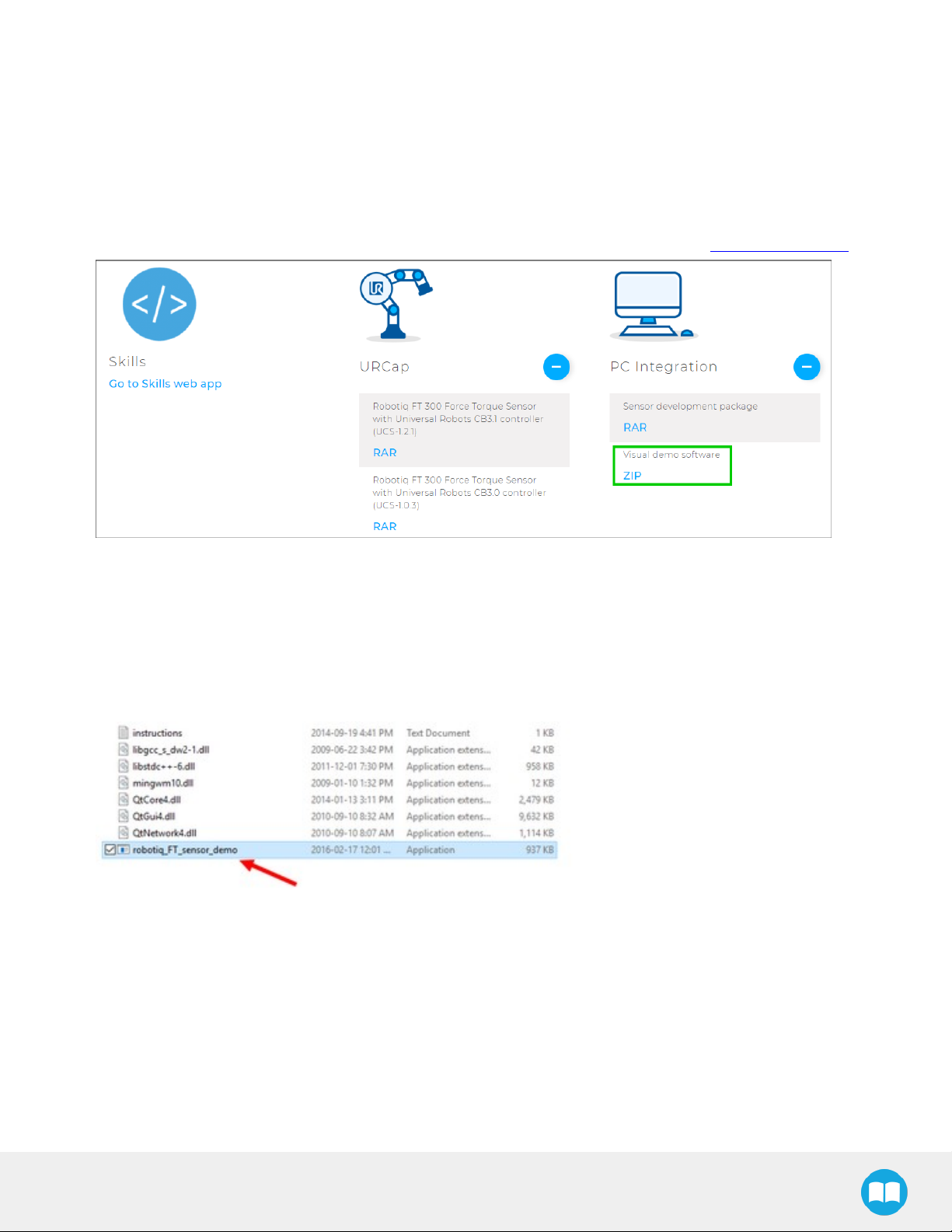
4.3. Visual Demo Software
The Visual Demo Software is used to demonstrate the ability of the FT Sensor to read force and moment. It is not intended to be
used for programming or to save or use data. It can also be used to calibrate the Sensor. Please refer to the Calibration Procedure
for the Visual Demo Software (PC) section for the calibration procedure.
4.3.1. Software Package Installation
1
Make sure that you have the latest version of the Visual Demo Software, which can be found at support.robotiq.com.
83
2
Copy all the files of this folder onto a PC.
3
Connect the USB connector to the converter attached to the PC. Important : The Sensor must NOT be powered at this time.
4
Wait while the driver(s) install. After all the drivers have been installed.
5
Plug the Sensor cable into the Sensor.
6
Connect the Sensor cable to the power supply.
7
Launch the demo application.
FT300 Force Torque Sensor - Instruction Manual
Page 84

84
8
You should see a COM port in green with a serial number, showing the Sensor connected to the PC. Click on it.
By going into the Sensor Data tab, you can now see in real time the force and moment applied on the FT Sensor.
FT300 Force Torque Sensor - Instruction Manual
Page 85

4.4. Serial Communication
The FT Sensor uses two communication modes, Modbus RTU and data stream. The Modbus RTU communication mode is used
to obtain information on the Sensor, like its firmware version. The data stream mode is used to obtain data from the Sensor.
Info
It is recommended to use the FT Sensor data stream to obtain faster data acquisition.
Caution
Modbus RTU can be used to obtain data, but will result in a slower data acquisition frequency.
Info
In both modes, force and torque data from the Sensor will be in 16-bits signed integer format.
85
4.4.1. Modbus RTU
The FTSensor can be controlled over USBusing an ACC-ADT-USB-RS485 signal converter. This section is intended to provide
guidelines for setting up a Modbus scanner that will adequately communicate with the Sensor.
For a general introduction to Modbus RTUand for details regarding the CRCalgorithm, the reader is invited to read the Modbus
over serial line specification and implementation guide available at:: http://www.modbus.org/docs/Modbus_over_serial_line_V1_
02.pdf.
For debugging purposes, the reader is also invited to download one of many free Modbus scanners such as the CASModbus
Scanner from Chipkin Automation Systems available at: http://www.store.chipkin.com/products/tools/cas-modbus-scanner.
Info
Modbus RTUis a communication protocol based on Big Endian byte order. Therefore, the 16-bit register addresses are
transmitted with the most significant byte first. However, the data port is, in the case of Robotiq products, based on the
Little Endian byte order. As such, the data parts of Modbus RTUmessages are sent with the less significant byte first.
Tip
Modbus RTUspecification and details can be found at www.modbus.org
FT300 Force Torque Sensor - Instruction Manual
Page 86

86
Connection Setup
The following table describes the connection requirements for controlling the Sensor using the Modbus RTU protocol:
Propriety Value
Baudrate (bps) 19,200
Data bits 8
Stop bit 1
Parity None
Supported Functions Read Holding Register (FC03)
Preset Multiple Register (FC16)
Slave ID 0x0009 (9)
In Modbus RTU you can obtain the following information:
Information Register
Production year- 514
Serial number 510 to 513
Force X (N) = value / 100 180
Force Y (N) = value / 100 181
Force Z (N) = value / 100 182
Moment X (Nm) = value / 1000 183
Moment Y(Nm) = value / 1000 184
Moment Z (Nm) = value / 1000 185
Acceleration X (g) = value / 1000 190
FT300 Force Torque Sensor - Instruction Manual
Page 87

Information Register
Acceleration Y (g) = value / 1000 191
Acceleration Z (g) = value / 1000 192
87
FT300 Force Torque Sensor - Instruction Manual
Page 88

88
Read Holding Register (FC03)
Function code 03 (FC03) is used to read the status of the Sensor (robot input).Examples of such data is the display of the current
force and torque values.
Example of FC03 Read Function:
To get Fx, you need to read (03) the register 180 (00B4) in device ID 9 (09).
Request is:09 03 00 B4 00 01 C5 64
Hex format:0x09 0x03 0x00 0xB4 0x00 0x01 0xC5 0x64
Bits Description
09 SlaveID
03 Function Code 03 (Read Holding Register)
00B4 Address of the first requested register
0001 Number of registers requested (1)
C564 Cycle Redundancy Check (CRC)
To get all 6 force/torque values at once, you need to read (03) six registers (0006), starting with register 180 (00B4) in device ID 9
(09).
Request is:09 03 00 B4 00 06 04 A6
Hex format:0x09 0x03 0x00 0xB4 0x00 0x06 0x84 0xA6
Bits Description
09 SlaveID
03 Function Code 03 (Read Holding Register)
00B4 Address of the first requested register
0006 Number of registers requested (6)
04A6 Cycle Redundancy Check (CRC)
FT300 Force Torque Sensor - Instruction Manual
Page 89

4.4.2. Data Stream
Data stream mode is the recommended method of obtaining data from the Sensor. Once initiated, the Sensor will stream force
and moment data continuously until communication is interrupted by the user.
Tip
To start the data stream, write 0x0200 in register 410.
For a setup over Universal Robots, Data stream will be accessible on TCP port 63351 of your machine.
Tip
With a Universal Robot, you can access the data stream using the documentation available at UR : Remote Control Via
TCP/IP - 16496
To stop the data stream, communication must be interrupted by sending a series of 0xff characters to the Sensor. Sending for
about 0.5s (50 times) will ensure that the Sensor stops the stream.
When the stream is started, 16 bytes messages are sent by the sensor at 100Hz using this format:
<0x20><0x4e><LSB_data1><MSB_data1> ... <LSB_data6><MSB_data6><LSB_crc><MSB_crc>
89
With dataX being a 16-bits signed integer defined as:
Data Value meaning
data1 Fx * 100 (N)
data2 Fy * 100 (N)
data3 Fz * 100 (N)
data4 Mx * 1000 (Nm)
data5 My * 1000 (Nm)
data6 Mz * 1000 (Nm)
The CRC is computed using a standard 16-bits modbus CRC (see http://www.ccontrolsys.com/w/How_to_Compute_the_
Modbus_RTU_Message_CRC).
Preset Multiple Registers (FC16)
Function code 16 (FC16) is used to activate functionalities of the Gripper (robot output).A common example is the initialization of
data streaming.
Example of setting multiple registers (FC16):
To initialize the data stream, 0x0200 must be written with the function 16 (0x10) in register 410 (019A).
FT300 Force Torque Sensor - Instruction Manual
Page 90

90
Request is: 09 10 01 9A 00 01 02 02 00 CD CA
Hex format: 0x09 0x10 0x01 0x9A 0x00 0x01 0x02 0x02 0x00 0xCD 0xCA
Bits Description
09 SlaveID
10 Function Code 16 (Preset Multiple Registers)
019A Address of the first register
0001 Number of registers requested (1)
02 Number of data bytes to follow (1 registers x 2 bytes/register = 2 bytes)
0200 Value written to register 0x019A
CDCA Cycle Redundancy Check (CRC)
FT300 Force Torque Sensor - Instruction Manual
Page 91

5. Specifications
The following sections provide data on the various specifications of the Robotiq Force Torque Sensor.
l Section 5.1 details the technical dimensions of the sensor.
l Section 5.2 details the mechanical specifications.
l Section 5.3 covers signal specifications (data acquisition).
l Section 5.4 specifies electrical rating.
l Section 5.5 covers the technical dimensions of the sensor coupling options.
5.1. Technical Dimensions
91
Fig. 5.1: Robotiq FT 300 Sensor general technical dimensions.
Info
Reminder: Measures are in millimeters.
FT300 Force Torque Sensor - Instruction Manual
Page 92

92
5.1.1. Tool Side Bolt Pattern
The figure below illustrates the bolt pattern used for tool fixation on the FT 300 Sensor.
l Bolt pattern diameter is 50 mm
l Mounting holes are M6 thread, 6 mm deep.
l Indexing hole for M6 dowel pin has a tight fit (H7) and 6 mm deep.
l Outside diameter of the flange is 64 mm and inside is 45 mm.
Info
FT 300 tool side bolt pattern matches ISO-9409-1-50-4M6.
Fig. 5.2: FT 300 Sensor tool side bolt pattern.
FT300 Force Torque Sensor - Instruction Manual
Page 93

5.2. Mechanical Specifications
Info
Reminder: all units are within the metric measurement system.
SPECIFICATION VALUE
Approximate weight 300 g
A combined load exceeding 500% of the measuring range will
Overload capacity
(Fx/300 + Fy/300 + Fz/300 + Mx/30 + My/30 + Mz/30 < 500%)
Outside diameter 75 mm
permanently damage the Force Torque Sensor
93
Through-hole diameter N/A
Thickness 37.5 mm
IPrating
Fx, F
F
z
y
35 X 106N/m
30 X 106N/m
43
1
Stiffness
y
Mx, M
M
z
1
Expected rating, certification is planned and will be forthcoming (see manual revision date).
10,000 Nm/rad
20,000 Nm/rad
FT300 Force Torque Sensor - Instruction Manual
Page 94

94
5.2.1. Moment of Inertia and Center of Mass
The coordinate system used for calculating the moment of inertia and center of mass for the FT Sensor is shown in the figure
below.
Info
All values are approximate. Actual coordinates may vary according to various options present on the Sensor.
Here is the approximate position of the center of mass for the FT Sensor:
Sensor Combination x (mm) y (mm) z (mm) Mass (g)
- 0 0 17 300
2-Finger 85 0 0 76 1205
2-Finger 140 0 0 83 1275
FT300
Wrist Camera 0 2 30 530
Wrist Camera and 2-Finger 85 0 1 77 1275
Wrist Camera and 2-Finger 140 0 1 85 1340
Here is the approximate moment of inertia matrix for the FT Sensor, taken at the coordinate system origin:
Fig. 5.3: Moment of inertia of the FT 300 Sensor.
FT300 Force Torque Sensor - Instruction Manual
Page 95

5.2.2. Overload Capacity
The FT 300 sensors have overload capacities, the overload capacity specification includes load and torque values in all 3 axes.
Info
For loads between the measuring range and the overload capacity, the signal will be saturated. The sensor will not
undergo permanent damage if the overload capacity is not reached.
Warning
Exceeding the overload capacity will permanently damage the sensor.
95
Sensor Measuring range
FT 300 +/- 300 N
1
Overload capacity with all axes combined.
2
Maximum load expressed in % of measuring range.
Overload capacity
1500 N (500%)
1
2
The overload capacity given includes forces and torques in all 3 axes. To get an approximation of the total load, these formulas
must be used:
l For the FT 300
Fx/300 + Fy/300 + Fz/300 + Mx/30 + My/30 + Mz/30 < 500%
FT300 Force Torque Sensor - Instruction Manual
Page 96

96
5.3. Signal Specifications
SPECIFICATION
Force ±300 N
Measuring range
Torque ± 30 Nm
Fx, Fy 1.2 N 0.1 N
Fz 0.5 N 0.1 N
Signal noise*
Mx, My 0.02 Nm 0.005 Nm
Mz 0.03 Nm 0.003 Nm
FT300
FT300
(prior to 10/2017)
Fx, Fy 5 N 1 N
Fz 2 N 1 N
Recommended threshold
Mx, My 0.08 Nm 0.02 Nm
Mz 0.12 Nm 0.01 Nm
External noise sensitivity** Immune
Data output rate
Temperature compensation*** 15 to 35 °C
*Signal noise is the standard deviation of the signal measured over a period of one (1) second
**Under normal operating conditions
***Within this range, the temperature fluctuation is compensated for; signal quality may be affected outside of this range
100 Hz
FT300 Force Torque Sensor - Instruction Manual
Page 97

Caution
The recommended threshold represents the smallest variations that can be detected by the sensor.
The signal noise is the limiting factor for the Sensor's precision.For the FT 300, the signal noise defined in the signal specifications
is the standard deviation of each data (Fx, Fy, Fz, Mx, My, Mz) over 1 second. In order to use that signal noise information, three
times the standard deviation given must be used. According to the normal distribution, three times the standard deviation will
cover almost all values possible (99.7%).
Info
Noise is an unwanted and unpredictable alteration to a signal. It may come from electrical or electromagnetic sources
and degrades the quality of the Sensor's signal.
97
FT300 Force Torque Sensor - Instruction Manual
Page 98

98
5.4. Electrical Ratings
SPECIFICATION VALUE
Input voltage 5 to 24 V DC ± 10%
Max power consumption 2 W
Communication electrical interface RS-485
Recommended fuse Phoenix #0916604 (UT6-TMC M 1 A)
Recommended power supply TDK-Lambda DPP Series 15W Single Output DIN Rail Mount Power Supply,
DPP15-24
FT300 Force Torque Sensor - Instruction Manual
Page 99

5.5. Couplings
For a detailed list of available couplings and adapter plates, please refer to the Spare Parts, Kits and Accessories section.
The following subsections contain data required for custom couplings or creating couplings from blanks.
Info
All Robotiq couplings and adapter plates are provided with necessary hardware for fixation on the Robotiq device side.
Caution
Unless identified for specific packages only, robot side screws and indexing pins are not provided.
99
FT300 Force Torque Sensor - Instruction Manual
Page 100

100
5.5.1. Blank Coupling
The figure below schematics represent the optional blank coupling for the FT 300 Sensor :
l (7) M4 threads and the 63 mm (H8) circle are meant to affix the FT 300.
l The circular section of 75 mm diameter (blue section in the figure below) represents the customization area and has a depth of 5
mm.
Warning
Make sure your custom design does not interfere with the M4 threads or the 63 mm, H8 centering circle.
l Spare part list number is FTS-300-CPL-BLANK.
l
Fig. 5.4: Technical dimensions of the blank coupling for the FT 300.
FT300 Force Torque Sensor - Instruction Manual
 Loading...