

Page 1

Robotiq EPickVacuumGripper
forTM Robots
Original Notice
© 2019Robotiq Inc.
Instruction Manual
robotiq.com | leanrobotics.org
Page 2

Revisions 5
1.GeneralPresentation 7
1.1. Grippernomenclature 7
1.1.1. EPick Gripper 7
1.1.2. Suction Cup System 8
1.2. Object picking 9
1.2.1. Main unit suction cup 9
1.2.2. Auxiliarysystem with multiple suction cups 9
1.3. Setupandcontrol 9
2.Safety 11
2.1. Warning 12
2.1.1. Risk assessment and final application: 12
2.2. IntendedUse 13
2
3.Installation 14
3.1. ScopeofDelivery 14
3.1.1. Robotiq EPick Vacuum Gripper Kit 14
3.2. RequiredToolsandEquipment 16
3.2.1. EPick Gripper Add-On 16
3.2.2. Suction cup system 16
3.3. Environmentaland OperatingConditions 16
3.4. MechanicalInstallation 17
3.4.1. Installing the Vacuum Gripper onto the robot 17
Single Gripper 17
3.4.2. Air tubing 18
Connectionof the suction cup systems 18
3.4.3. Suction cup system 19
Manifold and mounting bracket 19
Suction cupsand airnodes 20
3.5. ElectricalSetup 21
3.5.1. Pinout interface 21
3.5.2. Coupling to controller 22
Single VacuumGripper 23
3.6. Testingthe GripperwiththeRobotiqUserInterface (RUI) 24
EPick- InstructionManual
Page 3

3
3.6.1. License Agreement 26
4.Software 29
4.1. Overview 29
4.1.1. Control using registers 29
4.2. Vacuum Gripperregistermapping 31
4.3. Robotoutputregisters&functionalities 31
4.4. Robotinput registers& status 35
4.5. Gripperbehavior 38
4.5.1. Control modes 38
Automaticmode 38
Advanced mode 39
Veryporousmaterialdetection 41
Objectlost/ drop behavior 41
Objectsecured behavior 41
Objectnot detected behavior 42
Objectreleasedelay 42
Emergencystop behavior 42
4.6. Controllogic 42
4.7. ModbusRTU communication 42
4.7.1. Connection setup 43
4.8. ControloverTM 44
4.8.1. TM Robots compatibilitywith Robotiq Vacuum Grippers 44
4.8.2. Getting Started 44
4.8.3. TM Vacuum Gripper Components 48
Installation 48
GripperButton 53
Programming 56
Advanced Mode 57
GRIPComponent 58
RELEASEComponent 58
SelectID Component 59
Changing theModbusSlaveID 59
5.UserInterface 62
Page 4

6.Specifications 63
6.1. Technicaldimensions 64
6.1.1. Gripper 64
6.1.2. Suction Cup System 65
Manifold 65
Bracket for2 suction cups 65
Bracket for4 suction cups 66
6.1.3. Air nodes 68
6.1.4. Couplings 69
Blankcoupling 69
Coupling forISO 9409-1-50-4-M6 70
6.2. Mechanicalspecifications 71
6.2.1. Payload and force 72
4
Example1:Non-porousmaterial 75
Case#2 76
Example2:Porousmaterial 76
Case#1 78
6.2.2. Center of massand tool center point 79
6.2.3. Moment Limitation 80
6.3. Electricalspecifications 80
7.Maintenance 81
7.1. Vacuum Grippercleaning 82
7.2. Periodicinspection 83
Suction cupsand airnodes 84
8.Spare Parts, Kitsand Accessories 85
9.Troubleshooting 88
9.1. Vacuum Gripperverification 88
10. Warranty 89
11. Harmonized Standards, Declarationsand Certificates 91
11.1.OriginalECdeclarationofincorporation 91
11.2.Appliedstandards 92
12. Contact 93
EPick- InstructionManual
Page 5

5
Revisions
Robotiq maymodify thisproductwithout notice,whennecessary,due to product improvements,modificationsor changesin
specifications.If suchmodificationis made,themanual will also berevised,seerevision information.Seethelatest versionof this
manualonlineatsupport.robotiq.com.
2019/08/13
l Update of thelatestTMflow 1.72.3500
l Update of theversion V_002of thecomponents
2019/07/02
Initial release
Page 6

6
Copyright
© 2019Robotiq Inc.All rightsreserved.
Thismanualand theproduct it describesareprotected bytheCopyright Actof Canada,bylawsof othercountries,and by international
treaties,and thereforemaynot be reproduced in whole or inpart,whetherforsaleor not,without priorwrittenconsentfrom Robotiq.
Under copyright law,copying includestranslationinto anotherlanguage or format.
Information provided byRobotiq in thisdocument is believed to be accurate and reliable.However,no responsibility is assumed by
Robotiq for itsuse.Theremaybe somedifferencesbetweenthe manualand theproduct if theproduct hasbeenmodified afterthe
editiondate.
Theinformation contained inthisdocument issubject to change without notice.
EPick- InstructionManual
Page 7

7
1.GeneralPresentation
Theterms“ Gripper”,"EPickGripper", " EPickVacuumGripper" and "EPick" used in thefollowing manual allreferto the Robotiq EPick
VacuumGripper.TheRobotiq EPick VacuumGripperisa robotic peripheral designedfor industrialapplications. Thevacuum is
generated withanelectricvacuum pump. Itsdesignmakesit a uniquerobotic end-of-arm tool to quicklypick,placeand handlea large
range of partsof varying sizesand shapes.
Info
Thefollowing section presentsthekeyfeaturesof the Gripperand must not be considered asappropriateto theoperation of
theGripper.Eachfeatureis detailed inthe appropriatesection.
Info
Thefollowing manualusesthemetricsystem.Unlessspecified, alldimensionsareinmillimeters.
1.1. Grippernomenclature
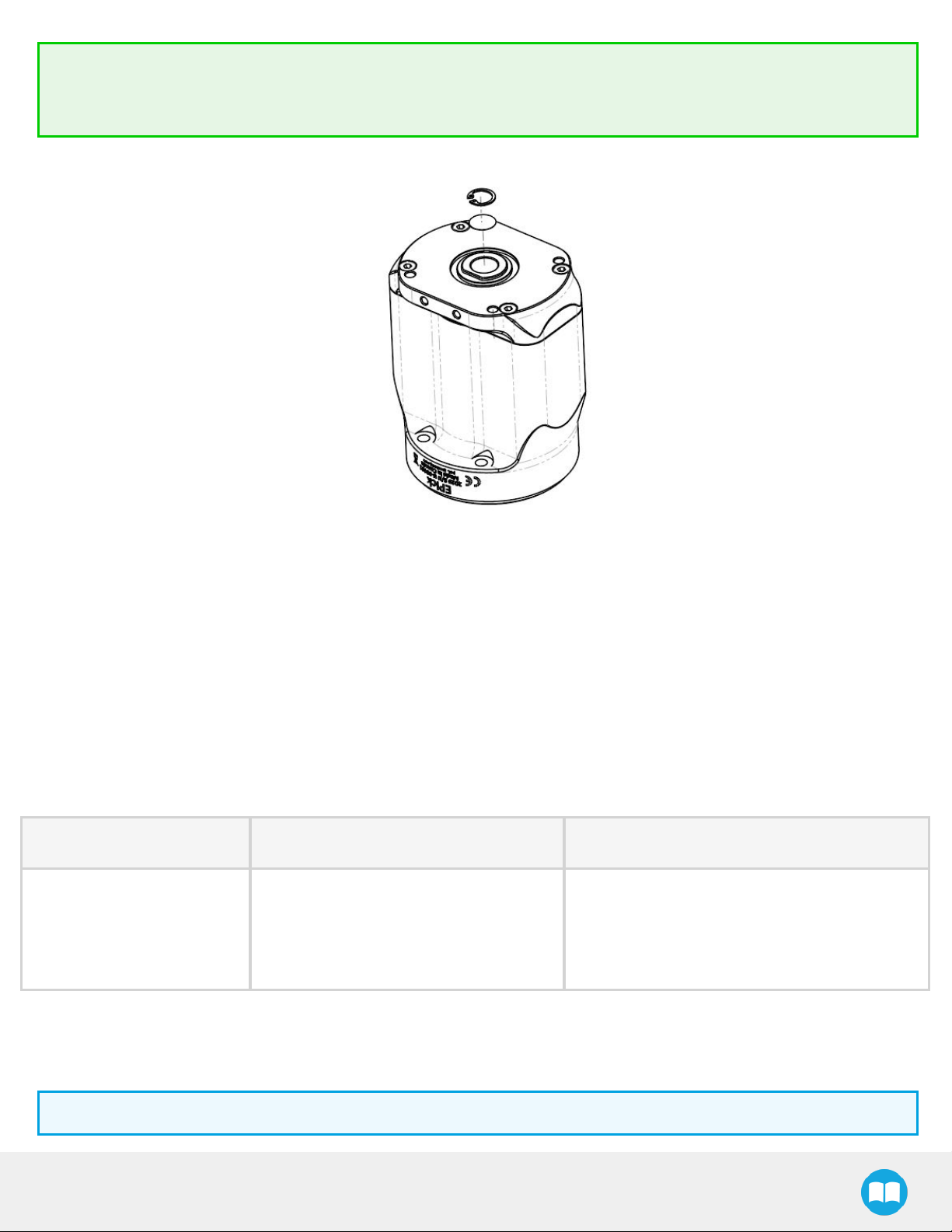
1.1.1.EPick Gripper
TheEPickGripperis avacuum Gripperthat generatesavacuum withanelectricvacuumpump..Itis equipped with oneormultiple
suction cups.Eachsuctioncup canbeadapted to your application and grasping needs.TheEPickGripperis compatible withthe
Robotiq standard coupling interface.
Fig. 1-1:Robotiq EPickGripper
EPick- InstructionManual
Page 8

8
Info
Pleasereferto theScope of Deliverysectionsubsection and the SpareParts, Kitsand Accessoriessection for detailson
standard andoptionalparts.
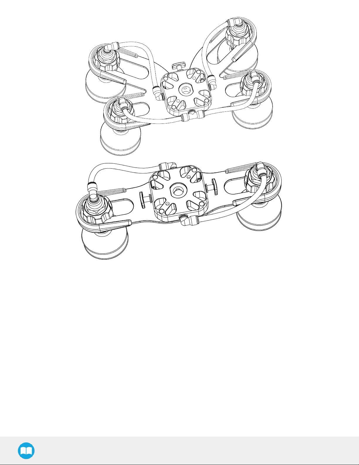
1.1.2.SuctionCupSystem
A Robotiq Suction Cup System can be installed directly under the Vacuum Gripper. Each Robotiq Suction Cup System includes a
bracket,a manifold, airnodes,port plugs,bumpers,tubing and additionalsuctioncups.
Fig. 1-2:Suction cup system
Info
Pleasereferto theInstallationsection for moreinformation on howto integratetheSuction Cup Systemto EPick.
Info
Pleasereferto theScope of Deliverysectionsubsection and the SpareParts, Kitsand Accessoriessection for detailson
standard andoptionalparts.
Tip
Theowner canusea custom bracketora mounting plate.Thebracketormounting plate canbeinstalled directlyunderthe
manifold.
Page 9

1.2.Object picking
TheEPickGripperallows:
1. Mainunitsuctioncup
2. Auxiliarysystem with multiple suctioncups
Warning
Objectpicking causesthecompression of thesuction cup(s),whichcanresultin pinching pointsbetweenthe gripperand the
load. Avoid presenceof bodypartsinthiszoneduring operation.
Warning
Before picking anynewobject or materialin autonomousmode,alwayscheckthat theresulting vacuumlevel issufficient to
ensuresafegripping,in order to prevent dropping or ejection of the load.
9
1.2.1.Mainunit suctioncup
Inorderto useonlyonesuction cup, thesinglecup canbe mounted right intheport of the vacuumgenerator.
1.2.2.Auxiliary systemwith multiplesuction cups
A standard Suction Cup Systemcanbe attached to theEPickVacuumGripper.Thebracket normallyholds two or foursuctioncups
(corresponding to thefourports of themanifold).
Anyunused manifold port should be blocked witha mating plug to avoid airleakage.
Othercustom mounting optionscanalso be used to benefit from a multiple suction cupssolution
Caution
Custom bracketsand platesmust meet therequired technical specifications(referto the Technicaldimensionssection
subsection).
1.3.Setupand control
TheVacuumGripper ispowered and controlled directlyviaa single devicecablethat carries24VDC powerand ModbusRTU
communication overRS-485.
Info
Pleasereferto theElectricalSetup section subsection for wiring information,and to the Softwaresection forthe control of the
VacuumGripper.
Inorderto be used,theEPickGripper hasto be connected to aGrippercoupling whichprovidesboth themechanicaland electrical
connectivityto the Gripper.
EPick- InstructionManual
Page 10

10
Info
Pleasereferto theMechanicalInstallationsection formoreinformation on mounting theVacuumGripperonto thecoupling.
Refer to the Technicaldimensionssectionfor thetechnical drawing,and referto theSpare Parts, KitsandAccessoriessection
for alist of theavailablecouplings.
TheEPickGripperboasts an embedded object detection featurewhichusesindirectsensing measurements.Thesystemthusindicates
if theworkpiecehasbeendropped or if theGripper failed to grasp theworkpiece.
Info
For moreinformation regarding theobject detection feature,please referto theSoftware section.
Page 11

2.Safety
Warning
Theoperatormusthaveread and understood all of theinstructionsinthe following manual beforeoperatingtheRobotiq
VacuumGripper.
Caution
Theterm“operator” refersto anyone responsiblefor anyof thefollowing operationson theRobotiq Vacuum Gripper:
l Installation
l Control
l Maintenance
11
l Inspection
l Calibration
l Programming
l Decommissioning
Thismanualcoversthevariouscomponentsof theRobotiq VacuumGripperand thegeneral operationsregarding thewholelife-cycle
of the product, from installation to operation and decommissioning.
Thedrawings and photosin thismanualarerepresentativeexamples.However,discrepanciesmaybe observed betweenthevisual
supportsand theactual product.
EPick- InstructionManual
Page 12

12
2.1. Warning
Caution
Anyuseof theGripperin non-compliancewiththesewarningsis deemed inappropriate and maycause injuryor damage.
Warning
l Alwaysusethe suctioncup system and its components(airnodes,port plug, etc.)withtheRobotiq VacuumGripperonly.
l Neveroperatethe VacuumGripperwithleaking orwornparts.
l TheVacuumGripper needsto be properlysecured beforeoperating the robot.
l Do not installor operate aGripperthatis damaged or lacking parts.
l Neversupply theGripperwith an alternating current source.
l Makesureall cord setsarealwayssecured at both ends—Gripperand robot.
l Alwaysmeet therecommended keying for electricalconnections.
l Makesureno individualsor assetsareinthe vicinityof the robot and/orGripperpriorto initializing therobot.
l Alwaysmeet theGripper’spayload specifications.
l Set yourvacuum levelbased on yourapplication.
l Keep body partsand clothing awayfrom theGripperwhilethedeviceispowered on.
l Do not usetheGripperon people or animals.
l Neverstand undersuspended loadsheld by theVacuumGripper.
2.1.1.Riskassessment andfinal application:
TheRobotiq Vacuum Gripperismeantto be used on cobotsand industrial robots.
Therobot, theGripper and anyotherequipment used in thefinal application must go througha comprehensiveriskassessment
processbeforetheycanbe used.Special caremust be takenduring thisstep if custom mounting optionsareused for thesuction cups.
Caution
Itis therobot integrator’sresponsibilityto ensure thatall localsafetymeasuresand regulationsaremet.
Thefollowing non-exhaustivelistpresentsrisksthatmustbeassessedduringtheintegration process:
l Riskof contact betweenbodypartsand suction cups during gripping;
l Riskof load ejection resultingfrom lossof vacuum;
l Riskof load dropping resultingfrom lossof vacuum;
Page 13

l Riskof pinching betweenthe VacuumGripperand thepart(s)ortheenvironment;
l Riskof damageor breaking if using acustom suction cup bracket thatdoesnot meet thetechnicalrequirements.
Depending on theapplication,there maybe hazardsthat requireadditionalprotection and/or safetymeasures.Forinstance,the
workpiecehandled bythe Grippercould beinherentlydangerousto the operator.
Warning
Depending on thesupply sources,whenanemergencystop (e-Stop)button is pressed, thefollowing consequencesmay
occur.Therobot ownerhasthe responsibility to do a riskassessmentand choosetheappropriateoption.
Supplysources e-Stop consequences
13
Robot tool supply
Powerfailureto theVacuum Gripper.Thevacuumlevelwilldrop to ambient pressureand the
objectwill be lost.
(tool connector)
VacuumGripper powered ON.
Robot controller supply
(Any24Vpin)
l Ifanobject isdetected: thevacuum levelwill continueto be regulated and theobject will
not be lost.
l Ifno object is detected:theVacuum Gripperwill go into astandby state 2 secondsafter
thee-Stop button ispressed.
Warning
Lossof vacuum canoccurdue to powerfailure.
2.2.Intended Use
TheGripperunit isdesigned for gripping and temporarilysecuring or holding objects.
Caution
TheGripperisNOT intended for applying forceagainstobjectsor surfaces.
Theproductis intended for installation on arobot or otherautomated machineryandequipment.
Info
Alwayscomplywith local,state,provinceand/or federallaws,regulation and directivesregarding automationsafetyand
generalmachinesafety.
Theunitshould be used exclusivelywithin therangeof itstechnicaldata.Anyotheruseof the productis deemed improperand
unintended.Robotiq will not be liablefor anydamagesresulting from anyimproperor unintended use.
EPick- InstructionManual
Page 14

3.Installation
Thefollowing subsectionswillguide you throughtheinstallation and generalsetup of yourRobotiq Vacuum Gripper.
Warning
Before installing:
l Read and understand thesafetyinstructionsrelated to theVacuumGripper.
l Verifyyourpackage according to the scope of deliveryandyourorder.
l Makesureto havetherequired parts,equipmentand toolslisted in Scope of delivery.
Warning
Wheninstalling:
14
l Meetthe recommended environmental conditions.
l Do not operate theVacuumGripper,oreventurnon thepowersupply,beforethedeviceisfirmlyanchored and themachine
areais cleared.Makesurethat theairsupply is secured.
3.1. Scope of Delivery
3.1.1.RobotiqEPickVacuumGripperKit
Standard upon delivery:
l Standard Kit
o
One(1)electricalvacuum generator
o
Two(2)standard suction cups(two different sizes)
o
One(1)End effectorcoupling kit
o
One(1)USBstick
o
One(1)USBto RS485signalconverter
o
One(1)RS485to RS232Converter
o
One(1)10-meterscommunicationcable
o
Required hardware
EPick- InstructionManual
Page 15

15
l 2SuctionCupsKit
o
One(1)Vacuumgenerator
o
One(1)suctioncup system for 2suction cups ( 1manifold,1 bracket, tubing, 2 airnodes,4 suctioncups)
o
Four(4)standard suction cups(two different sizes)
o
Four(4)port plugs (two alreadymounted on thesuction cup system)
o
One(1)End effectorcoupling kit
o
10-metercommunicationcable
o
One(1)USBto RS485signalconverter
o
One(1)RS485to RS232Converter
o
Required hardware
l 4SuctionCupsKit
o
One(1)Vacuumgenerator
o
One(1)suctioncup system for 4suction cups (1manifold, 1bracket,tubing,4 air nodes,8 suction cups)
o
Eight (8)standard suctioncups(two different sizes)
o
Four(4)port plugs
o
One(1)End effectorcoupling kit
o
10-metercommunicationcable
o
One(1)USBto RS485signalconverter
o
One(1)RS485to RS232Converter
o
Required hardware
Info
Pleasereferto theSpare Parts,Kitsand Accessoriessection for alist of available couplings.
Caution
Thefollowing are not included in thestandard delivery:
l Optionssuchascustom suction cup brackets/platesor couplingsfor mounting on variousindustrialrobots.
l Hardwarerequired for accessoriesor fixtures,unlessspecified.
Info
Whenpurchased asakit,theEPickVacuumGripperwill comein apackage withtheappropriatecoupling,suctioncupsand
cabling.
Page 16

Pleasereferto theSpare Parts,Kitsand Accessoriessection for additional components.
3.2. Required ToolsandEquipment
3.2.1.EPick Gripper Add-On
Thefollowing toolsarerequired to install theVacuum Gripper:
l Hexkeyto mount thecoupling onto therobot,according to yourcoupling
l 4mm hexkeyto mount theVacuum Gripperonto its coupling .
3.2.2.Suctioncupsystem
Thefollowing tool isrequired to install theSuction cup systemonthe VacuumGripper:
l 4mm hexkeyto assembletogetherthesuction cup systemand thevacuum generator.
16
3.3. Environmentaland Operating Conditions
CONDITION VALUE
Minimumstorage/transit
temperature
Maximumstorage/transit
temperature
Minimumoperating temperature 5°C[41°F]
Maximumoperating temperature 40°C[104°F]
Humidity (non-condensing) 20-80%RH
IPRating IP4X
Table3-1:Environmental and operating conditionsof the EPickVacuumGripper
-30°C[-22°F]
60°C[140°F]
Caution
Useof theVacuum Gripperis not recommended inpresence of chemicalsin theenvironment.
EPick- InstructionManual
Page 17

17
Info
Theinput filterprevents anydust larger than200 µm from getting insidethepump. Drydust will preventtheaccumulation on
filtersor inside thepump.Theuseof suction cups withintegrated filtercanbe used to reducedustaccumulation.
Theexhaustmustnot be blocked.
3.4.Mechanical Installation
3.4.1.InstallingtheVacuumGripperonto therobot
Single Gripper
For purposesof powerand communication,acoupling mustbeusedto attachtheVacuum Gripperto therobot.
Herearethestepsto follow to mount theGripper on therobot arm(exploded viewin figurebelow). Pleasenote thatall screwsshould
be secured using mediumstrengththreadlockers.
1. Mount thecoupling on therobot wristusing the provided M6 screwsand toothlockwashers.Alignproperlywith thedowelpin.
Thedowelpin ismeant to haveatight fit on therobot side and a slip fit on theeffector side of theassembly.
2. FastentheGripperto thecoupling usingtheprovided M5 screwsand tooth lockwashers.
3. Plug thedevicecableinto the gripper'spigtail andattachthecable along therobot armusing a cable routing system.
Page 18

18
Fig. 3-1:Installing the VacuumGripperonto therobot wrist
3.4.2.Air tubing
Connectionof the suctioncup systems
To ensurevacuumdistribution to the suction cups,connect theappropriatemanifold portswiththe pertaining airnodesusing the
provided plastictubing.
Info
To facilitatetheassemblyof theRobotiq Wrist Cameraon thesuction cup system,makesureto placethetubing asshownin
thefigureto be assured that therewill be no interferencewiththecamera'sfield of viewwhile preventing excessivetube
bending.
EPick- InstructionManual
Page 19
19
Fig. 3-2:Airtubesalignment
3.4.3.Suctioncupsystem
Manifold and mounting bracket
Inorderto usethetwo (2)or thefour(4)SuctionCupsSystem,assemble thevacuum generator to the suctioncup system,asshownin
thefigurebelow,using four(4)M5 socketheadcap screwsand four(4)M5 toothlockwashers.
Page 20

20
Fig. 3-3:Mounting exampleof thefoursuctioncupsassemblyon thevacuumgenerator
Warning
Anyunused manifold port should be covered with aprovided port plug to avoid airleakage.Formoredetails,pleasereferto
theManifoldsection
Suctioncupsand air nodes
Whether you are using astandard or custom option,airnodesshould beusedto connect thesuction cups and the air tubing,and to
preventair leakage asmuchaspossible.Airnodesareeasyto assemble,asshownin thefiguresbelow.
1. Screwbyhand eachprovided vacuum cup to an airbolt.
Fig. 3-4:Screwinga vacuumcup and anairbolt
2. Passeachair bolt throughthemounting bracket,adjust thepositionof thenode along thebracket side,alignwith mating airnuts
andtightennode byhand.
EPick- InstructionManual
Page 21
21
Fig. 3-5:Mounting airnodes(vacuum cups,airbolts,airnuts)on thebracket
3.5. Electrical Setup
Powerand communicationareestablished withtheGripperviaasingle devicecable.Thedevicecableprovidesa24Vpowersupply
andenablesserialRS-485communication to therobot controller.
Info
RS-485signals(485+,485-and 485GND)areisolated from the main 24 Vpowersupply.GND canbe connected to anyother
ground referenceaslong asthe voltage potentialbetweenthe groundsdoesnot exceed 250V.Grounding referenceisat the
user’sdiscretion.
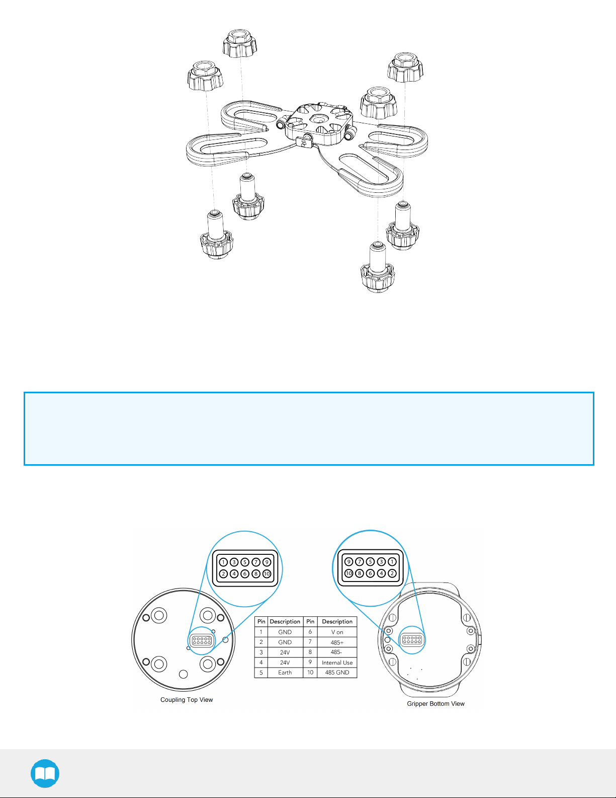
3.5.1.Pinout interface
TheGripperinterfaceswithitscoupling viaa 10-springpin connectorlocated on itsoutersurface.
Fig. 3-6:Pinout of the EPick cable-to-wristcoupling.
Page 22
22
Info
Thecoupling used inthe figureaboveisused for reference onlyand corresponds to bolt patternISO 9409-1-50-4-M6.
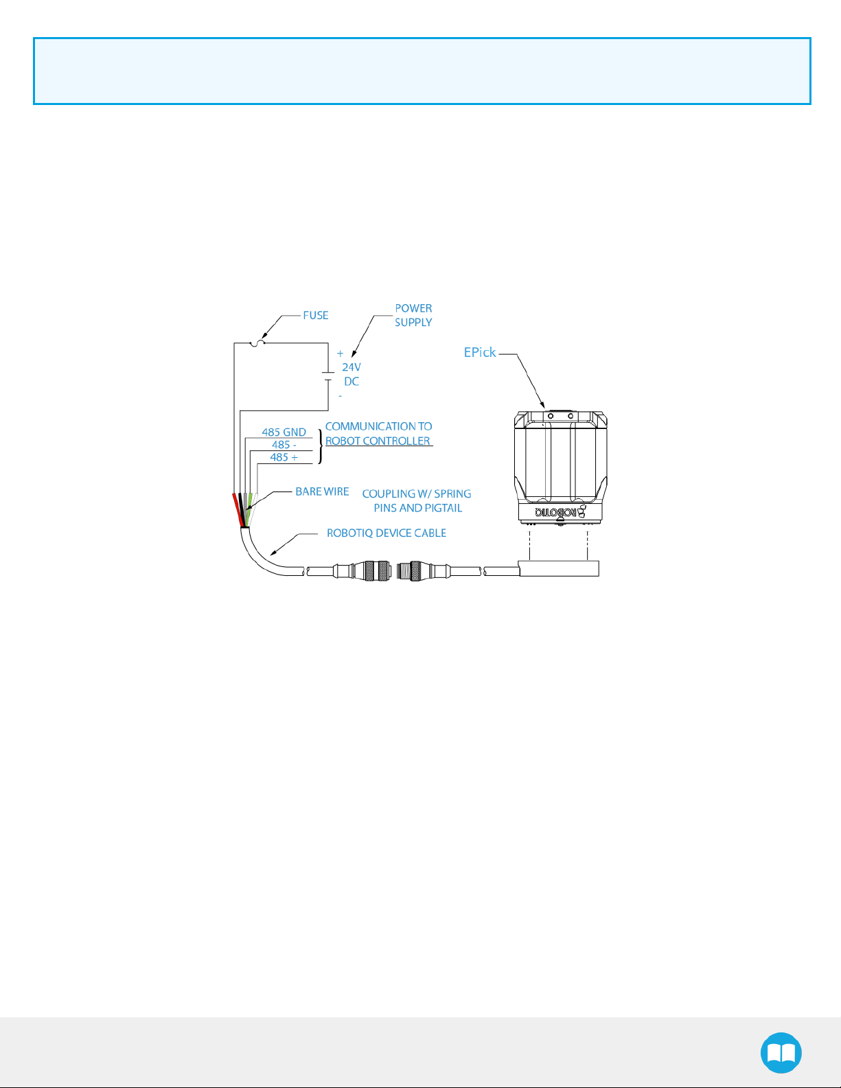
3.5.2.Couplingto controller
Anoptional Robotiq Universal Controllermaybe used betweenthe Gripperand thenetwork/robot controller if fieldbus
communication is required.
Ifa Robotiq Universal Controllerisused, pleasereferto theinstructionmanual of the Robotiq UniversalController.Thefigurebelow
representsthe wiring schemeof theVacuum Gripperwithdevicecable,powersupply,fuse (referto theRequiredToolsand Equipment
section)and grounding.
Fig. 3-7:Robotiq Vacuum Gripperwithpigtail cable and devicecable wiring scheme.
EPick- InstructionManual
Page 23
23
Caution
Useproper cabling management.Makesure to leave enough slackinthecabling to allowmovement of theGripperalong all
axeswithoutpulling out theconnectors.Alwaysprotect thecontrollerside (robot side)connector of the cable with astrain
relief cable clamp.
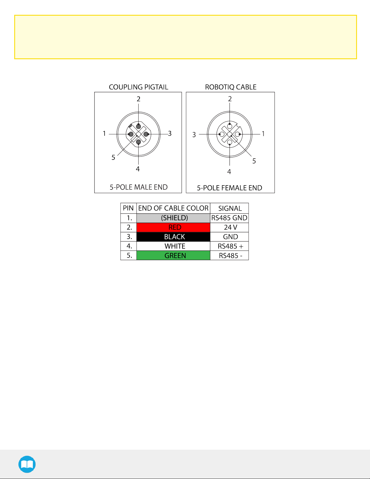
Thefigurebelowillustratesthe VacuumGripperpigtail connectorfrom thecoupling (GRP-CPL-062or AGC-CPL-XXX-002),the device
cable on therobot side (CBL-COM-2065-10-HF)and theirassociated pinout.
Fig. 3-8:Pinout of the VacuumGripperpigtail and devicecable
Ifadditionalcablesare used,suggested cable specificationsare:
Powersupply, fusing
l Minimum#22AWG TEW,300Vor 600V
RS485signal
l Minimum#24AWG TEW,300Vor 600V
l A and Bsignalsmust be balanced at 120Ohms
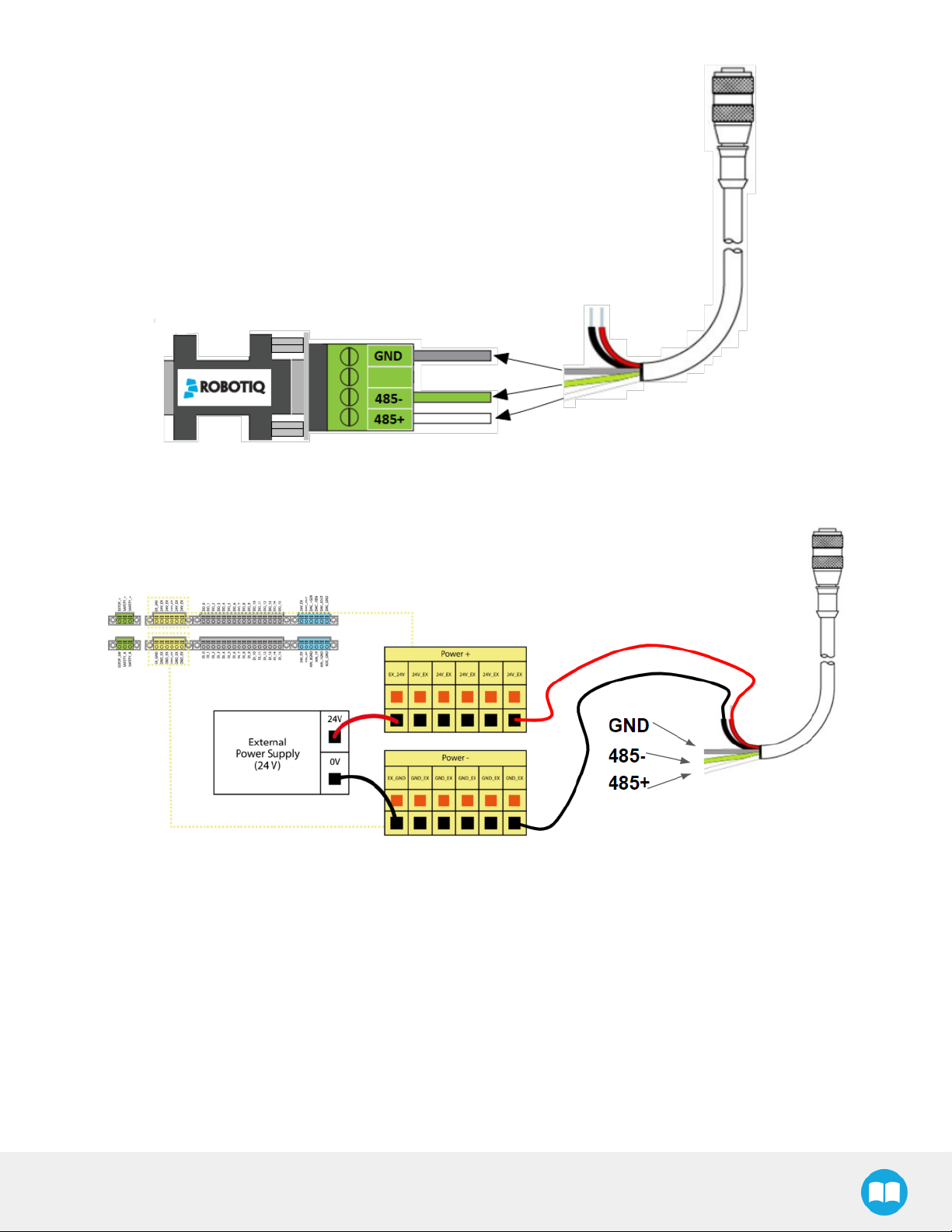
Single VacuumGripper
Connect the white, green and bare wires to the Robotiq RS485 to RS232 signal converter (ACC-ADT-RS232-RS485) as shown in the
figurebelow.
Page 24
24
Fig. 3-9:Grippercableto RS485/RS232converter
Also connectthe red (24V)and black(0V)wiresin thecontrolleraccording to the figurebellow.
Fig. 3-10:Grippercableto terminal connectoron thecontroller
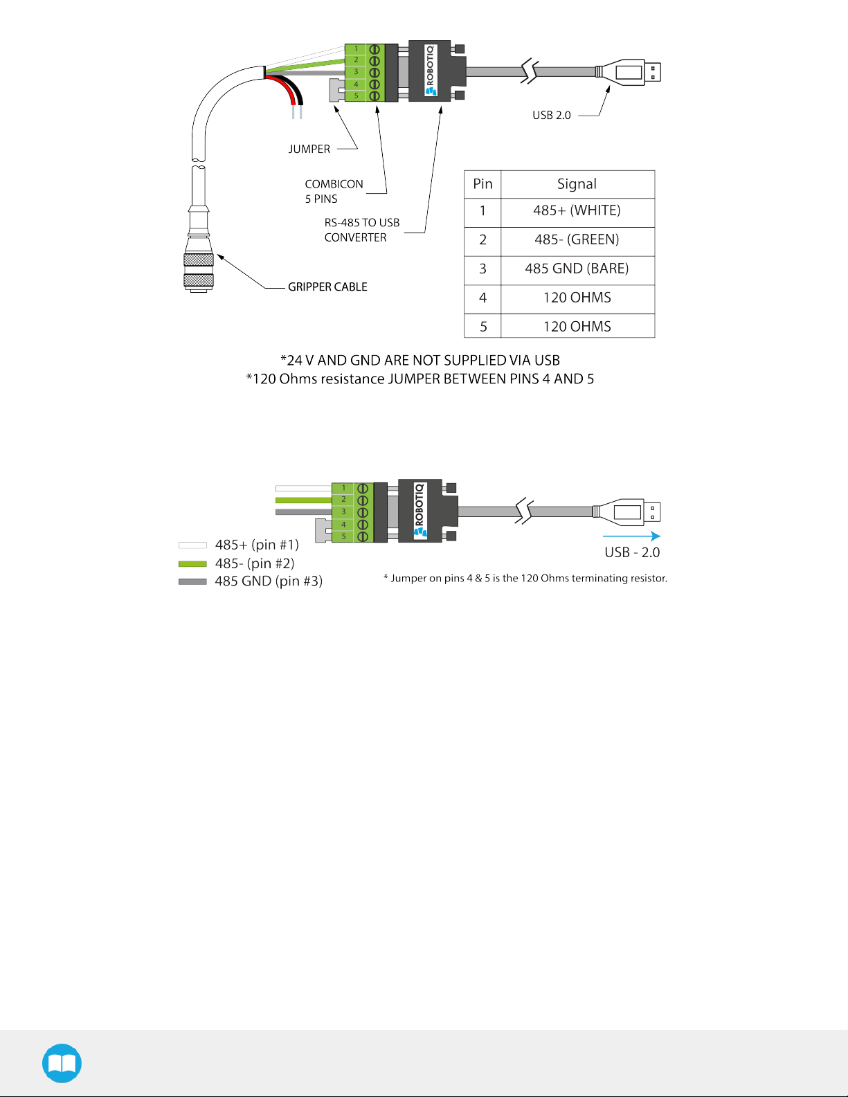
3.6.Testingthe Gripperwiththe Robotiq UserInterface (RUI)
Onceinstalled and properlysecured, yourRobotiq Vacuum Grippershould be tested with theRobotiq UserInterfacetestsoftware
using theprovided USBconverter.To do so :
EPick- InstructionManual
Page 25
25
Fig. 3-11:Wiring possibilitiesof theUSBto RS-485converter.
Fig. 3-12:Wiring possibilitiesof theUSBto RS-485converter.
Page 26

3.6.1.License Agreement
END-USERLICENSEAGREEMENT
YOUSHOULD CAREFULLYREAD THEFOLLOWINGAGREEMENTBEFOREUSINGTHESoftware(asthistermis hereinafter
defined).Using theSoftwareindicatesyour acceptanceof the agreement. If youdo not agreewithit,youarenot authorized to usethe
Software.
IMPORTANT-READ CAREFULLY:ThisEnd-UserLicenseAgreement(the“ Agreement”)isa legalagreement betweenyou and the
Licensor (asthistermishereinafterdefined),thelicensor of the Software.ThisAgreement coverstheSoftware.The Softwareincludes
any“ on-line” orelectronicdocumentationand allmodificationsand upgradesrelated thereto.Byinstalling,or otherwiseusing the
Software,you agreeto bebound by thetermsof thisAgreement.Ifyou do not agreeto the termsof thisAgreement,theLicensor
cannot and doesnot license theSoftwareto you.Insuch event,you must not useor installtheSoftware.
1. Definition.
1. “TM” meansTechmanRobot,a corporation incorporated under thelawsof Taiwan,having its registeredofficeat 4F,
188Wenhua2nd Rd.,GuishanDist.TaoyuanCity,33383,Taiwan,whichspecializesinto theconception,advanced manufacturing and saleof roboticproducts;
2. “OMRON” isacorporation incorporated underthelawsof Japan,having itsregistered officeat HorikawaHigashiiru,
Shiokoji-Dori,Shimogyo-Ku,Kyoto,600-8530,Japan,whichspecializesinto the conception,advanced manufacturing
andsaleof automation components;
26
3. Theterm‘’OMRON-TM’’ isused to refer to bothTechmanRobot and Omron-TM SeriesRobot;
4. “Software” meansanyof theLicensor’ssoftwaresprovided to itscustomersfor thepurposesmentioned inSub-section
1.4hereof including theirmodificationsandupgradesand theirrelated materials;
5. “Licensor” meansRobotiq inc.,a corporation incorporated under thelawsof Quebec,having itsregistered officeat
500-966cheminOlivier,Lévis,Québec,Canada,G7A2N1,whichspecializesinto theconception,advancedmanufacturing and saleof roboticproducts(the“ Licensor’sBusiness”);
6. “End-User” meansacustomerauthorized pursuant to thisAgreement to installor use theSoftwarein orderto make a
specificproduct from theLicensor’sProductscompatible andfunctional with aspecificproductof the Omron-TM’scollaborativerobots;
7. “Licensor’sProducts” meansthoseproductsdeveloped bytheLicensorin thecourseof theLicensor’sBusiness;
8. “Omron-TM’s collaborative robots” means those products which are collaborative robots and are developed by
Omron-TM in thecourseof theOmron-TM’sBusiness;
9. “Licensor’sAuthorized Representatives” meansand includestheLicensor andLicensor’sauthorizedvendors,resellers,
distributorsand licensors;
10. “ PurchaseAgreement” meansan agreement betweentheEnd-Userand theLicensor pursuant to whichtheEnd-User
purchased oneormoreof theLicensor’sProducts.
2. License.Subjectto thetermsand conditionshereof,theLicensor grantsto the End-Userapersonal,temporary,non-exclusive,
non-assignable and non-transferableand revocablelicenseto usetheSoftwarein accordancewiththe termsand conditions
hereof.
3. Softwareand Documentation.TheLicensor mayprovide,if applicable,all documentation containing thedetailed specifications
for operationand useof theSoftware,whichSoftwareshallbeusedin accordancewithsuchdocumentation.Thisdocumentation,if applicable,willbe provided,whollyor inpart,within(i)thisAgreement,(ii)theLicensor’sWeb sitehttp://robotiq.com/ (iii)theLicensor’sProductsand thePurchase Agreement therewith,or(iv)anyotheragreement,document,support,
whatsoeverdecided by theLicensor.
Theuseof theSoftwarerequiresthe Licensor’sProducts,Omron-TM’s collaborativerobots,compatiblesystemsandcertain
EPick- InstructionManual
Page 27

27
software (whichmayrequiresomeexpenses), mayrequireperiodical updating and maybe affected by suchelements.Most
equipmentwill be compatiblewith theSoftware.However,theSoftwaremaynot functionon certaintypesof equipment.
4. Modificationsand Upgrades.TheLicensor shall be under no obligation to provide anyupgradeormodification to the Software.
However,theEnd-Usershallbe entitled to receivefreeof charge allmodificationsand upgradesof theSoftwareprovided bythe
Licensor if,at suchtime,theEnd-Userisnot in default inrespect of anyof its obligation contained herein.Suchmodificationsand
upgradesof theSoftwareshall be installed by theEnd-Useritself by consultingtheLicensor’sWebsitehttp://robotiq.com/ where
alinkto proceed to suchinstallation will be madeavailable thereof.A newversion of theSoftwareshall not be covered bythis
Section 4but shall requirethat anewEnd-UserSoftwareLicenseAgreementbeentered into betweentheLicensorand theEndUser.
5. Fees.ThegrantbyLicensorto theEnd-Userof thepresent licenseshallbefreeto theextent that theEnd-Useragreesand compliesto theterm and conditionshereinat alltime.
6. Maintenance.During thetermof thisAgreement,theLicensorwillmaintaintheSoftwarein anoperable conditionand willmake
availableanycorrectionsand improvementsasaregenerallyincorporated inthe Softwarebythe Licensorwithout additional
chargeto theEnd-User.TheLicensor maytemporarilyand without noticesuspend or limit accessto the Softwareif necessaryor
desirable inorderto maintain,restore,modifyorrepairanypart of theSoftwareorfor anyreason related to business.During
suchworks,theSoftwarewill not be availablebut theLicensor undertakesto deployitsbest effortsto perform such worksat
appropriatetimesand to limit anyinconveniencearisingtherefrom.
7. Titleto Software.Thelicensed Software is composed of confidentialdata and trade secretsand isproprietaryto and constitutes
tradesecretinformation and intellectualpropertyof theLicensor.Titleand ownership rights to the Software,including theintellectualpropertyrightsrelated thereto,shall remainwiththe Licensor.TheEnd-Useragreesto maintainthe confidentialnature of
theSoftwareand related materialsprovided for theEnd-User’sowninternaluseunderthisAgreement.Thelicensegranted
hereindoesnot include theright to sublicenseto others,andmaynot beassigned to others,in whole or in part,without theprior
written consent of theLicensor.TheEnd-Usermaynot orallow othersto modifyorprepare directiveworks,copy (except fornormalbackupsforrecoverypurposes),reproduce,republish,reverseengineer,upload,post,transmit,or distribute,inanymanner,
theSoftware.
8. Restricted Use.TheSoftwareshall be used solelyand exclusivelybytheEnd-Userand its employeesfor thepurposementioned
inSub-section 1.4hereof. Anyotheruseof the Software,including resellderivativemodificationsor extensions,isexpresslyprohibited.
9. Exclusionof Warrantyon Software.TheEnd-Userexpresslyacknowledgesand agreesthat useof theSoftwareisat theEnd-User
solerisk.TheSoftwareisprovided “ ASIS” and without warrantyof anykind. THELICENSORAND THELICENSOR’S
AUTHORIZED REPRESEN-TATIVESDO NOT WARRANT THAT SoftwareWILL BEFREEOFERRORSAND YOU
ACKNOWLEDGETHAT THEEXISTENCEOFANYSUCH ERRORSDOESNOT CONSTITUTEA BREACH OFTHIS
AGREEMENT. TO THEEXTENT PERMITTEDBYLAW LICENSORAND LICENSOR’SAUTHORIZED REPRESEN-TATIVES
EXPRESSLYDISCLAIM ALLWARRANTIES,EXPRESSORIMPLIED,INCLUDING,BUT NOT LIMITED TO,THEIMPLIED
WARRANTIESOFMERCHANTA-BILITYAND FITNESSFORA PARTICULARPURPOSEUNLESSOTHERWISESTATED
HEREIN.LICENSORAND LICENSOR’SAUTHORIZEDREPRESENTATIVESDO NOT WARRANT THAT THEFUNCTIONS
CONTAINED IN THESoftwareWILLMEET THEEND-USERREQUIREMENTSORTHAT THEOPERATION OFTHESoftware
WILLBECORRECT.FURTHERMORE,LICENSORAND LICENSOR’SAUTHORIZED REPRESEN-TATIVESDO NOT WARRANT
ORMAKEANY REPRESENTATIONSREGARDINGTHEUSEORTHERESULTSOFTHEUSEOFTHESoftwareIN TERMSOF
ITSCORRECTNESS,ACCURACY,RELIABILITY,OROTHERWISE.NO ORAL ORWRITTENINFORMATION ORADVICEGIVEN
BYLICENSORAND LICENSOR’SAUTHORIZED REPRESENTATIVESHALL CREATEA WARRANTYORINANYWAY
INCREASE THESCOPEOFTHISWARRANTY.SHOULD THESoftwarePROVEDEFECTIVEIN YOURTECHNOLOGY
ENVIRONMENT,YOUASSUME THEENTIRE COST OFALLNECESSARYSERVICING,REPAIRORCORRECTION TO YOUR
OWN TECHNOLOGYENVIRONMENT.
10. Limitation of liability.TO THEMAXIMUM EXTENTPERMITTED BYLAW,LICENSORAND LICENSOR’SAUTHORIZED
REPRESENTATIVESSHALLNOT BELIABLEFORANYINCIDENTAL ORCONSEQUENTIALDAMAGESFORBREACH OF
ANYEXPRESSORIMPLIED WARRANTY,BREACHOFCONTRACT,NEGLIGENCE,STRICT LIABILITYORANYOTHER
LEGALTHEORYRELATED TO THESoftware.SUCH DAMAGESINCLUDE,BUT ARE NOT LIMITED TO, LOSSOFPROFITS,
LOSSOFREVENUE,LOSSOFDATA, LOSSOFUSEOFTHEPRODUCT ORANYASSOCIATED EQUIPMENT,DOWN TIME
AND USER’STIME,EVEN IFTHELICENSORHASBEEN ADVISED OFTHEPOSSIBILITYOFSUCHDAMAGES. IN ANY CASE,
LICENSORENTIRELIABILITYUNDERANYPROVISION OFTHISAGREEMENTSHALLBELIMITED TO THEAMOUNT
ACTUALLYPAID IN RESPECT OFTHELICENSOR’SPRODUCTSPURCHASEDBYTHEEND-USERPURSUANT TO A
PURCHASEAGREEMENT.
Page 28

28
11. Training, Maintenanceand Support Thereisno entitlement to training,maintenanceand support underthislicenseunlessotherwise specified inthe PurchaseAgreement or anyotherwritten agreement betweentheEnd-Userand theLicensor.TheEndUsermayprovide theLicensor withdetailsregarding anybug,defect or failureinthe Software promptly and withno delayfrom
suchevent;theEnd-Usershall comply with theLicensor’srequest for information regarding bugs,defectsor failuresand furnish
himwithinformation,screenshots and tryto reproducesuchbugs,defectsor failuresuponLicensor’sdemand.
12. Expiration and Termination.TheLicensor mayterminatethisAgreementfor defaultbythe End-User.ThisAgreement willalsobe
automaticallyterminated upontheelection of suchbythe Licensoror theofficiallaunchof theSoftware,whichevereventcomes
first.Upon termination of thisAgreementfor anyreason,theEnd-Usershallpromptly uninstall theSoftwareon anyOmron-TM’s
collaborativerobots and Licensor’sProducts,computer,orserveron whichit hasbeeninstalled,deliverto theLicensor allCDs,
DVDs,magnetictapes,cards,and othertangibleitemsand materialsembodying theSoftware,and returnto theLicensorall copiesthereof or destroysuchcopiesand warrant inwriting thatall copiesthereof havebeendestroyed. In theevent of termination
of this Agreement,allobligationsof thepartiesunderthisAgreement duefor performanceon thedate of termination shallsurvivethe termination,and thepartyterminating shall not be liable to the otherpartyfor anydamagesarisingout of the termination.
13. Miscellaneous.
1. ThisAgreementconstitutestheentireunderstanding and agreementbetweentheLicensorand theEnd-Userand
replacesanyprior agreement relating to thesamesubject matter.
2. ThisAgreementshallbe governedand construed in accordancewith thelawsof theprovinceof Quebecand thefederal lawsof Canada applicable therein.Anylegalaction or proceeding betweentheLicensor and the End-Userfor any
purposeconcerning thisAgreement ortheparties'obligationshereundershallbe brought exclusivelyina court of competent jurisdiction sitting inthejudicial districtof Trois-Rivières,Quebec.
3. TheLicensor’sfailureto insist upon or enforcestrictperformanceof anyprovisionof thisAgreementshall not be construed asa waiverof anyprovisionorright. Neitherthecourseof conduct betweenthepartiesnor tradepracticeshall
act to modifyanyprovisionof thisAgreement.
4. TheLicensor mayassign itsrights and dutiesunder thisAgreement to anypartyat anytime withoutnoticeto the EndUser.TheEnd-Usermaynot assign thisAgreement without the prior written consent of the Licensor.
5. Ifanypart of thisAgreementisnull,illegal or non-enforceable,thisAgreement shallbe interpreted asif thispart was
neverpart of thisAgreement.
6. Theprovisionsof thisAgreementarefor thebenefit of the Licensorand itsofficers,directors,employees,agents,
licensorsand suppliers.Eachof theseindividualsor entitiesshallhavetheright to assert and enforcethoseprovisions
directly against theEnd-Useronitsownbehalf.ThisAgreementis also forthebenefit of, and binds,theEnd-Userand
itsheirs,successors,legal representativesand permitted assigns.
7. Anyrightsnot expresslygranted hereinarereserved.
8. Thepartiesconfirmthat theyhaveagreed that thisAgreement and all related documentsbe drafted inEnglishonly.Les
partiesauxprésentesconfirment qu’ellesont accepté quela présenteconvention et touslesdocumentsyafférentssoientrédigésenanglaisseulement.
EPick- InstructionManual
Page 29

4.Software
Info
Unlessspecified,all unitsin thissection arein hexadecimalvalues.
4.1. Overview
Info
Theoperatorcan:
l Control thevacuum level(continuousvacuumwhenmanual mode issetat 100%)
l Set theminimumvacuum level
29
l Theautomaticmode operationis set bydefault.Thecontinuousoperation mode can also be choose,when checked in the
Advanced settings.
l Benefit from asecuritymode if airleakageis detected
l Benefit from energysavingwith theautomaticmode.
l Applya timeout manually(ms)orbenefitfrom anautomatictimeout delay
4.1.1.Control usingregisters
The Vacuum Gripper has an internal memory that is shared with the robot controller. One part of the memory is for robot output
(Gripper functionalities). The otherpart of the memory is for robot input (Gripper status). Two types of actionscan thusbe performed
by therobot controller:
1. Write in therobot output registersto activatefunctionalities;
2. Read in therobot input registersto get thestatusof theGripper.
The Vacuum Gripper register mapping section will map the different registers used to control the Gripper or to read its status. The
Robot output registers & functionalities section will detail the output (write) register functions. The Robot input registers & status
section will detail the input (read) register status. The figure below is a representation of the memory and the control logic of the
Gripper.
EPick- InstructionManual
Page 30

30
Fig. 4-1:VacuumGripper control logic overview
Page 31

4.2.Vacuum Gripperregistermapping
Caution
Bytenumbering startsatzero.
Register Robot Output/Functionality Robot Input/Status
Byte0 ACTION REQUEST GRIPPERSTATUS
Byte1 RESERVED GRIPPERSTATUS
Byte2 RESERVED FAULTSTATUS
31
Byte3 MAXRELATIVEPRESSURE
LEVELREQUEST
Byte4 GRIPTIMEOUT/ RELEASEDELAY ACTUALRELATIVEPRESSURE
Byte5 MINIMUM RELATIVEPRESSURE LEVELREQUEST RESERVED
Byte6 to 15 RESERVED RESERVED
Table4-1:Registersof the VacuumGripper
MAXRELATIVEPRESSURE
LEVELREQUEST ECHO
4.3. Robot output registers& functionalities
Register:ACTION REQUEST
Address:Byte0
Bits 7 6 5 4 3 2 1 0
Symbols Reserved rATR rGTO rMOD rACT
EPick- InstructionManual
Page 32

32
rACT (Activate)
TherACT bit allowstheGripperto be operational.
l 0b0- ClearGripperfaultstatus.
l 0b1- Gripperisoperational.Muststay0x01at alltimeduring normaloperation of thegripper.
rMOD Grippermode
TherMOD bitsareused to select thegripping mode.
l 0b00- Automaticmode.Thegripper will automaticallydetect thepropervacuum level,timeout/delayand hysteresis.
l 0b01- Advancedmode.Theusercansetthe desired minimum and maximum vacuumlevel and the time-out.
l 0b10- Reserved
l 0b11- Reserved
rGTO (Regulate)
TherGTO bit allow gripperto follow thedesired vacuum parameters.
l 0b0- Stop thevacuum generator;valvesarein position to hold theworkpiece.
l 0b1- Followtherequested vacuumparametersin realtime.Whentimeout isreached,rGTO must be re-asserted (Set to 0b0 thento
0b1)
rATR(Automaticrelease)
TherATRbit is used to releasetheobject to ambient pressure(if possible)withoutanytimeout.TherATRbit overridesall other
commands excluding the activation bit (rACT).rACTmust be at 0b1during thisaction.
l 0b0- Normal operation
l 0b1- Openthevalveswithout anytimeout.Afteranautomatic release,rACTmustbe re-asserted(rACT=0b0 thenrACT=0b1).
Register:RESERVED
Address:Byte1
Bits 7 6 5 4 3 2 1 0
Symbols Reserved
Register:RESERVED
Address:Byte2
Bits 7 6 5 4 3 2 1 0
Symbols Reserved
Page 33

Register:MAXIMUM VACUUM/PRESSUREREQUEST
Address:Byte3
Bits 7 6 5 4 3 2 1 0
Symbols rPR
rPR( MaximumVacuum/Pressure request)
Thisregisterisused to setthe targetvacuumor pressureand isonlyvalid inmanual mode(rMOD=0x01).
rPR= 100+ Pmax
Where:
Pmaxisthe targetmaximum differentialpressurerelativeto ambientin KPa.
l 0x00(0d0)- Continuousgrip.Vacuum generator alwaysON.
33
l 0x16(0d22)-Grip to 78%of vacuum (Maximumdevice vacuum).
l 0x5A (0d90)- Grip to 10%of vacuum (Minimumdevicevacuum).
l 0x64(0d100)- Passiverelease.Releasing to ambient pressure.
l 0x65(0d101)- Activerelease.Releasing with minimum positivepressure.
l 0xFF(0d255)- Activerelease.Releasingwith maximumpositivepressure.
Example:
For agrip with78%of vacuum level,usePmax= -78kPain theformula.
For areleasewith155kPaof positiveair,usePmax= 155kPain theformula.
Register:GRIPTIMEOUT/ RELEASE TIME
Address:Byte4
Bits 7 6 5 4 3 2 1 0
Symbols rSP
rSP (Actiontimeout)
Whengripping (rPR<= 0d99),this registerisused to setthe timewindow (eachintegerbeing 100milliseconds)priorto agripping
error.Thevacuum generator will stop afterthetimeout period.Onlyvalid if rMOD=0x01.
l 0x00(0d0)- No timeout.
l 0x0A (0d10)- 1sectimeout period.
l 0xFF(0d255)- 25.5sectimeout period.
EPick- InstructionManual
Page 34

34
Whenreleasing (rPR>= 0d100), thisregisteris used to setthe timewindow (eachintegerbeing 100milliseconds)priorto setthe
vacuumactuatorsinholding mode.Onlyvalid if rMOD=0x01.
l 0x00(0d0)- Vacuumholding stateset whenambient pressureis detected.
l 0x01(0d01)-Vacuum holding stateset100msecafter ambientpressureisdetected.
l 0x0A (0d10)- Vacuumholding stateset 1000msecafterambientpressureisdetected.
Register:MINIMUM VACUUM/PRESSUREREQUEST
Address:Byte5
Bits 7 6 5 4 3 2 1 0
Symbols rFR
rFR(MinimumVacuum/Pressure request)
Thisregisterisused to setthe appropriateminimumacceptable vacuum/pressureon theworkpiece.Whentheminimumvacuum level
isreached, theobjectflag (gOBJ)will be set.Once theobjectis detected, thevacuum generatorwill keep thevacuum levelin between
theminimumand maximumvacuum level.Onlyvalid if rMOD=0x01.
rFR= 100+ Pmin.
Where:
P
isthetargetminimumdifferential pressurerelativeto ambient in kPa.
min
l 0x00(0d0)- Object willbedetected whenvacuumlevel reaches100%(Thisis impossible,so avoid using thisvalue)
l 0x1E(0d30)- Objectwill be detectedwhenvacuumlevel reaches70%.
l 0x50(0d80)-Object willbe detected whenvacuumlevelreaches20%.
l >0x64(>0d100)-Reserved value
Example:
For agrip withamaximum of 78%vacuumlevel and anobject detectionat 20%of vacuum level,use:
Pmax= -78kPa
Pmin = -20kPa
rFR= 100+ (-20)= 80
Warning
Setting thepressuretolerancetoo lowmight weartheproductprematurelyresulting in a shorterlifespan thanexpected.
Thewarrantyof theproduct is defined asthenumberof grip/releasevalvecyclesand not in termsof objectgrip/release
cycles.
Page 35

4.4.Robot input registers& status
Register:GRIPPERSTATUS
Address:Byte0
Bits 7 6 5 4 3 2 1 0
Symbols gOBJ gSTA gGTO gMOD gACT
gACT (Activateecho)
ThegACT bit is theecho of therACTbit in theACTION REQUEST register.
gMOD (Grippermodeecho)
ThegMOD bitsaretheechoof therMOD bitsin theACTION REQUEST register.
gGTO (Regulateecho)
35
ThegGTO bit istheecho of the rGTO bit in theACTION REQUEST register.Valid onlyif thevacuum/pressureisregulated,otherwiseit
returns0x0.
gSTA (Activationstatus)
TherSTA bits indicatesthestatusof the gripperactivation sequence.
l 0b00- Gripperisnot activated.
l 0b11- Gripperisoperational.
gOBJ(Objectstatus)
ThegOBJbits indicatesthe statusof theobjectdetection.
l 0b00- Unknownobject detection.Regulating towardsrequested vacuum/pressure.
l 0b01- Object detected.Minimumvacuumvaluereached.
l 0b10- Object detected.Maximumvacuumvaluereached.
l 0b11- No object detected. Object loss,dropped or gripping timeout reached.
Register:GRIPPERSTATUSEXTENSION
Address:Byte1
Bits 7 6 5 4 3 2 1 0
Symbols Reserved gVAS
EPick- InstructionManual
Page 36

36
gVAS(Vacuumactuatorstatus)
TherVASbitsindicatesthestatusof thegripperactuators.
l 0b00- Standby.Vacuum generator and valvesdeasserted (OFF).
l 0b01- Gripping.Vacuum generator ON.
l 0b10- Passivereleasing. Releasing to ambient pressure.
l 0b11- Activereleasing. Releasing withpositivepressure.
Register:FAULT STATUS
Address:Byte2
Bits 7 6 5 4 3 2 1 0
Symbols kFLT gFLT
gFLT (Gripperfaultstatus)
ThegFLT bits indicatespriority,minor or majorfault codesthat areuseful fortroubleshooting.
l No fault
o
0x0- No fault
l Priorityfaults(0x0 < gFLT <= 0x7)
o
0x5- Action delayed
o
0x3- Veryporousmaterial detected
o
0x6- Gripping timeout.rGTOmustbe re-asserted (rGTO=0 thenrGTO=1)or oneof thefollowing parametersmustbe changed
(rMOD,rPR,rSP,rFR).
o
0x7- TheActivation bit not set.Activationbit mustbesetprior to action(rACT=1).
l Minorfaults(0x8 <= gFLT <= 0x9)
o
0x8- Maximumoperating temperature exceeded,waitfor cool-down.
o
0x9- No communication duringat least 1second. Thisfaultwill onlybe returned once if thenext valid communication isa“ read
command” of theFAULTSTATUSregister.
l Majorfaults(0xA<= gFLT <= 0xF)- Resetisrequired(rising edge onactivationbitrACTrequired)
o
0xA -Underminimum operating voltage.
o
0xB-Automaticreleaseinprogress(Vacuum/pressuredetected).
o
0xC- Internalfault;contactsupport@robotiq.com.
o
0xF-Automaticrelease completed (Vacuum/pressurenot detected)
Page 37

kFLT
Pleasereferto theoptionalRobotiq Controller manual (input registers& status).
Register:MAXIMUM VACUUM/PRESSURELEVELREQUEST ECHO
Address:Byte3
Bits 7 6 5 4 3 2 1 0
Symbols gPR
gPR(Vacuum/Pressurerequestecho)
Thisregisteristheecho of theMAXIMUM VACUUM/PRESSURELEVELREQUEST register.
37
Register:ACTUALVACUUM/PRESSURE
Address:Byte4
Bits 7 6 5 4 3 2 1 0
Symbols gPO
gPO (ActualVacuum/Pressure)
ThegPO istheactual vacuum/pressuremeasured in thesuction cups.
Pdiff = gPO - 100.WherePdiff isthe differentialpressurerelativeto ambientin KPa.
l 0x00(0d00)-Maximum vacuum(Pdiff <= -100kPa).
l 0x64(0d100)- No differentialpressure(Pdiff = 0kPa).
l 0xFF(0d255)- Maximumpressure(Pdiff >= 155kPa).
EPick- InstructionManual
Page 38

38
4.5.Gripperbehavior
Workpiecegripping/releasing isperformed bychanging the valuesof thegripperinput registers.While thecontrol isverysimple,some
behaviorsdeservea betterexplanation.
4.5.1.Control modes
Thevacuumgrippercanworkin two different mode:theAutomaticand Advanced options.
Automatic mode
Theautomaticmode is selected whenrMOD==0b00.Inthismode,the gripperwillautomaticallydetectthe propervacuum levelsand
timeout/delayrequired to grip or releasethe workpiece.Behavior of theautomatic modechangesdepending on theworkpiecesurface
material,thesuction cup condition and thefirmwarerevision.Thismode should be used whentheuserwants to makeaquicktest.Ifa
constant behavior isneeded,using theadvanced mode is amore suitable option.
Whengripping anobject intheautomatic mode,theVacuum Gripperwill:
1. Tryto reachthemaximum possible vacuumlevelfora maximumperiod of 2 seconds.
2. Automaticallydetermine a desired minimumand maximumvacuumlevelinorderto keep a good grip on theworkpiece,if a
vacuumlevelof morethan20%is detectedand thelevel seemsconstant.
3. Set theobject flag.
4. Vacuumgeneratorwill keep thevacuum levelin betweenmin and maxuntila releasecommand isreceived.
5. Objectlost/drop flag will be set if thevacuum leveldrops below 10%or if thevacuum levelfalls below theminimumvacuumlevel
for morethan2seconds.
Whenreleasing anobjectin theautomaticmode,the VacuumGripperwill:
1. Openthe releasevalve.
2. Objectdrop flag willbe set whenthe vacuumlevel fallsbelow0.5%.
3. Releasevalve will be kept open for 1second.
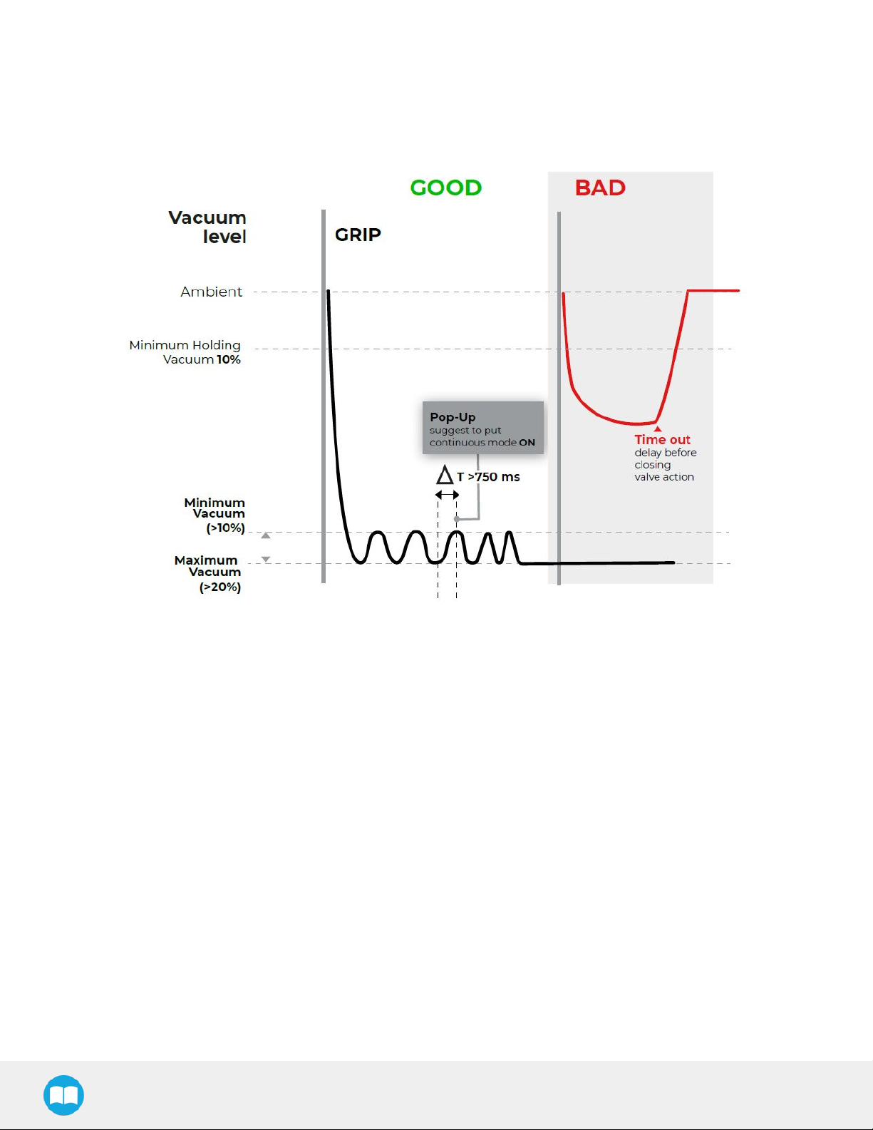
Page 39

39
Fig. 4-2:Vacuumlevel vstimein theautomaticmode
Advanced mode
Theadvanced mode isselected when rMOD==0b01.Inthismode,the usercansetthedesired vacuum levelsand timeout/delay
required to grip/releasetheobject.Behaviorof themanual mode onlydependsonthemaximumvacuumlevel,minimum vacuumlevel
andthetimeout/delayregisters.Thismode should beused when theuserwants to havea constantproductionbehavior.
Whengripping anobject inthemanual mode,withthemaximum vacuumlevel set below 100%,the VacuumGripperwill:
1. Tryto reachthedesired maximumvacuum levelfor amaximumperiod of thedesired timeout value.
2. Ifthe desired maximumvacuum levelisreachedand thevacuumlevel is higherthan20%,objectflag will be set to (gOBJ=0b10).
3. Vacuumgeneratorwill keep thevacuum levelin betweenmin and maxuntila releasecommand isreceived.Objectflag will
toggle in between (gOBJ=0b01)and (gOBJ=0b10).
4. Objectlost/drop flag will be set if thevacuum leveldrops below 10%or if thevacuum levelfalls below thedesired minimum
vacuumlevelformorethanthedesired timeout value.
Whengripping anobject inthemanual modewith themaximumvacuumlevel set to 100%,theVacuum Gripperwill:
1. Continuouslygeneratea vacuum
2. Whentheminimumvacuum levelis reached,objectflag willbe set (gOBJ=0b01). Object flag (gOBJ=0b10)will neverbe set
because100%of vacuum levelis impossible to reach.
3. Objectlost/drop flag will be set if thevacuum leveldrops below 10%or if thevacuum levelfalls below theminimumvacuumlevel
for morethanthedesired timeout value.
Whenreleasing anobjectin themanual mode,theVacuumGripperwill:
EPick- InstructionManual
Page 40
40
1. Openthe releasevalve.
2. Objectdrop flag willbe set whenthe vacuumlevel fallsbelow0.5%.
3. Releasevalve will be kept open for 1second.
Fig. 4-3:Vacuumlevel vstimein theAdvanced mode
Page 41

41
Fig. 4-4:Vacuumlevel vstimein thecontinuousmode
Very porousmaterial detection
Whenaveryporousmaterialis detected orwhenthesuction wearsout,the VacuumGripperwill detectit and reactaccording to the
grippermode.Whenthiscondition occurs,it isimportant to find the underlying reasonbecause it will makethe vacuumgeneratorstart
andstop veryrapidly.Thiscanlead to a prematurewearof thegripperinternalmechanics.
l Inautomaticmode,no fault willbeset,but thegripperwillcontinuouslyrunthevacuumgenerator untila releasecommand is
received.
l Inadvancedmode,afault flag willbe set (gFLT=0x3)and thegripperwillcontinueto runwiththe desired settings.
Object lost/ drop behavior
Whenanobjectis lost ordropped,thegripperwillset an object flag (gOBJ=0b11). Thismeansthatthe vacuumlevel hasfallenbelow
10%orbelow theminimumdesired vacuum levelfor athedesired timeout value.
Object secured behavior
Assoon asthegrip command isreceived bythegripper:
1. Theunknownobject flag will be set (gOBJ=0b00).
2. Ifthe vacuumlevel reachesthedesired maximum vacuumlevel,theobject secureto maxflag willbeset (gOBJ=0b10).
EPick- InstructionManual
Page 42

42
3. Thevacuumgenerator will stop until thevacuum reachthedesired minimumvacuum level.
4. Theobjectsecured to min flag willbeset (gOBJ=0b01)and thevacuum generator will tryto reachthemaximumvacuum again.
Object not detected behavior
When a grip command is received, the gripper will use the desired timeout value as a maximum period of time to detect an object.
When no object is detected after the timeout value, the timeout flag will be set (gFLT=0x6). To retry the same grip command, the
regulate bit needs to be re-asserted (rGTO=0b0,then rGTO=0b1). If newgripping settings are received (rMOD, rPR, rFR, rSP), thereis
no need to re-assertthe regulatebit.
Object release delay
When the release command is received, the vacuum gripper will open the releasevalve in order to let air enterthe suction cups.Once
the pressure inside the suction cup is equal or greater than the ambient pressure,the gripper will set the no object flag (gOBJ=0b11).
Therobot will then move awayfrom the workpiece. Depending on the suction type, thismotion might create a new vacuum inside the
suction cups.Therefore,theusercanset the distancefor therobot to moveawayfrom theworkpiece.Oncethisdistanceis reached,the
VacuumGripper valvewill close.
Emergency stop behavior
Depending on the robot, the behavior might be different when pushing an emergency stop. If the user wants to ensure a good grip
even in emergency stop, the vacuum gripper must be connected to a supply source that will not drop when pushing the emergency
stop. Aslong asthe gripperissupplied, it willalwaystryto keep the workpiece,evenif thecommunicationis stopped withthe robot.
4.6.Control logic
Fig. 4-5:Example of theVacuumGrippercontrol logicwithassociated registers.
4.7. ModbusRTU communication
TheVacuumGripper canbecontrolled byModbusRTUoverRS485.Thissection isintended to provideguidelinesfor setting up a
Modbusmasterthatwill adequatelycommunicatewiththeGripper.
For ageneralintroduction to ModbusRTUandfor detailsregarding theCRCalgorithm,thereaderisinvitedto read the Modbusover
seriallinespecification andimplementationguide availableat:http://www.modbus.org/docs/Modbus_over_serial_line_V1_02.pdf.
For debugging purposes,thereaderisalsoinvited to download one of manyfreeModbusmastersuch astheCASModbusScanner
from ChipkinAutomation Systemsavailable at:http://www.store.chipkin.com/products/tools/cas-modbus-scanner.
Page 43

Info
ModbusRTUisa communication protocol based on aBig Endianbyteorder.Therefore,the16-bit registeraddressesare
transmitted withthemostsignificantbytefirst.However,thedataport is,inthe caseof Robotiq products,basedon theLittle
Endianbyteorder.Assuch,thedata partsof ModbusRTUmessagesaresent withthe lesssignificant bytefirst.
Tip
ModbusRTUspecificationsand detailscanbe found at www.modbus.org.
4.7.1.Connection setup
Thefollowing table describestheconnection requirementsforcontrolling the Gripperusing the ModbusRTUprotocol.
Proprieties Value
Physical interface RS-485
43
Baud rate 1.2KBpsto 10500KBps;Default:115.2KBps
Data bits 8bits
Parity None,Odd, Even;Default:None
Stop bit 1or2 bit; Default:1bit
OtherModbusfunctions FC3,FC4,FC6,FC16,FC23,
Exception responses 0x03 (IllegalDataValue)
SlaveID 1to 9:Default:9
Robot output/Gripperinput registers 1000to 1007
Robot input/Gripper output registers 2000to 2007
Table4-2:ModbusRTUconnection setup for theVacuum Gripper
EPick- InstructionManual
Page 44

44
4.8.Control over TM
4.8.1.TM Robotscompatibility with RobotiqVacuumGrippers
Hardware Version TM FlowVersion TM GripperComponent RobotiqRS232Converter
HW1,HW2,HW3 1.68andlater VAC_V002_XXX Compatible
4.8.2.Getting Started
1
PowerON the robot
2
Tap thetriple baricon inthe upperleft cornerof thescreen
3
Clickon theLoginicon inthenavigation paneon theleft
Page 45

45
4
Enteryourlogin credentialsand clickonOK
5
Clickon GetControl
EPick- InstructionManual
Page 46

46
6
Clickon thetriplebariconin theupperleft cornerof thescreen and selectProject
7
Clickon theNewProject iconin theupperleft cornerof thescreen
Page 47

47
8
Entera namefor your programand clickon theOKbutton
9
EPick- InstructionManual
Page 48

48
4.8.3.TM Vacuum GripperComponents
Hereisthelist of thecurrent Robotiq Gripper TM Componentsto installon TM Robots:
l GRIPPER_ROBOTIQ_VAC_V002_SET.Component = SETtheVacuumGripper(Advanced mode,VacuumLevels,Timeout)
l GRIPPER_ROBOTIQ_VAC_V002_GRIP.Component = Grip a part(Action)
l GRIPPER_ROBOTIQ_VAC_V002_RELEASE.Component= Releaseapart(Action)
l GRIPPER_ROBOTIQ_VAC_V002_SELECTID.Component= Select theslaveID of thegripperwhenusing a dualgrippersetup
Installation
1
Download theTM Plug & PlaySoftwarePackage compressionfileson theofficialwebsite
2
RenametheUSBstorage device''TMROBOT''.Makesurethedrive format isNTFS.
3
Placethezipped componentfilesinthe USB with thefolder directoryTMROBOT:\TM_Export\TMComponent\ComponentObject\.
4
Insert theUSBstoragedevicein therobot controller
5
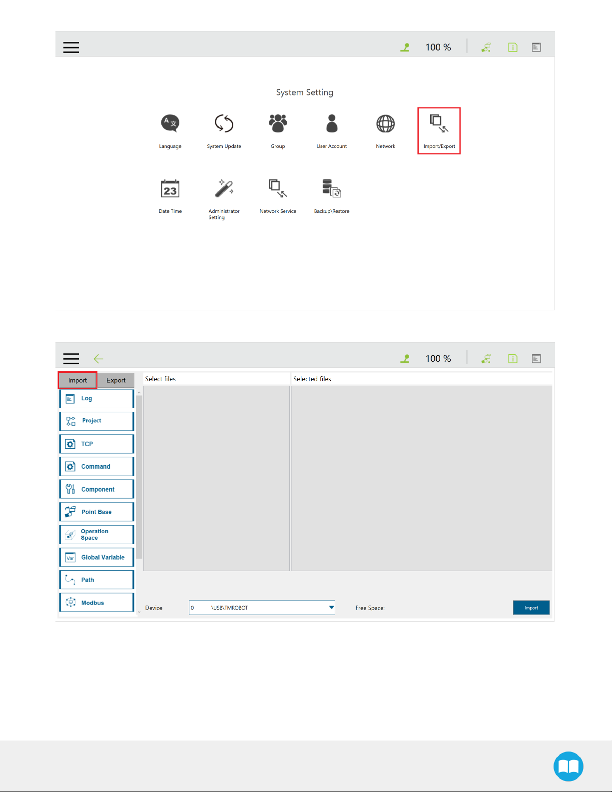
InTM Flow(robot software),tap thetriplebaricon and selectSystem
6
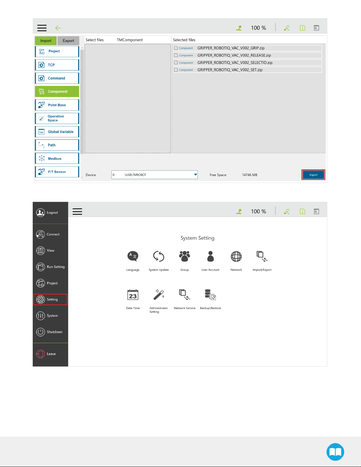
SelectImport/Export
Page 49
49
7
ClicktheImportbutton
8
Clickon TMComponentin theRobot Listwindowand clickon OK
EPick- InstructionManual
Page 50

50
9
Clickon theComponent button of the Import navigation pane
10
Selectthe Componentsyouwantto import and clickon theImportbutton
Page 51
51
11
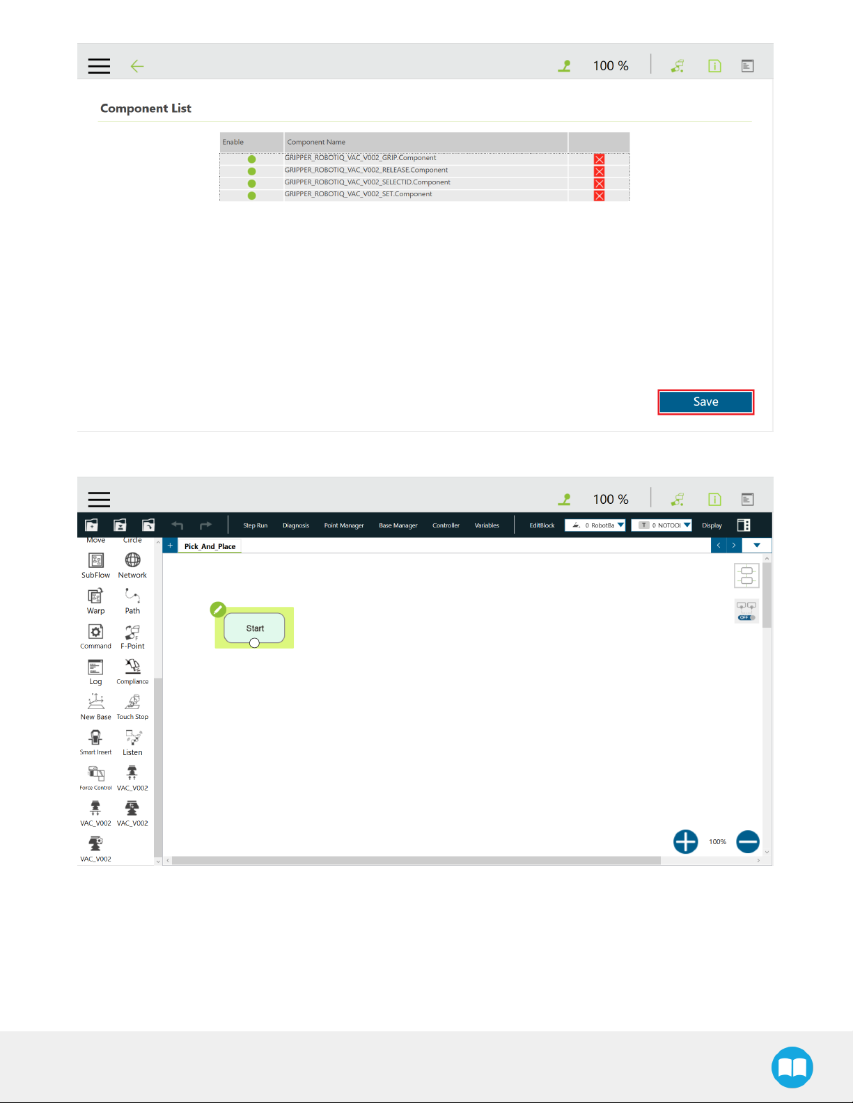
Tap thetriplebariconand select Setting to displaytheRobotSettingwindow
12
Clickon theComponent icon
EPick- InstructionManual
Page 52

52
13
EnablerequiredComponentsinthe Componentslist by ticking theradio buttonbesideeachof them
14
A Component thatis enabled displaysagreenradio button;oncetheComponentsareenabled,clickon theSave button
Page 53
53
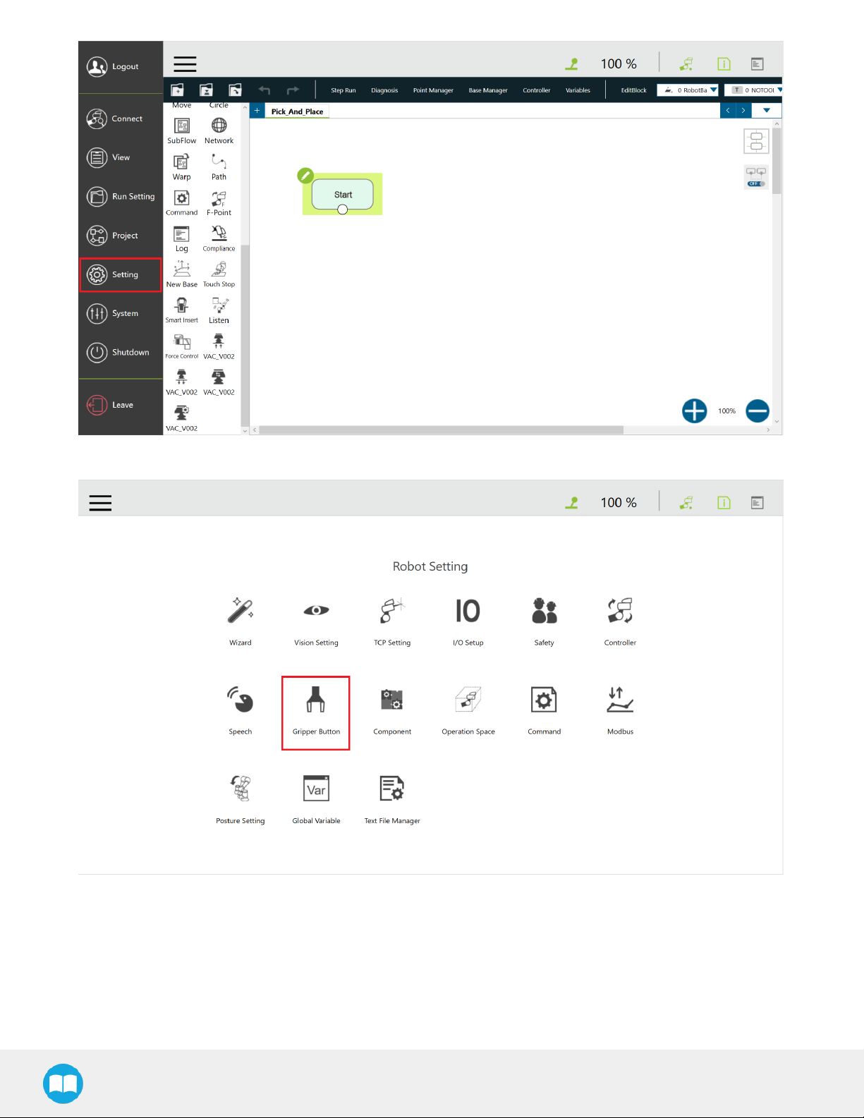
15
Createanewproject or openanexisting project,and locatethe Grippercomponentsinthe navigation pane
GripperButton
Theusercan assignGripperComponentsto the Gripperbutton and usethelatter to open and closethefingersof theRobotiq
Gripper.
1
From theTM Flowhomepage,tap thetriplebariconand select theSettingicon
EPick- InstructionManual
Page 54
54
2
Clickon GripperButton
3
IntheGripperButtonwindow,ticktheUsingCustomizedComponent radio button and select theComponentyou want to assign
to eitherone of the Gripperactions
Page 55

55
4
Inthepop-up window,select or change theComponentyou wishto assignto theGripper action/button,andclickOK
EPick- InstructionManual
Page 56
56
Programming
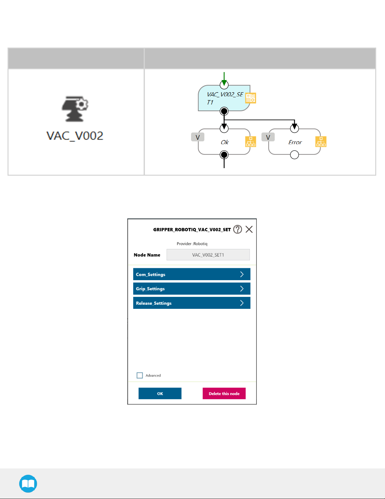
SETComponent
Component Icon Component Node
1
Drag and drop the SETComponent icon afteraprogramGatewayto place a SETprogramnode (VAC_V002_SET1)
2
Tap theSETnode to highlight it and clickon thepencilto edit thesettings
Fig. 4-6:SETNodeSettingsMenu
Page 57

Settings Variable Type Default Description
var_grip_
advanced_
mode
bool False Set to trueto usetheAdvanced mode of thegripper
57
Grip_Settings
Release_
Settings
var_grip_
max_vacuum
var_grip_min_
vacuum
var_grip_
timeout
var_grip_
wait_for_
oject_
detected
var_release_
advanced_
mode
var_release_
shutoff_time
var_release_
wait_for_
object_
released
byte 60
byte 40
int 3000 Timeinmillisecond (ms)until no partis detected
bool True
bool False Set to trueto usetheAdvanced mode of thegripper
int 1000
bool True
Whenset to true,theprogramwillwait for anobjectdetection
Whenset to true,theprogramwillwait for anobjectdetection
20~100whichrepresentsthe vacuumpercentage
10~maxwhichrepresentsthe vacuumpercentage
beforeexiting thecomponent
EPickTimefor thevalveto shut off
beforeexiting thecomponent
var_slave_id int 9 Theslave ID of thegripperusedfor modbuscommunication
var_com_port byte 1 Thenumberof theCOM port on whichthegripper is connected
Table4-3:SETComponent Variables
Advanced Mode
TheAdvanced modeis set to falsebydefault,whichmeansthatthe vacuumvaluesand the timersaresetautomatically.Whenthe
Advanced modeis set to true,thegripper will usethe vacuumlevel parametersand thetimerset by theuserto grip and release.
EPick- InstructionManual
Page 58

58
GRIPComponent
Component Icon Component Node
Thegrip componentis used to activatethegrippersuctionand to pickanobject.Thegrip component hasthreepossibleexits:
1. Detected:Whenan object isdetected bythegripper
2. Not Detected:Whenno object is detectedbythe gripper
3. Error:Whenagripper erroroccurs
1
Drag and drop the GRIPComponent icon aftera programGatewayto placea GRIPprogramnode(VAC_V002_GRIP1)
2
Tap theGRIPnode to highlight it and clickon thepencilto edit thesettings
RELEASEComponent
Component Icon Component Node
TheReleasecomponentisusedto releasethepart byopening a valve.TheRelease componenthastwo possibleexits:
1. Ok:theobjecthasbeenreleased
2. Error:communication error
Page 59

1
Drag and drop the RELEASEComponent icon aftera programGatewayto placea RELEASEprogramnode (VAC_V002_GRIP1)
2
Tap theRELEASEnode to highlight it and clickon thepencil to edit thesettings
SelectIDComponent
TheSelectID component isused to change theSlaveID for themodbuscommunication whenusing adualgripper setup.
Component Icon ComponentNode
59
Info
Usethe Robotiq UserInterfaceto change theModbusSlaveIDAddressof the second VacuumGripperwhen using a dual
gripper(Default = 9).
Changing the ModbusSlave ID
Theusercan change theModbusSlaveID of a Robotiq VacuumGripperviatheRobotiq UserInterface.
Installer
Browseto the support pageof theGripperintheSoftwaresection to download theRUIinstaller (.exe).
1
First,clickon theModbusRTUParameterstab
EPick- InstructionManual
Page 60

60
2
Changethe SlaveID of theVacuumGripperby typing inthe corresponding box
3
Clickon theApplybutton
4
Performa powercycle(24V)whiletheUSBdeviceremainsconnected
Page 61

61
EPick- InstructionManual
Page 62

5.UserInterface
Visit support.robotiq.com to get thelatestinstaller of the Robotiq UserInterfacealong withappropriate documentation.
Seetheinstructionmanual of theRobotiq UserInterfaceformoredetails.
62
EPick- InstructionManual
Page 63

6.Specifications
Caution
Thismanualusesthemetricsystem,unlessspecified, alldimensionsareinmillimeters.
Thefollowing subsectionsprovide data on thevariousspecificationsfor theRobotiq EPickGripper.
l Section 6.1liststhetechnicaldimensionsof theGripper
l Dimensionsfor custom (blank)coupling
l Dimensionsof all available couplings
l Section 6.2presentsthemechanical specificationsof theGripper.
l Section 6.3giveselectrical specificationsforthe Gripper.
63
EPick- InstructionManual
Page 64

64
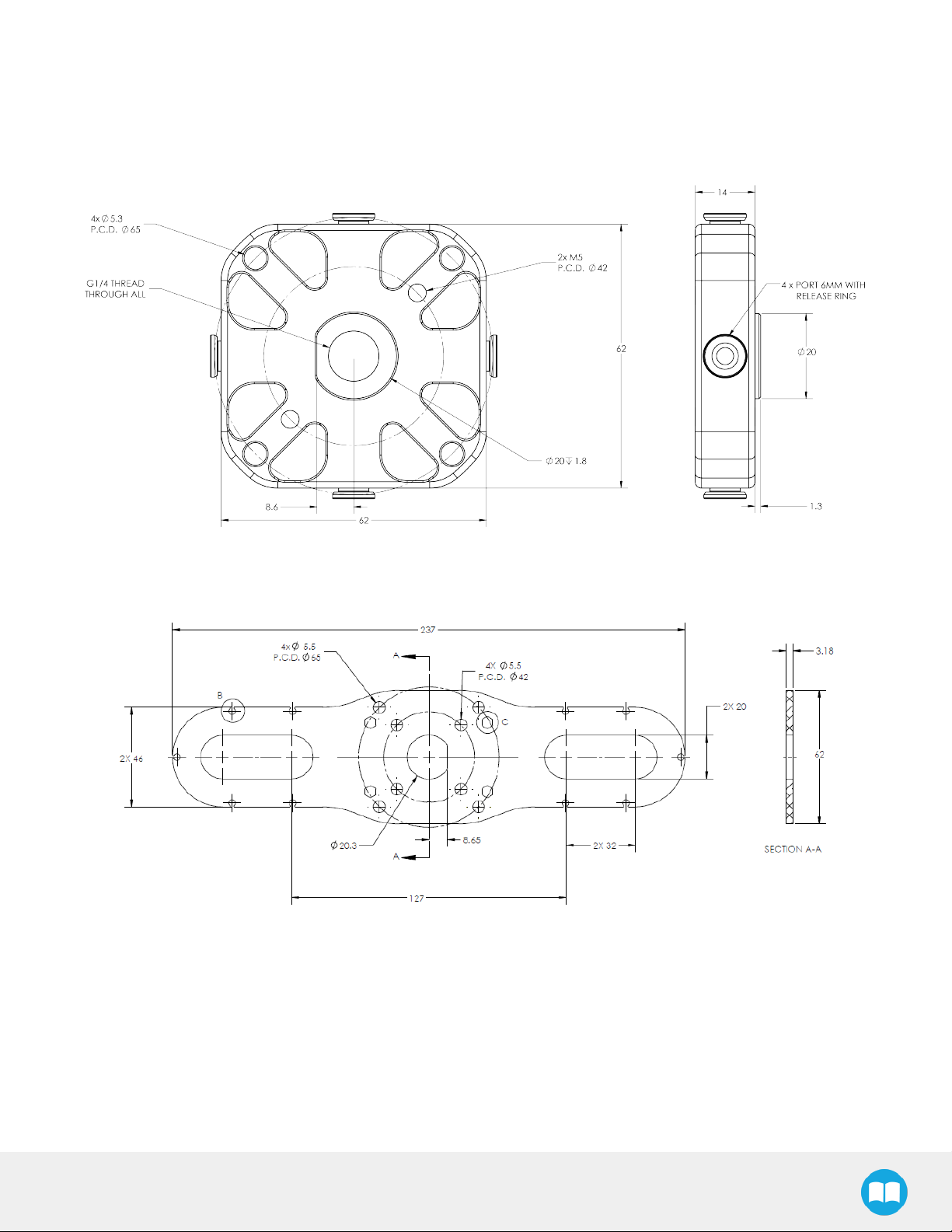
6.1. Technical dimensions
6.1.1.Gripper
ThefigurebelowrepresentstheGripper’sdimensions.
Fig. 6-1:EPickgeneral dimensions
Page 65
6.1.2.SuctionCupSystem
Thefiguresbelow represent thedimensionsof thecomponents of the suction cup systems.
Manifold
65
Bracket for 2 suctioncups
Fig. 6-2:Manifold general dimensions
EPick- InstructionManual
Page 66

66
Bracket for 4 suctioncups
Fig. 6-3:Two airnodesbracket's dimensions
Fig. 6-4:Fourairnodesbracket's dimensions
Page 67

67
Fig. 6-5:Minimumand maximumarrangement possibilitiesof theairnodesposition.
EPick- InstructionManual
Page 68
68
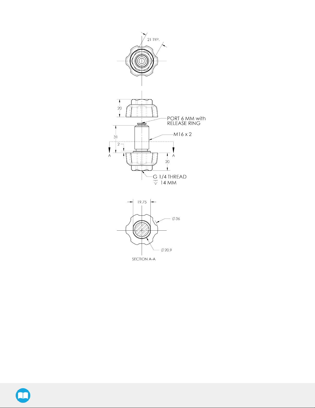
6.1.3.Airnodes
Fig. 6-6:Airnodesdimensions
Page 69
69
6.1.4.Couplings
Operating the VacuumGripperrequiresa coupling provided byRobotiq. Thecoupling ismandatorysinceit integrateselectronicsand
electrical contacts.
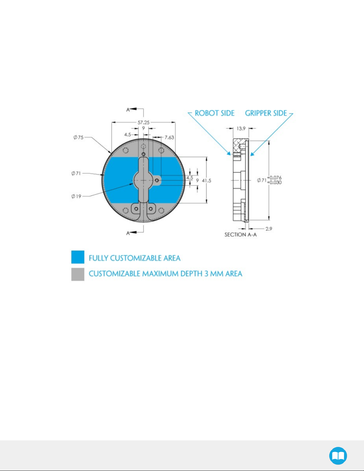
Blank coupling
Below arethe dimensionsof theblankcoupling,AGC-CPL-BLANK-002(referto theSpare Parts,Kitsand Accessoriessection),available
to createa custom bolt pattern.Bluesectioncanbe fullycustomized (holescanbeplaceinanypart of thissection)whilethegrey
section canonlybe worked to a depthof 3 mm.
Fig. 6-7:Workableareadimensionsof blankcoupling AGC-CPL-BLANK-002
EPick- InstructionManual
Page 70

70
CouplingforISO 9409-1-50-4-M6
Bolt patternfor coupling GRP-CPL-062 (referto the SpareParts, KitsandAccessoriessection)iscompatible with:
l 50mm pitchcirclediameter:
l (4)M6-1.0lowhead socket cap screwclearance
l (1)M6indexing pin
l ISO 9409-1standard 50-4-M6
Fig. 6-8:Coupling for ISO 9409-1-50-4-M6.
Page 71

6.2.Mechanicalspecifications
Specifications
71
EPickVacuumGripper
MetricUnits ImperialUnits
Energy source
Grippermass(including coupling)
720g 1.58lbs
Electricity
Maximumvacuum level 80 %
Maximummeanflow 12L/min 3.17gal/min
Payload range
Gripping time
Releasetime
1 0-10kg 0-22lbs
2 150ms
2 180ms
Noiselevel 64dBa
Maximumtorquepermissiblebycustom suction cup
bracket
1
The payload range isfor anon-porous surface with four suction cups of 55mm diameter at 80%of vacuum level.
2
The Gripping and Release time is the time for one suction cup of 40mm and can vary according to the suction cups configuration and
vacuum level.
150Nm / 110lbf-ft
Table6-1:Specificationsof the EPickGripper
Info
All specificationsaremeasuredwith coupling GRP-CPL-062.
EPick- InstructionManual
Page 72
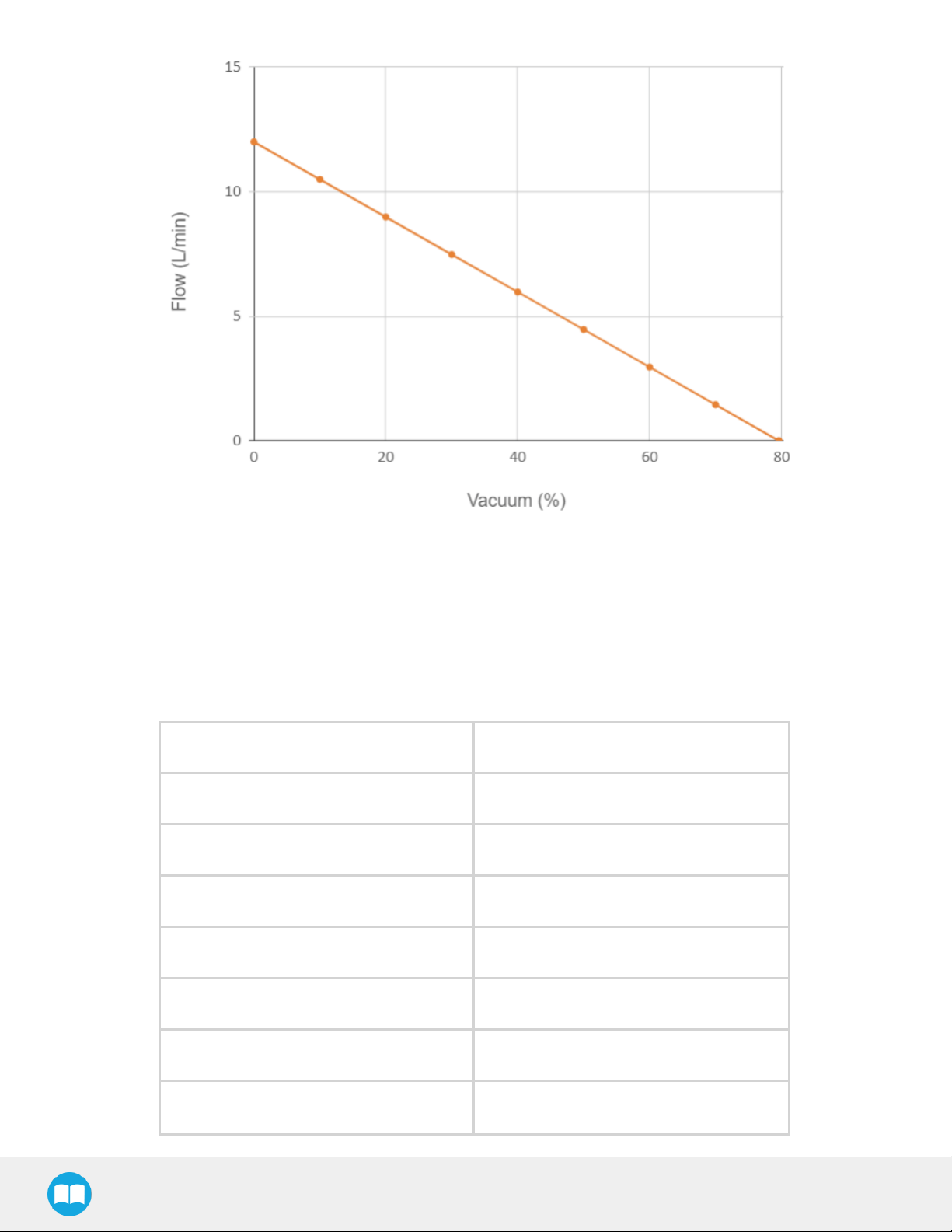
72
Chart6-2:Flow(L/min)vsVacuum(%)
6.2.1.Payloadandforce
Whena load is to be picked by a Vacuum Gripper,several factorshave to be considered. One of themis the vacuum level percentage
selected. This value represents the pressure difference between the inside of the system and the ambient pressure. This table is valid
for anominal atmosphericpressureof 101,3kPa.
Vacuumlevel(%) Pressuredifference(kPa)
0 0
10 10.1
20 20.3
30 30.4
40 40.5
50 50.7
60 60.8
Page 73

70 70.9
80 81.1
90 91.2
100 101.3
Table6-3:Conversionof absolutepressureto vacuumlevel
73
EPick- InstructionManual
Page 74

74
Fig. 6-9:Suction cup withinsidediameter
Depending on theselected suctioncup,the maximumgrip strength can be determined withthefollowing equation:
Where:
l A= Suction cups internal surface(mm
l P= Vacuum Level (kPa)
l n= Quantity of suction cups to lift-off
2
)
For moredetails,pleasereferto the specificationsprovided bythe suctioncup manufacturer.
Thepayload isthemassto belifted according to an acceleration and an applied safetyfactor.Therearethreemaintypesof load
application thatarerepresented in thefollowing cases.Note thatthearrowsrepresent therobot movement.
Case#1 Case#2 Case #3
Where:
Page 75

l M = mass(kg)
75
l G= gravitational acceleration (m/s
l A = robot acceleration(m/s
l µ= friction coefficient
l S= safety factor
2
)
2
)
Themaximumgrip strength of the suctioncup must alwaysbebiggerthanthepayload (Fp> Fc)to guaranteethe good grip of the
piece.Robotiq recommends a minimum securityfactor of 2in everycase.However,afactor4 isrecommended for thenext situations:
l Lowfriction coefficient
l Importantrobot acceleration
l Non-uniform surface
l Poroussurface
l Unequaldistribution of the payload inregardsto thesuction cups
Twocategoriesof materialcanbe lifted bythevacuumgripper:porousand non-porous.A non-porousmaterial isdefined asamaterial
whereairleakagesarenegligible and whereit is possibleto preciselyattaina vacuumpercentage between 10 and 80%.
Example 1: Non-porousmaterial
Fig. 6-10:Non-porousmaterial
Initialdata:
l Material type:non-porous
l Application type:Case#2
l Suction cup diameter(d):40mm (r=20mm)
l Percentage of vacuum:60%(whichisequivalentto 60.8kPa,according to the conversiontableabove)
l Mass:2 kg
l Acceleration:1.2m/s
l n= 4
2
EPick- InstructionManual
Page 76

76
Case #2
l m = 2 kg
l g = 9.81m/s
l a= 1.2m/s
l S= 4 (recommended)
l µ= 0.5
2
2
ValidationthatFp> Fc:305.6N > 97.7N
Since305.6N > 97.7N ,theruleisrespected and wecanensurethe good grip of thepart.
Example 2: Porousmaterial
For porousmaterial,non-negligibleairleakagescanbe observed.Therefore,the useof theEPickis not recommended.Considering
that,theVacuum Gripperwill workin acontinuousmodeto compensate leakagesand thereached vacuum willdepend on 4main
factors:
1. Pump flowrate
2. Themodelof suction cups
3. Porosityof materials
4. Payload to lift
Page 77

Fig. 6-11:Porousmaterial
77
Info
Robotiq recommendsto do someteststo determinethemaximumgrip strength of the suctioncup,depending on the
selected material to lift.It isnot recommended to operatetherobot withvacuum levelslowerthan10%.
EPick- InstructionManual
Page 78

78
Initialdata:
l Material type:porous
l Application type:Case#1
Case #1
l m = 0.2Kg
l g = 9.81m/s
l a= 1.2m/s
l S= 4 (recommended)
2
2
A test hasbeenmade with thismaterialand it wasstatisticallypossible(without anyacceleration)to picka massof 1 kg.
Since,Fp>Fc(9.81N > 8.8N),it ispossibleto lift a massof 0.2kg,asrequired.
Page 79

6.2.2.Centerofmassandtoolcenterpoint
Couplingsareincluded inthecalculationswhenVacuumGrippersarenot mounted onthe Robotiq Wrist Camera.DualGripper
adapterplatesareincluded where appropriate
79
Fig. 6-12:Centerof massand tool centerpoint matrix.
Thecoordinatesystemused to calculate themoment of inertia and centerof massof theVacuum Gripperis shownin thefigurebelow.
Fig. 6-13:Inertiamatrixfor EPickGripper.
EPick- InstructionManual
Page 80

80
6.2.3.Moment Limitation
TheVacuumGripper hasa maximummoment.Thelisted momentis independent to theforceapplied bythe Gripperitself on it's
payload.Forpayload calculation,referto theMechanical specificationssection.
Warning
Thefollowing limitsmustberespected at all time.Calculationof maximum momentshould include therobot acceleration
anda safety factor.
Parameters MaximumValue
Total moment 150Nm
Table6-4:Momentlimitation of the VacuumGripper
6.3. Electricalspecifications
SPECIFICATION VALUE
Operating supply voltage 24VDC± 10%
Quiescent power(minimum
powerconsumption)
Peakcurrent 1.8A for 80 mswhenvacuum pump starts
Table6-5:VacuumGripperelectrical specifications
1W
Page 81

7.Maintenance
TheVacuumGripper onlyrequiresexternal maintenancewithlimited downtime.
Maintenanceisrequired afterspecified usage,measured incycles(workpiecepick-upand release)orusetime (hours).
Following themaintenanceintervalwillensure:
l Correctfunctioning of theVacuum Gripper.
l Validityof thewarranty.
l Properlifetime of theVacuum Gripper.
Warning
Unlessspecified,anyrepairsdoneonthe VacuumGripperwill be done byRobotiq.
Operation Daily Monthly 1M cyclesor
1000hours
81
GripperCleaning Dirty
conditions
Normal
conditions
Periodic Inspection X
Table7-1:VacuumGrippermaintenanceintervals
Caution
Maintenanceoperationsare for theaveragenormalusage of theVacuumGripper,themaintenanceintervalsmust be
adjusted according to theenvironmentalconditionssuchas:
l Operating temperature
l Humidity
l Presenceof chemical(s)
l Presenceof physical objects (debris,scraps,dust,greaseetc.)
l Interaction withoperated parts(sharp orrough)
l Dynamicsof the operation(accelerations)
EPick- InstructionManual
Page 82

82
7.1. Vacuum Grippercleaning
Maintenance Interval Toolsyouneed Partsyouneed
l 4mm hexkey
Monthly
(or dailyin dirtyoperating conditions)
l Drytissueortowel
l Mediumstrengththread locker
l Retaining ring plier
Replacement filter
(if required)
Table7-2:VacuumGrippercleaning intervals
Caution
TheEPickVacuumGripperisnot waterproof orwaterresistant without additionalprotection,onlycleantheGripper with a
dry towel.
Caution
Alwaysturnoff therobot,theVacuum Gripperpowersupplybefore performing anymaintenanceoperation on it.
Caution
Maintenanceoperatormustbegrounded to preventelectrostaticdischarge thatcould damagetheVacuumGripper
electronics.
Caution
Do not usecompressed air to cleanthe VacuumGripper.Doing socanresultin adamageto thecheckvalveor therelease
valve.
1. RemovetheVacuumGripperfrom its coupling using the4 mmhexkeyto unscrewthe four(4)M5-0.8x25 mm socket head cap
screws.Note thateachscrewusesatooth lockwasher,do not discard.
2. CleantheVacuumGripperwitha drytowel,removeall debris,dirt anddustfrom itssurface.Cleanall suction cups.Drythoroughly.Inspect theinput filterto determineif it needsto be changed or not.
3. Ifthe inputfilterneedsto be changed,follow thesteps:
i. Removetheretaining ring.
ii. Removetheold input filter.
iii. Install thenewoneand put backtheretaining ring.
Page 83
Tip
Ifthe inputfilterneedsto be changed,werecommend you to get aretaining ring plierfor internalretaining ringsof 0.038'' tip
diameterto help youreplaceit.
83
Fig. 7-1:EPickinput filterchange
4. Cleanthecoupling withadrytowel andpayaparticularattention to the electricalcontact.
5. Visuallyinspect theVacuum Gripperand payattention to anyvisible damage.
6. Put thecoupling backonand secureusing the four (4)M5-0.8x 25 mmsocket head cap screws.Usethetooth lockwashers.
Applymedium strength thread lockerto theM5 screws.
Whencleaning the VacuumGripperverifythewearof thesuction cup. Ifwearis visible,changethe suctioncup.Pleasereferto the
Spare Parts,Kitsand Accessoriessection to orderEPick replacement parts.
7.2. Periodicinspection
Maintenance Interval ToolsYouNeed PartsYouNeed
l Flat head precision2 mmscrewdriver
Monthly
l Drytissueortowel
l Mediumstrengththread locker
None(unlessdamageis detected)
Info
Table7-3:EPickGripperinspection intervals.
EPick- InstructionManual
Page 84

84
Alwaysturnoff therobot and theVacuum Gripperpowersupply beforeperforming anymaintenance operations.
1. Removeand clean theVacuumGripperfollowing instructionsin theVacuumGrippercleaning section.
2. Inspect theVacuum Gripper:
a. Checkfor anycollision damage.If damage isvisible,contactsupport@robotiq.com.
b. Checkfor anysign of wearon theVacuum Gripperchassis.If wearispresentand mayaffect theVacuumGripper,con-
tactsupport@robotiq.com.
3. Put theVacuum Gripperbackin placeaccording to the instructionsfrom theVacuumGrippercleaning section.
Suctioncupsand airnodes
Depending on yoursetup, mountthe appropriatenumberof vacuumcups to theirmating airbolts.If you need more information about
thesuction cups installation,pleasereferto Suctioncup systemsection.
Warning
Anyunused manifold port should be covered with aprovided port plug to avoid airleakage.
Page 85

8.Spare Parts, Kitsand Accessories
Info
Thefollowing listis up to dateat print timeand issubject to change,checkonlineforupdates.
Info
Unlessspecified,screws,dowelpinsand otherhardwareareincluded onlyfortheGripperside,neverfortherobot side.
Spareparts,kitsand accessorieslist:
85
Item Description Ordering
Number
(1Cup)
Kit for TM Robot EPickKitfor TM VAC-TM-
EPICK-KIT1
Kit for Omron-TM EPickKitfor Omron-TM VAC-
OMRON-
EPICK-KIT1
Kit 2 Suction Cup
System
Kit 4 Suction Cup
System
Suction cup
configurationScrewing Kit
Kit 4 Suction Cup System-2 SuctionCups VAC-SCS-KIT2
Kit 4 Suction Cup System-4 SuctionCups VAC-SCS-KIT4
Suction cup configuration- Screwing Kit VAC-SCS-SCREW-KIT
Ordering
Number
(2Cups)
VAC-TM-
EPICK-KIT2
VAC-OMRON-
EPICK-KIT2
Ordering
Number
(4Cups)
VAC-TM-EPICK-
KIT4
VAC-OMRON-
EPICK-KIT4
VacuumSuction
Cup platefor 2
cups
VacuumSuction
Cup platefor 4
cups
VacuumSuction Cup platefor 2cups VAC-SCS-PLATE-2
VacuumSuction Cup platefor 4cups VAC-SCS-PLATE-4
EPick- InstructionManual
Page 86

86
Item Description Ordering
Number
(1Cup)
Airnode Plug and
Play
VacuumCup 1.5
Bellow 40 mm
VacuumCup 1.5
Bellow 55mm
Replacement filter Filterfor vacuumgenerator VAC-SCS-FILTER
ISO 9409-1-50-4M6coupling
(coupling to
controller)
Airnode Plug andPlay VAC-SCS-NODE
VacuumCup 1.5Bellow 40mm VAC-SCS-CUP40-2
VacuumCup 1.5Bellow 55mm VAC-SCS-CUP55-2
ISO 9409-1-50-4-M6coupling for 2-FingerRobot
Grippers,withscrewsfor Gripperfixation and 1 m
pigtail cable
Ordering
Number
(2Cups)
GRP-CPL-062
Ordering
Number
(4Cups)
ISO 9409-1-31.5-4M5coupling
ISO 9409-1-40-4M6coupling
56-8M4-1D4
coupling
56-6M4-1D6
coupling
60-4Ø5-1D5
coupling
63-6M6-2D6
coupling
ISO 9409-1-31.5-4-M5coupling for Adaptive
Robot Gripper2-Finger,with screwsfor Gripper
fixationand 1m pigtail cable
ISO 9409-1-40-4-M6coupling for AdaptiveRobot
GripperGripper 2-Finger,withscrewsfor Gripper
fixationand 1m pigtail cable
Coupling for56mm PCD1with(8)M4and (1)4
mmindexing pin,withscrewsfor 2-FGripper
fixationand 1m pigtail cable
Coupling for56mm PCD1with(6)M4and (1)6
mmindexing pin,withscrewsfor 2-FGripper
fixationand 1m pigtail cable
Coupling for60mm PCD1with(4)M5thread and
(1)5mm indexing pin,with screwsfor 2-FGripper
fixationand 1m pigtail cable
Coupling for63mm PCD1with(6)M6and (2)
6mmindexing pins,with screwsfor 2-FGripper
fixationand 1m pigtail cable
GRP-CPL-063
GRP-CPL-064
AGC-CPL-065-002
AGC-CPL-066-002
AGC-CPL-067-002
AGC-CPL-068-002
40-4M5-1D3
coupling
Coupling for40mm PCD1with(4)M5and (1)
3mmindexing pins,with screwsfor 2-FGripper
fixationand 1m pigtail cable
AGC-CPL-070-002
Page 87

87
Item Description Ordering
31.5-4M4
coupling
Adapterplateto
63-4M6-71-2D3
Adapterplateto
63-4M6-61_4-2D6
Adapterplateto
80-6M8-2D82D8
Coupling for31.5mm PCD1with(4)M4,with
screwsfor 2-FGripperfixationand 1 m
pigtail cable
Wristadapterplatefor usewithAGC-CPL-064-
002.Interfaceto 63 mmPCD1with(4)M6screws
and71 mm PCD1with(2)M3indexing pins
Wristadapterplatefor usewithAGC-CPL-064-
002.Interfaceto 63 mmPCD1with(4)M6screws
and61.4mm PCD 1with (2)M6 indexing pins
Wristadapterplatefor usewithAGC-CPL-064-
002.Interfaceto 80 mmPCD1with(6)M8screws
and(2)M8 indexing pins
Number
(1Cup)
Ordering
Number
(2Cups)
AGC-CPL-071-002
AGC-APL-151-002
AGC-APL-152-002
AGC-APL-153-002
Ordering
Number
(4Cups)
EPick- InstructionManual
Page 88

9.Troubleshooting
9.1. VacuumGripperverification
Ifyou arenot ableto attainthe desired vacuumlevelor if adiminutionof the vacuumlevel occurs,verify:
l Thesuction cupsstatus
l That theairpath is cleanand not obstructed (including themanifold)
l Ifa filtercleaning isnecessary
88
EPick- InstructionManual
Page 89

10. Warranty
Robotiq warrantstheEPickGripperagainst defectsinmaterial andworkmanship fora period of one yearfrom thedateof reception
whenutilizedasintended.Robotiq also warrantsthat thisequipmentwill meet applicable specificationsundernormal use.
Warning
Warrantyappliesunder thefollowing conditions:
l Usagerespectstheoperating and storageconditionsspecified in Environmentaland OperatingConditionssection.
l Properinstallation of theVacuumGripperspecified in Installationsectionand thefollowingsubsections.
l Until one of these conditionis reached:
o
1year
89
o
2000000cycle count
l Usagerespectsmaintenancespecified inthe Maintenance section.
l Usagerespectsrecommended payload and forcespecified inthe Mechanicalspecificationssection.
1
Cyclecount:One(1)cycleisdefined asa successfulobjectgripping attempt. It iscalculated in theinternalmemoryof theEPick
1
Gripperand canbe seenon therobot teachpendantwhen using with theRobotiq UserInterface.
Duringthewarrantyperiod,Robotiq will repairor replaceanydefectiveEPickGripper,aswellasverify and adjustthe VacuumGripper
freeof charge if theequipment should need to be repaired or if theoriginaladjustment iserroneous.If theequipment issent backfor
verificationduringthewarrantyperiod and found to meet allpublished specifications,Robotiq willcharge standard verificationfees.
Theunitisconsidered defectivewhenat least oneof thefollowing conditionsoccurs:
l TheVacuumGripper feedbacknecessaryfor therobot program isnot accessible.
l Wearof theVacuumGrippercomponents dueto directcontactwiththeworkpieceor obstaclesisnot covered bythe warranty.
Caution
Thewarrantywillbecomenulland void if the:
l Unit hasbeentampered with,repaired orworked onbyunauthorized individuals.
l Screws,otherthanasexplained inthisguide,havebeenremoved.
l Unit hasbeenopenedotherthanasexplained in thisguide.
l Unit serialnumberhasbeenaltered, erased,orremoved.
l Unit hasbeenmisused,neglected,or damaged by accident.
Thiswarrantyisin lieuof all otherwarrantiesexpressed, implied, orstatutory,including,but not limited to,the implied warrantiesof
merchantabilityand fitnessfor aparticularpurpose.Inno event shall Robotiq be liablefor special,incidental,or consequential
damages.
Robotiq shall not be liable for damagesresulting from theuseof the EPickGripper,norshall Robotiq be responsible foranyfailurein
theperformanceof otheritemsto whichtheEPickGripperisconnected or theoperationof anysystem of whichtheVacuumGripper
maybe a part.
EPick- InstructionManual
Page 90

90
Exclusions
Thiswarrantyexcludesfailureresulting from: improperuseor installation,normalwearand tear,accident,abuse,neglect,fire,water,
lightning or otheractsof nature,causesexternal to the VacuumGripperor otherfactorsbeyond Robotiq's control.
Robotiq reservestheright to makechangesinthe designorconstruction of anyof its productsatanytime without incurring any
obligation to makeanychangeswhatsoeveron unitsalreadypurchased.
Page 91

11.Harmonized Standards, Declarationsand Certificates
11.1. Original ECdeclarationof incorporation
91
EPick- InstructionManual
Page 92

92
11.2.Applied standards
Thissection describesallapplied harmonized standardsfor thedesign and production of the EPickVacuumGripper.Conformityof the
product is only met if all instructions of the current user manual arefollowed. Among others;proper installation, safety measures and
normalusage must be respected. A riskassessment specific to theuser'sfinalapplication must also be carried out.
Caution
Conformityof theproduct isonlymetif all instructionsof thefollowing manualarefollowed.Among others;installation,
safetymeasureand normalusagemustberespected.
Thefollowing standardshavebeenapplied:
ISO 12100 2010 Safetyof machinery—Generalprinciplesfor design— Riskassessment and riskreduction
ISO 9409-1 2004 Manipulating industrialrobots– Mechanical interfaces– Part1:Plates
ISO 4414 2010 Pneumaticfluid power–General rulesand safetyrequirements for systemsand theircomponents
IEC 61000-6-2 2016 Genericstandards–Immunitystandardfor industrialenvironments
IEC 61000-6-4 2018 Genericstandards– Emission standard forindustrialenvironments
EN 50581 2012
Technicaldocumentation for theassessment of electrical andelectronicproductswithrespectto
therestriction of hazardoussubstances
Page 93

12.Contact
www.robotiq.com
Contact Us
Phone
1-888-ROBOTIQ (762-6847)
(01)418-380-2788OutsideUSandCanada
Fax
1-418-800-0046
Technicalsupport andengineering
option 3
Sales
option 2
93
Headoffice
Robotiq:
966,cheminOlivier
Suite 500
St-Nicolas,Québec
G7A2N1
Canada
Whereautomation Proscometo sharetheirknow-howand get answers.
dof.robotiq.com
EPick- InstructionManual
 Loading...