

Page 1
Robotiq 2F-85 & 2F-140
for TM Robots
Original Notice
© 2018 Robotic Inc.
Instruction Manual
robotiq.com | leanrobotics.org
Page 2

Revisions 5
1. General Presentation 7
1.1. Gripper nomenclature 8
1.2. 2F-85 vs. 2F-140 9
1.3. Object picking 10
1.4. Setup and control 13
2. Safety 14
2.1. Warning 15
2.1.1. Risk assessment and final application: 15
2.2. Intended Use 16
3. Installation 17
3.1. Scope of Delivery 18
2
3.1.1. TM Kit 18
3.2. Required Tools and Equipment 18
3.3. Environmental and Operating Conditions 19
3.4. Mechanical Installation 19
3.4.1. Installing fingers on the Gripper 19
3.4.2. Installing the fingertips on the Gripper 21
3.4.3. Installing a Protector Kit on the Gripper Fingers 22
3.4.4. Installing the Gripper onto the robot 22
Single Gripper 22
Multiple Grippers 23
3.5. Electrical Setup 24
3.5.1. Pinout Interface 26
3.5.2. Coupling to controller 26
Single Gripper 28
Multiple Grippers 28
4. Control 30
4.1. Overview 30
4.2. Gripper Register Mapping 32
4.3. Robot Output Registers &Functionalities 33
4.4. Robot Input Registers &Status 36
2F-85 &2F-140 - Instruction Manual
Page 3

3
4.5. Picking Features 39
4.5.1. Force control 39
4.5.2. Re-Grasp 44
4.5.3. Object detection 45
4.6. Control Logic 46
4.7. Modbus RTUCommunication 47
4.7.1. Connection Setup 48
4.7.2. Read holding registers (FC03) 49
4.7.3. Read input registers (FC04) 50
4.7.4. Preset multiple registers (FC16) 51
4.7.5. Master read & write multiple registers FC23 52
4.7.6. Modbus RTU example 54
4.8. Control over TM 63
4.8.1. TMRobots Compatibility with Robotiq Grippers 63
4.8.2. Getting Started 63
4.8.3. TMGripper Components 67
Installation 67
Gripper Button 74
Programming 76
SETComponent 76
GRIPComponent 78
RELEASEComponent 79
CHANGEGRIPPERComponent 81
Changing the ModbusSlave ID 83
5. User Interface 85
6. Specifications 86
6.1. Technical dimensions 87
6.1.1. Couplings 91
Blank coupling 91
Coupling for ISO 9409-1-50-4-M6 92
Coupling for ISO 9409-1-31.5-4-M5 93
Coupling for ISO 9409-1-40-4-M6 94
Coupling for PCD 56 with 8 x M4 95
2F-85 &2F-140 - Instruction Manual
Page 4

Coupling for PCD 56 with 6 x M4 96
Coupling for PCD 60 with 4 x M5 97
Coupling for PCD 63 with 6 x M6 98
6.1.2. Fingertips 99
Flat silicone fingertip 100
Grooved fingertip 101
6.2. Mechanical specifications 102
6.2.1. Payload and force 103
Friction grasp and form-fit grasp 105
Maximum payload by grasp type 105
6.2.2. Equilibrium Line 106
6.2.3. Center of mass, tool centere point and moment of inertia 107
6.2.4. Moment and force limits 109
4
6.3. Electrical specifications 110
7. Maintenance 111
7.1. Gripper cleaning 112
7.2. Periodic inspection 114
7.3. Fingertip replacement 115
7.4. Overhaul 116
8. Spare Parts, Kits and Accessories 117
9. Troubleshooting 120
10. Warranty andPatent 121
11. Contact 124
12. Harmonized Standards, Declarations and Certificates 125
12.1. Translation of original EC declaration of incorporation 125
12.2. Applied standards 126
2F-85 &2F-140 - Instruction Manual
Page 5

5
Revisions
Robotiq may modify this product without notice, when necessary, due to product improvements, modifications or changes in
specifications. If such modification is made, the manual will also be revised, see revision information. See the latest version of this
manual online at support.robotiq.com.
Revision 2019/03/13
Updated mechanical specifications (section 6.2)
Revision 2018/12/06
First Publication of Instruction Manual
2F-85 &2F-140 - Instruction Manual
Page 6

6
Copyright
© 2019 Robotiq Inc. All rights reserved.
This manual and the product it describes are protected by the Copyright Act of Canada, by laws of other countries, and by international
treaties, and therefore may not be reproduced in whole or in part, whether for sale or not, without prior written consent from Robotiq.
Under copyright law, copying includes translation into another language or format.
Information provided by Robotiq in this document is believed to be accurate and reliable. However, no responsibility is assumed by
Robotiq for its use. There may be some differences between the manual and the product if the product has been modified after the
edition date.
The information contained in this document is subject to change without notice.
2F-85 &2F-140 - Instruction Manual
Page 7

1. General Presentation
The terms "Gripper", "Adaptive Gripper", "Robotiq Gripper", "Robotiq Adaptive Gripper", "2-Finger 85", "2-Finger 140", "2F-85"
and "2F-140" used in the following manual all refer to the Robotiq 2-Finger Adaptive Robot Gripper.The Robotiq 2-Finger Adaptive
Gripper has two versions, 85 and 140. The 2-Finger version will change finger opening dimensions, which will be 85 mm (2F-85) or
140mm (2F-140).Both versions use the same base, installation and control will be exactly the same. The 2-Finger Gripper is a robotic
peripheral that is designed for industrial applications. Its design makes it a unique robotic end-of-arm tool to quickly pick, place and
handle a large range of objects of varying sizes and shapes.
Info
Unless specified, information in this manual applies to both the 85 and the 140 mm version of the 2-Finger Adaptive Robot
Gripper.
Info
The following manual uses the metric system, unless specified, all dimensions are in millimeters.
Info
7
The following section presents the key features of the grasp-type gripper and must not be considered as appropriate to the
gripper operation, each feature is detailed in the appropriate section of the manual. Safety guidelines must be read and
understood before any operation is attempted with thegrasp-type gripper.
2F-85 &2F-140 - Instruction Manual
Page 8
8
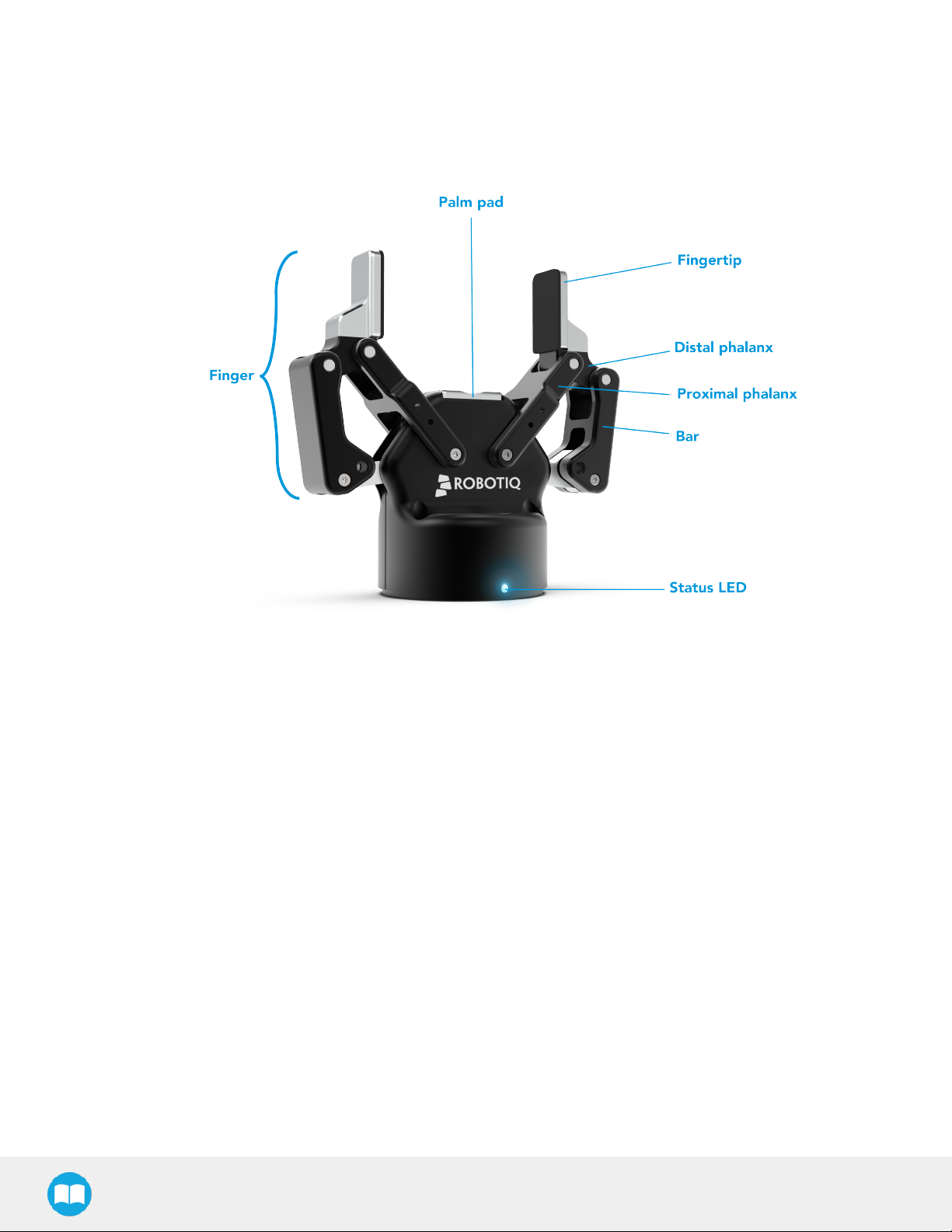
1.1. Gripper nomenclature
The 2-Finger Gripper has two articulated fingers that each have two joints (two phalanxes per finger), as shown in the figure below.The
grasp-type gripper can engage up to five points of contact with an object (two on each of the phalanges plus the palm). The fingers are
under-actuated, meaning they have fewer motors than the total number of joints. This configuration allows the fingers to automatically
adapt to the shape of the object they grasp and it also simplifies the control of the grasp-type gripper.
Fig. 1-1: Robotiq 2-Finger Adaptive Gripper.
Please refer to the for details on standard and optional parts.
2F-85 &2F-140 - Instruction Manual
Page 9
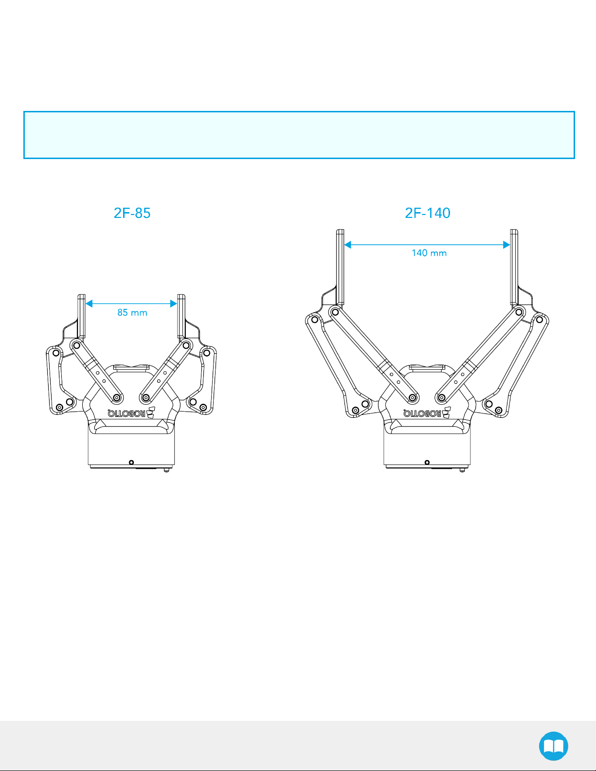
1.2. 2F-85 vs. 2F-140
The 2-Finger Gripper comes with either 85 mm opening (2-Finger 85) or 140 mm opening (2-Finger 140) according to the figure below.
The chassis will remain the same, only the fingers will change. Please refer to the Mechanical Installation section for installation
instructions. Finger kits are available in the Spare Parts and Accessories section.
Info
Details on the 2-Finger 85 and 2-Finger 140 (dimensions and specifications) can be found in the Specifications section.
9
Fig. 1-2: The 2-Finger 85 and 140 mm versions.
2F-85 &2F-140 - Instruction Manual
Page 10
10
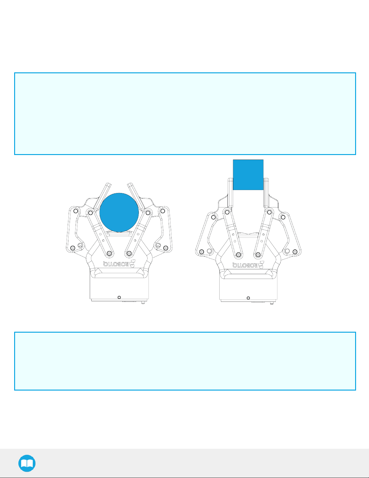
1.3. Object picking
The 2-Finger Gripper has a single actuator for opening and closing the fingers, the fingers automatically adapt to the shape of the
object manipulated.
Fingers will adopt either a parallel grasp or encompassing grasp as shown in the figure below.
Info
Closing or opening is done via the "Go to requested position" command and is input to the Gripper Whether the fingers
close to produce an emcompassing or fingertip grasp is decided at the Gripper level automatically. It will depend on:
l The objects's geometry;
l The relative position of the object with respect to the Gripper.
In other words, picking the same object could result in either an emcompassing or fingertip grasp based on an object's
position and geometry.
Fig. 1-3: 2-Finger parallel and encompassing grips.
Info
It is important to note that a fingertip grasp can only be performed when the fingers touch the object with the upper section
of the distal phalanxes first. Inversely, for an encompassing grip, the fingers must touch the object with the proximal or the
lower section of the distal phalanxes first. Also, to ensure stability, the object should be held against the Gripper palm while
performing an encompassing grip. Refer to the figure below for a visual representation of the parallel and encompassing
grasp regions on the distal phalanx of the 2-Finger Gripper.
2F-85 &2F-140 - Instruction Manual
Page 11
11
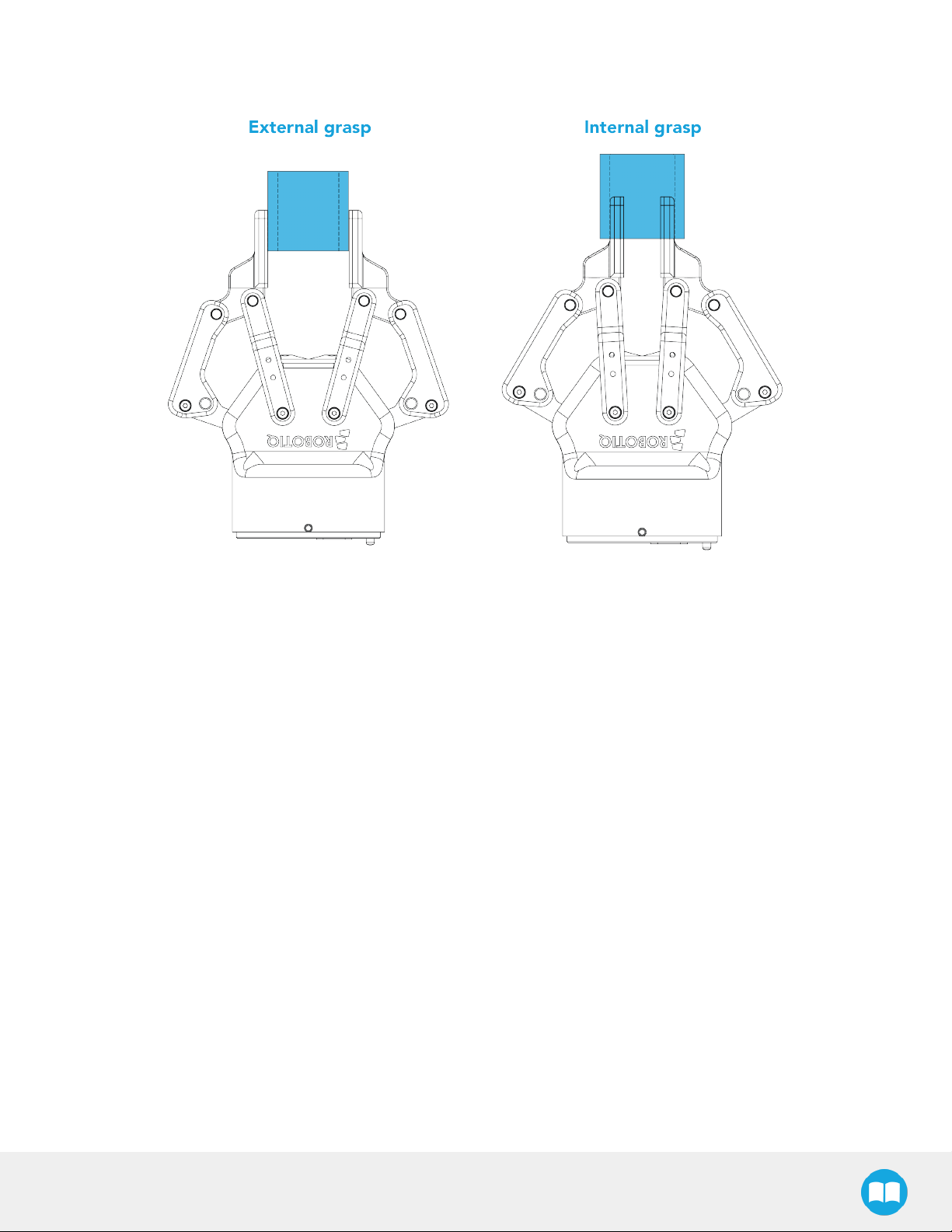
The 2-Finger Adaptive Robot Gripper also allows for internal grasping. The fingers can pick hollow objects from the inside by applying
pressure with the outside of the fingers. Refer to the figure below for a visual representation and to the Picking Features section for
details on the possible position commands of your Gripper.
Fig. 1-4: Finger internal and external grasping.
2F-85 &2F-140 - Instruction Manual
Page 12
12
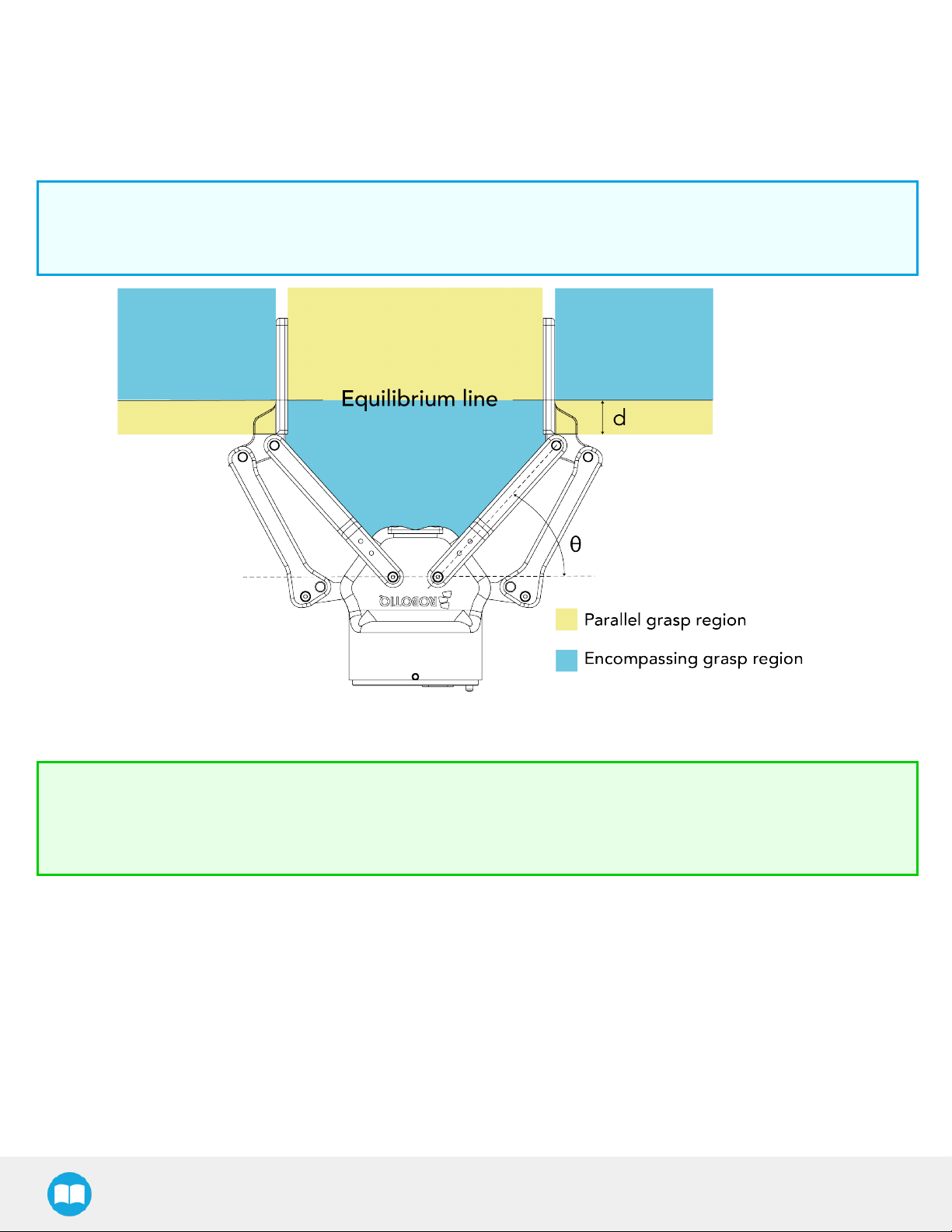
The Gripper equilibrium line is the grasping region that separates the encompassing grasp from the parallel grip. When grasping an
object close enough to the inside (palm) of the Gripper, the encompassing grasp will occur (unless the object size or shape is not
adequate) and the fingers will close around theobject.
If grasped above the equilibrium line, the same object will be picked up in a parallel grasp by the fingertips and the fingers will close
with a parallel motion. The figure below shows the encompassing grasp region, the equilibrium line, and the parallel grasp region on
the2-Finger Adaptive Robot Gripper.
Info
The details of the equilibrium line relation between opening angle and the related position d can be found in the Mechanical
specifications section.
Fig. 1-5: Equilibrium line on the 2-Finger, shown with no fingertip pads.
Tip
Grasping an object that could be grasped by an encompassing grasp (a cylinder for example) on the equilibrium line is not
recommended, as slight variations on the position will switch the grasp from parallel to encompassing and vice versa. Robot
programming should be done so that the grasping mode will be predetermined.
2F-85 &2F-140 - Instruction Manual
Page 13

1.4. Setup and control
The Gripper is powered and controlled directly via a single Device Cable that carries a 24V DC supply and Modbus RTU
communication over RS-485, see Section 3.5 for wiring information and Section 4 for control of the Gripper (various software packages
are available for control via various robotcontrollers).
Info
Robotiq Universal Controller is available when industrial communication protocols are required (other then Modbus RTU
over serial).
Gripper Coupling is required for 2-Finger usage, the Coupling will provide mechanical and electrical connectivity. Please refer to the
Mechanical Installation section for installation of the Coupling,to the Specifications section for technical drawings, and to the Spare
Parts, Kits and Accessories section for available couplings.
The 2-Finger has an embedded object detection feature using indirect sensing methods. When picking an object via the "go to"
command, the Gripper status will allow you to know if an object is picked or not via a simple object detection bit (0 or 1). When an
object is detected, the Gripper will stop. If the object is being dropped, the Gripper will automatically close to keep the object until the
''go to'' command limit is attained. For details on object detection, see Control section.
13
2F-85 &2F-140 - Instruction Manual
Page 14

2. Safety
Warning
The operator must have read and understood all of the instructions in the following manual before handling the Robotiq
2-Finger Adaptive Robot Gripper.
Caution
The term "operator" refers to anyone responsible for any of the following operations on the 2-Finger Adaptive Robot
Gripper:
l Installation
l Control
l Maintenance
l Inspection
l Calibration
14
l Programming
l Decommissioning
This documentation explains the various components of the 2-Finger and general operations regarding the whole life-cycle of the
product from installation to operation and decommissioning.
The drawings and photos in this documentation are representative examples and differences may exist between them and the delivered
product.
2F-85 &2F-140 - Instruction Manual
Page 15

15
2.1. Warning
Caution
Any use of the Gripper in noncompliance of these warnings is inappropriate and may cause injury or damage.
Warning
l The Gripper needs to be properly secured before operating the robot.
l Do not install or operate a Gripper that is damaged or lacking parts.
l Never supply the Gripper with an alternative current source.
l Make sure all cord sets are always secured at both ends, at the Gripper and at the robot.
l Always satisfy the recommended keying for electrical connections.
l Be sure no one is in the robot and/or Gripper path before initializing the robot's routine.
l Always satisfy the Gripper payload.
l Set the Gripper pinch force and speed accordingly, based on your application.
l Keep fingers and clothes away from the Gripper while the power is on.
l Do not use the Gripper on people or animals.
l For welding applications, make sure there are no Gripper parts on the ground path of the welding power source.
Any use of the Gripper in noncompliance of these warnings is inappropriate and may cause injury or damage.
2.1.1. Risk assessment and final application:
The Robotiq 2-Finger Adaptive Gripper is meant to be used on an industrial robot. The robot, Gripper and any other equipment used
in the final application must be evaluated with a risk assessment. It is the robot integrator's duty to ensure that all local safety measures
and regulations are respected. Depending on the application, there may be risks that need additional protection/safety measures, for
example, the work-piece the Gripper is manipulating may be inherently dangerous to the operator.
2F-85 &2F-140 - Instruction Manual
Page 16

16
2.2. Intended Use
The Gripper unit is designed for grasping and temporarily securing or holding objects.
Caution
The Gripper is NOT intended for applying force against objects or surfaces.
The product is intended for installation on a robot or other automated machinery and equipment.
Info
Always comply with local and/or national laws, regulations and directives on automation safety and general machine safety.
The unit may be used only within the range of its technical data. Any other use of the product is deemed improper and unintended use.
Robotiq will not be liable for any damages resulting from any improper or unintended use.
2F-85 &2F-140 - Instruction Manual
Page 17

3. Installation
The following subsections will guide you through the installation and general setup of your Robotiq 2-Finger Adaptive Robot Gripper.
l The Scope of Delivery section
l The Required Tools and Equipment section
l The Environmental and Operating Conditions section
l The Mechanical Installation section
l The Electrical Setup section
Warning
Before installing:
l Read and understand the safety instructions related to the 2-Finger Adaptive Robot Gripper.
l Verify your package according to the Scope of delivery and your order.
17
l Have the required parts, equipment and tools listed in the requirements readily available
Warning
When installing:
l Satisfy the environmental conditions.
l Do not operate the Gripper, or even turn on the power supply, before it is firmly anchored and the danger zone is cleared.
The fingers of the Gripper may move and cause injury or damage.
2F-85 &2F-140 - Instruction Manual
Page 18

18
3.1. Scope of Delivery
3.1.1. TM Kit
Robotiq 2F-85 Adaptive Gripper Robotiq 2F-140 Adaptive Gripper
l 1x 2F-85 Basic Gripper Unit (with Flat Silicone Fingers)
l 1x End Effector Coupling for Bolt Pattern
ISO 9409-1-50-4-M6 (with 1 m Pigtail Cable)
l 1 x 10 m Robotiq Device Cable
l 1x RS485 to RS232 Converter
l 1x Screw Kit for Fixing End Effector Coupling on TM
Robots
l 1x RS485 to USBConverter (for troubleshooting or Slave
Address IDChange on a PC)
l 1x 2F-140 Basic Gripper Unit (with Flat Silicone Fingers)
l 1x End Effector Coupling for Bolt Pattern
ISO 9409-1-50-4-M6 (with 1 m Pigtail Cable)
l 1 x 10 m Robotiq Device Cable
l 1x RS485 to RS232 Converter
l 1x Screw Kit for Fixing End Effector Coupling on TM
Robots
l 1x RS485 to USBConverter (for troubleshooting or Slave
Address IDChange on a PC)
3.2. Required Tools and Equipment
The following tools are required to install the 2-Finger Adaptive Gripper:
l 4 mm hex key to mount the Gripper onto its coupling.
l Metric hex key according to your coupling to mount the coupling onto the robot.
Optional tools if installing finger kits: AGC-FIN-KIT-085 or AGC-FIN-KIT-140:
l 2 mm hex key
Optional tools if installing other fingertips: AGC-TIP-204-085, AGC-TIP-205-085, AGC-TIP-420-140, AGC-TIP-420-140
l 4 mm hex key
The following parts are required for setup :
l Power supply (see below).
l Fuse (if applicable), see information below.
l Emergency stop is not provided, but its use is strongly advised.
The Gripper needs to be supplied by a DC voltage source. This power supply is not included with the Gripper. Required power supply
must match the Robotiq device. The following table shows the specifications with regards to the power supply required to operate the
Gripper and the optional Robotiq Controller.
Table 3-1: 2-Finger power supply requirements.
Info
1
Suggested fuse is a: Phoenix Contact # 0916605 2 A thermal, use AWG #20 wiring.
Warning
2F-85 &2F-140 - Instruction Manual
Page 19

If your power supply could exceed the specified regulation, over-voltage protection is required.
Robotiq recommends the use of the following power supplies:
Tip
Optional Robotiq Universal Controller can use the same power supply.
3.3. Environmental and Operating Conditions
CONDITION VALUE
19
Minimum storage/transit
temperature
Maximum storage/transit
temperature
Minimum operating temperature -10°C [14°F]
Maximum operating temperature 50°C [122°F]
Humidity (non-condensing) 20-80% RH
Vibration < 0.5G
Other
Table 3-2: Environmental and operating conditions of the 2-Finger Adaptive Gripper.
-30°C [-22°F]
60°C [140°F]
l Free from dust, soot or fluids
l Free from corrosive liquids or gases
l Free from explosive liquids or gases
l Free from powerful electromagnetic inter-
ference
3.4. Mechanical Installation
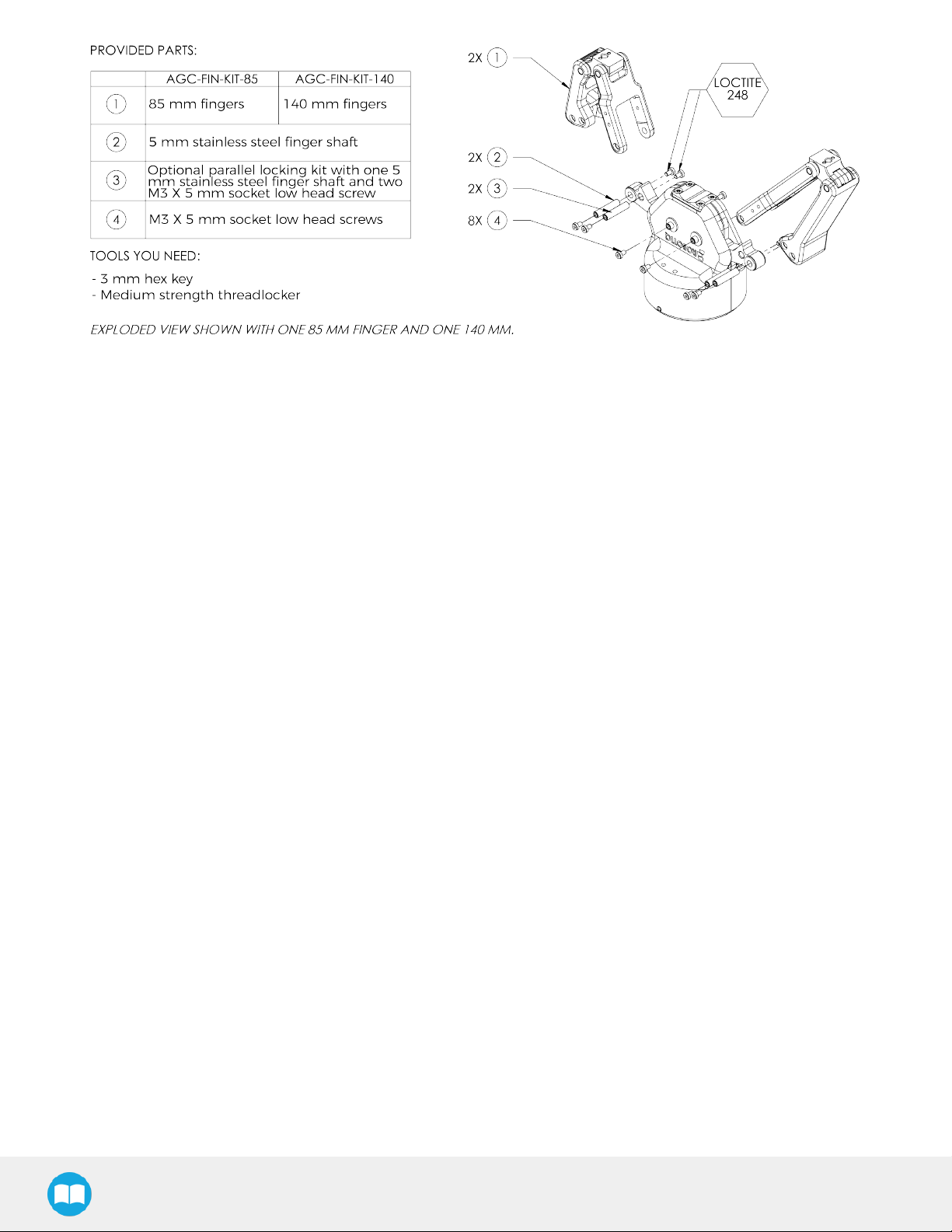
3.4.1. Installing fingers on the Gripper
Depending on your order, you may or may not have fingers already mounted on the Gripper. The first step of installation should be to
install the fingers. Refer to the figure below for finger placement. To do so :
1. Align fingers with chassis axes. To do so, the slot on the finger bar should be aligned correctly with the corresponding chassis
axis.
2. Insert the finger shaft in the finger bar bracket hole and through the chassis axis (top hole is for parallel locking while bottom hole
is for finger installation)..
3. Apply medium strength threadlocker on the provided screws, align the finger bar and fasten to the chassis/chassis axis.
2F-85 &2F-140 - Instruction Manual
Page 20
20
Fig. 3-1: 2-Finger Adaptive Gripper installation.
2F-85 &2F-140 - Instruction Manual
Page 21
21
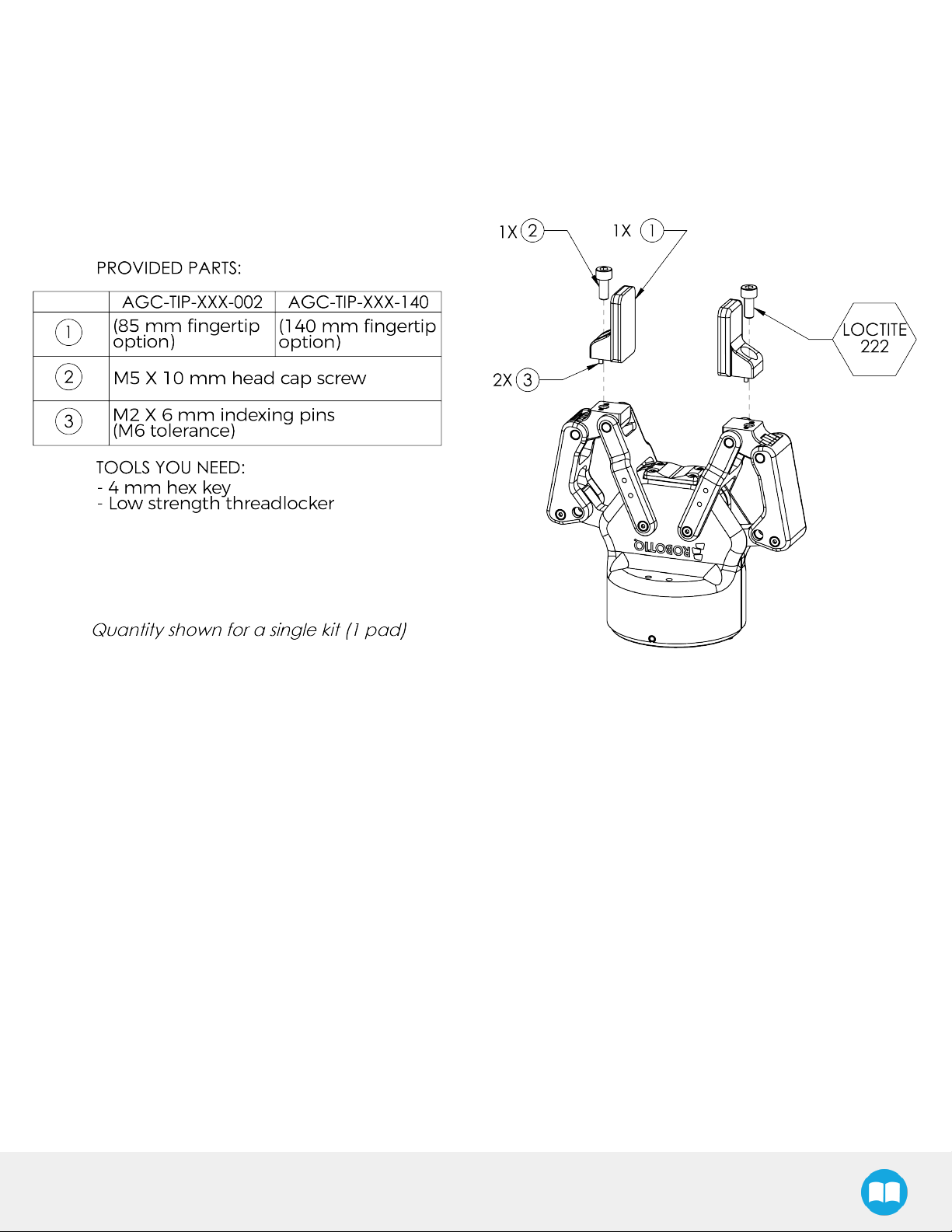
3.4.2. Installing the fingertips on the Gripper
Depending on your options, you may have fingertips to install. The second step of the installation should be to install the fingertips. To
do so:
1. Align the fingertip indexing pins with the finger dowel holes.
2. Insert the M5 X 10 low head cap screws and screw on after applying low strength threadlocker.
Fig. 3-2: Installing the fingertips on the Gripper
2F-85 &2F-140 - Instruction Manual
Page 22
22
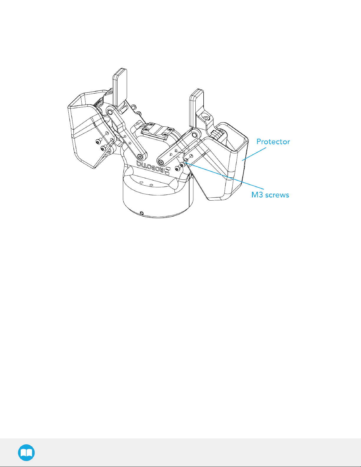
3.4.3. Installing a Protector Kit on the Gripper Fingers
An optional protector kit (AGC-PRO-KIT-V4) can be ordred to cover the fingers of the 2F-85 and therefore protect users and assets
against pinch points.
You can install them using eight (8) M3 screws.
Fig. 3-3: Protector Kit Installation
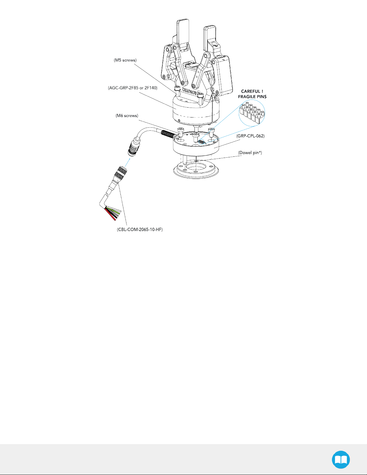
3.4.4. Installing the Gripper onto the robot
Single Gripper
You must use a coupling to attach the Gripper to the robot.
Here are the steps to follow to mount the Gripper on the robot (exploded view in the figure below). Note that all screws must be locked
in place using medium strength threadlocker.
1. Screw the coupling to the robot wrist; align properly with the dowel pin
2. Fasten the Gripper to the coupling
2F-85 &2F-140 - Instruction Manual
Page 23
23
Fig. 3-4: Installing a Gripper on the robot wrist
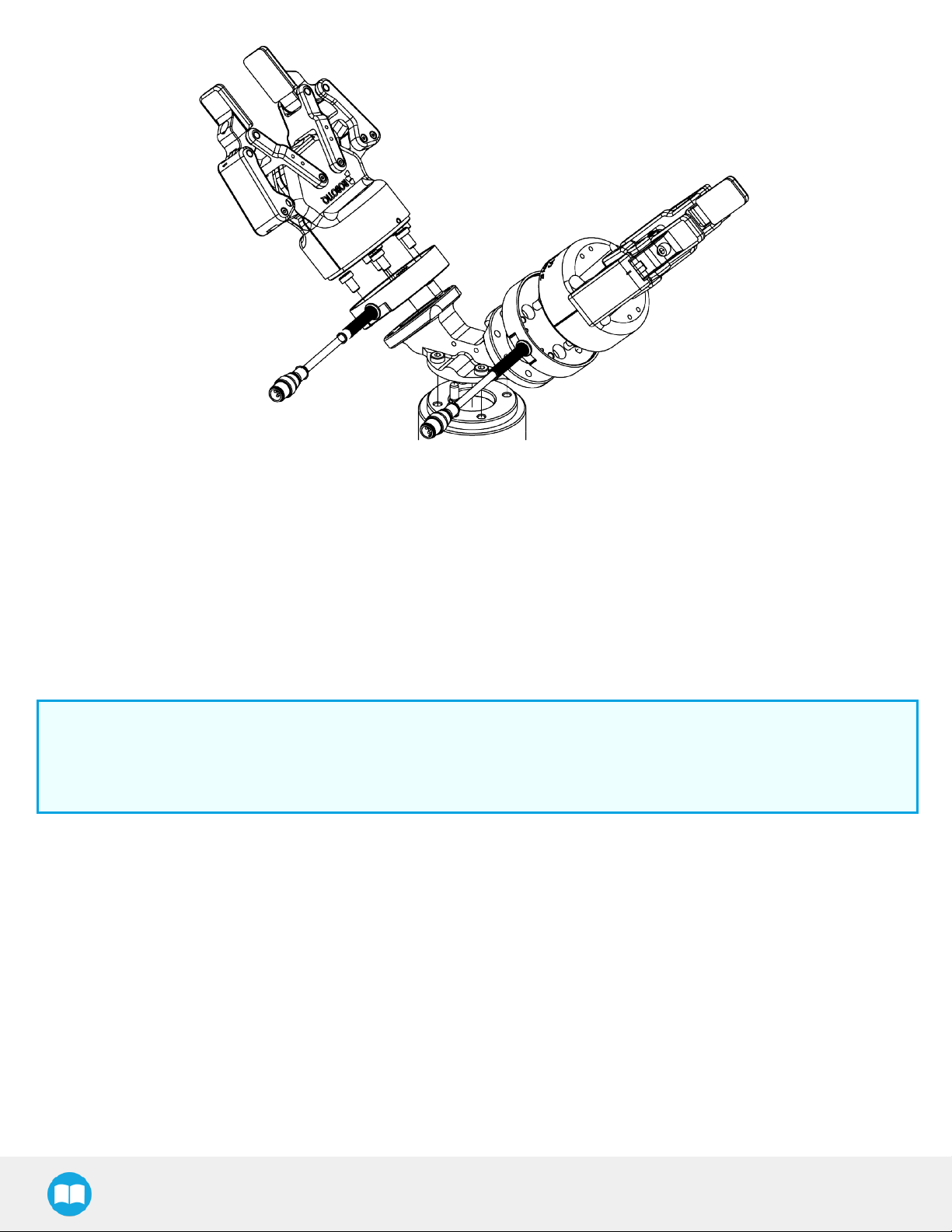
Multiple Grippers
When installing multiple grippers on one robot, every gripper must have its own coupling.
1. Install a mounting plate (not provided) first on the robot arm (AGC-APL-159-02).
2. Mount the gripper couplings on the mounting plate using the provided M6 X 10 mm screws.
3. Mount the grippers onto their coupling using the provided M5 X 35 mm screws.
2F-85 &2F-140 - Instruction Manual
Page 24
24
Fig. 3-5: Exploded View of a Dual Gripper Setup
Fig. 3-6: Exploded view of a dual gripper setup
3.5. Electrical Setup
Power and communication are established with the 2-Finger Adaptive Robot Gripper via a single Device Cable. The Device Cable
provides a 24V power supply to the Gripper and enables serial RS485 communication to the robot controller. An optional Robotiq
Universal Controller may be used between the Gripper and the network / robot controller if fieldbus communication is required.
Info
RS485 signals (485+, 485- and 485 GND) are isolated from the main 24V power supply. 4 GND can be connected to any
other ground reference as long as the voltage potential between the grounds does not exceed 250V. Grounding reference is
at the user's discretion.
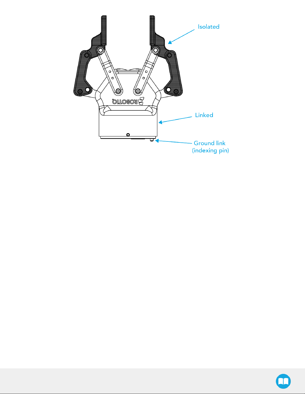
Gripper grounding is optional and is done via the robot ground. The coupling indexing pin (dowel) is the ground connector. Gripper
coupling, chassis and proximal phalanx are linked as illustrated in the figure below. They link through the coupling indexing pin to the
robot ground. Proximal bars, distal phalanx, fingertip base and fingertips are isolated.
2F-85 &2F-140 - Instruction Manual
Page 25
25
Fig. 3-7: Robotiq 2-Finger electrical isolation / grounding.
2F-85 &2F-140 - Instruction Manual
Page 26
26
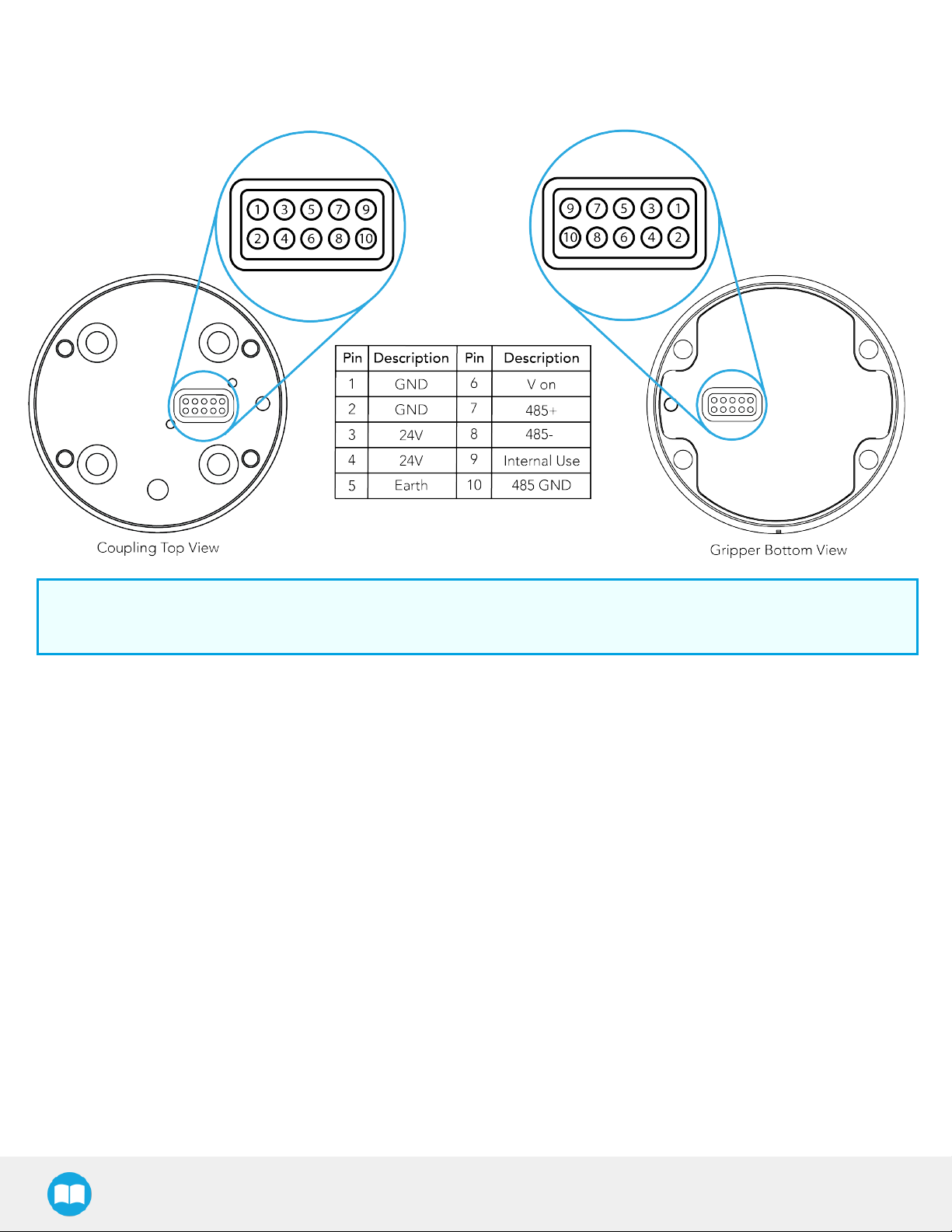
3.5.1. Pinout Interface
The Gripper interfaces with its coupling via a 10-spring pin connector located on its outer surface.
Info
The coupling used in the figure above is used for reference only and corresponds to bolt pattern ISO 9409-1-50-4-M6.
3.5.2. Coupling to controller
If a Robotiq Universal Controller is used, please refer to the Robotiq Universal Controller manual. The figure below represents the
wiring schematic of the 2-Finger with device cable, power supply, fuse (please refer to the Required Tools and Equipment section)and
grounding.
2F-85 &2F-140 - Instruction Manual
Page 27
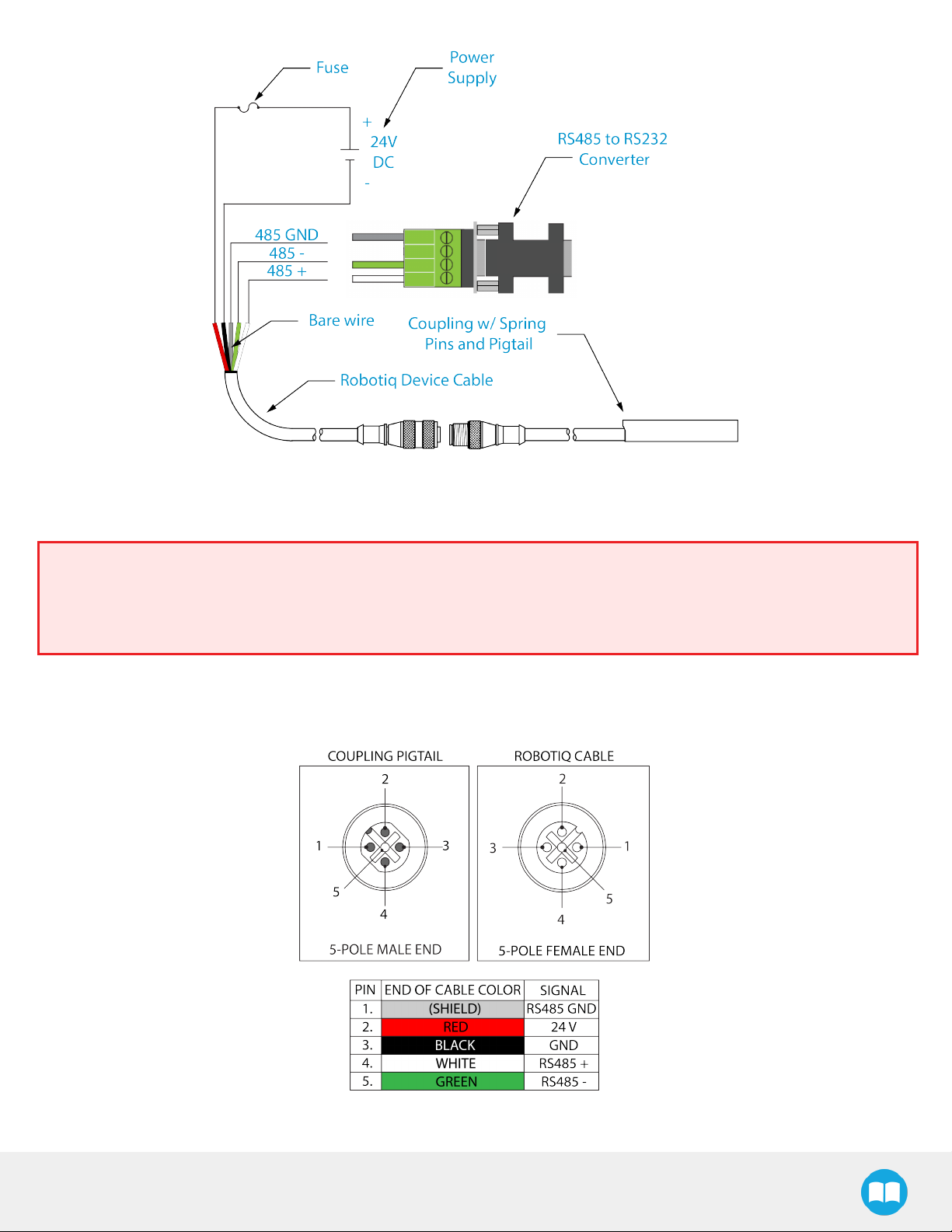
Fig. 3-8: Pigtail cable and device cable wiring schematic.
Fig. 3-9: Robotiq 2-Finger with pigtail cable and device cable wiring schematic.
27
Warning
Use proper cabling management. Be sure to have enough forgiveness in the cabling to allow movement of the Gripper along
all axes without pulling out the connectors. Always protect the controller-side (robot side) connector of the cable with a strain
relief cable clamp.
The figure below represents the 2-Finger pigtail connector from the coupling (AGC-CPL-XXX), device cable - robot side
(CBL-COM-2065-XX) and their associated pinout.
Fig. 3-10: Pinout of the 2-Finger pigtail and device cable.
2F-85 &2F-140 - Instruction Manual
Page 28
28
If additional cable is used, suggested cable specifications are as follows:
Power supply, fusing:
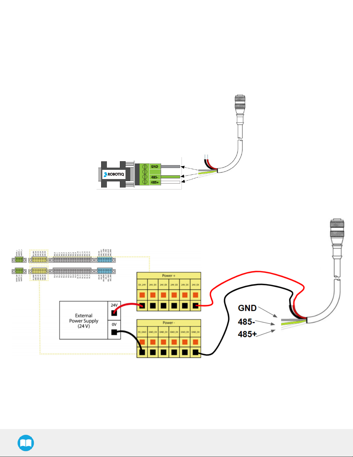
Single Gripper
Connect the white, green and bare wires to the Robotiq RS485 to RS232 signal converter (ACC-ADT-RS232-RS485) as shown in the
figure below.
Fig. 3-11: Gripper Cable to RS485/RS232 Converter
Also connect the red (24V) and black (0V) wires in the controller according to the figure below.
Fig. 3-12: Gripper Cable to Terminal Connector on the Controller
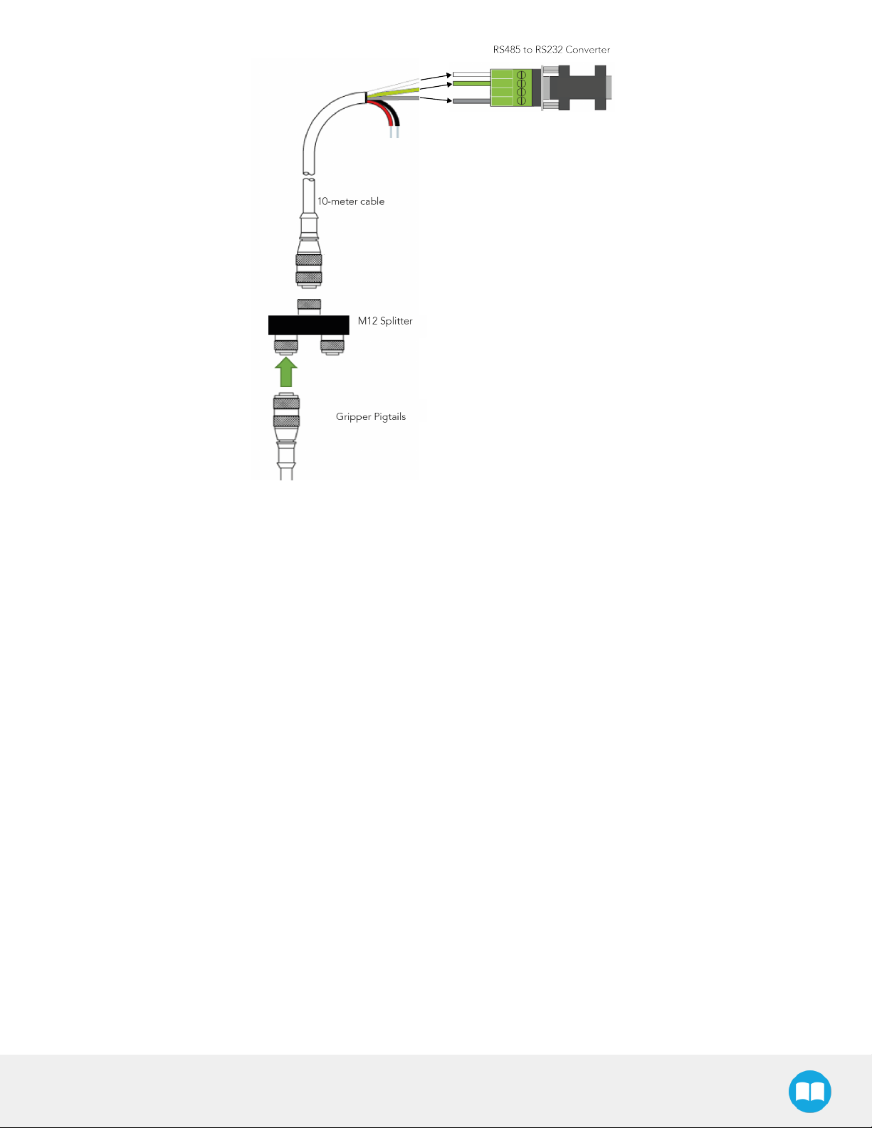
Multiple Grippers
It is possible to connect multiple grippers on the same robot. Only one RS485 to RS232 converter (ACC-ADT-RS232-RS485) must be
used. Use M12 splitters (ACC-SPLIT-M12-2:1) to connect all the grippers pigtails to one 10m cable (CBL-COM-2065-10-HF) that
connects to the RS485 to RS232 converter.
2F-85 &2F-140 - Instruction Manual
Page 29
29
Fig. 3-13: Multiple grippers wiring
2F-85 &2F-140 - Instruction Manual
Page 30

4. Control
Info
Unless specified, all values in this section are hexadecimal values.
4.1. Overview
Tip
Robotiq suggests using the Robotiq User Interface test software to explore the various features of the Gripper, like object
detection and forcecontrol.
Since the Robotiq 2-Finger has its own embedded controller, high-level commands, such as "Go to requested position" are used to
control it.
Info
30
The operator can:
l Control force, speed and position of the Gripper fingers.
l Finger movement is always synchronized, movement is initiated via a single "Go to requested position" command.
l Parallel or encompassing grasp is done automatically.
l A built in object detection feature is available, the user can be notified after an object is picked once the "Go to" command
has been initiated.
l Engage directional (open or close ) auto-release for emergencies.
Control using registers
The Gripper has an internal memory that is shared with the robot controller. One part of the memory is for the robot output;gripper
functionalities. The other part of the memory is for the robot input; gripper status. Two types of actions can then be done by the robot
controller :
1. Write in the robot output registers to activate functionalities;
2. Read in the robot input registers to get the status of the Gripper.
The Gripper Register Mapping section will map the different registers used to control the Gripper or to read its status while the Robot
Output Registers &Functionalities section will detail the output (write) register functions, and the Robot Input Registers &Status section
will detail the input (read) register status. The figure below is a representation of the memory and the control logic of the Gripper.
2F-85 &2F-140 - Instruction Manual
Page 31

31
Fig. 4-1: 2-Finger control logic overview
2F-85 &2F-140 - Instruction Manual
Page 32

4.2. Gripper Register Mapping
Register mapping
Caution
Byte numeration starts at zero and not at 1 for the functionalities and status registers.
Register Robot Output / Functionalities Robot Input / Status
Byte 0 ACTIONREQUEST GRIPPERSTATUS
Byte 1 RESERVED RESERVED
Byte 2 RESERVED FAULTSTATUS
Byte 3 POSITIONREQUEST POSREQUESTECHO
32
Byte 4 SPEED POSITION
Byte 5 FORCE CURRENT
Byte 6 to 15 RESERVED RESERVED
Table 4-1: Registers of the 2-Finger Gripper.
2F-85 &2F-140 - Instruction Manual
Page 33

33
4.3. Robot Output Registers &Functionalities
Register: ACTIONREQUEST
Address: Byte 0
Bits 7 6 5 4 3 2 1 0
Symbols Reserved rARD rATR rGTO Reserved rACT
rACT: First action to be made prior to any other actions, rACT bit will activate the Gripper. Clear rACT to reset the Gripper and clear
fault status.
l 0x0 - Deactivate Gripper.
l 0x1 - Activate Gripper (must stay on after activation routine is completed).
Warning
When setting rACT to one, the Gripper will begin movement to complete its auto-calibration feature.
Info
Power loss will set rACT; rACT bit must then be cleared, then set to allow operation of the Gripper.
Caution
rACT bit must stay on afterwards for any other action to be performed.
rGTO: The "Go To" action moves the Gripper fingers to the requested position using the configuration defined by the other registers,
rGTO will engage motion while byte 3, 4 and 5 will determine aimed position, force and speed. The only motions performed without
the rGTO bit are activation and automatic release routines.
l 0x0 - Stop.
l 0x1 - Go to requested position.
rATR: Automatic Release routine action slowly opens the Gripper fingers until all motion axes reach their mechanical limits. After all
motion is completed, the Gripper sends a fault signal and needs to be reactivated before any other motion is performed. The rATR bit
overrides all other commands excluding the activation bit (rACT).
l 0x0 - Normal.
l 0x1 - Emergency auto-release.
Caution
The automatic release is meant to disengage the Gripper after an emergency stop of the robot.
The automatic release is not intended to be used under normal operating conditions.
Automatic release will require rACT to be cleared (rACT == 0) then set (rACT == 1).
2F-85 &2F-140 - Instruction Manual
Page 34

rARD: Auto-release direction. When auto-releasing, rARD commands the direction of the movement. The rARD bit should be set prior
to or at the same time as the rATR bit, as the motion direction is set when the auto-release is initiated.
l 0x0 - Closing auto-release
l 0x1 - Opening auto-release
Register: GRIPPER OPTIONS
Address: Byte 1
Register: GRIPPER OPTIONS 2
Address: Byte 2
Bits 7 6 5 4 3 2 1 0
Symbol Reserved
34
Register: POSITIONREQUEST
Address: Byte 3
Bits 7 6 5 4 3 2 1 0
Symbol rPR
This register is used to set the target position for the Gripper's fingers. The positions 0x00 and 0xFF correspond respectively to the fully
opened and fully closed mechanical stops. For detailed finger trajectory, please refer to the Specifications section.
l 0x00 - Open position, with 85 mm or 140 mm opening respectively
l 0xFF - Closed
l Opening / count: 0.4 mm (for 85 mm stroke) and 0.65 mm (for 140 mm stroke)
Info
The activation feature of the Robotiq Adaptive Gripper will allow the Gripper to adjust to any fingertips. No matter what is
the size and shape of the fingertips used, 0 will always be fully opened and 255 fully closed, with a quasi-linear relationship
between 0 and 255.
Register: SPEED
Address: Byte 4
2F-85 &2F-140 - Instruction Manual
Page 35

35
Bits 7 6 5 4 3 2 1 0
Symbol rSP
This register is used to set the Gripper closing or opening speed in real time, however, setting a speed will not initiate a motion.
l 0x00 - Minimum speed
l 0xFF - Maximum speed
Register: FORCE
Address: Byte 5
Bits 7 6 5 4 3 2 1 0
Symbol rFR
The force setting defines the final gripping force for the Gripper. The force will fix the maximum current sent to the motor while in
motion. If the current limit is exceeded, the fingers stop and trigger an object detection notification. Please refer to the Robot Input
Registers &Status section for details on force control.
l 0x00 - Minimum force
l 0xFF - Maximum force
Info
Register bytes 6 to 15 are reserved and should be set to zero.
2F-85 &2F-140 - Instruction Manual
Page 36

4.4. Robot Input Registers &Status
Register: GRIPPERSTATUS
Address: Byte 0
Bits 7 6 5 4 3 2 1 0
36
Symbol
s
gOBJ gSTA gGTO Reserved gACT
gACT: Activation status, echo of the rACT bit (activation bit).
l 0x0 - Gripper reset.
l 0x1 - Gripper activation.
gGTO: Action status, echo of the rGTO bit (go to bit).
l 0x0 - Stopped (or performing activation / automatic release).
l 0x1 - Go to Position Request.
gSTA: Gripper status, returns the current status & motion of the Gripper fingers.
l 0x00 - Gripper is in reset ( or automatic release ) state. See Fault Status if Gripper is activated.
l 0x01 - Activation in progress.
l 0x02 - Not used.
l 0x03 - Activation is completed.
gOBJ: Object detection status, is a built-in feature that provides information on possible object pick-up. Ignore if gGTO == 0.
l 0x00 - Fingers are in motion towards requested position. No object detected.
l 0x01 - Fingers have stopped due to a contact while opening before requested position. Object detected opening.
l 0x02 - Fingers have stopped due to a contact while closing before requested position. Object detected closing.
l 0x03 - Fingers are at requested position. No object detected or object has been loss / dropped.
Caution
In some circumstances object detection may not detect an object even if it is successfully grasped. For example, picking up a
thin object in a fingertip grasp may be successful without object detection occurring. For such reasons, use this feature with
caution. In these applications when the "Fingers are at requested position" status of register gOBJ, this is sufficient to
proceed to the next step of the routine.
Tip
Checking for the correct position of the fingers (byte 4), as well as object detection (byte 0, bit 6 & 7) before proceeding to the
next step of a routine is a more reliable method than object detection or finger position alone.
2F-85 &2F-140 - Instruction Manual
Page 37

37
Register: RESERVED
Address: Byte 1
Bits 7 6 5 4 3 2 1 0
Symbol Reserved
Register: FAULTSTATUS
Address: Byte 2
Bits 7 6 5 4 3 2 1 0
Symbols kFLT
gFLT
gFLT: Fault status returns general error messages that are useful for troubleshooting. Fault LED (red) is present on the Gripper chassis,
LED can be blue, red or both and be solid or blinking.
l 0x00 - No fault (LED is blue)
l Priority faults (LED is blue)
l 0x05 - Action delayed, activation (reactivation) must be completed prior to perfmoring the action.
l 0x07 - The activation bit must be set prior to action.
Minor faults (LED continuous red)
l 0x08 - Maximum operating temperature exceeded, wait for cool-down.
l 0x09 No communication during at least 1 second.
Major faults (LED blinking red/blue) - Reset is required (rising edge on activation bit rACT needed).
l 0x0A - Under minimum operating voltage.
l 0x0B - Automatic release in progress.
l 0x0C - Internal fault; contact support@robotiq.com.
l 0x0D - Activation fault, verify that no interference or other error occurred.
l 0x0E - Overcurrent triggered.
l 0x0F - Automatic release completed.
Info
While booting, status LED will be solid blue / red.
kFLT : See your optional Controller Manual (input registers & status).
2F-85 &2F-140 - Instruction Manual
Page 38

Register: POSITIONREQUESTECHO
Address: Byte 3
Bits 7 6 5 4 3 2 1 0
Symbol gPR
gPR: Echo of the requested position for the Gripper, value between 0x00 and 0xFF.
l 0x00 - Full opening.
l 0xFF - Full closing.
Register: POSITION
Address: Byte 4
Bits 7 6 5 4 3 2 1 0
Symbol gPO
gPO: Actual position of the Gripper obtained via the encoders, value between 0x00 and 0xFF.
38
l 0x00 - Fully opened.
l 0xFF - Fully closed.
Register: CURRENT
Adress: Byte 5
Bits 7 6 5 4 3 2 1 0
Symbol gCU
gCU: The current is read instantaneously from the motor drive, value between 0x00 and 0xFF, approximate current equivalent is 10 *
value read inmA.
Tip
Built-in features like object detection and force control use the finger's electrical current readings. The user does not need to
create thesefeatures.
2F-85 &2F-140 - Instruction Manual
Page 39

39
4.5. Picking Features
As stated in previous sections, object picking is done via a simple "Go To" command, rGTO bit calls for movement, while rPR byte is
the aimed position, rSP and rFR will be the desired speed and force settings respectively. This section describes key features in object
picking applications:
l Force control
l Re-grasp
l Object detection
4.5.1. Force control
The 2-Finger Gripper gripping force is controlled via the rFR byte (refer to the Gripper Register Mapping section).The Gripper behavior
will change according to the rFR forcerequested.
l rFR = 0 :Very fragile objects or deformable objects mode
l Lowest force
l Re-grasp feature is off
l 1 rFR 127 :Solid & fragile objects
l Low torque mode
l Re-grasp feature is on
l 128 rFR 255 : Solid & strong objects
l High torque mode
l Re-grasp feature is on
The table below shows the expected applied force according to the payload material hardness, speed setting rSP and force setting
rFR. All tests were done with the 2-Finger Gripper with firmware GC3-1.3.9. Data was obtained with a Load Cell from Phidget, S Type,
model 3138.
2F-85 &2F-140 - Instruction Manual
Page 40

FINGERPAD PAYLOAD MEASURED FORCE MIN / MAX (N)
TYPE HARDNESS TYPE HARDNESS 2-Finger 85 2-Finger 140
40
Steel 4340 220 HV Steel 4340
95 HV Aluminium 6061 95 HV 25 - 220 15 - 120
Aluminium 6061
Aluminium 6061
Aluminium 6061
Aluminium 6061
Aluminium 6061
1
Available with V-Groove fingertip AGC-TIP-205-0085 / AGC-TIP-421-140.
2
Available with flat silicone fingertip AGC-TIP-204-085 / AGC-TIP-420-140.
3
HV refers to Vickers hardness test.
1
95 HV
1
95 HV Silicone rubber
1
95 HV Neoprene rubber 10 A Durometer 25 - 115 15 - 75
1
95 HV Polyurethane rubber 30 OO Durometer 25 - 115 15 - 75
1
Silicone (TIP-204)
220 HV
60 A Durometer 25 - 220 15 - 120
2
40 ADurometer
4 Durometer refers to Shore durometer hardness, scale A or scale OO.
3
4
25 - 220 15 - 120
25 - 155 15 - 100
2F-85 &2F-140 - Instruction Manual
Page 41

41
Fig. 4-2: grasp force on hardness 220 HV (4340 annealed carbon steel).
Fig. 4-3: grasp force on hardness 95 HV (6061-T6 aluminium).
2F-85 &2F-140 - Instruction Manual
Page 42

Fig. 4-4: grasp force on hardness 60A (silicone).
42
Fig. 4-5: grasp force on hardness 40 A (silicone).
2F-85 &2F-140 - Instruction Manual
Page 43

43
Fig. 4-6: grasp force on hardness 10 A (neoprene).
Fig. 4-7: grasp force on hardness 30 OO (polyurethane).
2F-85 &2F-140 - Instruction Manual
Page 44

44
4.5.2. Re-Grasp
Re-grasp feature is a built-in feature meant to prevent object lost due to slipping or inaccurate initial grip. The Re-grasp feature will
allow the Gripper to initiate movement when an object is slipping or dropped. When Re-grasping, the Gripper will attempt to close until
it reaches the position (rPR) request.
l This feature is automatically set according to the force request rFR.
Info
Feature is off at force request rFR = 0, otherwise it is on.
l Re-grasp will keep the position setting:
l Finger motion will stop when rPR position is reached, even if there is no object.
l Force and speed settings are not used, Re-grasp force and speed will automatically adjust to keep the object from being lost /
dropped.
Info
While your initial settings for force and speed are not used for Re-grasp, they will never be exceeded to prevent damaging
the object grasped.
Info
The rOBJ status is cleared when a motion is detected.
2F-85 &2F-140 - Instruction Manual
Page 45

45
4.5.3. Object detection
When the Gripper grabs an object, gOBJ status will allow you to know if object retention was successful. This is a built-in feature for the
2-Finger Grippers meant to be used by the robot controller (or PLC) commanding the overall application. The Object detection feature
will change the gOBJ status and can be used inside your robot program. As stated in the previous section:
gOBJ: Only valid if gGTO = 1.
l 0x00 - Fingers are in motion towards requested position. No object detected.
l 0x01 - Fingers have stopped due to a contact while opening before requested position. Object detected.
l 0x02 - Fingers have stopped due to a contact while closing before requested position. Object detected.
l 0x03 - Fingers are at requested position. No object detected or object has been lost / dropped.
Object detection exemple:
1. Set position, speed and force at maximum (full closing):
a. rPR == 0xFF, rSP == 0xFF, rFR ==0xFF,
2. Set ''go to requested'' will initiate movement :
a. rGTO == 0x01
3. Then object detection status will be "in motion"
a. gOBJ = 0x00
4. Until an object is picked, object detection status will then be "stopped due to contact while closing"
a. gOBJ = 0x02
5. The user can now assume it is holding the payload, and proceed to the next step.
Object lost example:
1. From previous example, after an object is picked, gOBJ = 0x02
2. If gOBJ = 0x03 after it was 0x02, user can assume the object as been lost.
2F-85 &2F-140 - Instruction Manual
Page 46

4.6. Control Logic
46
Fig. 4-8: Example of the 2-Finger control logic with associated registers.
2F-85 &2F-140 - Instruction Manual
Page 47

47
4.7. Modbus RTUCommunication
The Gripper can be controlled by Modbus RTU directly with RS485-RS232 using the ACC-ADT-RS232-RS485, or over USB using the
ACC-ADT-USB-RS485. This section is intended to provide guidelines for setting up a Modbus scanner that will adequately
communicate with the Gripper.
For a general introduction to Modbus RTU and for details regarding the CRC algorithm, the reader is invited to read the Modbus over
serial line specification and implementation guide available at: http://www.modbus.org/docs/Modbus_over_serial_line_V1_02.pdf.
For debugging purposes, the reader is also invited to download one of many free Modbus scanners such as the CAS Modbus Scanner
from Chipkin Automation Systems available at: http://www.store.chipkin.com/products/tools/cas-modbus-scanner.
Info
Modbus RTU is a communication protocol based on a Big Endian byte order. Therefore, the 16-bit register addresses are
transmitted with the most significant byte first. However, the data port is in the case of Robotiq products based on the Little
Endian byte order. As such, the data parts of Modbus RTU messages are sent with the less significant byte first.
Tip
Modbus RTU specification and details can be found at www.modbus.org.
2F-85 &2F-140 - Instruction Manual
Page 48

4.7.1. Connection Setup
The following table describes the connection requirements for controlling the Gripper using the Modbus RTU protocol.
PROPRIETY VALUE
48
Physical Interface
Baud Rate
2
115,200 bps
RS-485
1
Data Bits 8
Stop Bit
Parity
2
2
1
None
Read Holding Register (FC03)
Read Input Registers (FC04)
Supported Functions
Preset Multiple Register (FC16)
Master read & write multiple registers (FC23)
Exception Responses Not supported
Slave ID
2
0x0009 (9)
Robot Output / Gripper Input First Register 0x03E8 (1000)
Robot Input / Gripper Output First Register 0x07D0 (2000)
1
Various converters are available in the Spare parts section.
2
These parameters can be adjusted using the Robotiq User Interface.
Each register (word - 16 bits) of the Modbus RTU protocol is composed of 2 bytes (8 bits) from the Gripper. The first Gripper output
Modbus register(0x07D0) is composed from the first 2 Robotiq Gripper bytes (byte 0 and byte 1).
Info
200 Hz is the usual speed when commanding / reading from the Robotiq Gripper. It is therefore recommended to send
commands with a minimum delay of 5 ms between them.
Info
Maximum baud rate of ACC-ADT-USB-RS485 is 115200 bps.
120 Ohms termination resistor is already present on the converter.
2F-85 &2F-140 - Instruction Manual
Page 49

49
4.7.2. Read holding registers (FC03)
Function code 03 (FC03) is used for reading the status of the Gripper (robot input). Examples of such data are Gripper status, object
status, finger position, etc.
Example of FC03 Read function:
This message asks for register 0x07D0 (2000) and register 0x07D1 (2001) which contains Gripper Status, Object Detection, Fault Status
and Position Request Echo.
Request is: 09 03 07 D0 00 02 C5 CE
Bits Description
09 SlaveID
03 Function Code 03 (Read Holding Registers)
07D0 Address of the first requested register
0002 Number of registers requested (2)
C5CE Cyclic Redundancy Check (CRC)
Response is: 09 03 04 E0 00 00 00 44 33
Bits Description
09 SlaveID
03 Function Code 03 (Read Holding Registers)
04 Number of data bytes to follow (2 registers x 2 bytes/register = 4 bytes)
E000 Content of register 07D0
0000 Content of register 07D1
4433 Cyclic Redundancy Check (CRC)
2F-85 &2F-140 - Instruction Manual
Page 50

4.7.3. Read input registers (FC04)
Function code 04 (FC04) is used for requesting the status of the Gripper's analog input register. Examples of such data are Gripper
status, object status, finger position, etc.
Example of FC04 read function:
This message asks for register 0x07D0 (2000) and register 0x07D1 (2001) which contains Gripper Status, Object Detection, Fault Status
and Position Request Echo.
Request is: 09 04 07 D0 00 02 C5 CE
Bits Description
09 SlaveID
04 Function Code 03 (Read Holding Registers)
07D0 Address of the first requested register
50
0002 Number of registers requested (2)
700E Cyclic Redundancy Check (CRC)
Response is: 09 04 04 E0 00 00 00 44 33
Bits Description
09 SlaveID
04 Function Code 04 (Read Holding Registers)
04 Number of data bytes to follow (2 registers x 2 bytes/register = 4 bytes)
E000 Content of register 07D0
0000 Content of register 07D1
4584 Cyclic Redundancy Check (CRC)
2F-85 &2F-140 - Instruction Manual
Page 51

51
4.7.4. Preset multiple registers (FC16)
Function code 16 (FC16) is used to activate functionalities of the Gripper (robot output). Examples of such data are action request,
speed, force, etc.
Example of setting multiple registers FC16:
This message requests to set position request, speed and force of the Gripper by setting register 0x03E9 (1002) and 0x03EA.
Request is: 09 10 03 E9 00 02 04 60 E6 3C C8 EC 7C
Bits Description
09 SlaveID
10 Function Code 16 (Preset Multiple Registers)
03E9 Address of the first register
0002 Number of registers written to
04 Number of data bytes to follow (2 registers x 2 bytes/register = 4 bytes)
60E6 Value written to register 0x03E9
3CC8 Value written to register 0x03EA
EC7C Cyclic Redundancy Check (CRC)
Response is: 09 10 03 E9 00 02 91 30
Bits Description
09 SlaveID
10 Function Code 16 (Preset Multiple Registers)
03E9 Address of the first register
0002 Number of written registers
9130 Cyclic Redundancy Check (CRC)
2F-85 &2F-140 - Instruction Manual
Page 52

4.7.5. Master read & write multiple registers FC23
Function code 23 (FC23) is used for reading the status of the Gripper (robot input) and activating functionalities of the Gripper (robot
output) simultaneously. Examples of such data are Gripper status, object status, finger position, etc. Action requests are speed, force,
etc.
Example of reading and writing multiple registers FC23:
This message reads registers 0x07D0 (2000) and 0x07D1 (2001), which contains Gripper Status, Object Detection, Fault Status and
Position Request Echo. It also sets the position request, speed and force of the Gripper by writing to registers 0x03E9 (1001) and
0x03EA (1002).
Request is: 09 17 07 D0 00 02 03 E9 00 02 04 00 E6 3C C8 2D 0C
Bits Description
09 SlaveID
17 Function Code 23 (read and write multiple registers)
52
07D0 Address of the first requested register, read
0002 Number of registers requested (2), read
03E9 Address of the first register written to
0002 Number of registers written to (3)
04 Number of data bytes to follow (2 registers X 2 bytes/registers = 4 bytes)
00E6 Value written to register 0x03E9
3CC8 Value written to register 0x03EA
2D0C Cyclic Redundancy Check (CRC)
Response is: 09 17 04 01 00 09 E6 F6 C1
Bits Description
09 SlaveID
17 Function Code 23 (read and write multiple registers)
04 Number of data bytes to follow (2 registers x 2 bytes/register = 4 bytes)
1000 Content of register 07D0
2F-85 &2F-140 - Instruction Manual
Page 53

53
Bits Description
09E6 Content of register 07D1
F6C1 Cyclic Redundancy Check (CRC)
Note that the content of the response might change depending on the Gripper's status.
2F-85 &2F-140 - Instruction Manual
Page 54

4.7.6. Modbus RTU example
This section depicts the example given in the Control Logic section when programmed using the Modbus RTU protocol. The example
is typical of a pick and place application. After activating the Gripper, the robot is moved to a pick-up location to grasp an object. It
moves again to a second location to release the grasped object.
Step 1: Activation Request ( clear and set rACT)
Request is (clear rAct): 09 10 03 E8 00 03 06 00 00 00 00 00 00 73 30
Bits Description
09 SlaveID
10 Function Code 16 (Preset Multiple Registers)
03E8 Address of the first register
0003 Number of registers written to
54
06 Number of data bytes to follow (3 registers x 2 bytes/register = 6 bytes)
0000
0000 Value written to register 0x03EA
0000 Value written to register 0x03EB
7330 Cyclic Redundancy Check (CRC)
Response is: 09 10 03 E8 00 03 01 30
Bits Description
09 SlaveID
10 Function Code 16 (Preset Multiple Registers)
03E8 Address of the first register
Value to write to register 0x03E9 (ACTION REQUEST = 0x01 and GRIPPER OPTIONS = 0x00): rACT = 1 for "Activate
Gripper"
0003 Number of written registers
0130 Cyclic Redundancy Check (CRC)
2F-85 &2F-140 - Instruction Manual
Page 55

55
Request is (set rAct): 09 10 03 E8 00 03 06 01 00 00 00 00 00 72 E1
Bits Description
09 SlaveID
10 Function Code 16 (Preset Multiple Registers)
03E8 Address of the first register
0003 Number of registers written to
06 Number of data bytes to follow (3 registers x 2 bytes/register = 6 bytes)
0100
Value to write to register 0x03E9 (ACTION REQUEST = 0x01 and GRIPPER OPTIONS = 0x00): rACT = 1 for "Activate
Gripper"
0000 Value written to register 0x03EA
0000 Value written to register 0x03EB
72E1 Cyclic Redundancy Check (CRC)
Response is: 09 10 03 E8 00 03 01 30
Bits Description
09 SlaveID
10 Function Code 16 (Preset Multiple Registers)
03E8 Address of the first register
0003 Number of written registers
0130 Cyclic Redundancy Check (CRC)
2F-85 &2F-140 - Instruction Manual
Page 56

Step 2: Read Gripper status until the activation is completed
Request is: 09 03 07 D0 00 01 85 CF
Bits Description
09 SlaveID
03 Function Code 03 (Read Holding Registers)
07D0 Address of the first requested register
0001 Number of registers requested (1)
85CF Cyclic Redundancy Check (CRC)
Response (if the activation IS NOT completed): 09 03 02 11 00 55 D5
Bits Description
56
09 SlaveID
03 Function Code 03 (Read Holding Registers)
02 Number of data bytes to follow (1 register x 2 bytes/register = 2 bytes)
1100
55D
5
Content of register 07D0 (GRIPPER STATUS = 0x11, RESERVED = 0x00): gACT = 1 for "Gripper Activation", gSTA = 1 for
"Activation inprogress"
Cyclic Redundancy Check (CRC)
Response (if the activation IS completed): 09 03 02 31 00 4C 15
Bits Description
09 SlaveID
03 Function Code 03 (Read Holding Registers)
02 Number of data bytes to follow (1 register x 2 bytes/register = 2 bytes)
3100
Content of register 07D0 (GRIPPER STATUS = 0x31, RESERVED = 0x00): gACT = 1 for "Gripper Activation", gSTA = 3 for
"Activation is completed"
4C15 Cyclic Redundancy Check (CRC)
2F-85 &2F-140 - Instruction Manual
Page 57

57
Step 3: Move the robot to the pick-up location
Step 4: Close the Gripper at full speed and full force
Request is: 09 10 03 E8 00 03 06 09 00 00 FF FF FF 42 29
Bits Description
09 SlaveID
10 Function Code 16 (Preset Multiple Registers)
03E8 Address of the first register
0003 Number of registers written to
06 Number of data bytes to follow (3 registers x 2 bytes/register = 6 bytes)
0900
00FF
Value written to register 0x03E8 (ACTION REQUEST = 0x09 and GRIPPER OPTIONS = 0x00): rACT = 1 for "Activate
Gripper", rGTO = 1 for "Go to Requested Position"
Value written to register 0x03E9 (GRIPPER OPTIONS 2 = 0x00 and POSITION REQUEST = 0xFF): rPR = 255/255 for full
closing of the Gripper
FFFF Value written to register 0x03EA (SPEED = 0xFF and FORCE = 0xFF): full speed and full force
4229 Cyclic Redundancy Check (CRC)
Response is: 09 10 03 E8 00 03 01 30
Bits Description
09 SlaveID
10 Function Code 16 (Preset Multiple Registers)
03E8 Address of the first register
0003 Number of written registers
0130 Cyclic Redundancy Check (CRC)
2F-85 &2F-140 - Instruction Manual
Page 58

Step 5: Read Gripper status until the grasp is completed
Request is: 09 03 07 D0 00 03 04 0E
Bits Description
09 SlaveID
03 Function Code 03 (Read Holding Registers)
07D0 Address of the first requested register
0003 Number of registers requested (3)
040E Cyclic Redundancy Check (CRC)
Example of response if the grasp is not completed: 09 03 06 39 00 00 FF 0E 0A F7 8B
Bits Description
58
09 SlaveID
03 Function Code 03 (Read Holding Registers)
06 Number of data bytes to follow (3 registers x 2 bytes/register = 6 bytes)
3900
00FF
0E0A
Content of register 07D0 (GRIPPER STATUS = 0x39, RESERVED = 0x00): gACT = 1 for "Gripper Activation", gGTO = 1
for "Go to Position Request" and gOBJ = 0 for "Fingers are in motion"
Content of register 07D1 (FAULT STATUS = 0x00, POSITION REQUEST ECHO = 0xFF): the position request echo tells
that the command was well received and that the GRIPPER STATUS is valid.
Content of register 07D2 (POSITION = 0x0E, FINGER CURRENT = 0x0A): the position is 14/255 and the motor current is
100mA (these values will change during motion)
F78B Cyclic Redundancy Check (CRC)
2F-85 &2F-140 - Instruction Manual
Page 59

59
Example of response if the grasp is completed: 09 03 06 B9 00 00 FF BD 00 1D 7C
Bits Description
09 SlaveID
03 Function Code 03 (Read Holding Registers)
06 Number of data bytes to follow (3 registers x 2 bytes/register = 6 bytes)
B900
00FF
BD00
1D7C Cyclic Redundancy Check (CRC)
Content of register 07D0 (GRIPPER STATUS = 0xB9, RESERVED = 0x00): gACT = 1 for "Gripper Activation", gGTO = 1
for "Go to Position Request" and gOBJ = 2 for "Fingers have stopped due to a contact while closing"
Content of register 07D1 (FAULT STATUS = 0x00, POSITION REQUEST ECHO = 0xFF): the position request echo tells
that the command was well received and that the GRIPPER STATUS is valid.
Content of register 07D2 (POSITION = 0xBD, FINGER CURRENT = 0x00): the position is 189/255 (can be used to validate
the size of the seized object)
2F-85 &2F-140 - Instruction Manual
Page 60

Step 6: Move the robot to the release location
Step 7: Open the Gripper at full speed and full force
Request is: 09 10 03 E8 00 03 06 09 00 00 00 FF FF 72 19
Bits Description
09 SlaveID
10 Function Code 16 (Preset Multiple Registers)
03E8 Address of the first register
0003 Number of registers written to
06 Number of data bytes to follow (3 registers x 2 bytes/register = 6 bytes)
60
0900
0000
Value written to register 0x03E8 (ACTION REQUEST = 0x09 and GRIPPER OPTIONS = 0x00): rACT = 1 for "Activate
Gripper", rGTO = 1 for "Go to Requested Position"
Value written to register 0x03E9 (GRIPPER OPTIONS 2 = 0x00 and POSITION REQUEST = 0x00): rPR = 0/255 for full
opening of the Gripper (partial opening would also be possible)
FFFF Value written to register 0x03EA (SPEED = 0xFF and FORCE = 0xFF): full speed and full force
7219 Cyclic Redundancy Check (CRC)
Response is: 09 10 03 E8 00 03 01 30
Bits Description
09 SlaveID
10 Function Code 16 (Preset Multiple Registers)
03E8 Address of the first register
0003 Number of written registers
0130 Cyclic Redundancy Check (CRC)
2F-85 &2F-140 - Instruction Manual
Page 61

61
Step 8: Read Gripper status until the opening is completed
Request is: 09 03 07 D0 00 03 04 0E
Bits Description
09 SlaveID
03 Function Code 03 (Read Holding Registers)
07D0 Address of the first requested register
0003 Number of registers requested (3)
040E Cyclic Redundancy Check (CRC)
Example of response if the opening is not completed: 09 03 06 39 00 00 00 BB 10 30 E0
Bits Description
09 SlaveID
03 Function Code 03 (Read Holding Registers)
06 Number of data bytes to follow (3 registers x 2 bytes/register = 6 bytes)
3900
0000
BB10
Content of register 07D0 (GRIPPER STATUS = 0x39, RESERVED = 0x00): gACT = 1 for "Gripper Activation", gGTO = 1
for "Go to Position Request" and gOBJ = 0 for "Fingers are in motion"
Content of register 07D1 (FAULT STATUS = 0x00, POSITION REQUEST ECHO = 0x00): the position request echo tells
that the command was well received and that the GRIPPER STATUS is valid.
Content of register 07D2 (POSITION = 0xBB, FINGER CURRENT = 0x10): the position is 187/255 and the motor current is
160mA (these values will change during motion)
30E0 Cyclic Redundancy Check (CRC)
2F-85 &2F-140 - Instruction Manual
Page 62

Example of response if the opening is completed: 09 03 06 F9 00 00 00 0D 00 56 4C
Bits Description
09 SlaveID
03 Function Code 03 (Read Holding Registers)
06 Number of data bytes to follow (3 registers x 2 bytes/register = 6 bytes)
62
F900
0000
0D00
564C Cyclic Redundancy Check (CRC)
Step 9: Loop back to step 3 if other objects have to be grasped.
Content of register 07D0 (GRIPPER STATUS = 0xF9, RESERVED = 0x00): gACT = 1 for "Gripper Activation", gGTO = 1
for "Go to Position Request" and gOBJ = 3 for "Fingers are at requested position"
Content of register 07D1 (FAULT STATUS = 0x00, POSITION REQUEST ECHO = 0x00): the position request echo tells
that the command was well received and that the GRIPPER STATUS is valid.
Content of register 07D2 (POSITION = 0x0D, FINGER CURRENT = 0x00): the position is 13/255 (the fingers have reached
their software limit)
2F-85 &2F-140 - Instruction Manual
Page 63

63
4.8. Control over TM
4.8.1. TMRobots Compatibility with Robotiq Grippers
Hardware Version TMFlow Version TMGripper Component Robotiq RS232 Converter
HW1, HW2, HW3 1.68 and later 2F85_V004_XXX Compatible
4.8.2. Getting Started
1
Power ONthe robot
2
Tap the triple bar icon in the upper left corner of the screen
2F-85 &2F-140 - Instruction Manual
Page 64

3
Click on the Login icon in the navigation pane on the left
64
4
Enter your credentials and click on OK.
2F-85 &2F-140 - Instruction Manual
Page 65

65
5
Click on Get Control
6
Click on the triple bar icon in the upper left corner of the screen and select Project
2F-85 &2F-140 - Instruction Manual
Page 66

7
Click on the New Project icon in the upper left corner of the screen
66
8
Enter a name for your program and click on the OKbutton.
2F-85 &2F-140 - Instruction Manual
Page 67

67
4.8.3. TMGripper Components
Here is the list of the current Robotiq Gripper TM Components to install on TMRobots:
l GRIPPER_ROBOTIQ_2FIN85_V004_SET.Component = SET the Gripper (Speed, Force, Position)
l GRIPPER_ROBOTIQ_2FIN85_V004_GRIP.Component = CLOSE the Gripper (Action)
l GRIPPER_ROBOTIQ_2FIN85_V004_RELEASE.Component = OPENthe Gripper (Action)
l GRIPPER_ROBOTIQ_2FIN85_V004_CHANGEGRIPPER.Component = CHANGE the address of the Gripper/dual Gripper
Installation
1
Download the TMPlug &Play Software Package compression files on the official website
2
Unzip the file at the root of a blank USBstorage device
3
Rename the USBstorage device "TMROBOT"
4
Insert the USBstorage device in the robot controller
5
In TMFlow (robot software), tap the triple bar icon and select System Setting
2F-85 &2F-140 - Instruction Manual
Page 68

6
Select Import/Export
68
7
Click the Import button
2F-85 &2F-140 - Instruction Manual
Page 69

69
8
Click on TMComponent in the Robot List window and click on OK
9
Click on the Component button of the Import navigation pane
2F-85 &2F-140 - Instruction Manual
Page 70

10
Select the Components you want to import and click on the Import button
70
2F-85 &2F-140 - Instruction Manual
Page 71

71
11
Tap the triple bar icon and select Setting to display the Robot Setting window
12
Click on the Component icon
2F-85 &2F-140 - Instruction Manual
Page 72

13
Enable required Components in the Components list by ticking the radio button beside each of them
72
14
A Component that is enabled displays a green radio button; once the Components are enabled, click on the Save button
2F-85 &2F-140 - Instruction Manual
Page 73

73
15
Create a new project or open an existing project, and locate the Gripper components in the navigation pane
2F-85 &2F-140 - Instruction Manual
Page 74

Gripper Button
The user can assign Gripper Components to the Gripper button and use the latter to open and close the fingers of the Robotiq
Gripper.
1
From the TM Flow homepage, tap the triple bar icon and select the Setting icon
74
2
Click on Gripper Button
2F-85 &2F-140 - Instruction Manual
Page 75

75
3
In the Gripper Button window, tick the Using Customized Component radio button and select the Component you want to assign
to either one of the Gripper actions
4
In the popup window, select or change the Component you wish to assign to the Gripper action/button, and click OK
2F-85 &2F-140 - Instruction Manual
Page 76

Programming
SETComponent
Component Icon Component Node
76
1
Drag and drop the SETComponent icon after a program Gateway to place a SETprogram node (2FIN85_V004_SET1)
2
Tap the SETnode to highlight it and click on the pencil to edit the settings
Fig. 4-9: SETNode Settings Menu
2F-85 &2F-140 - Instruction Manual
Page 77

77
Setting Variable Type Default Description
Initialize_or_Not var_reset bool false
Set True if you want to initialize the gripper in this node. If you
only want to chenge gripping force, position or speed, you
don't need to initialize the gripper (please set false)
Set gripping force
Grip_Setting
Release_Setting
var_grip_force % 50%
var_grip_speed % 50%
var_grip_pos % 80%
var_Release_force % 50%
var_Release_speed % 50%
2F-85 0~100%=20~235N
2F-140 0~100%=10~125N
Set gripping speed
2F-85 0~100%=20~150mm/s
2F-140 0~100%=30~250mm/s
Set gripping position
2F-85 0~100%=0~85mm/s
2F-140 0~100%=0~140mm/s
Set gripping force
2F-85 0~100%=20~235N
2F-140 0~100%=10~125N
Set gripping speed
2F-85 0~100%=20~150mm/s
var_Release_pos % 80%
ComPort_Setting var_ComPort int 1
2F-140 0~100%=30~250mm/s
Set gripping position
2F-85 0~100%=0~85mm/s
2F-140 0~100%=0~140mm/s
Please set as Com1, Com2, Com3, following the com port to
which you connect the gripper.
2F-85 &2F-140 - Instruction Manual
Page 78

GRIPComponent
Component Icon Component Node
1
Drag and drop theGRIPComponent icon after a program Gateway to place a GRIPprogram node (2FIN85_V004_GRIP1)
2
Tap the GRIPnode to highlight it and click on the pencil to edit the settings
78
Fig. 4-10: GRIPNode Settings Menu
2F-85 &2F-140 - Instruction Manual
Page 79

79
Setting Variable Type Default Description
Set gripping force
Grip_Setting
(SETNode)
RELEASEComponent
Component Icon Component Node
var_grip_force % 50%
var_grip_speed % 50%
var_grip_pos % 80%
2F-85 0~100%=20~235N
2F-140 0~100%=10~125N
Set gripping speed
2F-85 0~100%=20~150mm/s
2F-140 0~100%=30~250mm/s
Set gripping position
2F-85 0~100%=0~85mm/s
2F-140 0~100%=0~140mm/s
1
Drag and drop theRELEASEComponent icon after a program Gateway to place a RELEASEprogram node
(2FIN85_V004_RELEASE1)
2
Tap the RELEASEnode to highlight it and click on the pencil to edit the settings
2F-85 &2F-140 - Instruction Manual
Page 80

80
Fig. 4-11: RELEASENode Settings Menu
Setting Variable Type Default Description
Set gripping force
var_grip_force % 50%
Release_Setting
var_grip_speed % 50%
(SETNode)
var_grip_pos % 80%
2F-85 0~100%=20~235N
2F-140 0~100%=10~125N
Set gripping speed
2F-85 0~100%=20~150mm/s
2F-140 0~100%=30~250mm/s
Set gripping position
2F-85 0~100%=0~85mm/s
2F-140 0~100%=0~140mm/s
2F-85 &2F-140 - Instruction Manual
Page 81

81
CHANGEGRIPPERComponent
Component Icon Component Node
1
Drag and drop theCHANGEGRIPPERComponent icon after a program Gateway to place a CHANGEGRIPPERprogram node
(2FIN85_V004_CHANGEGRI)
2
Tap the CHANGEGRIPPERnode to highlight it and click on the pencil to edit the settings
2F-85 &2F-140 - Instruction Manual
Page 82

Setting Variable Type Default Description
Change_Gripper Var_Slave_ID int 9 Select the Slave ID as the current gripper
Info
Use the Robotiq User Interface to change the Modbus Slave ID Address of the second gripper when using a dual gripper
(Default = 9).
82
2F-85 &2F-140 - Instruction Manual
Page 83

83
Changing the ModbusSlave ID
The user can change the ModbusSlave IDof a Robotiq Gripper via the Robotiq User Interface.
Installer
Browse to the support page of the Gripper in the Software section to download the RUI installer (.exe).
Robotiq User Interface
Browse to the support page of the Gripper, in the Documents section, to access or download the instruction manual of the
Robotiq User Interface (RUI) for information on the installation and control of the RUI.
1
First, click on the Modbus RTUParameters tab
2F-85 &2F-140 - Instruction Manual
Page 84

2
Change the Slave IDof the Gripper by typing in the corresponding box
3
Click on the Apply button
84
4
Perform a power cycle (24 V) while the USBdevice remains connected.
2F-85 &2F-140 - Instruction Manual
Page 85

5. User Interface
Visit support.robotiq.com to get the latest installer of the Robotiq User Interface along with appropriate documentation.
See the instruction manual of the Robotiq User Interface for more details.
85
2F-85 &2F-140 - Instruction Manual
Page 86

6. Specifications
Caution
The following manual uses the metric system, unless specified, all dimensions are in millimeters.
The following subsections provide data on the various specifications for the Robotiq 2-Finger 85 and 140 Adaptive Grippers.
l Section 6.1 lists the technical dimensions of the Grippers
l Dimensions for custom (blank) coupling
l Dimensions of all available couplings
l Dimensions for custom fingertip
l Dimensions of all available fingertips
l Section 6.2 presents the mechanical specifications of the Grippers.
l Section 6.3 gives electrical specifications for the Grippers.
86
2F-85 &2F-140 - Instruction Manual
Page 87

87
6.1. Technical dimensions
The 2-Finger 85 and 2-Finger 140 share the same basic chassis and thus have the same technical dimensions for everything except the
fingers. Figure 6-1 represents the Robotiq 2-Finger 85 Adaptive Robot Gripper's dimensions with axis X, Y, Z and origin referenced for
finger motion. Figure 6-3 will show the equivalent with 140 mm fingers (2-Finger 140).
Info
All technical drawings in the present section are shown with silicone flat fingertip option: AGC-TIP-204-085 (2-Finger 85) or
AGC-TIP-420-140 (2- Finger 140).
Fig. 6-1: 2F-85 general dimensions (opened).
As mentioned in the figure above, height and width of the fingers vary with opening position. Figure 6-1 represents the 2F-85 Gripper in
the opened position (position request = 0), while Figure 6-2 represents the 2F-85 Gripper in the closed position (position request =
255).
2F-85 &2F-140 - Instruction Manual
Page 88

88
Fig. 6-2: 2F-85 dimensions (closed).
2F-85 &2F-140 - Instruction Manual
Page 89

89
Fig. 6-3: 2F-140 general dimensions (opened).
2F-85 &2F-140 - Instruction Manual
Page 90

90
Fig. 6-4: 2F-140 dimensions (closed).
As mentioned in the figure above, the height and width of the fingers vary with opening position. Figure 6-3 represents the 2F-140
Gripper in the opened position (position request = 0), while Figure 6-4 represents the 2F-140 Gripper in the closed position (position
request = 255).
2F-85 &2F-140 - Instruction Manual
Page 91

91
6.1.1. Couplings
The Robotiq 2-Finger Adaptive Robot Gripper requires a coupling provided by Robotiq to operate. The coupling is mandatory since it
integrates electronics and electrical contacts.
Info
The coupling is common to both the 2F-85 and the 2F-140.
Blank coupling
Below are the dimensions of the blank coupling, AGC-CPL-BLANK-002 (refer to the Spare Parts, Kits and Accessories section), available
to create a custom bolt pattern. Blue section can be fully customized (holes can be place in any part of this section) while the grey
section can only be worked to a depth of3mm.
Fig. 6-5: Blank coupling AGC-CPL-BLANK-002 workable area dimensions.
2F-85 &2F-140 - Instruction Manual
Page 92

Coupling for ISO 9409-1-50-4-M6
Bolt pattern for coupling AGC-CPL-062-002 (refer to the Spare Parts, Kits and Accessories section) is compatible with :
l 50 mm pitch circle diameter :
l (4) M6-1.0 low head socket cap screw clearance
l (1) M6 indexing pin
l ISO 9409-1 standard 50-4-M6
92
Fig. 6-6: Coupling for ISO 9409-1-50-4-M6.
2F-85 &2F-140 - Instruction Manual
Page 93

93
Coupling for ISO 9409-1-31.5-4-M5
Bolt pattern for coupling AGC-CPL-063-002 (refer to the Spare Parts, Kits and Accessories section) is compatible with :
l 31.5 mm pitch circle diameter :
l (4) M5-0.8 low head socket cap screw clearance
l (1) M5 indexing pin
l ISO 9409-1 standard 31.5-4-M5
Fig. 6-7: Coupling for ISO 9409-1-31.5-4-M5.
2F-85 &2F-140 - Instruction Manual
Page 94

Coupling for ISO 9409-1-40-4-M6
Bolt pattern for coupling AGC-CPL-064-002 (refer to the Spare Parts, Kits and Accessories section) is compatible with :
l 40 mm pitch circle diameter :
l (4) M6-1.0 low head socket cap screw clearance
l (1) M6 indexing pin
l ISO 9409-1 standard 40-4-M6
94
Fig. 6-8: Coupling for ISO 9409-1-40-4-M6.
2F-85 &2F-140 - Instruction Manual
Page 95

95
Coupling for PCD 56 with 8 x M4
Bolt pattern for coupling AGC-CPL-065-002 (refer to the Spare Parts, Kits and Accessories section) is compatible with :
l 56 mm pitch circle diameter :
l (8) M4-0.7 low head socket cap screw clearance
l (1) M4 indexing pin
l 62 mm diameter internal insert
Fig. 6-9: Coupling for PCD 56 mm with 8 x M4 clearance.
Info
Although coupling AGC-CPL-065-002 is compatible with 8 x M4 threads on a 56 mm PCD it uses only 6 of the 8 normally
present holes.
2F-85 &2F-140 - Instruction Manual
Page 96

Coupling for PCD 56 with 6 x M4
Bolt pattern for coupling AGC-CPL-066-002 (refer to the Spare Parts, Kits and Accessories section) is compatible with:
l 56 mm pitch circle diameter:
l (6) M4-0.7 low head socket cap screw clearance
l (1) M6 indexing pin
l 42 mm diameter external insert
96
Fig. 6-10: Coupling for PCD 56 mm with 6 x M4 clearance.
2F-85 &2F-140 - Instruction Manual
Page 97

97
Coupling for PCD 60 with 4 x M5
Bolt pattern for coupling AGC-CPL-067-002 (refer to the Spare Parts, Kits and Accessories section) is compatible with :
l 60 mm pitch circle diameter :
l (4) M5-0.8 low head socket cap screw clearance
l (1) M5 indexing pin
l 34 mm diameter external insert
Fig. 6-11: Coupling for PCD 60 mm with 4 x M5 clearance.
2F-85 &2F-140 - Instruction Manual
Page 98

Coupling for PCD 63 with 6 x M6
Bolt pattern for coupling AGC-CPL-068-002 (refer to the Spare Parts, Kits and Accessories section) is compatible with :
l 63 mm pitch circle diameter :
l (6) M6-1.0 low head socket cap screw clearance
l (2) M6 indexing pins
98
Fig. 6-12: Coupling for PCD 63 mm with 6 x M6 clearance.
2F-85 &2F-140 - Instruction Manual
Page 99

99
6.1.2. Fingertips
The contact grasp points for the Robotiq 2-Finger Adaptive Robot Gripper are its two fingertip pads and palm pad. Many fingertips are
available from Robotiq (refer to the Spare Parts, Kits and Accessories section). The user can customize their own fingertips from blanks
or create them from scratch. The figure below represents the distal phalanx (which acts as the fingertip holder) the permanent, non
customizable part of the Gripper finger on which the fingertip must be mounted.
Custom fingertip designs must abide by the following:
l Fingertip must not exceed 100 mm in height from the fingertip's base.
l Fingertip must not exceed 100 mm in width from the fingertip's base (refer to Y axis from figure 6-18).
l Refer to the Mechanical specifications section to evaluate the grasp force according to your fingertip design.
l Applied forces to the gripper must not exceed moment and force limits detailed in the Moment and force limits section.
Info
Both 2-Finger 85 and 2-Finger 140 use the same fingertips and finger holder.
Fig. 6-13: Distal phalanx for holding standard or custom fingertips.
Tip
Custom fingertips will still be subject to the equilibrium line rule for proper actuation of the Gripper, see General Presentation
section.
2F-85 &2F-140 - Instruction Manual
Page 100

Flat silicone fingertip
The figure below represents a flat silicone fingertip AGC-TIP-204-085 (2F-85) and AGC-TIP-420-140 (2F-140); please refer to the Spare
Parts, Kits and Accessories section. This fingertip has a flat silicone surface with an optimal friction coefficient for picking objects while
the other surface will mount onto the fingertip holder shown in the Fingertips section.
Fig. 6-14: Flat silicone fingertip AGC-TIP-204-085
Fig. 6-15: Flat silicone fingertip AGC-TIP-420-140
2F-85 &2F-140 - Instruction Manual
 Loading...