

Page 1
AX2550
AX2850
Dual Channel
High Power
Digital Motor
Controller
User’s Manual
v1.9b, June 1, 2007
visit www.roboteq.com to download the latest revision of this manual
©Copyright 2003-2007 Roboteq, Inc.
Page 2

2 AX2550 Motor Controller User’s Manual Version 1.9b. June 1, 2007
Page 3

Revision History
Revision History
Date Version Changes
June 1, 2007 1.9b Added Output C active when Motors On
Fixed Encoder Limit Switches
Protection in case of Encoder failure in Closed Loop Speed
Added Short Circuit Protection (with supporting hardware)
Added Analog 3 and 4 Inputs (with supporting hardware)
Added Operating Mode Change on-the-fly
Changeable PWM frequency
Selectable polarity for Dead Man Switch
Modified Flashing Pattern
Separate PID Gains for Ch1 and C2, changeable on-the-fly
Miscellaneous additions and correction
Added Amps Calibration option
January 10, 2007 1.9 Changed Amps Limit Algorithm
Miscellaneous additions and correction
Console Mode in Roborun
March 7, 2005 1.7b Updated Encoder section.
February 1, 2005 1.7 Added Position mode support with Optical Encoder
Miscellaneous additions and corrections
April 17, 2004 1.6 Added Optical Encoder support
March 15, 2004 1.5 Added finer Amps limit settings
Enhanced Roborun utility
August 25, 2003 1.3 Added Closed Loop Speed mode
Added Data Logging support
Removed RC monitoring
August 15, 2003 1.2 Modified to cover AX2550 controller design
Changed Power Connection section
April 15, 2003 1.1 Added analog mode section
Added position mode section
Added RCRC monitoring feature
Updated Roborun utility section
Modified RS232 watchdog
March 15, 2003 1.0 Initial Release
The information contained in this manual is believed to be accurate and reliable. However,
it may contain errors that were not noticed at time of publication. User’s are expected to
perform their own product validation and not rely solely on data contained in this manual.
AX2550 Motor Controller User’s Manual 3
Page 4

4 AX2550 Motor Controller User’s Manual Version 1.9b. June 1, 2007
Page 5

Revision History 3
SECTION 1 Important Safety Warnings 13
This product is intended for use with rechargeable batteries 13
Do not Connect to a RC Radio with a Battery Attached 13
Beware of Motor Runaway in Improperly Closed Loop 13
SECTION 2 AX2550
Quick Start 15
What you will need 15
Locating the Switches, Wires and Connectors 15
Connecting to the Batteries and Motors 17
Connecting to the 15-pin Connector 18
Connecting the R/C Radio 19
Powering On the Controller 20
Button Operation 20
Default Controller Configuration 21
Connecting the controller to your PC using Roborun 22
Obtaining the Controller’s Software Revision Number 23
Exploring further 24
SECTION 3 AX2550 Motor Controller Overview 25
Product Description 25
Technical features 26
SECTION 4 Connecting Power and Motors to the Controller 29
Power Connections 29
Controller Power 30
Controller Powering Schemes 32
Powering the Controller from a single Battery 32
Powering the Controller Using a Main and Backup Battery 33
Connecting the Motors 34
Single Channel Operation 35
Converting the AX2550 to Single Channel 35
Power Fu ses 36
Wire Length Limits 37
Electrical Noise Reduction Techniques 37
Power Regeneration Considerations 37
Overvoltage Protection 38
Undervoltage Protection 38
Using the Controller with a Power Supply 39
AX2550 Motor Controller User’s Manual 5
Page 6

SECTION 5 General Operation 41
Basic Operation 41
Input Command Modes 41
Selecting the Motor Control Modes 42
Open Loop, Separate Speed Control 42
Open Loop, Mixed Speed Control 42
Closed Loop Speed Control 43
Close Loop Position Control 43
User Selected Current Limit Settings 44
Temperature-Based Current Limitation 44
Battery Current vs. Motor Current 45
Regeneration Current Limiting 46
Programmable Acceleration 47
Command Control Curves 48
Left / Right Tuning Adjustment 49
Activating Brake Release or Separate Motor Excitation 51
Emergency Shut Down Using Controller Switches 51
Emergency Stop using External Switch 51
Inverted Operation 52
Special Use of Accessory Digital Inputs 52
Using the Inputs to Activate the Buffered Output 52
Using the Inputs to turn Off/On the Power MOSFET
transistors 52
Self-Test Mode 53
SECTION 6 Connecting Sensors and Actuators to Input/Outputs 55
AX2550 Connections 55
AX2550’s Inputs and Outputs 57
I/O List and Pin Assignment 58
Connecting devices to Output C 59
Connecting Switches or Devices to Input E 60
Connecting Switches or Devices to Input F 61
Connecting Switches or Devices to EStop/Invert Input 62
Analog Inputs 63
Connecting Position Potentiometers to Analog Inputs 63
Connecting Tachometer to Analog Inputs 64
Connecting External Thermistor to Analog Inputs 66
Using the Analog Inputs to Monitor External Voltages 67
Connecting User Devices to Analog Inputs 67
Internal Voltage Monitoring Sensors 68
Internal Heatsink Temperature Sensors 68
Temperature Conversion C Source Code 69
6 AX2550 Motor Controller User’s Manual Version 1.9b. June 1, 2007
Page 7

SECTION 7 Installing, Connecting and Using the Encoder Module 71
Optical Incremental Encoders Overview 71
Recommended Encoder Types 72
Installing the Encoder Module 73
Connecting the Encoder 75
Cable Length and Noise Considerations 76
Motor - Encoder Polarity Matching 76
Voltage Levels, Thresholds and Limit Switches 76
Wiring Optional Limit Switches 78
Wiring Limit Switches Without Encoders 79
Effect of Limit Switches 79
Using the Encoder Module to Measure Distance 80
Using the Encoder to Measure Speed 80
Using the Encoder to Track Position 81
RS232 Communication with the Encoder Module 82
Encoder Testing and Setting Using the PC Utility 83
SECTION 8 Closed Loop Position Mode 85
Mode Description 85
Selecting the Position Mode 85
Position Sensor Selection 86
Sensor Mounting 86
Feedback Potentiometer wiring 87
Feedback Potentiometer wiring in RC or RS232 Mode 87
Feedback Potentiometer wiring in Analog Mode 88
Analog Feedback on Single Channel Controllers 89
Feedback Wiring in RC or RS232 Mode on Single Channel
Controllers 89
Feedback Wiring in Analog Mode on Single Channel
Controllers 89
Using Optical Encoders in Position Mode 90
Sensor and Motor Polarity 90
Encoder Error Detection and Protection 91
Adding Safety Limit Switches 91
Using Current Limiting as Protection 93
Control Loop Description 93
PID tuning in Position Mode 94
SECTION 9 Closed Loop Speed Mode 97
Mode Description 97
Selecting the Speed Mode 97
Using Optical Encoder for Speed Feedback (AX2850 only) 98
AX2550 Motor Controller User’s Manual 7
Page 8

Tachometer or Encoder Mounting 98
Tachometer wiring 98
Speed Sensor and Motor Polarity 99
Adjust Offset and Max Speed 100
Control Loop Description 100
PID tuning in Speed Mode 10 2
SECTION 10 Normal and
Fault Condition LED Messages 103
Use of the LED Display 103
Motor Direction Status 104
Fault Messages 105
No Control 105
Tem po ra r y F a u lt s 106
Permanent Faults 106
Self-Test Display 106
SECTION 11 R/C Operation 109
Mode Description 109
Selecting the R/C Input Mode 110
Connector I/O Pin Assignment (R/C Mode) 110
R/C Input Circuit Description 111
Supplied Cable Description 111
Powering the Radio from the controller 11 2
Connecting to a Separately Powered Radio 114
Operating the Controller in R/C mode 11 4
Reception Watchdog 115
R/C Transmitter/Receiver Quality Considerations 116
Joystick Deadband Programming 117
Command Control Curves 11 8
Left/Right Tuning Adjustment 118
Joystick Calibration 11 8
Automatic Joystick Calibration 119
Activating the Accessory Outputs 120
Data Logging in R/C Mode 121
SECTION 12 Analog Control and Operation 123
Mode Description 123
Connector I/O Pin Assignment (Analog Mode) 124
Connecting to a Voltage Source 125
Connecting a Potentiometer 125
Selecting the Potentiometer Value 126
8 AX2550 Motor Controller User’s Manual Version 1.9b. June 1, 2007
Page 9

Analog Deadband Adjustment 127
Power-On S afet y 128
Under Voltage Safety 128
Data Logging in Analog Mode 128
SECTION 13 Serial (RS-232) Controls and Operation 131
Use and benefits of RS232 131
Connector I/O Pin Assignment (RS232 Mode) 132
Cable configuration 133
Extending the RS232 Cable 133
Communication Settings 134
Establishing Manual Communication with a PC 134
RS232 Communication with the Encoder Module 135
Entering RS232 from R/C or Analog mode 136
Data Logging String in R/C or Analog mode 136
RS232 Mode if default 137
Commands Acknowledge and Error Messages 137
Character Echo 137
Command Acknowledgement 137
Command Error 137
Watchdog time-out 137
RS-232 Watchdog 138
Controller Commands and Queries 138
Set Motor Command Value 139
Set Accessory Output 139
Query Power Applied to Motors 140
Query Amps from Battery to each Motor Channel 140
Query Analog Inputs 140
Query Heatsink Temperatures 141
Query Battery Voltages 141
Query Digital Inputs 142
Reset Controller 142
Accessing & Changing Configuration Parameter in Flash 143
Apply Parameter Changes 143
Flash Configuration Parameters List 144
Input Control Mode 145
Motor Control Mode 145
Amps Limit 146
Acceleration 147
Input Switches Function 147
RC Joystick or Analog Deadband 148
Exponentiation on Channel 1 and Channel 2 148
Left/Right Adjust 149
Default Encoder Time Base 1 and 2 149
Default Encoder Distance Divider 150
AX2550 Motor Controller User’s Manual 9
Page 10

Default PID Gains 150
Joystick Min, Max and Center Values 150
Reading & Changing Operating Parameters at Runtime 151
Operating Modes Registers 152
Read/Change PID Values 152
PWM Frequency Register 153
Controller Status Register 153
Controller Identification Register 154
Current Amps Limit Registers 154
RS232 Encoder Command Set 155
Read Encoder Counter 155
Set/Reset Encoder Counters and Destination Registers 155
Read Speed 156
Read Distance 157
Read Speed/Distance 157
Read Encoder Limit Switch Status 157
Read / Modify Encoder Module Registers and Parameters 158
Register Description 160
Encoder Hardware ID code 160
Switch Status 160
Speed or Distance 1 or 2 160
Counter Read/Write Mailbox 161
Counter 1 and 2 161
Destination Register 1 and 2 161
Distance 1 and 2 162
Speed 1 and 2 162
Time Base 1 and 2 162
Encoder Threshold 162
Distance Divider 162
Counter Read Data Format 163
Encoder Testing and Setting Using the PC Utility 163
Automatic Switching from RS232 to RC Mode 165
Analog and R/C Modes Data Logging String Format 166
Data Logging Cables 166
Decimal to Hexadecimal Conversion Table 167
SECTION 14 Configuring the Controller using the Switches 171
Programming Methods 171
Programming using built-in Switches and Display 171
Entering Programming Mode 172
Changing parameters 173
The Special Case of Joystick Calibration 173
Restoring factory defaults 173
Exiting the Parameter Setting Mode 174
Programmable Parameters List 174
10 AX2550 Motor Controller User’s Manual Version 1.9b. June 1, 2007
Page 11

SECTION 15 Using the Roborun Configuration Utility 177
System Requirements 177
Downloading and Installing the Utility 177
Connecting the Controller to the PC 178
Roborun Frame, Tab and Menu Descriptions 179
Getting On-Screen Help 180
Loading, Changing Controller Parameters 181
Control Settings 181
Power Settings 182
Analog or R/C Specific Settings 183
Closed Loop Parameters 184
Encoder Setting and Testing 184
Encoder Module Parameters Setting 185
Exercising the Motors 186
Viewing Encoder Data 186
Running the Motors 186
Logging Data to Disk 189
Connecting a Joystick 190
Using the Console 191
Viewing and Logging Data in Analog and R/C Modes 192
Loading and Saving Profiles to Disk 192
Operating the AX2550 over a Wired or Wireless LAN 193
Updating the Controller’s Software 194
Updating the Encoder Software 195
Creating Customized Object Files 195
SECTION 16 Mechanical Specifications 197
Mechanical Dimensions 197
Mounting Considerations 198
Thermal Considerations 199
Attaching the Controller Directly to a Chassis 199
Wire Dimensions 199
Weight 200
AX2550 Motor Controller User’s Manual 11
Page 12

12 AX2550 Motor Controller User’s Manual Version 1.9b. June 1, 2007
Page 13

SECTION 1 Important Safety
Warnings
Read this Section First
The AX2550 is a high power electronics device. Serious damage, including fire,
may occur to the unit, motors, wiring and batteries as a result of its misuse.
Please review the User’s Manual for added precautions prior to applying full
battery or full load power.
This product is intended for use with rechargeable batteries
Unless special precautions are taken, damage to the controller and/or power supply
may occur if operated with a power supply alone. See“Power Regeneration Considerations” on page 37 of the Users Manual. Always keep the controller connected
to the Battery. Use the Power Control input to turn On/Off.
Do not Connect to a RC Radio with a Battery Attached
Without proper protection, a battery attached to an RC Radio may inject its voltage
directly inside the controller’s sensitive electronics. See
Beware of Motor Runaway in Improperly Closed Loop
Wiring or polarity errors between the feedback device and motor in position or
closed loop position mode may cause the controller to runaway with no possibility
to stop it until power is turned off.
AX2550 Motor Controller User’s Manual 13
Page 14

Important Safety Warnings
14 AX2550 Motor Controller User’s Manual Version 1.9b. June 1, 2007
Page 15

SECTION 2 AX2550
Quick Start
This section will give you the basic information needed to quickly install, setup and
run your AX2550 controller in a minimal configuration. The AX2850 is a version of
the AX2550 controller with the addition of Optical Encoder inputs.
What you will need
For a minimal installation, gather the following components:
• One AX2550 Controller and its provided cables
• 12V to 40V high capacity, high current battery
• One or two brushed DC motors
• One R/C to DB15 connector (provided)
• Miscellaneous wires, connectors, fuses and switch
Locating the Switches, Wires and Connectors
Take a moment to familiarize yourself with the controller’s wires, switches and con-
nectors.
AX2550 Motor Controller User’s Manual 15
Page 16
AX2550 Quick Start
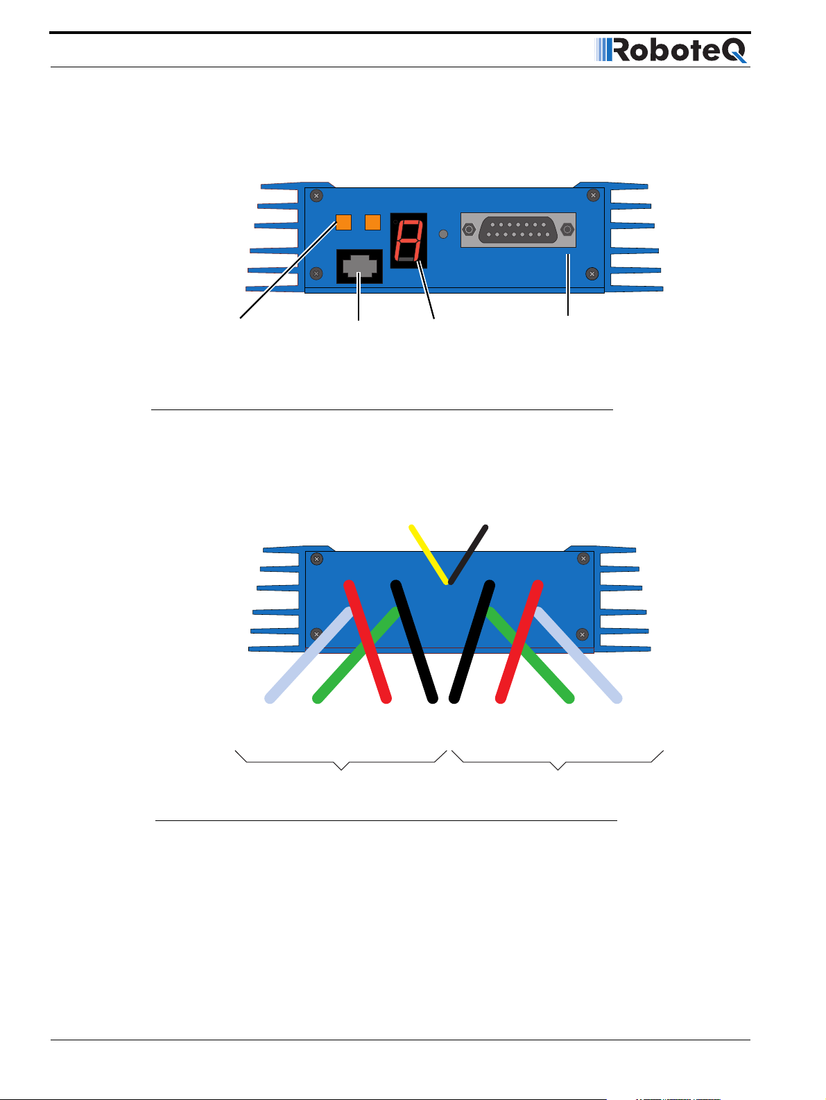
The front side (shown in Figure 1) contains the buttons and display needed to operate and
monitor the controller. The 15-pin connector provides the connection to the R/C radio, joystick or microcomputer, as well as connections to optional switches and sensors.
Program Set
Controller Configuration buttons
Connector to
Optical Encoders
(AX2850 only)
FIGURE 1. Front Controller Layout
At the back of the controller (shown in the figure below) are located all the wires that must
be connected to the batteries and the motors.
Controller Power
Power Control
Yellow
Reset
Operating Status
and Program LED
Display
Ground (-)
Black
Connector to Receiver/Controls
and sensors
(top)
Motor (+)
White
Motor (-)
Green
Motor 1
12 to 40V (+)
Red
Ground (-)
Black
12 to 40V (+)
Red
Motor 2
Motor(+)
Yellow or
White
Motor (-)
Green
FIGURE 2. Rear Controller Layout
16 AX2550 Motor Controller User’s Manual Version 1.9b. June 1, 2007
Page 17
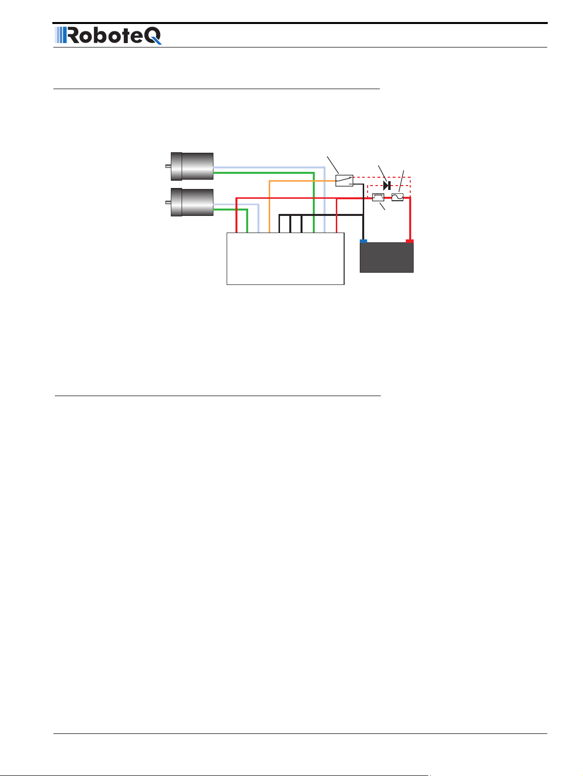
Connecting to the Batteries and Motors
Connecting to the Batteries and Motors
Connection to the batteries and motors is shown in the figure below and is done by connecting the set of wires coming out from the back of the controller.
Motor2
Motor1
Power switch
+
-
+
-
VMot
M1-
M1+
PwrCtrl
Controller
GND
GND
GND
M2-
M2+
VMot
Optional
Diode
On
Off
Optional
Emergency
Disconnect
12V to 24V
Motor Battery
Fuse
Notes:
- The Battery Power connection are doubled in order to provide the maximum current to the controller. If
only one motor is used, only one set of motor power cables needs to be connected.
- Typically, 1, 2 or 3 x 12V batteries are connected in series to reach 12, 24 or 36V respectively.
- The Power Control wire MUST be used to turn On and Off the controller.
FIGURE 3. AX2550 Electrical Power Wiring Diagram
1- Connect each motor to one of the two M+ and M- cables pairs. Make sure to respect
the polarity, otherwise the motor(s) may spin in the opposite direction than expected
2- Connect the two thick black wires to the minus (-) terminal of the battery that will be
used to power the motors. Connect the two thick red wires the two VMot terminals to the
plus (+) terminal of the battery. The motor battery may be of 12 to 40 Volts. There is no
need to insert a separate switch on Power cables, although one is suggested for Emergency disconnect. See “Controller Power” on page 30 for a detailed discussion and more
wiring options.
Avoid extending the length of wires from the battery to the controller as the added inductance may cause damage to the controller when operating at high currents. Try extending
the motor wires instead since the added inductance on the motor side of the controller is
not harmful.
The two red wires are connected to each other inside the controller. The same is true
for the black wires. You should wire each pair together as shown in the diagram
above.
3- The yellow Power Control wire and the thin black wire MUST be connected to Ground to
turn the Controller Off. For turning the controller On, even though the Power Control may
be left floating, whenever possible pull it to an unfused12V or higher voltage to keep the
controller logic solidly On. You may use a separate battery to keep the controller alive as
the main Motor battery discharges. Refer to the chapter “Connecting Power and Motors to
AX2550 Motor Controller User’s Manual 17
Page 18

AX2550 Quick Start
the Controller” on page 29 for more information about batteries and other connection
options.
Important Warning
Do not rely on cutting power to the controller for it to turn off if the Power Control is
left floating. If motors are spinning because the robot is pushed are pushed or
because of inertia, they will act as generators and will turn the controller, possibly in
an unsafe state. ALWAYS ground the Power Control wire to turn the controller Off
and keep it Off.
Important Warning
The controller includes large capacitors. When connecting the Motor Power Cables,
a spark will be generated at the connection point. This is a normal occurrence and
should be expected.
Connecting to the 15-pin Connector
The controller’s I/O are located on it’s standard 15-pin D-Sub Connector. The functions of
some pins varies depending on controller model and operating mode. Pin assignment is
found in the table below.
Signal
Pin
1 2A Digital Output C (same as pin 9)
2TxData
3 RC Ch1 RxData Unused
4 RC Ch 2 Digital Input F
5 Ground Out
6 Ground In
7 +5V In
8 Digital Input E (Not available when Encoder module is present)
9 2A Digital Output C (same as pin 1)
10 Analog Input 2
11 Analog Input 1
12 Analog Input 3 (on RevB hardware)
13 Ground Out
14 +5V Out (100mA max.)
15 Emergency Stop or Invert Switch input
RC Mode RS232 Mode Analog Mode
(Unused on RevB Hardware)
(Unused on RevB Hardware)
and Analog Input 4 (on RevB hardware only)
18 AX2550 Motor Controller User’s Manual Version 1.9b. June 1, 2007
Page 19
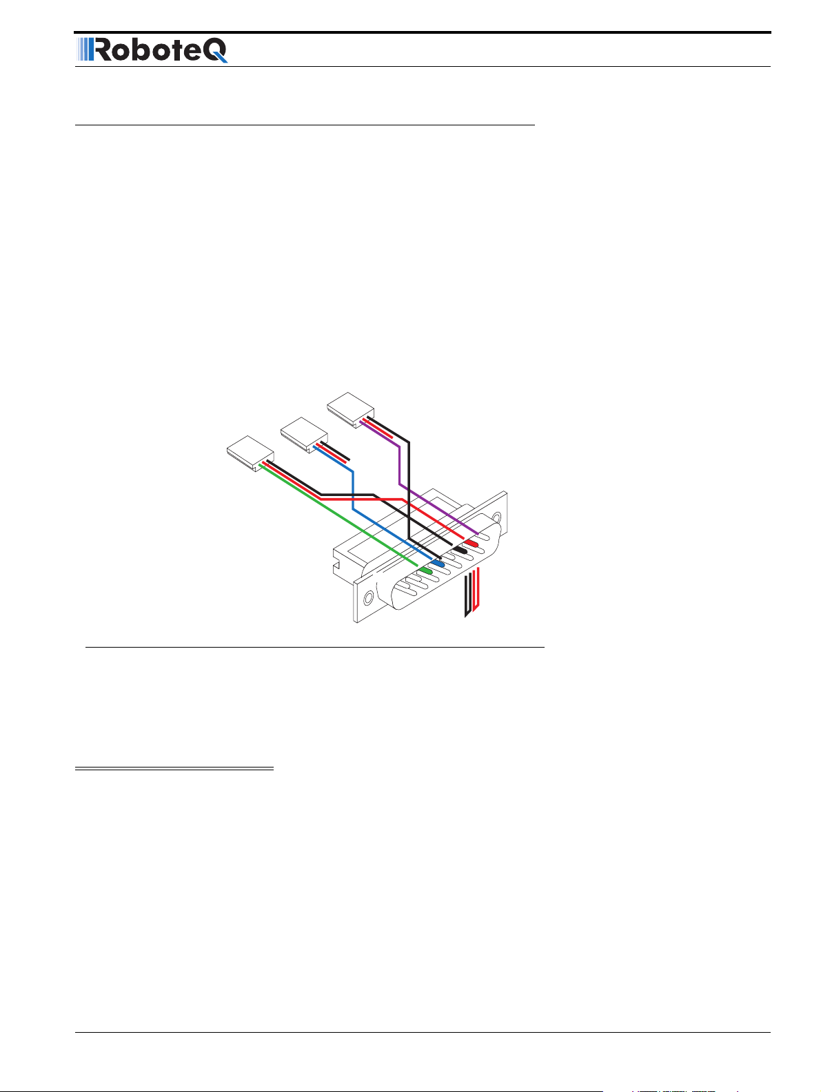
Connecting the R/C Radio
Connecting the R/C Radio
Connect the R/C adapter cables to the controller on one side and to two or three channels
on the R/C receiver on the other side. If present, the third channel is for activating the
accessory outputs and is optional.
When operating the controller in “Separate” mode, the wire labelled Ch1 controls Motor1,
and the wire labelled Ch2 controls Motor2.
When operating the controller in “Mixed” mode, Ch1 is used to set the robot’s speed and
direction, while Ch2 is used for steering.
See “R/C Operation” on page 109 of the User’s Manual for a more complete discussion on
R/C commands, calibration and other options.
Channel 3
Channel 2
Channel 1
Pin 1
15
FIGURE 4. R/C connector wiring for 3 channels and battery elimination (BEC)
This wiring - with the wire loop uncut - assumes that the R/C radio will be powered by the
AX2550 controller. Other wiring options are described in “R/C Operation” on page 109 of
the User’s Manual.
Important Warning
Do not connect a battery to the radio when the wire loop is uncut. The RC battery
voltage will flow directly into the controller and cause permanent damage if its voltage is higher than 5.5V.
3: Channel 1 Command Pulses
4: Channel 2 Command Pulses
6: Radio battery (-) Ground
7: Radio battery (+)
8: Channel 3 Command Pulses
8
9
Wire loop bringing power from
controller to RC radio
Connecting the optional channel 3 will enable you to turn on and off the accessory output.
See “Connecting Sensors and Actuators to Input/Outputs” on page 55 and “Activating the
Accessory Outputs” on page 120 of the User’s Manual.
AX2550 Motor Controller User’s Manual 19
Page 20

AX2550 Quick Start
Powering On the Controller
Important reminder: There is no On-Off switch on the controller. You must insert a switch
on the controller’s power wire as described in section“Connecting to the Batteries and
Motors” on page 17.
To power the controller, center the joystick and trims on the R/C transmitter. In Analog
mode, center the command potentiomenter or joystick.Then turn on the switch that you
have placed on the on the Power Control input.
If the R/C transmitter and/or receiver is powered off, the display on the controller will alternate the letters spelling “no ctrl” to indicate that it is On but is not receiving a control signal.
FIGURE 5. “no control” scroll message indicates no valid R/C signal is present
Turn the R/C transmitter On. The “no ctrl” scrolling message will disappear and the display
will show steady patterns depending on the motor’s selected direction.
Move the joystick on the transmitter to activate the motors to the desired speed and direction.
See “R/C Operation” on page 109 of the User’s Manual for a detailed description of the
many features and options available in the R/C mode.
Button Operation
The AX2550 has three buttons: Set, Program and Reset. These buttons are not needed
for normal operation, as the controller is immediately operational upon power up.
The Reset button will restart the controller. This button is recessed and you will need a
paper clip to press it. Reset is also accomplished by turning the controller’s power Off and
back On.
The Set and Program buttons have the following functions depending how and when they
are pressed:
TABLE 1. AX2550 Buttons Function
Prog and Set button status Function
Press and hold Program alone during reset or power up Enter the Programming Mode.
Press and hold Set alone during reset of power up Enter Self-Test mode. See “Self-Test
Mode” on page 53 of the User’s Manual
Press and hold Program and Set together during reset or
power up
Reset configuration parameters to factory
default
20 AX2550 Motor Controller User’s Manual Version 1.9b. June 1, 2007
Page 21

Default Controller Configuration
TABLE 1. AX2550 Buttons Function
Prog and Set button status Function
Press Program while Programming Mode Accept previous parameter change and
select next parameter
Press Set while in Programming mode Change value of selected parameter
Press Program pressed alone during normal operation No effect
Press Set alone during normal operation No effect
Press Program and Set together during normal operation Emergency stop
Default Controller Configuration
Version 1.9b of the AX2550 software is configured with the factory defaults shown in the
table below. Although Roboteq strives to keep the same parameters and values from one
version to the next, changes may occur from one revision to the next. Make sure that you
have the matching manual and software versions. These may be retrieved from the
Roboteq web site. See “Configuring the Controller using the Switches” on page 171 of the
User Manual for a complete configuration parameter list and their possible values.
TABLE 2. AX2550 Default Settings
Parameter Default Values Letter
Input Command mode: (0) = R/C Radio mode I
Motor Control mode (0) = Separate A, B, speed control, open loop C
Amp limit (5) = 105A A
Acceleration (2) = medium-slow S
Input switch function (3) = no action U
Joystick Deadband (2) = 16% d
Exponentiation on channel 1 (0) = Linear (no exponentiation) E
Exponentiation on channel 2 (0) = Linear (no exponentiation) F
Left / Right Adjust (7) = no adjustment L
Any one of the parameters listed in Table 2, and others not listed, can easily be changed
either using the controller’s buttons or the PC with the Roboteq Configuration Utility. See
“Using the Roborun Configuration Utility” on page 177.
The example below shows how to use the buttons to select and change the Motor Control
mode from “separate” to “mixed”. See “Configuring the Controller using the Switches” on
page 171 of the User’s Manual for a complete list of all the AX2550’s parameters and their
meanings.
AX2550 Motor Controller User’s Manual 21
Page 22
AX2550 Quick Start
Press & hold Prog
Program mode entered
Press Prog to select
Press Set to select
next value for parameter
Press Prog to store change
and select next parameter
Restart
after 10 seconds
next parameter
Reset controller
to exit
Press and hold the Prog button for 10 seconds while
resetting or powering on the controller
After 10 seconds, the controller will enter the programming mode and flash alternatively the current parameter (I= Input Mode) and its value (0= R/C mode).
Press the Prog button to move to the next parameter
(C= Motor Control Mode) and its value (0= Separate)
Press the Set button to change the parameter’s value
(1= Combined)
Press the Prog button record the change and move to
the next parameter (A= Amps limit) and it’s value (2=
75A)
Press the Reset button or power off/on the control to
restart the controller using the new parameters.
Connecting the controller to your PC using Roborun
Connecting the controller to your PC is not necessary for basic R/C operation. However, it
is a very simple procedure that is useful for the following purposes:
• to Read and Set the programmable parameters with a user-friendly graphical inter-
face
• to obtain the controller’s software revision and date
• to send precise commands to the motors
• to read and plot real-time current consumption value
• Save captured parameters onto disk for later analysis
• to update the controller’s software
22 AX2550 Motor Controller User’s Manual Version 1.9b. June 1, 2007
Page 23
Obtaining the Controller’s Software Revision Number
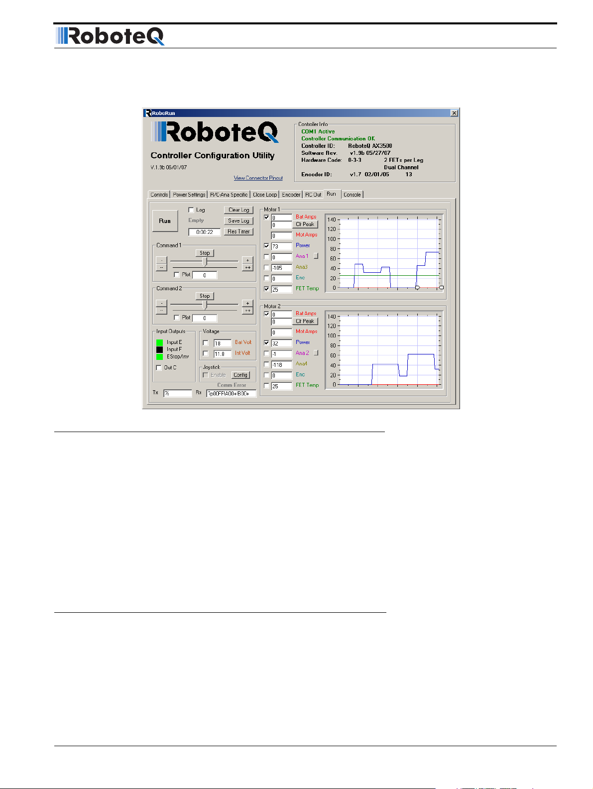
FIGURE 6. Roborun Utility screen layout
To connect the controller to your PC, use the provided cable. Connect the 15-pin connector
to the controller. Connect the 9-pin connector to your PC’s available port (typically COM1) -
use a USB to serial adapter if needed. Apply power to the controller to turn it on.
Load your CD or download the latest revision of Roborun software from
www.Roboteq.com, install it on your PC and launch the program. The software will automatically establish communication with the controller, retrieve the software revision number and present a series of buttons and tabs to enable its various possibilities.
The intuitive Graphical User Interface will let you view and change any of the controller’s
parameters. The “Run” tab will present a number of buttons, dials and charts that are used
for operating and monitoring the motors.
Obtaining the Controller’s Software Revision Number
One of the unique features of the AX2550 is the ability to easily update the controller’s
operating software with new revisions downloaded from Roboteq’s web site at
www.roboteq.com. This is useful for adding features and/or improving existing ones.
Each software version is identified with a unique number. Obtaining this number can be
done using the PC connection discussed previously.
AX2550 Motor Controller User’s Manual 23
Page 24

AX2550 Quick Start
FIGURE 7. Press and hold “Set” to display version number and enter self-test
It is also possible to get the controller to display the software version number by following
these simple steps
• Disconnect the power from the motor batteries. Power the controller only via the
Power Control input.
• Press and hold the Set button while powering or resetting the controller.
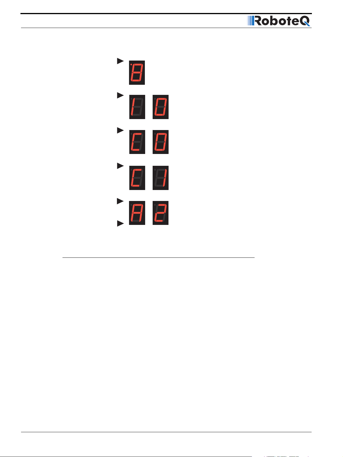
The LED will display a sequence of two numerical digits and an optional letter separated by
dashes as shown in the examples below.
= Software version 1.9b
After these digits are displayed, the controller will attempt to power the motors as part of
the self test mode (see “Self-Test Mode” on page 53 of the User’s Manual for a more
detailed explanation). This is why the motor’s battery must be disconnected. After about
30 seconds, the software revision number will be displayed again the cycle will repeat.
You will need to reset, or power down and up, the controller to exit and resume normal
operation.
Now that you know your controller’s software version number, you will be able to see if a
new version is available for download and installation from Roboteq’s web site and which
features have been added or improved.
Installing new software is a simple and secure procedure, fully described in “Updating the
Controller’s Software” on page 194 of the User’s Manual.
Exploring further
By following this quick-start section, you should have managed to get your controller to
operate in its basic modes within minutes of unpacking.
Each of the features mentioned thus far has numerous options which are discussed further
in the complete User’s Manual, including:
• Self test mode
• Emergency stop condition
• Joystick calibration
• Using Inputs/Outputs
• Current limiting
• Closed Loop Operation
• Software updating
• and much more
24 AX2550 Motor Controller User’s Manual Version 1.9b. June 1, 2007
Page 25

SECTION 3 AX2550 Motor
Controller
Overview
Congratulations! By selecting Roboteq’s AX2550 you have empowered yourself
with the industry’s most versatile, powerful and programmable DC Motor Controller
for mobile robots. This manual will guide you step by step through its many possibilities.
Product Description
The AX2550 is a highly configurable, microcomputer-based, dual-channel digital
speed or position controller with built-in high power drivers. The controller is
designed to interface directly to high power DC motors in computer controlled or
remote controlled mobile robotics and automated vehicle applications.
The AX2550 controller can accept speed or position commands in a variety of ways:
pulse-width based control from a standard Radio Control receiver, Analog Voltage
commands, or RS-232 commands from a microcontroller or wireless modem.
The controller's two channels can be operated independently or can be combined to
set the forward/reverse direction and steering of a vehicle by coordinating the
motion on each side of the vehicle. In the speed control mode, the AX2550 can
operate in open loop or closed loop. In closed loop operation, actual speed measurements from tachometers or optical encoders are used to verify that the motor is
rotating at the desired speed and direction and to adjust the power to the motors
accordingly.
The AX2550 can also be configured to operate as a precision, high torque servo controller. When connected to a potentiometer coupled to the motor assembly, the
controller will command the motor to rotate up to a desired angular position.
Depending on the DC motor's power and gear ratio, the AX2550 can be used to
move or rotate steering columns or other physical objects with very high torque.
The AX2550 is fitted with many safety features ensuring a secure power-on start,
automatic stop in case of command loss, over current protection on both channels,
and overheat protection.
AX2550 Motor Controller User’s Manual 25
Page 26

AX2550 Motor Controller Overview
The motors are driven using high-efficiency Power MOSFET transistors controlled using
Pulse Width Modulation (PWM) at 16kHz. The AX2550 power stages can operate from 12
to 40VDC and can sustain up to 120A of controlled current, delivering up to 4,800W
(approximately 6 HP) of useful power to each motor.
The many programmable options of the AX2550 are easily configured using the supplied
PC utility or one-touch Program and Set buttons and a 7-segment LED display. Once programmed, the configuration data are stored in the controller's non-volatile memory, eliminating the need for cumbersome and unreliable jumpers.
The AX2850 is the AX2550 controller fitted with a dual channel optical encoder input module. Optical Encoders allow precise motor speed and position measurement and enable
advance robotic applications.
Technical features
Fully Digital, Microcontroller-based Design
• Multiple operating modes
• Fully programmable using either built-in switches and 7 segment display or through
connection to a PC
• Non-volatile storage of user configurable settings
• Simple operation
• Software upgradable with new features
Multiple Command Modes
• Radio-Control Pulse-Width input
• Serial port (RS-232) input
• 0-5V Analog Command input
Multiple Advanced Motor Control Modes
• Independent operation on each channel
• Mixed control (sum and difference) for tank-like steering
• Open Loop or Closed Loop Speed mode
• Position control mode for building high power position servos
• Modes selectable independently for each channel
Automatic Joystick Command Corrections
• Joystick min, max and center calibration
• Selectable deadband width
• Selectable exponentiation factors for each joystick
• 3rd R/C channel input for accessory output activation (disabled when encoder mod-
ule present)
Special Function Inputs/Outputs
• 2 Analog inputs. Used as:
26 AX2550 Motor Controller User’s Manual Version 1.9b. June 1, 2007
Page 27

Technical features
• Tachometer inputs for closed loop speed control
• Potentiometer input for position (servo mode)
• Motor temperature sensor inputs
• External voltage sensors
• User defined purpose (RS232 mode only)
• 2 Extra analog inputs (on RevB hardware). Used as:
• Potentiometer input for position while in analog command mode
• User defined purpose (RS232 mode only)
• One Switch input configurable as
• Emergency stop command
• Reversing commands when running vehicle inverted
• General purpose digital input
• One general purpose 24V, 2A output for accessories
• Up to 2 general purpose digital inputs
Optical Encoder Inputs (AX2850 only)
• Inputs for two Quadrature Optical Encoders
• up to 250khz Encoder frequency per channel
• two 32-bit up-down counters
• Inputs may be shared with four optional limit switches per channel
Internal Sensors
• Voltage sensor for monitoring the main 12 to 40V battery system operation
• Voltage monitoring of internal 12V
• Temperature sensors on the heat sink of each power output stage
• Sensor information readable via RS232 port
Low Power Consumption
• On board DC/DC converter for single 12 to 40V battery system operation
• Optional backup power input for powering safely the controller if the motor batteries
are discharged
• Max 200mA at 12V or 100mA at 24V idle current consumption
• Power Control wire for turning On or Off the controller from external microcomputer
or switch
• No power consumed by output stage when motors are stopped
• Regulated 5V output for powering R/C radio. Eliminates the need for separate R/C
battery
High Efficiency Motor Power Outputs
• Two independent power output stages
• Optional Single Channel operation at double the current
• Dual H bridge for full forward/reverse operation
• Ultra-efficient 2.5mOhm (1.25mOhm on HE version) ON resistance (RDSon) MOS-
FET transistors
• Synchronous Rectification H Bridge
AX2550 Motor Controller User’s Manual 27
Page 28

AX2550 Motor Controller Overview
• 12 to 40 V operation
• High current 8 AWG cable sets for each power stages
• Temperature-based Automatic Current Limitation
• 120A up to 15 seconds (per channel)
• 100A up to 30 seconds
• 80A extended
• High current operation may be extended with forced cooling
• 250A peak Amps per channel
• 16kHz Pulse Width Modulation (PWM) output
• Auxiliary output for brake, clutch or armature excitation
• Heat sink extruded case
Advanced Safety Features
• Safe power on mode
• Optical isolation on R/C control inputs
• Automatic Power stage off in case of electrically or software induced program fail-
ure
• Overvoltage and Undervoltage protection
• Regeneration current limiting
• Watchdog for automatic motor shutdown in case of command loss (R/C and RS232
modes)
• Large, bright run/failure diagnostics on 7 segment LED display
• Programmable motor acceleration
• Built-in controller overheat sensor
• Emergency Stop input signal and button
Data Logging Capabilities
• 13 internal parameters, including battery voltage, captured R/C command, tempera-
ture and Amps accessible via RS232 port
• Data may be logged in a PC, PDA or microcomputer
Sturdy and Compact Mechanical Design
• Built from aluminum heat sink extrusion with mounting brackets
• Efficient heat sinking. Operates without a fan in most applications.
• 7” (178mm) long (excluding mounting brackets) by 5.5” wide (140mm) by 1.8”
(40mm) high
• -20o to +85o C case operating environment
• 3.3 lbs (1500g)
28 AX2550 Motor Controller User’s Manual Version 1.9b. June 1, 2007
Page 29

Power Connections
SECTION 4 Connecting
Power and
Motors to the
Controller
This section describes the AX2550 Controller’s connections to power sources and motors.
Important Warning
Please follow the instructions in this section very carefully. Any problem due to wiring errors may have very serious consequences and will not be covered by the product’s warranty.
Power Connections
The AX2550 has three Ground (black), two Vmot (red) power cables and a Power Control
wire (yellow). The power cables are located at the back end of the controller. The various
power cables are identified by their position, wire thickness and color: Red is positive (+),
black is negative or ground (-).
The power connections to the batteries and motors are shown in the figure below.
AX2550 Motor Controller User’s Manual 29
Page 30

Connecting Power and Motors to the Controller
Controller Power
Power Control
Ye l l o w
Motor (+)
White
Motor (-)
Green
12 to 40V (+)
Red
Motor 1
FIGURE 8. Controller rear plate and power wiring
Ground (-)
Black
Ground (-)
Black
12 to 40V (+)
Red
Motor(+)
Ye l l o w o r
Motor 2
(top)
Motor (-)
Green
White
Controller Power
The AX2550 uses a flexible power supply scheme that is best described in Figure 9. In this
diagram, it can be seen that the power for the Controller’s microcomputer is separate from
this of the motor drivers. The microcomputer circuit is connected to a DC/DC converter
which takes power from either the Power Control wire or the VMot input. The diode circuit
is designed to automatically select one power source over the other, letting through the
source that is higher than the other.
30 AX2550 Motor Controller User’s Manual Version 1.9b. June 1, 2007
Page 31

Controller Power
Mot1(-)
Mot1(+)
Channel 1 MOSFET Power Stage
Microcomputer &
MOSFET Drivers
Channel 2 MOSFET Power Stage
9.5V min
13V max
DC/DC
ENABLE
10.5V min
40V max
FIGURE 9. Representation of the AX2550’s Internal Power Circuits
When powered only via the Power Control input, the controller will turn On but motors will
not be able to turn until power is also present on the VMot wires
The Power Control input also ser ves as the Enable signal for the DC/DC converter. When
floating or pulled to above 1V, the DC/DC converter is active and supplies the AX2550’s
microcomputer and drivers, thus turning it On. When the Power Control input is pulled to
Ground, the DC/DC converter is stopped and the controller is turned Off.
5Vmin
40V max
5Vmin
40V max
VBatt Vmot
GND
Power
Control
&Backup
GND
GND
VBatt Vmot
Mot2(+)
Mot2(-)
The yellow Power Control wire and the thin black wire MUST be connected to Ground to
turn the Controller Off. For turning the controller On, even though the Power Control may
be left floating, whenever possible pull it to an unfused12V or higher voltage to keep the
controller logic solidly On. You may use a separate battery to keep the controller alive as
the main Motor battery discharges.
The table below shows the state of the controller depending on the voltage applied to
Power Control and Vmot.
TABLE 3. Controller Status depending on Power Control and VMot
Power Control input is
connected to
And Main Battery
Voltage is Action
Ground Any Voltage from 0V to 40V Controller is Off
Floating 0V Controller is Off. Not Recom-
mended Off Configuration.
Floating Between 8V and 10.5V Controller Logic is On
Power Stage is Disabled (undervoltage condition)
Floating Between 10.5 and 40V Controller is On.
Power Stage is Active
AX2550 Motor Controller User’s Manual 31
Page 32

Connecting Power and Motors to the Controller
TABLE 3. Controller Status depending on Power Control and VMot
Power Control input is
connected to
And Main Battery
Voltage is Action
10.5V to 40V 0V Controller is On.
Power Stage is Off
10.5V to 40V 1V to 40V Controller is On.
Power Stage is Active
All 3 ground (-) are connected to each other inside the controller. The two main battery
wires are also connected to each other internally. However, you must never assume that
connecting one wire of a given battery potential will eliminate the need to connect the
other.
Controller Powering Schemes
Powering the Controller from a single Battery
The diagram on Figure 12 show how to wire the controller to a single battery circuit and
how to turn power On and Off.
Motor2
+
-
Power on/off
switch
Fuse
Optional
Emergency
Disconnect
12V to 24V
Motor Battery
Motor1
+
VMot
M1+
M1-
GND
VCon
Controller
GND
GND
M2-
M2+
VMot
Notes:
- The Battery Power connection are doubled in order to provide the maximum current to the controller. If
only one motor is used, only one set of motor power cables needs to be connected.
- Typically, 1, 2 or 3 x 12V batteries are connected in series to reach 12V, 24V or 36V respectively.
FIGURE 10. Powering the AX2550 from a single battery
Connect the two thick black wires to the minus (-) terminal of the battery that will be used
to power the motors. Connect the two thick red wires to the plus (+) terminal of the battery. The motor battery may be of 12 to 40 Volts.
32 AX2550 Motor Controller User’s Manual Version 1.9b. June 1, 2007
Page 33

There is no need to insert a separate switch on Power cables, although for safety reasons,
it is highly recommended that a way of quickly disconnecting the Motor Power be provided
in the case of loss of control and all of the AX2550 safety features fail to activate.
The two red wires are connected to each other inside the controller. The same is true
for the black wires. You should wire each pair together as shown in the diagram
above.
The yellow Power Control wire and the thin black wire MUST be connected to Ground to
turn the Controller Off. When the controller is Off, the output transistors are in the Off position and no power is drawn on VMot.
For turning the controller On, even though the Power Control may be left floating, whenever possible pull it to an unfused12V or higher voltage to keep the controller logic solidly
On. In applications where the motors could be made to run through external force (electric
vehicle going downhill, for example), and generate 40V or more, a diode should be placed
across the fuse & emergency switch to provide a path, under all circumstances, for the
regeneration current. See “Power Regeneration Considerations” on page 37.
Important Warning
Controller Powering Schemes
Do not rely on cutting power to the controller for it to turn off if the Power Control is
left floating. If motors are spinning because the robot is pushed are pushed or
because of inertia, they will act as generators and will turn the controller On, possibly in an unsafe state. ALWAYS ground the Power Control wire to turn the controller
Off and keep it Off.
Important Warning
On versions of the AX2550 with PCB revision number lower than 5.2, the backup
power supply applied on the Power Control wire must NEVER EXCEED 13V. Permanent damage may otherwise occur. The PCB revision number can be found on the
sticker on the case’s bottom.
Important Warning
Always connect the thick black wires to ground BEFORE connecting the red wires to
the battery. If the motors are activated while the connection to ground is done solely
via the thin black wire (or the ground wire in the RS232 cable), the ground wire will
overheat and/or melt .
Powering the Controller Using a Main and Backup Battery
In typical applications, the main motor batteries will get eventually weaker and the voltage
will drop below the level needed for the internal microcomputer to properly operate. For all
professional applications it is therefore recommended to add a separate 12V (to 40V)
power supply to ensure proper powering of the controller under any conditions. This dual
battery configuration is highly recommended in 12V systems.
AX2550 Motor Controller User’s Manual 33
Page 34

Connecting Power and Motors to the Controller
Motor2
Motor1
+
-
+
-
M1-
M1+
VMot
PwrCtrl
Controller
Power switch
GND
GND
GND
FIGURE 11. Powering the AX2550 with a Main and Backup Supply
Important Warning
Unless you can ensure a steady 12V to 40V voltage in all conditions, it is recommended that the battery used to power the controller’s electronics be separate from
the one used to power the motors. This is because it is very likely that the motor batteries will be subject to very large current loads which may cause the voltage to
eventually dip below 12V as the batteries’ charge drops. The separate backup power
supply should be connected to the Power Control input.
M2-
M2+
VMot
On
Off
12V to 40V
Motor Battery
12V to 40V
Backup Battery
Connecting the Motors
Connecting the motors is simply done by connecting each motor terminal to the M1+
(M2+) and M1- (M2-) wires. Which motor terminal goes to which of the + or - controller
output is typically determined empirically.
After connecting the motors, apply a minimal amount of power using the Roborun PC utility with the controller configured in Open Loop speed mode. Verify that the motor spins in
the desired direction. Immediately stop and swap the motor wires if not.
In Closed Loop Speed or Position mode, beware that the motor polarity must match this of
the feedback. If it does not, the motors will runaway with no possibility to stop other than
switching Off the power. The polarity of the Motor or off the feedback device may need to
be changed.
Important Warning
Make sure that your motors have their wires isolated from the motor casing. Some
motors, particularly automotive parts, use only one wire, with the other connected
to the motor’s frame.
34 AX2550 Motor Controller User’s Manual Version 1.9b. June 1, 2007
Page 35

Single Channel Operation
If you are using this type of motor, make sure that it is mounted on isolators and that
its casing will not cause a short circuit with other motors and circuits which may
also be inadvertently connected to the same metal chassis.
Single Channel Operation
The AX2550’s two channel outputs can be paralleled as shown in the figure below so that
they can drive a single load with twice the power. To perform in this manner, the controller’s Power Transistor that are switching in each channel must be perfectly synchronized.
Without this synchronization, the current will flow from one channel to the other and cause
the destruction of the controller.
The controller may be ordered with the -SC (Single Channel) suffix. This version incorporates a hardware setting inside the controller which ensures that both channels switch in a
synchronized manner and respond to commands sent to channel 1.
Warning:
Use this wiring only with
+
-
-SC versions (Single
Channel) of the controller
VMot
FIGURE 12. Wiring for Single Channel Operation
Converting the AX2550 to Single Channel
The AX2550 can be easily modified into a Single Channel version by placing a jumper on
the PCB. This step must be undertook only if you have the proper tooling and technical
skills.
• Disconnect the controller from power
• Open the controller’s case by removing the front bracket and sliding the cover off
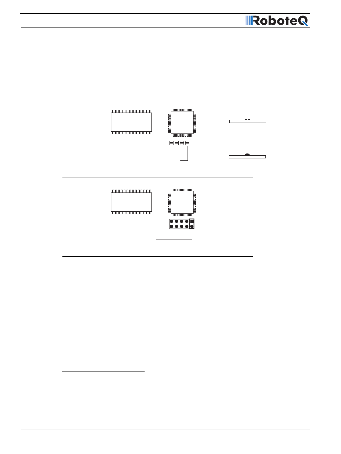
• Depending on the board’s revision, place a drop of solder on the PCB jumper pad
shown in Figure 13 or insert a jumper as shown in Figure 14.
• Place the cover and bracket back
M1-
M1+
VCon
Controller
GND
GND
GND
M2-
M2+
Pwr Ctrl
12V to 40V
GND
VMot
Before paralleling the outputs,
• Place the load on channel 1 and verify that it is activated by commands on channel
1.
AX2550 Motor Controller User’s Manual 35
Page 36
Connecting Power and Motors to the Controller
• Then place the load on channel 2 and verify that is also activated by commands on
channel 1.
• Commands on channel 2 should have no effects on either output.
It will be safe to wire in parallel the controller’s outputs only after you have verified that
both outputs react identically to channel 1 commands.
MCU
Single Channel
FIGURE 13. Solder Jumper setting for Single Channel Operation
Jumper "open"
Xilinx
Place solder ball to close
jumper and enable single
channel mode
MCU
Jumper In for
Single Channel
FIGURE 14. Jumper setting for Single Channel Operation - RevB Hardware
Xilinx
Power Fuses
For low Amperage applications (below 30A per motor), it is recommended that a fuse be
inserted in series with the main battery circuit as shown in the Figure 10 on page 32.
The fuse will be shared by the two output stages and therefore must be placed before the
Y connection to the two power wires. Fuse rating should be the sum of the expected current on both channels. Note that automotive fuses are generally slow will be of limited
effectiveness in protecting the controller and may be omitted in high current application.
The fuse will mostly protect the wiring and battery against after the controller has failed.
Important Warning
Fuses are typically slow to blow and will thus allow temporary excess current to flow
through them for a time (the higher the excess current, the faster the fuse will blow).
This characteristic is desirable in most cases, as it will allow motors to draw surges
36 AX2550 Motor Controller User’s Manual Version 1.9b. June 1, 2007
Page 37

during acceleration and braking. However, it also means that the fuse may not be
able to protect the controller.
Wire Length Limits
The AX2550 regulates the output power by switching the power to the motors On and Off
at high frequencies. At such frequencies, the wires’ inductance produces undesirable
effects such as parasitic RF emissions, ringing and overvoltage peaks. The controller has
built-in capacitors and voltage limiters that will reduce these effects. However, should the
wire inductance be increased, for example by extending the wire length, these effects will
be amplified beyond the controller’s capability to correct them. This is particularly the case
for the main battery power wires (thick red and black cables).
Important Warning
Avoid extending the black and red Motor Power wires beyond their original length,
as the added inductance may cause damage to the controller when operating at high
currents. Try extending the motor wires instead since the added inductance is less
harmful on this side of the controller.
Wire Length Limits
If the controller must be located at a longer distance, the effects of the wire inductance
may be reduced by using one or more of the following techniques:
• Twisting the power and ground wires over the full length of the wires
• Use the vehicle’s metallic chassis for ground and run the positive wire along the sur-
face
• Add a capacitor (5,000uF or higher) near the controller
Electrical Noise Reduction Techniques
As discussed in the above section, the AX2550 uses fast switching technology to control
the amount of power applied to the motors. While the controller incorporates several circuits to keep electrical noise to a minimum, additional techniques can be used to keep the
noise low when installing the AX2550 in an application. Below is a list of techniques you
can try to keep noise emission low:
• Keep wires as short as possible
• Loop wires through ferrite cores
• Add snubber R/C circuit at motor terminals
• Keep controller, wires and battery enclosed in metallic body
Power Regeneration Considerations
When a motor is spinning faster than it would normally at the applied voltage, such as
when moving downhill or decelerating, the motor acts like a generator. In such cases, the
current will flow in the opposite direction, back to the power source.
AX2550 Motor Controller User’s Manual 37
Page 38

Connecting Power and Motors to the Controller
It is therefore essential that the AX2550 be connected to rechargeable batteries. If a power
supply is used instead, the current will attempt to flow back in the power supply during
regeneration, potentially damaging it and/or the controller.
Regeneration can also cause potential problems if the battery is disconnected while the
motors are still spinning. In such a case, and depending on the command level applied at
that time, the regenerated current will attempt to flow back to the battery. Since none is
present, the voltage will rise to potentially unsafe levels. The AX2550 includes an overvoltage protection circuit to prevent damage to the output transistors (see “Overvoltage Protection” on page 38). However, if there is a possiblity that the motor could be made to spin
and generate a voltage higher than 40V, a path to the battery must be provided, even after
a fuse is blown. This can be accomplished by inserting a diode across the fuse as shown
in Figure 10 on page 32.
Please download the Application Note “Understanding Regeneration” from the
www.roboteq.com for an in-depth discussion of this complex but important topic.
Important Warning
Use the AX2550 only with a rechargeable battery as supply to the Motor Power wires
(thick black and red wires). If a transformer or power supply is used, damage to the
controller and/or power supply may occur during regeneration. See “Using the Controller with a Power Supply” on page 39 for details.
Important Warning
Avoid switching Off or cutting open the main power cables (thick black and red
wires) while the motors are spinning. Damage to the controller may occur.
Overvoltage Protection
The AX2550 includes a battery voltage monitoring circuit that will cause the output transistors to be turned Off if the main battery voltage applied on the thick red and black wires
rises above 43V.
This protection is designed to prevent the voltage created by the motors during regeneration to be “amplified” to unsafe levels by the switching circuit.
The controller will resume normal operation when the measured voltage drops below 43V.
Undervoltage Protection
In order to ensure that the power MOSFET transistors are switched properly, the AX2550
monitors the internal 12V power supply that is used by the MOSFET drivers. If the internal
voltage drops below 10V, the controller’s output stage is turned Off. The rest of the control-
ler’s electronics, including the microcomputer, will remain operational as long as the internal voltage is above 8V.
The internal voltage will be the output of the DC/DC converter which will be a solid 12V as
long as either of the main battery or backup voltage is higher than 12.5V. If the main and
38 AX2550 Motor Controller User’s Manual Version 1.9b. June 1, 2007
Page 39

Using the Controller with a Power Supply
backup voltage drop below 12.V, the DC/DC converter’s output will be approximately 0.5V
lower than the highest input.
Using the Controller with a Power Supply
Using a transformer or a switching power supply is possible but requires special care, as
the current will want to flow back from the motors to the power supply during regeneration. As discussed in “Power Regeneration Considerations” on page 37, if the supply is not
able to absorb and dissipate regenerated current, the voltage will increase until the overvoltage protection circuit cuts off the motors. While this process should not be harmful to
the controller, it may be to the power supply, unless one or more of the protective steps
below is taken:
• Use a power supply that will not suffer damage in case a voltage is applied at its
output that is higher than the transformer’s own output voltage. This information is
seldom published in commercial power supplies, so it is not always possible to
obtain positive reassurance that the supply will survive such a condition.
• Avoid deceleration that is quicker than the natural deceleration due to the friction in
the motor assembly (motor, gears, load). Any deceleration that would be quicker
than natural friction means that braking energy will need to be taken out of the system, causing a reverse current flow and voltage rise. See “Programmable Acceleration” on page 47.
• Place a battery in parallel with the power supply output. This will provide a reservoir
into which regeneration current can flow. It will also be very helpful for delivering
high current surges during motor acceleration, making it possible to use a lower
current power supply. Batteries mounted in this way should be connected for the
first time only while fully charged and should not be allowed to discharge. The
power supply will be required to output unsafe amounts of current if connected
directly to a discharged battery. Consider using a decoupling diode on the power
supply’s output to prevent battery or regeneration current to flow back into the
power supply.
• Place a resistive load in parallel with the power supply, with a circuit to enable that
load during regeneration. This solution is more complex but will provide a safe path
for the braking energy into a load designed to dissipate it. To prevent current from
flowing from the power supply into the load during normal operation, an active
switch would enable the load when the voltage rises above the nominal output of
the power supply.
AX2550 Motor Controller User’s Manual 39
Page 40

Connecting Power and Motors to the Controller
40 AX2550 Motor Controller User’s Manual Version 1.9b. June 1, 2007
Page 41

Basic Operation
SECTION 5 General
Operation
This section discusses the controller’s normal operation in all its supported operating
modes.
Basic Operation
The AX2550’s operation can be summarized as follows:
• Receive commands from a radio receiver, joystick or a microcomputer
• Activate the motors according to the received command
• Perform continuous check of fault conditions and adjust actions accordingly
Multiple options are available for each of the above listed functions which can be combined
to produce practically any desired mobile robot configuration.
Input Command Modes
The controller will accept commands from one of the following sources
• R/C radio
• Serial data (RS232)
• Analog signal (0 to 5V)
A detailed discussion on each of these modes and the available commands is provided in
the following dedicated chapters: “R/C Operation” on page 109, “Serial (RS-232) Controls
and Operation” on page 131, and “Analog Control and Operation” on page 123.
The controller’s factory default mode is R/C radio. The mode can be changed using any of
the methods described in “Programming using built-in Switches and Display” on page 171
and “Loading, Changing Controller Parameters” on page 181.
AX2550 Motor Controller User’s Manual 41
Page 42

General Operation
Selecting the Motor Control Modes
For each motor, the AX2550 supports multiple motion control modes. The controller’s fac-
tory default mode is Open Loop Speed control for each motor. The mode can be changed
using any of the methods described in “Programming using built-in Switches and Display”
on page 171 and “Loading, Changing Controller Parameters” on page 181.
Open Loop, Separate Speed Control
In this mode, the controller delivers an amount of power proportional to the command
information. The actual motor speed is not measured. Therefore the motors will slow
down if there is a change in load as when encountering an obstacle and change in slope.
This mode is adequate for most applications where the operator maintains a visual contact
with the robot.
In the separate speed control mode, channel 1 commands affect only motor 1, while channel 2 commands affect only motor 2. This is illustrated in Figure 15 below.
Controller
FIGURE 15. Examples of effect of commands to motors in separate mode
Open Loop, Mixed Speed Control
This mode has the same open loop characteristics as the previously described mode. However, the two commands are now mixed to create tank-like steering when one motor is
used on each side of the robot: Channel 1 is used for moving the robot in the forward or
reverse direction. Channel 2 is used for steering and will change the balance of power on
each side to cause the robot to turn.
Figure 16 below illustrates how the mixed mode works.
42 AX2550 Motor Controller User’s Manual Version 1.9b. June 1, 2007
Page 43

Selecting the Motor Control Modes
Controller
FIGURE 16. Effect of commands to motors examples in
mixed mode
Closed Loop Speed Control
In this mode, illustrated in Figure 18, an analog tachometer or an optical encoder (AX2850
only) is used to measure the actual motor speed. If the speed changes because of changes
in load, the controller automatically compensates the power output. This mode is preferred
in precision motor control and autonomous robotic applications. Details on how to wire the
tachometer can be found in “Connecting Tachometer to Analog Inputs” on page 64.
Closed Loop Speed control operation is described in “Closed Loop Speed Mode” on
page 97.
FIGURE 17. Motor with tachometer or Encoder for Closed Loop Speed operation
Close Loop Position Control
In this mode, illustrated in Figure 18, the axle of a geared down motor is coupled to a
potentiometer that is used to compare the angular position of the axle versus a desired
position. This AX2550 feature makes it possible to build ultra-high torque “jumbo servos”
that can be used to drive steering columns, robotic arms, life-size models and other heavy
loads. Details on how to wire the position sensing potentiometers and operating in this
mode can be found in “Closed Loop Position Mode” on page 85.
AX2550 Motor Controller User’s Manual 43
Page 44

General Operation
Position Sensor
Gear box
FIGURE 18. Motor with potentiometer assembly for Position operation
User Selected Current Limit Settings
The AX2550 has current sensors at each of its two output stages. Every 16 ms, this current is measured and a correction to the output power level is applied if higher than the
user preset value.
Position Feedback
The current limit may be set using the controller’s switches or the supplied PC utility. Using
the switches, 7 limits may be selected as shown in the table below.
TABLE 4. Current limit settings using the switches
Setting Continuous High Amps
030A
145A
260A
375A
490A
5 - default 105A
6120A
Using the PC utility is it possible to set the limit with a 1A granularity from 15A to 120A
During normal operation, current limiting is further enhanced by the techniques described
in the following sections.
Temperature-Based Current Limitation
The AX2550 features active current limitation that uses a combination of a user defined
preset value (discussed above) which in turn may be reduced automatically based on measured operating temperature. This capability ensures that the controller will be able to work
safely with practically all motor types and will adjust itself automatically for the various load
conditions.
44 AX2550 Motor Controller User’s Manual Version 1.9b. June 1, 2007
Page 45

Battery Current vs. Motor Current
When the measured temperature reaches 80oC, the controller’s maximum current limit
begins to drop to reach 0A at 100oC. Above 100oC, the controller’s power stage turns itself
off completely.
TABLE 5. Effect of Case temperature on Max Amps Limit
Temperature Max Amps
Below 80 oC 120A
80 oC 120A
85 oC 80A
90 oC 40A
95 oC 20A
100 oC 0
Above 100 oC Both Power Stages OFF
The numbers in the table are the max Amps allowed by the controller at a given temperature point. If the Amps limit is manually set to a lower value, then the controller will limit
the current to the lowest of the manual and temperature-adjusted max values.
This capability ensures that the controller will be able to work safely with practically all
motor types and will adjust itself automatically for the various load and environmental conditions. The time it takes for the heat sink’s temperature to rise depends on the current
output, ambient temperature, and available air flow (natural or forced).
Note that the measured temperature is measured on the heat sink near the Power Transistors and will rise and fall faster than the outside surface.
Battery Current vs. Motor Current
The controller measures and limits the current that flows from the battery. Current that
flows through the motor is typically higher. This counter-intuitive phenomenon is due to the
“flyback” current in the motor’s inductance. In some cases, the motor current can be
extremely high, causing heat and potentially damage while battery current appears low or
reasonable.
The motor’s power is controlled by varying the On/Off duty cycle of the battery voltage
16,000 times per second to the motor from 0% (motor off) to 100 (motor on). Because of
the flyback effect, during the Off time current continues to flow at nearly the same peak and not the average - level as during the On time. At low PWM ratios, the peak current and therefore motor current - can be very high as shown in Figure 20, “Instant and average
current waveforms,” on page 46.
The relation between Battery Current and Motor current is given in the formula below:
Motor Current = Battery Current / PWM ratio
Example: If the controller reports 10A of battery current while at 10% PWM, the current in
the motor is 10 / 0.1 = 100A.
AX2550 Motor Controller User’s Manual 45
Page 46

General Operation
FIGURE 19. Current flow during operation
Vbat
On
Motor
Off
On
FIGURE 20. Instant and average current waveforms
The relation between Battery Current and Motor current is given in the formula below:
Motor Current = Battery Current / PWM Ratio
Example: If the controller reports 10A of battery current while at 10% PWM, the current in
the motor is 10 / 0.1 = 100A.
Important Warning
Do not connect a motor that is rated at a higher current than the controller. While
the battery current will never exceed the preset Amps limit, that limit may be
reached at a PWM cycle lower than 100% resulting in a higher and potentially unsafe
level through the motor and the controller.
Off
I mot
Avg
I bat
Avg
Regeneration Current Limiting
The AX2550’s current sensor is capable of measuring current in the reverse flow (regeneration). Using this capability, the controller will automatically relax the braking effect of the
power output stage to keep the regeneration current within safe values. Because of the
controller’s high current handling capabilities, this protection mechanism activates only
when abrupt deceleration are applied to high-inertia, ultra-low impedance motors.
46 AX2550 Motor Controller User’s Manual Version 1.9b. June 1, 2007
Page 47

Programmable Acceleration
Programmable Acceleration
When changing speed command, the AX2550 will go from the present speed to the
desired one at a user selectable acceleration. This feature is necessary in order to minimize
the surge current and mechanical stress during abrupt speed changes.
This parameter can be changed by using the controller’s front switches or using serial com-
mands. When configuring the controller using the switches (see “Configuring the Controller using the Switches” on page 171), acceleration can be one of 6 available preset values,
from very soft(0) to very quick (6). The AX2550’s factory default value is medium soft (2).
When using the serial port, acceleration can be one of 24 possible values, selectable using
the Roborun utility or entering directly a value in the MCU’s configuration EEPROM.
Table 6 shows the corresponding acceleration for all Switch and RS232 settings.
Numerically speaking, each acceleration value corresponds to a fixed percentage speed
increment, applied every 16 milliseconds. The value for each setting is shown in the table
below.
TABLE 6. Acceleration setting table
Acceleration
Setting Using
RS232
30 Hex 0.78% 2.05 seconds
20 Hex 1.56% 1.02 seconds
10 Hex 2.34% 0.68 second
00 Hex 0 3.13% 0.51 second
31 Hex 3.91% 0.41 second
21 Hex 4.69% 0.34 second
11 Hex 5.47% 0.29 second
01 Hex 1 6.25% 0.26 second
32 Hex - 7.03% 0.23 second
22 Hex - 7.81% 0.20 second
12 Hex - 8.59% 0.19 second
02 Hex 2 (default) 9.38% 0.17 second
33 Hex - 10.16% 0.16 second
23 Hex - 10.94% 0.15 second
13 Hex - 11.72% 0.14 second
03 Hex 3 12.50% 0.128 second
34 Hex - 13.28% 0.120 second
24 Hex - 14.06% 0.113 second
14 Hex - 14.84% 0.107 second
04 Hex 4 15.63% 0.102 second
35 Hex - 16.41% 0.097 second
25 Hex - 17.19% 0.093 second
Acceleration
Setting Using
Switches
%Acceleration per
16ms
Time from 0 to
max speed
AX2550 Motor Controller User’s Manual 47
Page 48

General Operation
TABLE 6. Acceleration setting table
Acceleration
Setting Using
RS232
15 Hex - 17.97% 0.089 second
05 Hex 5 18.75% 0.085 second
When configuring the acceleration parameter using the Roborun utility, four additional
acceleration steps can be selected between the six ones selectable using the switch,
extending the slowest acceleration to 2.04 seconds from 0 to max speed. See “Power Settings” on page 182 for details on how to configure this parameter using Roborun.
Acceleration
Setting Using
Switches
%Acceleration per
16ms
Time from 0 to
max speed
Important Warning
Depending on the load’s weight and inertia, a quick acceleration can cause consider-
able current surges from the batteries into the motor. A quick deceleration will cause
an equally large, or possibly larger, regeneration current surge. Always experiment
with the lowest acceleration value first and settle for the slowest acceptable value.
Command Control Curves
The AX2550 can also be set to translate the joystick or RS232 motor commands so that the
motors respond differently whether or not the joystick is near the center or near the
extremes.
The controller can be configured to use one of 5 different curves independently set for
each chan nel.
The factory default curve is a “linear” straight line, meaning that after the joystick has
moved passed the deadband point, the motor’s speed will change proportionally to the joystick position.
Tw o “exponential’ curves, a weak and a strong, are supported. Using these curves, and
after the joystick has moved past the deadband, the motor speed will first increase slowly,
increasing faster as the joystick moves near the extreme position. Exponential curves allow
better control at slow speed while maintaining the robot’s ability to run at maximum speed.
Tw o “logarithmic” curves, a weak and a strong, are supported. Using these curves, and
after the joystick has moved past the deadpoint, the motor speed will increase rapidly, and
then increase less rapidly as the joystick moves near the extreme position.
The graph below shows the details of these curves and their effect on the output power as
the joystick is moved from its center position to either extreme. The graph is for one joystick only. The graph also shows the effect of the deadband setting.
48 AX2550 Motor Controller User’s Manual Version 1.9b. June 1, 2007
Page 49
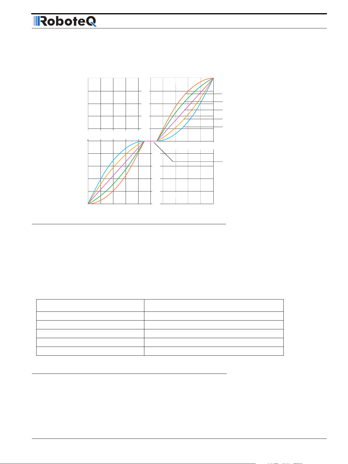
Left / Right Tuning Adjustment
% Forward
(Motor Output)
100
- 60
- 80
- 100
FIGURE 21. Exponentiation curves
The AX2550 is delivered with the “linear” curves selected for both joystick channels. To
select different curves, the user will need to change the values of “E” (channel 1) and “F”
(channel 2) according to the table below. Refer to the chapter “Configuring the Controller
using the Switches” on page 171 or “Using the Roborun Configuration Utility” on page 177
for instructions on how to program parameters into the controller.
- 40
80
60
40
20
- 20
0
20
40
60
80
100
% Reverse
Logarithmic Strong
Logarithmic Weak
Linear (default)
Exponential Weak
Exponential Strong
% Command Input
20
40
60
80
100
Deadband
TABLE 7. Exponent selection table
Exponentiation Parameter Value Selected Curve
E or F = 0 Linear (no exponentiation) - default value
E or F = 1 strong exponential
E or F = 2 normal exponential
E or F = 3 normal logarithmic
E or F = 4 strong logarithmic
Left / Right Tuning Adjustment
By design, DC motors will run more efficiently in one direction than the other. In most situations this is not noticeable. In others, however, it can be an inconvenience. When operating in open loop speed control, the AX2550 can be configured to correct the speed in one
direction versus the other by as much as 10%. Unlike the Joystick center trimming tab that
AX2550 Motor Controller User’s Manual 49
Page 50

General Operation
is found on all R/C transmitters, and which is actually an offset correction, the Left/Right
Adjustment is a true multiplication factor as shown in Figure 22
% Forward
(Motor Output)
100
80
60
40
20
- 20
- 40
- 60
- 80
- 100
0
20
40
60
80
100
% Reverse
20
40
60
% Forward
(Motor Output)
FIGURE 22. Left Right adjustment curves
The curves on the left show how a given forward direction command value will cause the
motor to spin 3 or 5.25% slower than the same command value applied in the reverse
direction. The curves on the right show how the same command applied to the forward
direction will case the motor to spin 3 to 5.25% faster than the same command applied in
the reverse direction. Note that since the motors cannot be made to spin faster than
100%, the reverse direction is the one that is actually slowed down.
80
0%
-3%
-5.25%
% Command Input
100
5.25%
3%
0%
- 100
% Forward
(Motor Output)
100
80
60
40
20
- 20
- 40
- 60
- 80
0
20
40
60
80
100
% Reverse
20
40
60
80
100
In applications where two motors are used in a mixed mode for steering, the Left/Right
Adjustment parameter may be used to make the robot go straight in case of a natural tendency to steer slightly to the left or to the right.
The Left/Right adjustment parameter can be set from -5.25% to +5.25% in seven steps of
0.75%. See “Programmable Parameters List” on page 174 and “Loading, Changing Controller Parameters” on page 181 for details on how to adjust this parameter.
The Left/Right adjustment is performed in addition to the other command curves described
in this section. This adjustment is disabled when the controller operates in any of the supported closed loop modes.
TABLE 8. Left/Right Adjustment Parameter selection
Parameter Value Speed Adjustment Parameter Value Speed Adjustment
7 None (default)
0 -5.25% 8 0.75%
1-4.5%91.5%
2 -3.75% 10 2.25%
3 -3% 11 3%
4 -2.25% 12 3.75%
50 AX2550 Motor Controller User’s Manual Version 1.9b. June 1, 2007
Page 51
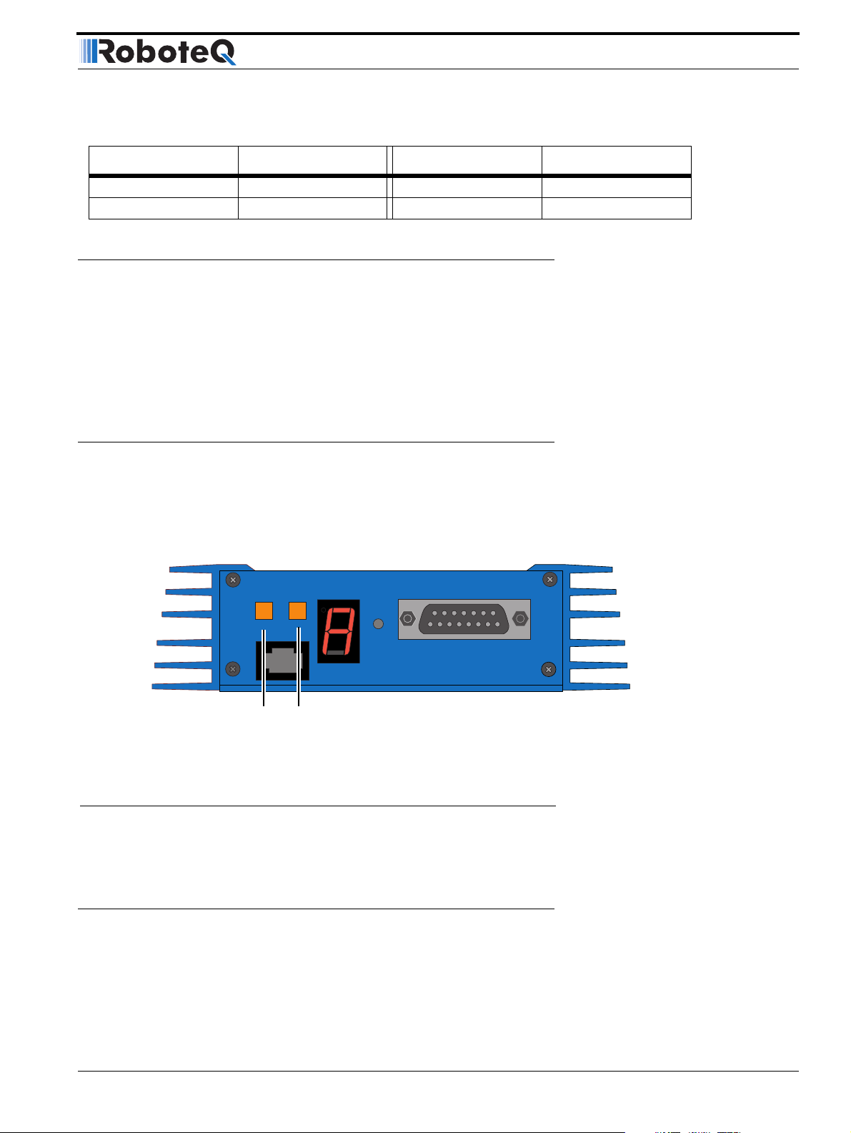
Activating Brake Release or Separate Motor Excitation
TABLE 8. Left/Right Adjustment Parameter selection
Parameter Value Speed Adjustment Parameter Value Speed Adjustment
5 -1.5% 12 4.5%
6 -0.75% 14 5.25%
Activating Brake Release or Separate Motor Excitation
The controller may be configured so that the Output C will turn On whenever one of the
two motors is running. This feature is typically used to activate the mechanical brake
release sometimes found on motors for personal mobility systems. Likewise, this output
can be used to turn on or off the winding that creates the armature’s magnetic field in a
separate excitation motor. This function is disabled by default and may be configured using
the Roborun PC utility. See “Loading, Changing Controller Parameters” on page 181. See
“Connecting devices to Output C” on page 59 for details on how to connect to the output.
Emergency Shut Down Using Controller Switches
In case of emergency, it is possibly to cause the controller to cut off the power to the
motors by depressing the Program and Set buttons simultaneously as shown in the figure
below. The controller will stop immediately without delay.
Program Set
Press the two buttons
simultaneously to cause an
emergency stop
FIGURE 23. Activating an Emergency Stop
After and Emergency Stop condition, the controller must be reset or powered Off
and On to resume normal operation.
Reset
Emergency Stop using External Switch
An external switch can be added to the AX2550 to allow the operator to stop the controller’s output in case of emergency. This controller input can be configured as the “Inverted”
detection instead of Emergency Stop. The factory default for this input is “No Action”.
AX2550 Motor Controller User’s Manual 51
Page 52

General Operation
Inverted Operation
The switch connection is described in “Connecting Switches or Devices to EStop/Invert
Input” on page 62. The switch must be such that it is in the open state in the normal situation and closed to signal an emergency stop command.
After and Emergency Stop condition, the controller must be reset or powered Off
and On to resume normal operation.
For robots that can run upside-down, the controller can be configured to reverse the motor
commands using a gravity activated switch when the robot is flipped. This feature is
enabled only in the mixed mode and when the switch is enabled with the proper configuration of the “Input switch function” parameter. See “Programmable Parameters List” on
page 174.
The switch connection is described in “Connecting Switches or Devices to EStop/Invert
Input” on page 62. The switch must be such that it is in the open state when the robot is in
the normal position and closed when inverted. When the status of the switch has changed,
the controller will wait until the new status has remained stable for 0.5s before acknowledging it and inverting the commands. This delay is to prevent switch activation triggered
by hits and bounces which may cause the controller to erroneously invert the commands.
Special Use of Accessory Digital Inputs
The AX2550 includes two general purpose digital inputs identified as Input E and Input F.
When an Encoder Module is installed, input E is disabled. The location of these inputs on
the DB15 connector can be found in the section “I/O List and Pin Assignment” on
page 58, while the electrical signal needed to activate them is shown on “Connecting
Switches or Devices to Input F” on page 61.
By default, these inputs are ignored by the controller. However, the AX2550 may be configured to cause either of the following actions:
• Activate the buffered Output C
• Turn Off/On the power MOSFET transistors
These alternate modes can only be selected using the Roborun Utility (see “Control Settings” on page 181. Each of these modes is detailed below.
Using the Inputs to Activate the Buffered Output
When this setting is selected, the buffered Output C will be On when the Input line is
pulled to Ground (0V). The Output will be Off when the Input is pulled high.
This function makes it possible to drive solenoids or other accessories up to 2A at 24V
using a very low current switch, for example.
Using the Inputs to turn Off/On the Power MOSFET transistors
When this setting is selected, the controller’s Power MOSFET transistors will be active,
and the controller will be operating normally, only when the input is pulled to ground.
52 AX2550 Motor Controller User’s Manual Version 1.9b. June 1, 2007
Page 53

When the input is pulled high, all the power MOSFETs are turned Off so that the motors
are effectively disconnected from the controller.
This function is typically used to create a “dead man switch” when the controller is driven
using an analog joystick. The motors will be active only while the switch is depressed. If
the switch is left off for any reason, the motors will be disconnected and allowed to freewheel rather than coming to an abrupt stop.
Self-Test Mode
The AX2550 incorporates a simple Self-Test mode that performs the following functions:
The Self Test mode can be conveniently initiated using only the controller’s switches so
that no radio or computer is needed.
To enter the Self Test mode, press and hold the Set button while resetting or powering up
the controller.
Self-Test Mode
• Display the software revision number on the LED display
• Ramp each motor up and down in both directions
• Internal parameters on the serial port output
After a few seconds, the LEDs will display a sequence of two numerical digits and an
optional letter separated by dashes as shown in the examples below.
= Software version 1.9b
FIGURE 25. Press and hold “Set” to display version number and enter self-test
After these digits are displayed, the controller will attempt to power the motors. Motor 1
will be ramped from stop to full speed forward to full speed reverse and back to stop. Then
the same operation will repeat on motor 2. After both motors have completed their ramps,
the software revision will be displayed again and the motors will be ramped again. This
sequence will repeat itself indefinitely until the controller is powered off or reset.
While in the Self Test mode, the AX2550 will continuously send a string of characters on
the RS232 output line. This string will contain 12 or 13 two-digits hexadecimal number representing the 13 following operating parameters.
• Captured R/C Command 1 and 2
• Power Applied to Controller’s output stage
• Values applied to Analog inputs 1 and 2
• Amps on channel 1 and 2
• Internal Heat Sink temperatures 1 and 2
• Main Battery voltage
• Internal 12V voltage
AX2550 Motor Controller User’s Manual 53
Page 54

General Operation
The entire string is repeated every 208 or 224 milliseconds (depending whether the
encoder module is present) with the latest internal parameter values. This information can
be logged using the Roborun Utility (see “Viewing and Logging Data in Analog and R/C
Modes” on page 192).
The string and data format is described in “Analog and R/C Modes Data Logging String For-
mat” on page 166.
Important Warning
Disconnect the Motor Power (thick red wires) from the battery and power the controller by applying 12V on the Power Control input if you do not wish the motors to
be activated while in Self Test mode.
This could be the case if you only wish to use the Self Test sequence to read the software
revision number or to monitor the joystick capture.
• Encoder Speed or Position if module is installed
54 AX2550 Motor Controller User’s Manual Version 1.9b. June 1, 2007
Page 55

AX2550 Connections
SECTION 6 Connecting
Sensors and
Actuators to
Input/Outputs
This section describes the various inputs and outputs and provides guidance on how to
connect sensors, actuators or other accessories to them.
AX2550 Connections
The AX2550 uses a set of power wires (located on the back of the unit) and a DB15 connector for all necessary connections. The diagram on the figure below shows a typical wiring diagram of a mobile robot using the AX2550 controller.
The wires are used for connection to the batteries and motors and will typically carry large
current loads. Details on the controller’s power wiring can be found at “Connecting Power
and Motors to the Controller” on page 29
The DB15 connector is used for all low-voltage, low-current connections to the Radio,
Microcontroller, sensors and accessories. This section covers only the connections to sensors and actuators.
For information on how to connect the R/C radio or the RS232 port, see “R/C Operation”
on page 109 and “Serial (RS-232) Controls and Operation” on page 131.
AX2550 Motor Controller User’s Manual 55
Page 56
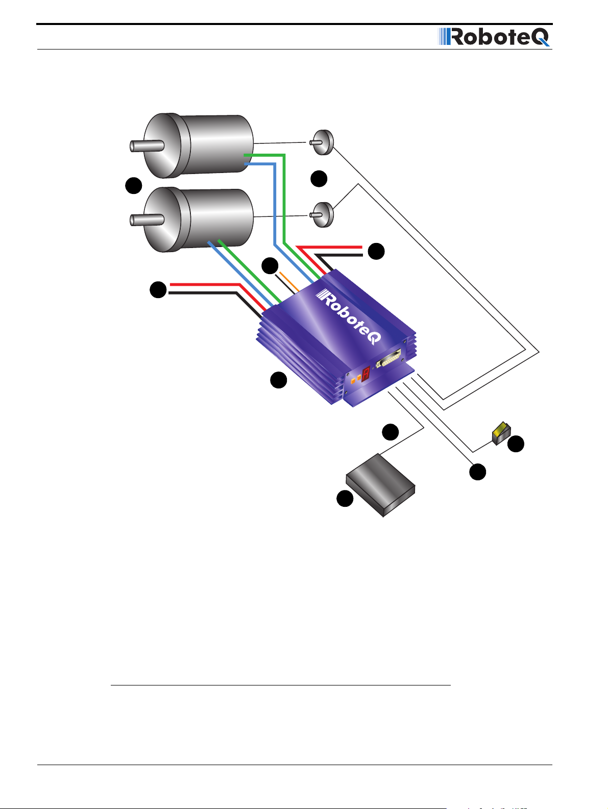
Connecting Sensors and Actuators to Input/Outputs
1
2
3
4
3
t
se
Re
t
e
S
5
t
e
es
R
t
e
S
gram
o
Pr
7
9
8
6
1- DC Motors
2- Optional sensors:
- Tachometers (Closed loop Speed mode)
- Potentiometers (Servo mode)
- Optical Encoder (AX2850 only - all closed
loop modes)
3- Motor Power supply wires
4- Power Control wire
FIGURE 26. Typical controller connections
56 AX2550 Motor Controller User’s Manual Version 1.9b. June 1, 2007
5- Controller
6- R/C Radio Receiver, microcomputer, or
wireless modem
7- Command: RS-232, R/C Pulse
8- Miscellaneous I/O
9- Running Inverted, or emergency stop
switch
Page 57

AX2550’s Inputs and Outputs
AX2550’s Inputs and Outputs
In addition to the RS232 and R/C channel communication lines, the AX2550 includes several inputs and outputs for various sensors and actuators. Depending on the selected operating mode, some of these I/Os provide feedback and/or safety information to the
controller.
When the controller operates in modes that do not use these I/O, these signals become
available for user application. Below is a summary of the available signals and the modes in
which they are used by the controller or available to the user.
TABLE 9. AX2550 IO signals and definitions
Signal I/O type Use Activated
Out C 2A Digital Output User
defined
Inp F Digital Input User
defined
Activate
Output C
Turn FETs
On/Off
Inp E Digital Input Same as Input F - (Not available when encoder module present)
EStop/Invert Digital Input Emer-
gency stop
Invert
Controls
User
defined
Analog In 1 Analog Input Tachome-
ters input
Position
sensing
User
defined
Analog In 2 Analog Input 2 Same as Analog 1 but for Channel 2
Analog In 3 Analog Input 3 Position
sensing
User
defined
Analog In 4 Analog Input 4 Same as Analog 3 but for Channel 4
Activated using R/C channel 3 (R/C mode), or
serial command (RS232 mode)
Activated when any one motor is powered (when
enabled)
Active in RS232 mode only. Read with serial command (RS232)
When Input is configured to drive Output C
When Input is configured as “dead man switch”
input
When Input is configured as Emergency Stop
switch input.
When Input is configured as Invert Controls
switch input.
When input is configured as general purpose.
Read with serial command (RS232).
When Channel 1 is configured in Closed Loop
Speed Control with Analog feedback
When Channel 1 is configured in Closed Loop
Position Control with RC or RS232 command and
Analog feedback
Read value with serial command (RS232).
When Channel 1 is configured in Closed Loop
Position Control with Analog command and Analog feedback
Read value with serial command (RS232).
AX2550 Motor Controller User’s Manual 57
Page 58

Connecting Sensors and Actuators to Input/Outputs
I/O List and Pin Assignment
The figure and table below lists all the inputs and outputs that are available on the AX2550.
9
Pin1
15
8
FIGURE 27. Controller’s DB15 connector pin numbering
TABLE 10. DB15 connector pin assignment
Pin
Number
1 and 9 Output Output C 2A Accessory Output C
2Output
3 Input
4 Input
5 and 13 Power Out Ground Controller ground (-)
6 GND In
Input or
Output
Unused in
RevB Hardware
Signal depending
on Mode Description
R/C: Data Out RS232 Data Logging Output
RS232: Data Out RS232 Data Out
Analog: Data Out RS232 Data Logging Output
R/C: Ch 1 R/C radio Channel 1 pulses
RS232: Data In RS232 Data In (from PC/MCU)
Analog: Unused Unused
R/C: Ch 2 R/C radio Channel 2 pulses
RS232/Analog: Input F Digital Input F readable RS232 mode
Dead man switch activation
Ground
Unused in RevB Hardware
Optocoupler GND Input, Connect to pin 5**
Unused in RevB Hardware
58 AX2550 Motor Controller User’s Manual Version 1.9b. June 1, 2007
Page 59

Connecting devices to Output C
TABLE 10. DB15 connector pin assignment
Pin
Number
7+5V In
8 Digital In
10 Ana l og i n
11 Analog in RC/RS232: Ana in 1 Channel 1 speed or position feedback input
12 RC: Unused
14 Power Out +5V +5V Power Output (100mA max.)
15 Input Input EStop/Inv Emergency Stop or Invert Switch input
Input or
Output
Unused in
RevB Hardware
and Analog
In
Signal depending
on Mode Description
+5V
Unused in RevB Hardware
R/C: Ch 3 R/C radio Channel 3 pulses - (Not available on
RS232: Input E / Ana in 4Accessory input E
Ana: Input E / Ana in 4 Accessory input E
RC/RS232: Ana in 2 Channel 2 speed or position feedback input
Analog: Command 2 Analog command for channel 2
Analog: Command 1 Analog command for channel 1
RS232: Ana in 3 Analog input 3
Ana: Ana in 3 Channel 1 speed or position feedback input in
Optocoupler +5V Input. Connect to pin 14**
Unused in RevB Hardware
AX2850)
Dead man Switch Input
Activate Output C
Analog Input 4 in RevB Hardware
Dead man Switch Input
Activate Output C
Channel 2 speed or position feedback input in
RevB Hardware
RevB Hardware
**These connections should only be done in RS232 mode or R/C mode with radio powered from the controller.
Connecting devices to Output C
Output C is a buffered, Open Drain MOSFET output capable of driving over 2A at up to 24V.
The diagrams on Figure 28 show how to connect a light or a relay to this output:
AX2550 Motor Controller User’s Manual 59
Page 60

Connecting Sensors and Actuators to Input/Outputs
Relay, Valve
Motor, Solenoid
or other Inductive Load
Lights, LEDs, or any other
non-inductive load
+
5 to
24V
DC
-
Output C 1,9
Ground 5
Internal
Transistor
FIGURE 28. Connecting inductive and resistive loads to Output C
This output can be turned On and Off using the Channel 3 Joystick when in the R/C mode.
See “Activating the Accessory Outputs” on page 120 for more information.
When the controller is used in RS232 mode, this output can be turned On and Off using
the !C (On) and !c (Off) command strings. See “Controller Commands and Queries” on
page 138 for more information.
Important warning:
Overvoltage spikes induced by switching inductive loads, such as solenoids or
relays, will destroy the transistor unless a protection diode is used.
5 to
24V
DC
+
-
Output C 1,9
Ground 5
Internal
Transistor
Connecting Switches or Devices to Input E
Input E is a general purpose, digital input. This input is only available if no encoder module
is present and is active when in the RS232 and Analog modes. In R/C mode, this line is
used as the radio channel 3 input.
60 AX2550 Motor Controller User’s Manual Version 1.9b. June 1, 2007
Page 61

Connecting Switches or Devices to Input F
Input E is a high impedance input with a pull-up resistor built into the controller. Therefore
it will report an On state if unconnected, and a simple switch as shown on Figure 29 is necessary to activate it.
+5V Out 14
50kOhm
Input E 8
10kOhm
50kOhm
Ground 5
FIGURE 29. Switch wirings to Input E
The status of Input E can be read in the RS232 mode with the ?i command string. The controller will respond with three sets of 2 digit numbers. The status of Input E is contained in
the first set of numbers and may be 00 to indicate an Off state, or 01 to indicate an On
state.
This input is not available on the AX2850 or on the AX2550 with the Encoder Module
installed.
Remember that, in RevB hardware, InputE is shared with the Analog Input 4. If an analog
sensor is connected, the controller will return a Digital value of 0 if the voltage is lower
than 0.5V and a value of 1 if higher
Connecting Switches or Devices to Input F
Input F is a general purpose digital input. This input is only active when in the RS232 or
Analog modes. In R/C mode, this line is used as the radio channel 2 input.
Internal
Buffer
When left open, Input F is in an undefined stage. As shown in the figure below, a pull down
or pull up resistor must be inserted when used with a single pole switch. The resistor may
be omitted when used with a dual pole switch.
AX2550 Motor Controller User’s Manual 61
Page 62

Connecting Sensors and Actuators to Input/Outputs
On controllers prior to RevB, Input F is an opto-coupled input and requires the buffer to be
powered with a connection between pin 14 and 7, and between 13 and 6, to operate.This
power connection in not needed on RevB hardware.
+5V Out 14
+5V Out 14
+5V Out 14
+5V Out 14
+5V In 7
+5V In 7
+5V In 7
10kOhm
10kOhm
10kOhm
10kOhm
+5V In 7
Input F 4
Input F 4
Input F 4
Input F 4
GND In 6
GND In 6
GND In 6
GND In 6
GND Out 5
GND Out 5
GND Out 5
GND Out 5
10kOhm
10kOhm
10kOhm
10kOhm
Internal
Internal
Internal
Internal
Buffer
Buffer
Buffer
Buffer
FIGURE 30. Switch wiring to Input F
The status of Input F can be read in the RS232 mode with the ?i command string. The controller will respond with three sets of 2 digit numbers. The status of Input F is contained in
the second set of numbers and may be 00 to indicate an Off state, or 01 to indicate an On
state.
10kOhm
10kOhm
+5V Out 14
+5V Out 14
+5V Out 14
+5V In 7
+5V In 7
+5V In 7
Input F 4
Input F 4
Input F 4
GND In 6
GND In 6
GND In 6
GND Out 5
GND Out 5
GND Out 5
10kOhm
10kOhm
10kOhm
Internal
Internal
Internal
Buffer
Buffer
Buffer
Connecting Switches or Devices to EStop/Invert Input
This input is used to connect various switches or devices depending on the selected controller configuration.
The factory default for this input is “No Action”.
This input can also be configured to be used with an optional “inverted” sensor switch.
When activated, this will cause the controls to be inverted so that the robot may be driven
upside-down.
When neither Emergency Stop or Inverted modes are selected, this input becomes a general purpose input like the other two described above.
This input is a high impedance input with a pull-up resistor built into the controller. Therefore it will report an On state (no emergency stop, or not inverted) if unconnected. A simple switch as shown on Figure 31 is necessary to activate it. Note that to trigger an
Emergency Stop, or to detect robot inversion this input must be pulled to ground.
Figure 31 show how to wire the switch to this input.
62 AX2550 Motor Controller User’s Manual Version 1.9b. June 1, 2007
Page 63

Analog Inputs
+5V 14
Input
EStop/Inv 15
Ground 5
FIGURE 31. Emergency Stop / Invert switch wiring
The status of the EStop/Inv can be read at all times in the RS232 mode with the ?i com-
mand string. The controller will respond with three sets of 2 digit numbers. The status of
the ES/Inv Input is contained in the last set of numbers and may be 00 to indicate an Off
state, or 01 to indicate an On state.
AX2500 Internal
Buffer and Resistor
10kOh m
Analog Inputs
The controller has (2 on pre-RevB hardware) 4 Analog Inputs that can be used to connect
position, speed, temperature, voltage or most other types of analog sensors. These inputs
can be read at any time using the ?p query for Analog inputs 1 and 2 and the ?r query for
Inputs 3 and 4. The following section show the various uses for these inputs.
Connecting Position Potentiometers to Analog Inputs
When configured in the Position mode, the controller’s analog inputs are used to obtain
position information from a potentiometer coupled to the motor axle. This feature is useful
in order to create very powerful servos as proposed in the figure below:
Position Feedback
Potentiometer
Gear box
FIGURE 32. Motor and potentiometer assembly for position servo operation
AX2550 Motor Controller User’s Manual 63
Page 64

Connecting Sensors and Actuators to Input/Outputs
Connecting the potentiometer to the controller is as simple as shown in the diagram on
Figure 33.
+5V 14
Ana 1: 11
Ana 2: 10
Ana 3: 12
Ana 4: 8
10kOhm
Ground 5
FIGURE 33. Potentiometer wiring in Position mode
The potentiometer must be attached to the motor frame so that its body does not move in
relationship with the motor. The potentiometer axle must be firmly connected to the gear
box output shaft. The gearbox must be as tight as possible so that rotation of the motor
translates into direct changes to the potentiometers, without slack, at the gearbox’s out-
put.
Internal Resistors
and Converter
47kOhm
10kOhm
47kOhm
A/D
TABLE 11. Analog Position Sensor connection depending on operating mode
Operating Mode
Ana 1
pin 11
Ana2
pin 10
Ana 3
pin 12
Ana 4
pin 8
RC or RS232 - Dual Channel Position 1 Position 2 Unused Unused
Analog - Dual Channel Command 1 Command 2 Position 1 Position 2
RC or RS232 - Single Channel Position Unused Unused Unused
RC or RS232 - Dual Channel Command Unused Position Unused
See “Closed Loop Position Mode” on page 85 for complete details on Position Mode wir-
ing and operation.
Important Warning
Beware that the wrong + and - polarity on the potentiometer will cause the motor to
turn in the wrong direction and not stop. The best method to figure out the right
potentiometer is try one way and change the polarity if incorrect. Note that while
you are doing these tests, the potentiometer must be loosely attached to the
motor’s axle so that it will not be forced and broken by the motor’s uncontrolled
rotation in case it was wired wrong.
Connecting Tachometer to Analog Inputs
When operating in closed loop speed mode, tachometers must be connected to the controller to report the measured motor speed. The tachometer can be a good quality brushed
DC motor used as a generator. The tachometer shaft must be directly tied to that of the
motor with the least possible slack.
64 AX2550 Motor Controller User’s Manual Version 1.9b. June 1, 2007
Page 65
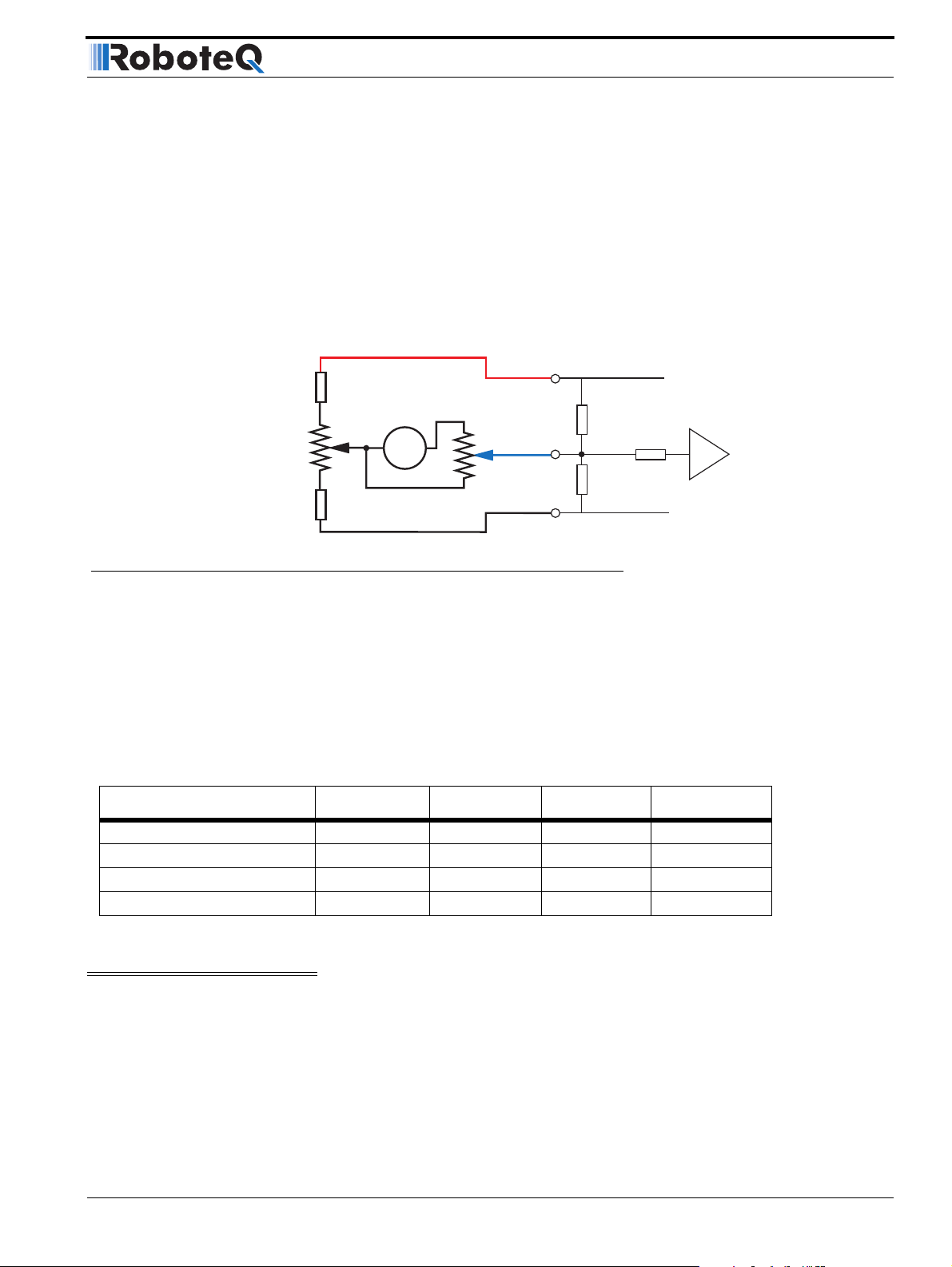
Connecting Tachometer to Analog Inputs
Since the controller only accepts a 0 to 5V positive voltage as its input, the circuit shown in
Figure 34 must be used between the controller and the tachometer: a 10kOhm potentiometer is used to scale the tachometer output voltage to -2.5V (max reverse speed) and
+2.5V (max forward speed). The two 1kOhm resistors form a voltage divider that sets the
idle voltage at mid-point (2.5V), which is interpreted as the zero position by the controller.
The voltage divider resistors should be of 1% tolerance or better. To precisely adjust the
2.5V midpoint value it is recommended to add a 100 ohm trimmer on the voltage divider.
With this circuitry, the controller will see 2.5V at its input when the tachometer is stopped,
0V when running in full reverse, and +5V in full forward.
+5V 14
1kOhm
Zero Adjust
100 Ohm pot
1kOhm
Max Speed Adjust
10kOhm pot
Ta c h
Ana 1: 11
Ana 2: 10
Ana 3: 12
Ana 4: 8
Ground 5
Internal Resistors
and Converter
47kOhm
A/D
10kOhm
47kOhm
FIGURE 34. Tachometer wiring diagram
The tachometers can generate voltages in excess of 2.5 volts at full speed. It is important,
therefore, to set the potentiometer to the minimum value (cursor all the way down per this
drawing) during the first installation.
Since in closed loop control the measured speed is the basis for the controller’s power out-
put (i.e. deliver more power if slower than desired speed, less if higher), an adjustment and
calibration phase is necessary. This procedure is described in “Closed Loop Speed Mode”
on page 97.
TABLE 12. Analog Speed Sensor connection depending on operating mode
Operating Mode Ana 1 (p11) Ana2 (p10) Ana 3 (p12) Ana 4 (p8)
RC or RS232 - Dual Channel Speed 1 Speed 2 Unused Unused
Analog - Dual Channel Command 1 Command 2 Speed 1 Speed 2
RC or RS232 - Single Channel Speed Unused Unused Unused
RC or RS232 - Dual Channel Command Unused Speed Unused
Important Warning
The tachometer’s polarity must be such that a positive voltage is generated to the
controller’s input when the motor is rotating in the forward direction. If the polarity
is inverted, this will cause the motor to run away to the maximum speed as soon as
the controller is powered with no way of stopping it other than pressing the emergency stop button or disconnecting the power.
AX2550 Motor Controller User’s Manual 65
Page 66

Connecting Sensors and Actuators to Input/Outputs
Connecting External Thermistor to Analog Inputs
Using external thermistors, the AX2550 can be made to supervise the motor’s tempera-
ture and adjust the power output in case of overheating. Connecting thermistors is done
according to the diagram show in Figure 35. The AX2550 is calibrated using a 10kOhm
Negative Coefficient Thermistor (NTC) with the temperature/resistance characteristics
shown in the table below.
TABLE 13. Recommended NTC characteristics
Temp (oC) -25 0 25 50 75 100
Resistance (kOhm) 86.39 27.28 10.00 4.16 1.92 0.93
+5V 14
Ana 1: 11
10kOhm
10kOhm
NTC
Thermistor
Ana 2: 10
Ana 3: 12
Ana 4: 8
47kOhm
47kOhm
Internal Resistors
and Converter
A/D
10kOhm
Ground 5
FIGURE 35. NTC Thermistor wiring diagram
Thermistors are non-linear devices. Using the circuit described on Figure 35, the controller
will read the following values (represented in signed binary) according to the temperature.
100
50
0
-50
Analog Input Reading
-100
-150
-20
0
10
20
30
40
50
-10
Temperature in Degrees C
60
FIGURE 36. Signed binary reading by controller vs. NTC temperature
70
80
90
100
110
66 AX2550 Motor Controller User’s Manual Version 1.9b. June 1, 2007
Page 67
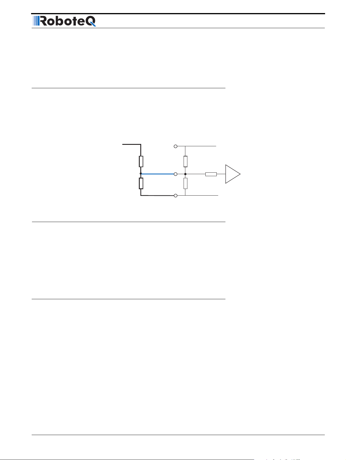
Using the Analog Inputs to Monitor External Voltages
To read the temperature, use the ?p command to have the controller return the A/D converter’s value. The value is a signed 8-bit hexadecimal value. Use the chart data to convert
the raw reading into a temperature value.
Using the Analog Inputs to Monitor External Voltages
The analog inputs may also be used to monitor the battery level or any other DC voltage. In
this mode, the controller does not use the voltage information but merely makes it available to the host microcomputer via the RS232 port. The recommended schematic is
shown in Figure 37.
To Battery
+ Terminal
47kOhm
4.7kOhm
+5V 14
Ana 1: 11
Ana 2: 10
Ana 3: 12
Ana 4: 8
Ground 5
FIGURE 37. Battery voltage monitoring circuit
Using these resistor values, it is possible to measure a voltage ranging from -5V to +60V
with a 0.25V resolution. The formula for converting the A/D reading into a voltage value is
as follows.
Measured volts = ((controller reading + 128) * 0.255) -5
Note: The A/D converter’s reading is returned by the ?p command and is a signed 8-bit
hexadecimal value. You must add 128 to bring its range from -127/+127 to 0/255.
Connecting User Devices to Analog Inputs
Internal Resistors
and Converter
47kOhm
A/D
10kOhm
47kOhm
The two analog inputs can be used for any other purpose. The equivalent circuit for each
input is shown in Figure 38. The converter operates with an 8-bit resolution, reporting a
value of 0 at 0V and 255 at +5V. Care should be taken that the input voltage is always positive and does not exceed 5V. The converter’s intrinsic diodes will clip any negative voltage
or voltage above 5V, thus providing limited protection. The value of the analog inputs can
be read through the controller’s RS232 port.
AX2550 Motor Controller User’s Manual 67
Page 68
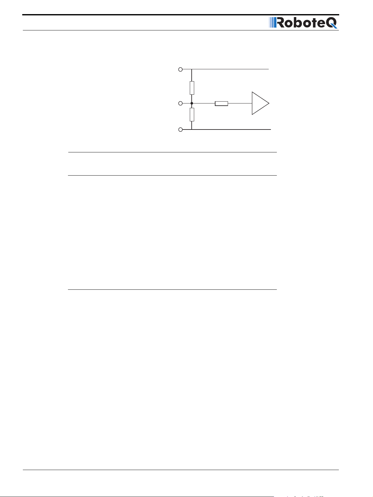
Connecting Sensors and Actuators to Input/Outputs
+5V 14
Ana 1: 11
Ana 2: 10
Ana 3: 12
Ana 4: 8
Ground 5
47kOhm
47kOhm
FIGURE 38. AX2550 Analog Input equivalent circuit
Internal Voltage Monitoring Sensors
The AX2550 incorporates voltage sensors that monitor the Main Battery voltage and the
Internal 12V supply. This information is used by the controller to protect it against overvoltage and undervoltage conditions (see “Overvoltage Protection” on page 38 and “Under-
voltage Protection” on page 38). These voltages can also be read from the RS232 serial
port using the ?e query.
The returned value are numbers ranging from 0 to 255. To convert these numbers into a
Voltage figure, the following formulas must be used:
Measured Main Battery Volts = 55 * Read Value / 256
Measured Internal Volts = 28.5 * Read Value / 256
A/D
10kOhm
Internal Heatsink Temperature Sensors
The AX2550 includes temperature sensors making contact with the each of the two Heatsink sides of the controller.
These sensors are used to automatically reduce the maximum Amps that the controller
can deliver as it overheats. However, the temperature can be read using the RS232 port
using the ?m query, or during data logging (see “Analog and R/C Modes Data Logging
String Format” on page 166)
The analog value that is reported will range from 0 (warmest) to 255 (coldest). Because of
the non-linear characteristics of NTC thermistors, the conversion from measured value to
temperature must be done using the correction curve below.
It should be noted that the temperature is measured inside the controller and that it may
be temporarily be different than the temperature measured outside the case.
68 AX2550 Motor Controller User’s Manual Version 1.9b. June 1, 2007
Page 69
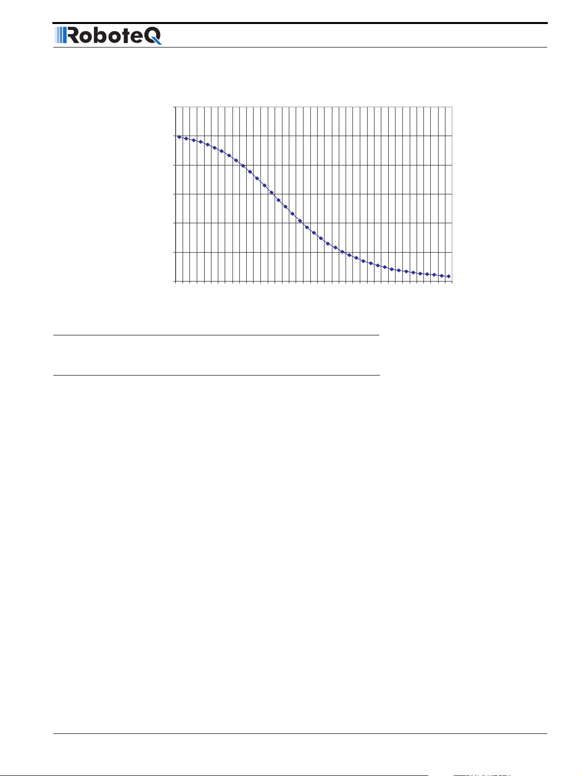
Temperature Conversion C Source Code
300
250
200
150
100
Reported Analog Value
50
0
-40
-30
-20
-10
0
10
20
30
40
50
60
70
80
90
100
110
120
130
140
150
Temperature in Degrees C
FIGURE 39. Analog reading by controller vs. internal heat sink temperature
Temperature Conversion C Source Code
The code below can be used to convert the analog reading into temperature. It is provided
for reference only. Interpolation table is for the internal thermistors.
int ValToHSTemp(int AnaValue)
{
// Interpolation table. Analog readings at -40 to 150 oC, in 5o intervals
int TempTable[39] ={248, 246, 243, 240, 235, 230, 224, 217, 208, 199, 188, 177,
165, 153, 140, 128, 116, 104,93, 83, 74, 65, 58, 51, 45, 40, 35, 31, 27, 24, 21,
19, 17, 15, 13, 12, 11, 9, 8};
int LoTemp, HiTemp, lobound, hibound, temp, i;
i=38;
while (TempTable[i] < AnaValue &&i>0)
i--;
if (i < 0)
i=0;
if (i == 38)
return 150;
else
{
LoTemp =i*5-40;
HiTemp = LoTemp + 5;
lobound = TempTable[i];
hibound = TempTable[i+1];
temp = LoTemp + (5 * ((AnaValue - lobound)*100/ (hibound - lobound)))/100;
return temp;
}
}
AX2550 Motor Controller User’s Manual 69
Page 70

Connecting Sensors and Actuators to Input/Outputs
70 AX2550 Motor Controller User’s Manual Version 1.9b. June 1, 2007
Page 71

Optical Incremental Encoders Overview
SECTION 7 Installing,
Connecting and
Using the
Encoder Module
This section describes the Encoder input module that is factory installed inside the AX2850
or that may be added onto the AX2550.
Optical Incremental Encoders Overview
Optical incremental encoders are a means for capturing speed and travelled distance on a
motor. Unlike absolute encoders which give out a multi-bit number (depending on the resolution), incremental encoders output pulses as they rotate. Counting the pulses tells the
application how many revolutions, or fractions of, the motor has turned. Rotation velocity
can be determined from the time interval between pulses or by the number of pulses
within a given time period. Because they are digital devices, incremental encoders will
measure distance and speed with perfect accuracy.
Since motors can move in forward and reverse directions, it is necessary to differentiate
the manner that pulses are counted so that they can increment or decrement a position
counter in the application. Quadrature encoders have dual channels, A and B, which are
electrically phased 90° apart. Thus, direction of rotation can be determined by monitoring
the phase relationship between the two channels. In addition, with a dual-channel encoder,
a four-time multiplication of resolution can be achieved by counting the rising and falling
edges of each channel (A and B). For example, an encoder that produces 250 Pulses per
Revolution (PPR) can generate 1,000 Counts per Revolution (CPR) after quadrature.
AX2550 Motor Controller User’s Manual 71
Page 72
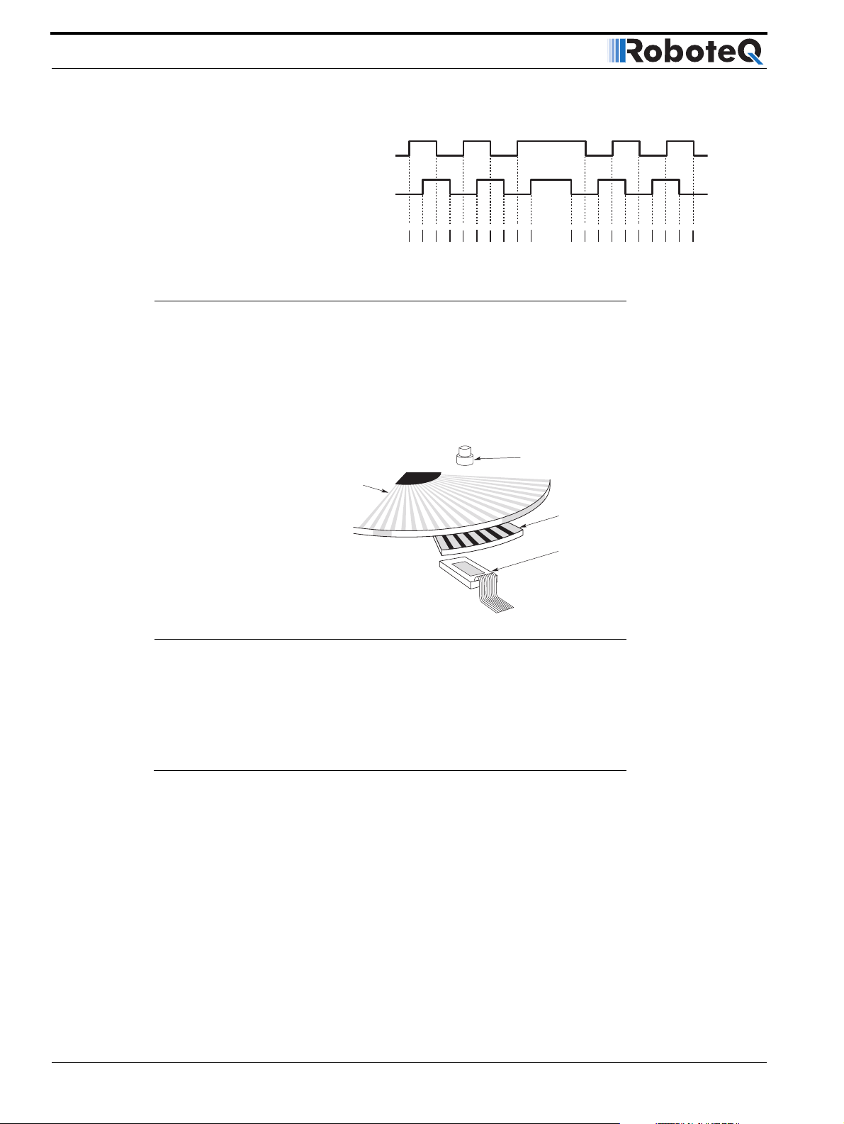
Installing, Connecting and Using the Encoder Mod-
A Channel
1 Pulse
= 4 Transitions
B Channel
= 4 Counts
Quadrature
Signal
FIGURE 40. Quadrature encoder output waveform
The figure below shows the typical construction of a quadrature encoder. As the disk
rotates in front of the stationary mask, it shutters light from the LED. The light that passes
through the mask is received by the photo detectors. Two photo detectors are placed side
by side at so that the light making it through the mask hits one detector after the other to
produces the 90o phased pulses.
Count Up
Count Down
LED light source
Rotating
encoder disk
FIGURE 41. Typical quadrature encoder construction
Unlike absolute encoders, incremental encoders have no retention of absolute position
upon power loss. When used in positioning applications, the controller must move the
motor until a limit switch is reached. This position is then used as the zero reference for all
subsequent moves.
Recommended Encoder Types
The module may be used with most incremental encoder module as long as they include
the following features:
• Two quadrature outputs (Ch A, Ch B), single ended signal
• 2.5V minimum swing between 0 Level and 1 Level on quadrature output
• 5VDC operation. 100mA or less current consumption per encoder
Stationary mask
Photodetector
More sophisticated incremental encoders with differential outputs, index, and other features may be used, however these additional capabilities will be ignored.
The choice of encoder resolution is very wide and is constrained by the module’s maxi-
mum pulse count at the high end and measurement resolution for speed at the low end.
72 AX2550 Motor Controller User’s Manual Version 1.9b. June 1, 2007
Page 73
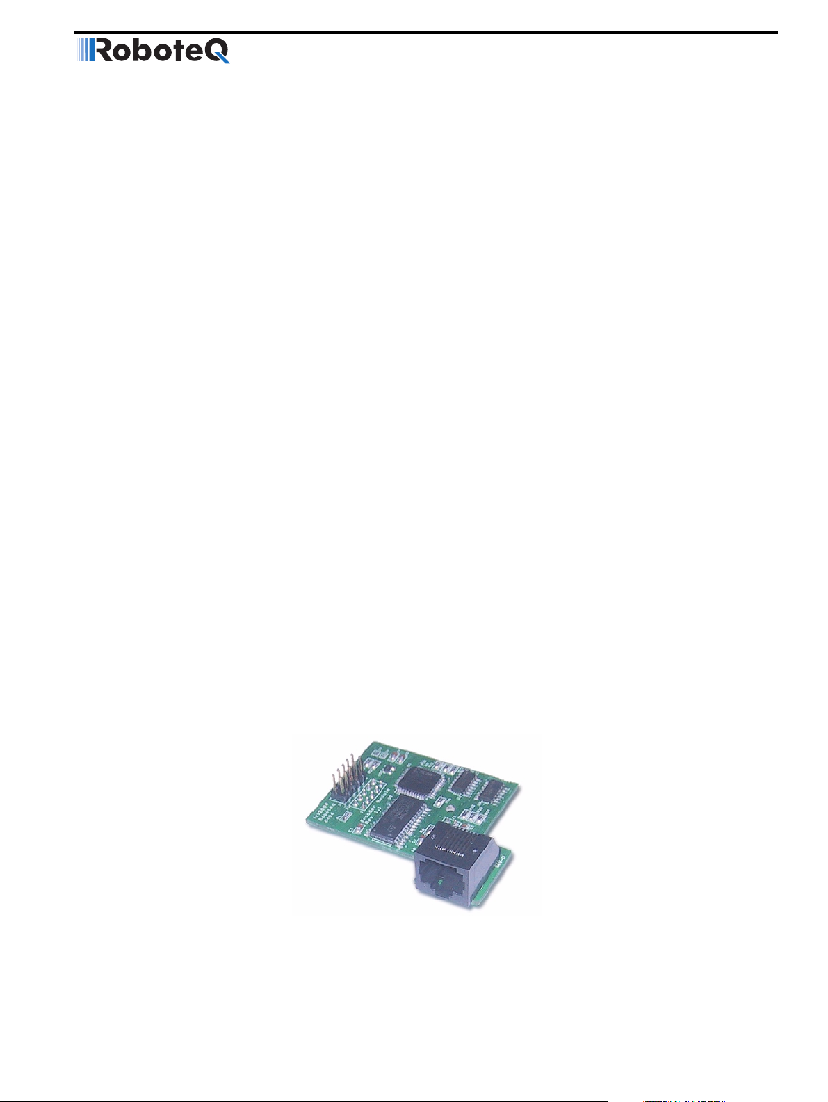
Installing the Encoder Module
Specifically, the encoder module can process 250,000 counts per seconds. As discussed
in the previous section, a count is generated for each transition on the Channel A and
Channel B. Therefore the module will work with encoders outputting up to 62,500 pulses
per second.
Commercial encoders are rated by their numbers of “Pulses per Revolution” (also sometimes referred as “Cycles per Revolution). Carefully read the manufacturer’s datasheet to
understand whether this number represents the number of pulses that are output by each
channel during the course of a 360o revolution rather than the total number of transitions
on both channels during a 360o revolution. The second number is 4 times larger than the
first one.
The formula below gives the pulse frequency at a given RPM and encoder resolution in
Pulses per Revolution.
Pulse Frequency in Hz = RPM / 60 * PPR * 4
Example: a motor spinning at 10,000 RPM max, with an encoder with 200 Pulses per Revolution would generate:
10,000 / 60 * 200 * 4 = 133.3 kHz which is well within the 250kHz maximum supported by
the encoder module.
An encoder with a 200 Pulses per Revolutions is a good choice for most applications.
A higher resolution will cause the counter to count faster than necessary and possibly
reach the encoder module’s maximum frequency limit.
An encoder with a much lower resolution will cause speed to be measured with less precision.
Installing the Encoder Module
The Encoder module is available in kit form for installation by the user inside the AX2550
controller. It may also be ordered factory-installed in the controller by using the product reference AX2850.
FIGURE 42. Encoder Module for AX2550. Factory installed in AX2850
AX2550 Motor Controller User’s Manual 73
Page 74

Installing, Connecting and Using the Encoder Mod-
Follow these simple steps to install:
1- With the power removed, remove the controller’s face plate and slide off the cover.
2- Carefully insert the encoder module on top of the two headers present on the controller’s main board and shown in Figure 43. Beware that the two matting connectors are precisely aligned.
FIGURE 43. Position of Encoder Module on Controller’s main board
3- The encoder module will be held in place by the connectors and the new front bracket’s
opening around the RJ11 connector. For added stability, place the foam pad on top of the
Encoder module as shown in Figure 44 so that it is held in place by the sliding cover. For
use in harsh shock and vibration environments, you may instead solder a metal wire inside
the 0.1” hole found on the main board (next to one of the two header) and solder the other
en inside the matching hole on the encoder module, as shown on Figure 45.
Cover
Place Foam Block on Encoder module
Encoder Module
Main Board
FIGURE 44. Place foam block between module and cover to hold in place
74 AX2550 Motor Controller User’s Manual Version 1.9b. June 1, 2007
Page 75

Connecting the Encoder
FIGURE 45. Solder wire for robust assembly
4- Slide the cover back on. Install the new face plate.
Connecting the Encoder
The Encoder module uses a widely available 8-pin RJ45 connector identical to those found
on all Ethernet devices. The connector provides 5V power to the encoders and has inputs
for the two quadrature signals from each encoder. Using multi-level signaling, it is also possible to share the quadrature inputs with limit switches. The figure and table below
describe the connector and its pin assignment.
Encoder Module
Solder wire
Main Board
1
8
8
1
FIGURE 46. Encoder connector
TABLE 14. Encoder Connector Pinout
Cable Color
Pin Name
(when using standard network cable)
1 Encoder 2 - Channel B. Optional Limit Switch 4 Orange/White
2 Encoder 2 - Channel A. Optional Limit Switch 3 Orange
3 Ground (same as pin 7) Green/White
4 5V Out (same as pin 8) Blue
5 Encoder 1 - Channel B. Optional Limit Switch 2 Blue/White
6 Encoder 1 - Channel A. Optional Limit Switch 1 Green
7 Ground (same as pin 3) Brown/White
8 5V Out (same as pin 4) Brown
AX2550 Motor Controller User’s Manual 75
Page 76

Installing, Connecting and Using the Encoder Mod-
Cable Length and Noise Considerations
Cable should not exceed one 3’ (one meter) to avoid electrical noise to be captured by the
wiring. A ferrite core filter must be used for length beyond 2’ (60 cm). For longer cable
length use an oscilloscope to verify signal integrity on each of the pulse channels and on
the power supply.
Ferrite Core
FIGURE 47. Use ferrite core on cable length beyond 2’ or 60cm
Important Warning
Excessive cable length will cause electrical noise to be captured by the controller and
cause erratic functioning that may lead to failure. In such situation, stop operation
immediately.
Motor - Encoder Polarity Matching
When using the Encoder module for closed loop speed control, it is imperative that when
the motor is turning in the forward direction, the counter increments its value and a positive speed value is measured.
Encoder
Using the PC utility, it is possible to exercise the motors and view the encoder readings.
See “Encoder Testing and Setting Using the PC Utility” on page 83.
If the Encoder counts backwards when the motor moves forward, correct this by either:
1- Swapping Channel A and Channel B on the encoder connector. This will cause the
encoder module to reverse the count direction, or
2- Swapping the leads on the motor. This will cause the motor to rotate in the opposite
direction.
Voltage Levels, Thresholds and Limit Switches
The encoder module’s input uses a comparator to reshape the encoder’s output signal. If
the signal is below a programmable threshold level, then it is considered to be 0. If above,
it is considered to be 1. The output of this comparator feeds the quadrature detector and
counters.
76 AX2550 Motor Controller User’s Manual Version 1.9b. June 1, 2007
Page 77

Voltage Levels, Thresholds and Limit Switches
On the 2850 family of controllers, the threshold voltage may be changed under software
control to any value between 0 and 5V in order to meet unusual encoder specifications. By
default, the threshold level is 2.5V.
Another set of comparators on the same input signals detects pulses that are above and
below a fixed 0.5V threshold. Using a special circuitry for creating multi-level signaling (see
next section below), the output of these comparators serves to detect the status of
optional limit switches.
Figure 49 and Figure 48 show the conditioned signals as seen by the encoder.
In Figure 49, the encoders are connected directly to the Channel A and B inputs. In this
case, it will cause a Switch Detection condition because the encoder’s 0 level is below
0.5V, which should be ignored.
Signal on Channel A or B
Quadrature Signal
Switch Detect Signal
(Not meaningful)
FIGURE 48. Signals seen by encoder using direct connection and no limit switches
In Figure 48, the encoder and switches are wired to the encoder module using a set of
resistors designed to create a multi-level signal combining both pieces of information.
Details on the necessary wiring is provided in the next section.
Since the encoder output signal is “shifted-up” by a few volts, it always stays above the
Limit Switch comparator’s threshold, and no Switch Detection condition is generated.
However, since the limit switches connect to ground when On, the level will dip below the
0.5V and generate a Switch Detection condition.
Signal on Channel A or B
2.5V
0.5V
2.5V
0.5V
Quadrature Signal
Switch Detect Signal
FIGURE 49. Signals seen by encoder using multi-levels and limit switches
AX2550 Motor Controller User’s Manual 77
Page 78

Installing, Connecting and Using the Encoder Mod-
Important Warning
When a limit switch is activated, the encoder signal that is shared with the switch is
no longer visible by the encoder module, and pulse counting and speed measurement stops.
Wiring Optional Limit Switches
If limit switches are needed by the application, additional circuitry is required in order to
create a multi-level signal that shares the encoder and the switch information. The figure
below shows the electrical diagram of the required wiring.
4.7kOhm
5V Out
4.7kOhm
5V
GND
1kOhm
Ch A
Encoder
Ch B
1kOhm
SW1
Ch A In
Ch B In
SW2
GND
FIGURE 50. Signals seen by encoder using multi-levels and limit switches
Using this circuit when the switch is open, a 0V (low-level) output from the encoder goes
through a 1k and 4.7k voltage divider, thus creating a voltage that will never be below 0.8V
at the encoder module’s input.
When the switch is activated, the module’s input is pulled to 0V.
It is recommended that a voltmeter and/or oscilloscope be used to verify that the right voltage levels are created as the encoder rotates and the switches activate.
Encoder Module
You may also use the Encoder setup/test function in the Roborun utility (see “Encoder
Testing and Setting Using the PC Utility” on page 83). If the wiring is correct, the counters
should increment/decrement as the motor rotate. The switch indicators should be always
off unless the switches are actually activated.
78 AX2550 Motor Controller User’s Manual Version 1.9b. June 1, 2007
Page 79

Wiring Limit Switches Without Encoders
Wiring Limit Switches Without Encoders
If no encoder is used, the Encoder Module’s inputs can be used to wire limit switches
directly with solely a pull-up resistor as shown in the diagram below.
5V Out
4.7kOhm
SW1
4.7kOhm
SW2
4.7kOhm
SW3
4.7kOhm
Ch B In
Ch A In
Ch B In
Ch A In
SW4
FIGURE 51. Signals seen by encoder using multi-levels and limit switches
Effect of Limit Switches
Each pair of limit switches will stop the motion of a given motor in a given direction. This
will have the effect of stopping the motor when a limit is reached while allowing motion in
the other direction, away for that limit.
GND
8 - 4
5
6
1
Encoder Input
2
7 - 3
TABLE 15. Effects of Limit Switches 1 and 2 on Motor 1
SW1 SW2 Motor 1 Fwd Motor 1 Rev
OFF OFF Allowed Allowed
ON OFF Stopped Allowed
OFF ON Allowed Stopped
ON ON Stopped Stopped
TABLE 16. Effects of Limit Switches 3 and 4 on Motor 2
SW3 SW4 Motor 2 Fwd Motor 2 Rev
OFF OFF Allowed Allowed
ON OFF Stopped Allowed
AX2550 Motor Controller User’s Manual 79
Page 80

Installing, Connecting and Using the Encoder Mod-
TABLE 16. Effects of Limit Switches 3 and 4 on Motor 2
SW3 SW4 Motor 2 Fwd Motor 2 Rev
OFF ON Allowed Stopped
ON ON Stopped Stopped
In Single Channel Mode, limit switches 3 and 4 are used. This is to allow direct connection
of an encoder on the inputs for channel 1 and direct connection of switches on the inputs
for channel 2
TABLE 17. Effects of Limit Switches 3 and 4 on Motor 2 in Single Channel Configuration
SW3 SW4 Motor Fwd Motor Rev
OFF OFF Allowed Allowed
ON OFF Stopped Allowed
OFF ON Allowed Stopped
ON ON Stopped Stopped
Using the Encoder Module to Measure Distance
As the encoders rotate, their quadrature outputs is automatically processed and increments/decrements two 32-bit counter inside the Encoder Module. There is one 32-bit
counter for each of the encoders.
The counter values are stored as a signed binary numbers, ranging from -2,147,836,648 to
+2,147,836,647 (Hexadecimal format of value 80000000 to 7FFFFFFF respectively. When
the maximum or minimum counter values are reached, the counters automatically roll over
to zero.
The counters can be read and set using the commands described in “The Encoder Module
contains its own Microcontroller and firmware in Flash. When present, it responds to a
large set of dedicated commands and queries via the controller’s serial port. See “RS232
Encoder Command Set” on page 155.” on page 82.
Using the Encoder to Measure Speed
The encoder module will automatically compute rotation speed for each encoder. The
resulting measured speed is a value ranging from 0 to + 127 and 0 to -127, where 127 represent a relative ratio of a maximum speed value chosen by the user.
For example, if the encoder module is configured so that the highest measured speed
value is 3,000 RPM, then a reading of 63 (127/2) would be 1,500 RPM.
The relationship between the measured speed and the actual speed is a factor of two variable parameters: a Time Based period value stored inside the Encoder module and the
Encoder’s number of Pulses per Revolution. Note: the Encoder’s number of Pulses per
Revolution is not stored in the controller.
The Time Base is a number of 256us time intervals between two counter reads.
80 AX2550 Motor Controller User’s Manual Version 1.9b. June 1, 2007
Page 81

Using the Encoder to Track Position
A simple procedure is included in the Roborun PC utility to easily determine and set these
parameters.
For information, the exact formula is shown below:
Measured Speed Value = RPM * PPR * 4 * (Time Base+1) * 256 / (60 * 1000000)
or Measured Speed Value = RPM * PPR * (Time Base + 1) / 58593.75
Example: a motor spinning at 1,000 RPM, with an encoder with 200 Pulses per Revolution,
and a Time Base set at 4 will produce the following measurement:
1000 *200 * (4 + 1) / 58593.75 = 17
The same formula modified to show the actual RPM at a given Measure Speed Value is as
follows:
RPM = Measured Speed Value * 60 * 1000000 / (PPR * 4 * 256 * (Time Base+1))
or RPM = Measured Speed Value * 58593.75 /((Time Base + 1) * PPR)
In our example, a measured speed value of 127 corresponds to the following measurable
max actual RPM values.
RPM at Max Measurable Speed Value = 127 * 58593.75 / ((4 + 1) * 200) = 7441 RPM
A measured speed value of 1 corresponds to the following measurable min. actual RPM
values.
RPM at Min. Measurable Speed Value = 1 * 58593.75 / ((4 + 1) * 200) = 58.6 RPM
The Roborun Utility automatically makes the above calculations when setting up the
encoder.
Important Notice
The time base value should not exceed 63 so that a new speed value can be measured at every 16ms loop. The roborun utility automatically limits the time base
value that can be entered.
Using the Encoder to Track Position
The encoder module can be used to report the distance between the actual motor position
and a desired destination. The resulting measured “distance” can then be used by the con-
troller in the position mode to move the motor in the right direction until the destination is
reached. This movement is controlled by the PID position algorithm inside the controller
and is therefore best suited at tracking position.
Since the controller uses a signed 8-bit value (-127 to +127) for the distance measurement
in the Position Mode, a special algorithm is used to convert the real distance which can be
much higher than -127 to +127, as both the counter and destination registers are 32-bit
wide.
AX2550 Motor Controller User’s Manual 81
Page 82
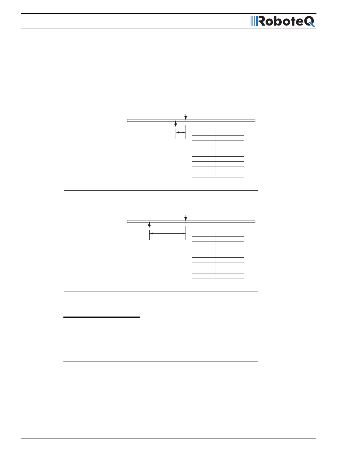
Installing, Connecting and Using the Encoder Mod-
The actual formula is as follows:
Distance = (Destination - Counter value) / Divider
Where: divider is a configurable parameter of value 1, 2, 4, 8, 16, 32, 64 or 127
If computed distance is less than -127, then reported distance is -127
If computed distance is larger than +127, then reported distance is +127
Counter= 50,000
FIGURE 52. Small distance computation example
Destination= 50,050
distance at divider
50 1
25 2
12 4
6 8
3 16
1 32
0 64
0 128
Destination= 50,000
Counter= 45,000
distance at divider
127 1
127 2
127 4
127 8
127 16
127 32
78 64
39 128
FIGURE 53. Large distance computation example
Important Notice
Encoders do not report an absolute position value but a count that is relative to the
point where the motor shaft was at power up. It is typically necessary to have the
motors moved to a “home” position and reset the counters at that reference point.
RS232 Communication with the Encoder Module
The Encoder Module contains its own Microcontroller and firmware in Flash. When
present, it responds to a large set of dedicated commands and queries via the controller’s
serial port. See “RS232 Encoder Command Set” on page 155.
82 AX2550 Motor Controller User’s Manual Version 1.9b. June 1, 2007
Page 83

Encoder Testing and Setting Using the PC Utility
Encoder Testing and Setting Using the PC Utility
Extensive diagnostic, calibration, setting and testing support is provided in the Roborun PC
utility. Basic instructions on how to install and run the PC utility can be found in “Encoder
Setting and Testing” on page 184.
AX2550 Motor Controller User’s Manual 83
Page 84

Installing, Connecting and Using the Encoder Mod-
84 AX2550 Motor Controller User’s Manual Version 1.9b. June 1, 2007
Page 85

Mode Description
SECTION 8 Closed Loop
Position Mode
This section describes the AX2550 Position mode, how to wire the motor and position sensor assembly and how to tune and operate the controller in this mode.
Mode Description
In this mode, the axle of a geared-down motor is coupled to a position sensor that is used
to compare the angular position of the axle versus a desired position. The controller will
move the motor so that it reaches this position.
This unique feature makes it possible to build ultra-high torque “jumbo servos” that can be
used to drive steering columns, robotic arms, life-size models and other heavy loads.
The AX2550 incorporates a full-featured Proportional, Integral, Differential (PID) control
algorithm for quick and stable positioning.
Selecting the Position Mode
The position mode is selected by changing the Motor Control parameter in the controller to
either
• A Open Loop Speed, B Position
• A Closed Loop Speed, B Position
• A and B Position
Note that in the first two modes, only the second motor will operate in the Position mode.
Changing the parameter is best done using the Roborun Utility. See “Loading, Changing
Controller Parameters” on page 181.
For safety reasons and to prevent this mode from being accidentally selected, Position
modes CANNOT be selected by configuring the controller using the built-in switches and
display.
AX2550 Motor Controller User’s Manual 85
Page 86
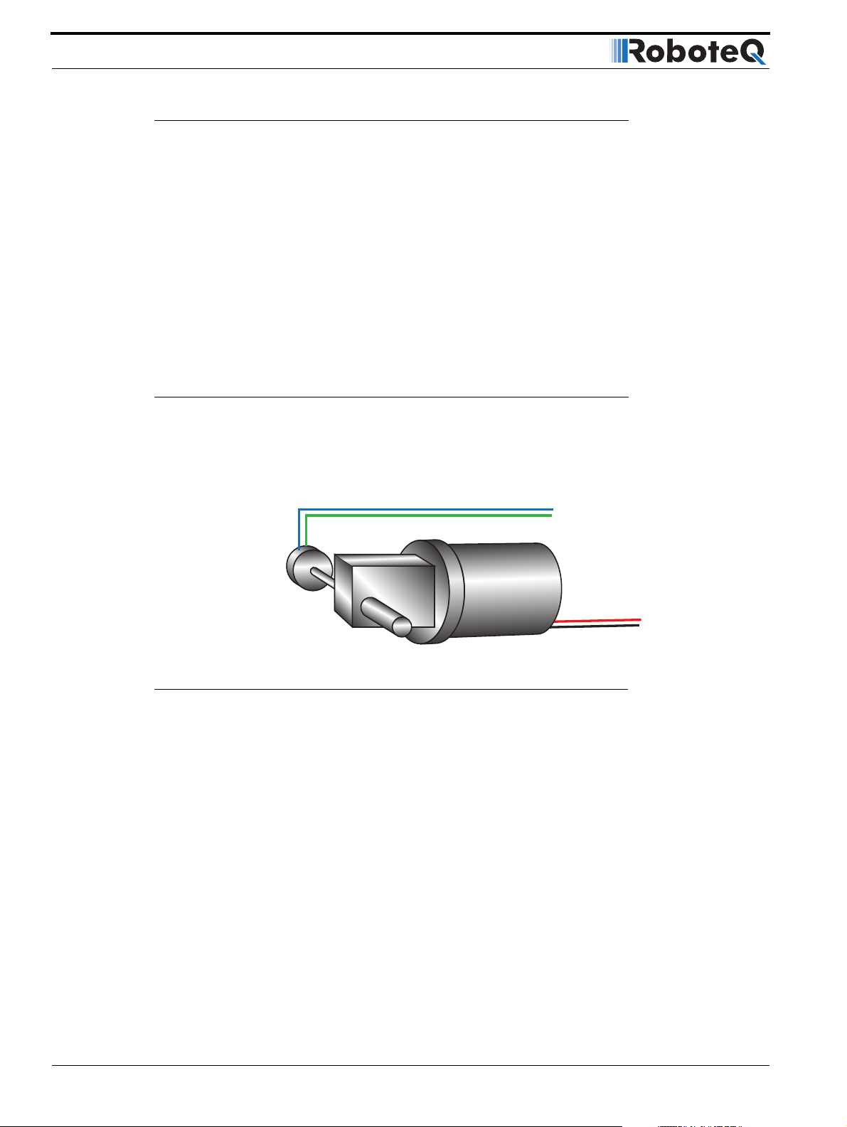
Closed Loop Position Mode
Position Sensor Selection
The AX2550 may be used with the following kind of sensors:
• Potentiometers
• Hall effect angular sensors
• Optical Encoders (with Encoder Module)
The first two are used to generate an analog voltage ranging from 0V to 5V depending on
their position. They will report an absolute position information at all times.
Optical encoders report incremental changes from a reference which is their initial position
when the controller is powered up or reset. Using Optical Encoders in this mode is possible but requires special handling that is described in Figure , “Using the Encoder to Track
Pos i tion,” on page 81.
Sensor Mounting
Proper mounting of the sensor is critical for an effective and accurate position mode operation. Figure 54 shows a typical motor, gear box, and sensor assembly.
Position Sensor
Gear box
FIGURE 54. Typical motor/potentiometer assembly in Position Mode
The sensor is composed of two parts:
• a body which must be physically attached to a non-moving part of the motor assem-
bly or the robot chassis, and
• an axle which must be physically connected to the rotating part of the motor you
wish to position.
A gear box is necessary to greatly increase the torque of the assembly. It is also necessary
to slow down the motion so that the controller has the time to perform the position control
algorithm. If the gearing ratio is too high, however, the positioning mode will be very sluggish.
Position Feedback
A good ratio should be such that the output shaft rotates at 1 to 10 rotations per second
(60 to 600 RPM) when the motor is at full speed.
86 AX2550 Motor Controller User’s Manual Version 1.9b. June 1, 2007
Page 87

Feedback Potentiometer wiring
The mechanical coupling between the motor and the sensor must be as tight as possible.
If the gear box is loose, the positioning will not be accurate and will be unstable, potentially
causing the motor to oscillate.
Some sensor, such as potentiometers, have a limited rotation range of typically 270
degrees (3/4 of a turn), which will in turn limit the mechanical motion of the motor/potentiometer assembly. Consider using a multi-turn potentiometer as long as it is mounted in a
manner that will allow it to turn throughout much of its range, when the mechanical
assembly travels from the minimum to maximum position.
Important Notice:
Potentiometers are mechanical devices subject to wear. Use better quality potentiometers and make sure that they are protected from the elements. Consider using a
solid state hall position sensor in the most critical applications. Optical encoders
may also be used when operated as discussed in “Using the Encoder to Measure
Speed” on page 80.
Feedback Potentiometer wiring
When using a potentiometer, it must be wired so that it creates a voltage that is proportional to its angular position: 0V at one extreme, +5V at the other. A 10K potentiometer
value is recommended for this use.
Analog Feedback is normally connected to the Analog Inputs 1 and 2, except when the
controller is configured in Analog Mode. In Analog mode, Analog Inputs 1 and 2 are already
used to supply the command. Therefore Analog inputs 3 and 4 are used for feedback
Feedback Potentiometer wiring in RC or RS232 Mode
In RC or RS232 mode, feedback is connected to Analog Inputs 1 and 2. Connecting the
potentiometer to the controller is as simple as shown in the diagram on below.
Note that this wiring must not be used if the controller is configured in Analog mode but is
switched in RS232 after power up using the method discussed in “Entering RS232 from R/
C or Analog mode” on page 136. Instead, used the wiring for Analog mode discussed in
the next section.
AX2550 Motor Controller User’s Manual 87
Page 88
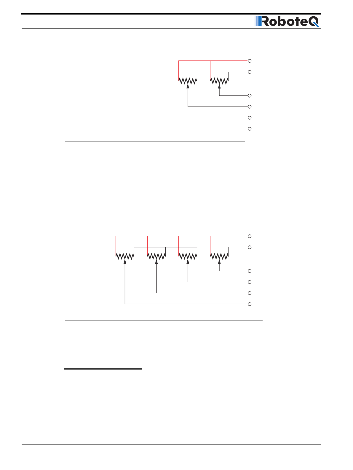
Closed Loop Position Mode
2k - 10k 2k - 10k
14 +5V
5 Ground
Feedback 1
Feedback 2
FIGURE 55. Pot wiring for RS232 or RC Command and Analog Feedback
Feedback Potentiometer wiring in Analog Mode
When the controller is configured in Analog mode, the analog inputs 1 and 2 are used for
commands while the analog inputs 3 and 4 are used for feedback. Analog inputs 3 and 4
have different characteristics than inputs 1 and 2, and so require a lower resistance potentiometer in order to guarantee accuracy
Note that the analog inputs 3 and 4 are only available on the AX2550 with PCB revision 6.1
or above. The PCB revision can be found on the sticker affixed at the bottom of the case.
Roborun will detect the new hardware revision and display Rev B on the screen.
2k 2k 2k - 10k 2k - 10k
11 Ana1
10 Ana2
12 Ana3*
8 Ana4*
14 +5V
5 Ground
FIGURE 56. Pot wiring for Analog Command and Analog Feedback
Analog inputs 3 and 4 have different characteristics than inputs 1 and 2, and so require a
lower resistance potentiometer in order to guarantee accuracy.
Important Notice
This wiring is also the one to use when the controller is in Analog mode but switched to
RS232 after reset using the method discussed in “Entering RS232 from R/C or Analog
mode” on page 136
Command 1
Command 2
Feedback 1
Feedback 2
11 Ana1
10 Ana2
12 Ana3*
8 Ana4*
88 AX2550 Motor Controller User’s Manual Version 1.9b. June 1, 2007
Page 89
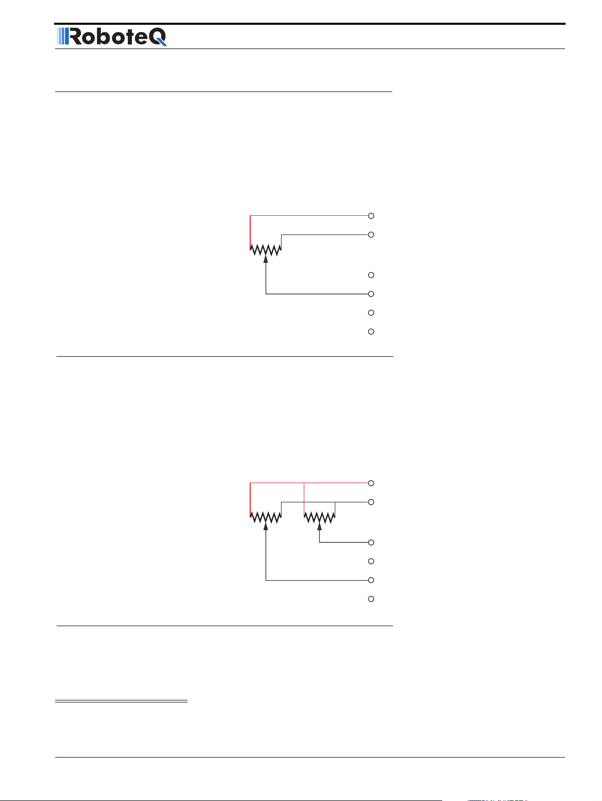
Analog Feedback on Single Channel Controllers
Analog Feedback on Single Channel Controllers
On Single Channel controllers (SC Version - not to be confused with Dual Channel controllers of which only one channel is used for position control - See “Single Channel Operation” on page 177.), the controller accepts one command and uses one input for feedback.
Feedback Wiring in RC or RS232 Mode on Single Channel Controllers
When the controller is configured for RS232 or RC command, the wiring of the feedback
must be done as shown in the figure below.
14 +5V
2k - 10k
Feedback
5 Ground
11 Ana1
10 Ana2
12 Ana3*
8 Ana4*
FIGURE 57. Pot wiring on Single Channel controllers (SCversion) and Analog Command
Feedback Wiring in Analog Mode on Single Channel Controllers
When the controller is configured in Analog mode, the analog input 1 is used for commands while the analog input 4 is used for feedback. Note that the analog inputs 3 and 4
are only available on the AX2550 with PCB revision 6.1 or above. The PCB revision can be
found on the sticker affixed at the bottom of the case. Roborun will detect the new hardware revision and display Rev B on the screen.
14 +5V
2k 2k - 10k
Command
Feedback
FIGURE 58. Pot wiring on Single Channel controllers (SC version) and Analog Command
5 Ground
11 Ana1
10 Ana2
12 Ana3*
8 Ana4*
Analog inputs 3 and 4 have different characteristics than inputs 1 and 2, and so require a
lower resistance potentiometer in order to guarantee accuracy.
Important Notice
AX2550 Motor Controller User’s Manual 89
Page 90

Closed Loop Position Mode
This wiring is also the one to use when the controller is in Analog mode but switched to
RS232 after reset using the method discussed in “Entering RS232 from R/C or Analog
mode” on page 136
Using Optical Encoders in Position Mode
The AX2550 and AX1500 may be equipped with an optional Optical Encoder Module. Optical Encoders require special handling. See Figure 7, “Installing, Connecting and Using the
Encoder Module,” on page 71 for a detailed discussion.
Sensor and Motor Polarity
The sensor polarity (i.e. which rotation end produces 0 or 5V) is related to the motor’s
polarity (i.e. which direction the motor turns when power is applied to it).
In the Position mode, the controller compares the actual position, as measured by the sensor, to the desired position. If the motor is not at that position, the controller will apply
power to the motor so that it turns towards that destination until reached.
Important Warning:
If there is a polarity mismatch, the motor will turn in the wrong direction and the
position will never be reached. The motor will turn continuously with no way of
stopping it other than cutting the power or hitting the Emergency Stop button.
Determining the right polarity is best done experimentally using the Roborun utility (see
“Using the Roborun Configuration Utility” on page 177) and following these steps:
1. Disconnect the controller’s Motor Power (thick power wires).
2. Configure the controller in Position Mode using the PC utility.
3. Loosen the sensor’s axle from the motor assembly.
4. Launch the Roborun utility and click on the Run tab. Click the “Start” button to
begin communication with the controller. The sensor values will be displayed in the
Ana1 and Ana2 boxes.
5. Move the sensor manually to the middle position until a value of “0” is measured
using Roborun utility
6. Verify that the motor sliders are in the “0” (Stop) position. Since the desired posi-
tion is 0 and the measured position is 0, the controller will not attempt to move the
motors. The Power graph on the PC must be 0.
7. Apply power to the Motor Power input (thick power wires). The motor will be
stopped.
8. With a hand ready to disconnect the Motor Power cable or ready to press the “Pro-
gram” and “Set” buttons at the same time (Emergency Stop), SLOWLY move the
sensor off the center position and observe the motor’s direction of rotation.
90 AX2550 Motor Controller User’s Manual Version 1.9b. June 1, 2007
Page 91

Encoder Error Detection and Protection
9. If the motor turns in the direction in which the sensor was moved, the polarity is
correct. The sensor axle may be tighten to the motor assembly.
10. If the motor turns in the direction away from the sensor, then the polarity is
reversed. The wire polarity on the motors should be exchanged. If using a potentiometer as sensor, the GND and +5V wires on the potentiometer may be swapped
instead. If using an Optical Encoder, ChA and ChB outputs can be swapped.
11. Move the sensor back to the center point to stop the motor. Cut the power if con-
trol is lost.
12. If the polarity was wrong, invert it and repeat steps 8 to 11.
13. Tighten the sensor.
Important Safety Warning
Never apply a command that is lower than the sensor’s minimum output value or
higher than the sensor’s maximum output value as the motor would turn forever try-
ing to reach a position it cannot. For example, if the max position of a potentiometer
is 4.5V, which is a position value of 114, a destination command of 115 cannot be
reached and the motor will not stop.
Encoder Error Detection and Protection
The AX2550 contains an Encoder detection and protection mechanism that will cause the
controller to halt if no motion is detected on either Encoder while a power level of 25% or
higher is applied to the motor. If such an error occurs, the controller will halt permanently
until its power is cycled or it is reset. An Encoder error is one of the conditions that is signaled by the LED rapidly flashing an “8” character (see “Permanent Faults” on page 106).
Adding Safety Limit Switches
The Position mode depends on the position sensor providing accurate position information.
If the potentiometer is damaged or one of its wire is cut, the motors may spin continuously
in an attempt to reach a fictitious position. In many applications, this may lead to serious
mechanical damage.
To limit the risk of such breakage, it is recommended to add limit switches that will cause
the motors to stop if unsafe positions have been reached independent of the potentiometer reading.
If the controller is equipped with and Encoder module, the simplest solution is to implement limit switches as shown in “Wiring Optional Limit Switches” on page 78. This wiring
can be used whether or not Encoders are used for feedback.
If no Encoder module is present, an alternate method is shown in Figure 59. This circuit
uses Normally Closed limit switches in series on each of the motor terminals. As the motor
reaches one of the switches, the lever is pressed, cutting the power to the motor. The
diode in parallel with the switch allows the current to flow in the reverse position so that
the motor may be restarted and moved away from that limit.
AX2550 Motor Controller User’s Manual 91
Page 92

Closed Loop Position Mode
The diode polarity depends on the particular wiring and motor orientation used in the application. If the diode is mounted backwards, the motor will not stop once the limit switch
lever is pressed. If this is the case, reverse the diode polarity.
The diodes may be eliminated, but then it will not be possible for the controller to move the
motor once either of the limit switches has been triggered.
The main benefit of this technique is its total independence on the controller’s electronics
and its ability to work in practically all circumstances. Its main limitation is that the switch
and diode must be capable of handling the current that flows through the motor. Note that
the current will flow though the diode only for the short time needed for the motor to move
away from the limit switches.
SW1 SW2
Motor
Controller
FIGURE 59. Safety limit switches interrupting power to motors
Another method uses the AX2550’s Emergency Stop input to shut down the controller if
any of the limit switches is tripped. Figure 60 shows the wiring diagram used in this case.
Each of the limit switches is a Normally Open switch. Two of these switches are typically
required for each motor. Additional switches may be added as needed for the second
motor and/or for a manual Emergency Stop. Since very low current flows through the
switches, these can be small, low cost switches.
The principal restriction of this technique is that it depends on the controller to be fully
functioning, and that once a switch is activated, the controller will remain inactive until the
switch is released. In most situations, this will require manual intervention. Another limitation is that both channels will be disabled even if only one channel caused the fault.
92 AX2550 Motor Controller User’s Manual Version 1.9b. June 1, 2007
Page 93

Using Current Limiting as Protection
Manual
Emergency
Stop Switch
FIGURE 60. Safety limit using AX2550’s Emergency Stop input
SW1
Important Warning
Limit switches must be used when operating the controller in Position Mode. This
will significantly reduce the risk of mechanical damage and/or injury in case of damage to the position sensor or sensor wiring.
Using Current Limiting as Protection
It is a good idea to set the controller’s current limit to a low value in order to avoid high cur-
rent draws and consequential damage in case the motor does not stop where expected.
Use a value that is no more than 2 times the motor’s draw under normal load conditions.
Motor
Controller
SW2
Emergency Stop InputGround
Control Loop Description
The AX2550 performs the Position mode using a full featured Proportional, Integral and Differential (PID) algorithm. This technique has a long history of usage in control systems and
works on performing adjustments to the Power Output based on the difference measured
between the desired position (set by the user) and the actual position (captured by the
position sensor).
Figure 61 shows a representation of the PID algorithm. Every 16 milliseconds, the controller measures the actual motor position and substracts it from the desired position to compute the position error.
The resulting error value is then multiplied by a user selectable Proportional Gain. The
resulting value becomes one of the components used to command the motor. The effect
of this part of the algorithm is to apply power to the motor that is proportional with the distance between the current and desired positions: when far apart, high power is applied,
with the power being gradually reduced and stopped as the motor moves to the final position. The Proportional feedback is the most important component of the PID in Position
mode.
AX2550 Motor Controller User’s Manual 93
Page 94

Closed Loop Position Mode
A higher Proportional Gain will cause the algorithm to apply a higher level of power for a
given measured error, thus making the motor move quicker. Because of inertia, however, a
faster moving motor will have more difficulty stopping when it reaches its desired position.
It will therefore overshoot and possibly oscillate around that end position.
Analog Position
Sensor
or
Optical Encoder
Desired Position
A/D
Measured Position
-
Proportional
Gain
E= Error
Integral
Gain
dE
dt
dE
dt
x
x
Σ
Output
x
FIGURE 61. PID algorithm used in Position mode
The Differential component of the algorithm computes the changes to the error from one
16 ms time period to the next. This change will be a relatively large number every time an
abrupt change occurs on the desired position value or the measured position value. The
value of that change is then multiplied by a user-selectable Differential Gain and added to
the output. The effect of this part of the algorithm is to give a boost of extra power when
starting the motor due to changes to the desired position value. The differential component
will also help dampen any overshoot and oscillation.
The Integral component of the algorithm performs a sum of the error over time. In the position mode, this component helps the controller reach and maintain the exact desired position when the error would otherwise be too small to energize the motor using the
Proportional component alone. Only a very small amount of Integral Gain is typically
required in this mode.
PID tuning in Position Mode
As discussed above, three parameters - Proportional Gain, Integral Gain and Differential
Gain - can be adjusted to tune the position control algorithm. The ultimate goal in a well
tuned PID is a motor that reaches the desired position quickly without overshoot or oscillation.
Differential
Gain
Because many mechanical parameters such as motor power, gear ratio, load and inertia are
difficult to model, tuning the PID is essentially a manual process that takes experimentation.
94 AX2550 Motor Controller User’s Manual Version 1.9b. June 1, 2007
Page 95

PID tuning in Position Mode
The Roborun PC utility makes this experimentation easy by providing one screen for changing the Proportional, Integral and Differential gains and another screen for running and
monitoring the motors.
When tuning the motor, first start with the Integral Gain at zero, increasing the Proportional
Gain until the motor overshoots and oscillates. Then add Differential gain until there is no
more overshoot. If the overshoot persists, reduce the Proportional Gain. Add a minimal
amount of Integral Gain. Further fine tune the PID by varying the gains from these positions.
To set the Proportional Gain, which is the most important parameter, use the Roborun utility to observe the three following values:
• Command Value
• Actual Position
• Applied Power
With the Integral Gain set to 0, the Applied Power should be:
Applied Power = (Command Value - Actual Position) * Proportional Gain
Experiment first with the motor electrically or mechanically disconnected and verify that
the controller is measuring the correct position and is applying the expected amount of
power to the motor depending on the command given.
Verify that when the Command Value equals the Actual Position, the Applied Power equals
to zero. Note that the Applied Power value is shown without the sign in the PC utility.
In the case where the load moved by the motor is not fixed, the PID must be tuned with
the minimum expected load and tuned again with the maximum expected load. Then try to
find values that will work in both conditions. If the disparity between minimal and maximal
possible loads is large, it may not be possible to find satisfactory tuning values.
Note that the AX2550 uses one set of Proportional, Integral and Differential Gains for both
motors, and therefore assumes that similar motors, mechanical assemblies and loads are
present at each channel.
AX2550 Motor Controller User’s Manual 95
Page 96

Closed Loop Position Mode
96 AX2550 Motor Controller User’s Manual Version 1.9b. June 1, 2007
Page 97

Mode Description
SECTION 9 Closed Loop
Speed Mode
This section discusses the AX2550 Close Loop Speed mode.
Mode Description
In this mode, an analog or digital speed sensor measures the actual motor speed and compares it to the desired speed. If the speed changes because of changes in load, the controller automatically compensates the power output. This mode is preferred in precision motor
control and autonomous robotic applications.
The AX2550 incorporates a full-featured Proportional, Integral, Differential (PID) control
algorithm for quick and stable speed control.
Selecting the Speed Mode
The speed mode is selected by changing the Motor Control parameter in the controller to
either:
• A and B Closed Loop Speed, Separate
• A and B Closed Loop Speed, Mixed
• A Closed Loop Speed, B Position
Note that in the last selection, only the first motor will operate in the Closed Loop Speed
mode.
Changing the parameter to select this mode is done using the Roborun Utility. See “Load-
ing, Changing Controller Parameters” on page 181.
For safety reasons and to prevent this mode from being accidentally selected, Closed Loop
Speed modes CANNOT be selected by configuring the controller using the built-in
switches and display.
AX2550 Motor Controller User’s Manual 97
Page 98
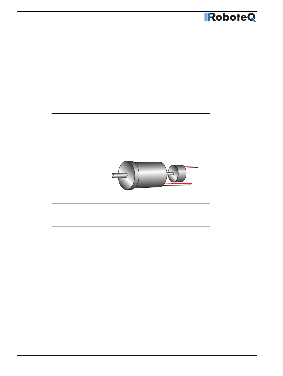
Closed Loop Speed Mode
Using Optical Encoder for Speed Feedback (AX2850 only)
Digital Optical Encoders may be used to capture accurate motor speed. This capability is
only available on controllers fitted with the optional encoder module.
Detailed information on how to install and wire optical encoders is provided at “Installing,
Connecting and Using the Encoder Module” on page 71.
If using optical encoders, omit the Analog Tachometer discussion in this section and
resume reading from “Control Loop Description” on page 100. Optical Encoders require
special handling. See “Installing, Connecting and Using the Encoder Module” on page 71
for a detailed discussion.
Tachometer or Encoder Mounting
Proper mounting of the speed sensor is critical for an effective and accurate speed mode
operation. Figure 62 shows a typical motor and tachometer or encoder assembly.
Analog Tachometer
or Optical Encoder
Speed feedbackSpeed feedback
FIGURE 62. Motor and speed sensor assembly needed for Close Loop Speed mode
Tachometer wiring
The tachometer must be wired so that it creates a voltage at the controller’s analog input
that is proportional to rotation speed: 0V at full reverse, +5V at full forward, and 0 when
stopped.
98 AX2550 Motor Controller User’s Manual Version 1.9b. June 1, 2007
Page 99
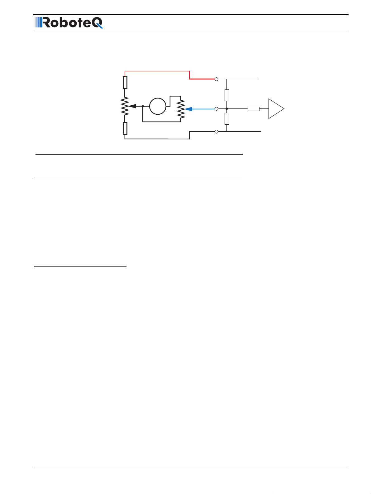
Speed Sensor and Motor Polarity
Connecting the tachometer to the controller is as simple as shown in the diagram below.
1kOhm
Zero Adjust
100 Ohm pot
1kOhm
Max Speed Adjust
10kOhm pot
Ta c h
FIGURE 63. Tachometer wiring diagram
Speed Sensor and Motor Polarity
The tachometer or encoder polarity (i.e. which rotation direction produces a positive of
negative speed information) is related to the motor’s rotation speed and the direction the
motor turns when power is applied to it.
+5V 14
Ana 1: 11
Ana 2: 10
Ana 3: 12
Ana 4: 8
Ground 5
Internal Resistors
and Converter
47kOhm
A/D
10kOhm
47kOhm
In the Closed Loop Speed mode, the controller compares the actual speed, as measured
by the tachometer, to the desired speed. If the motor is not at the desired speed and direction, the controller will apply power to the motor so that it turns faster or slower, until
reached.
Important Warning:
If there is a polarity mismatch, the motor will turn in the wrong direction and the
speed will never be reached. The motor will turn continuously at full speed with no
way of stopping it other than cutting the power or hitting the Emergency Stop buttons.
Determining the right polarity is best done experimentally using the Roborun utility (see
“Using the Roborun Configuration Utility” on page 177) and following these steps:
1. Disconnect the controller’s Motor Power.
2. Configure the controller in Open Loop Mode using the PC utility. This will cause the
motors to run in Open Loop for now.
3. Launch the Roborun utility and click on the Run tab. Click the “Start” button to
begin communication with the controller. The tachometer values will be displayed
in the appropriate Analog input value boxe(s) which will be labeled Ana 1 and Ana 2.
If encoders are used, look for the reported speed value in the Enc boxes.
4. Verify that the motor sliders are in the “0” (Stop) position.
5. If a tachometer is used, verify that the measured speed value read is 0 when the
motors are stopped. If not, trim the “0” offset potentiometer.
6. Apply power to the Motor Power wires. The motor will be stopped.
AX2550 Motor Controller User’s Manual 99
Page 100

Closed Loop Speed Mode
7. Move the cursor of the desired motor to the right so that the motor starts rotating,
and verify that a positive speed is reported. Move the cursor to the left and verify
that a negative speed is reported.
8. If the tachometer or encoder polarity is the same as the applied command, the wir-
ing is correct.
9. If the tachometer polarity is opposite of the command polarity, then either reverse
the motor’s wiring, or reverse the tachometer wires. If an encoder is used, swap its
CHA and ChB outputs
10. If a tachometer is used, proceed to calibrate the Max Closed Loop speed.
11. Set the controller parameter to the desired Closed Loop Speed mode using the
Roborun utility.
Adjust Offset and Max Speed
For proper operation, the controller must see a 0 analog speed value (2.5V voltage on the
analog input).
To adjust the 0 value when the motors are stopped, use the Roborun utility to view the
analog input value while the tachometer is not turning. Move the 0 offset potentiometer
until a stable 0 is read. This should be right around the potentiometer’s middle position.
The tachometer must also be calibrated so that it reports a +127 or -127 analog speed
value (5V or 0V on the analog input, respectively) when the motors are running at the maximum desired speed in either direction. Since most tachometers will generate more than
+/- 2.5V, a 10kOhm potentiometer must be used to scale its output.
To set the potentiometer, use the Roborun utility to run the motors at the desired maximum speed while in Open Loop mode (no speed feedback). While the tachometer is spinning, adjust the potentiometer until the analog speed value read is reaching 126.
Note: The maximum desired speed should be lower than the maximum speed that the
motors can spin at maximum power and no load. This will ensure that the controller will be
able to eventually reach the desired speed under most load conditions.
Important Warning:
It is critically important that the tachometer and its wiring be extremely robust. If the
tachometer reports an erroneous voltage or no voltage at all, the controller will consider that the motor has not reached the desired speed value and will gradually
increase the applied power to the motor to 100% with no way of stopping it until
power is cut off or the Emergency Stop is activated.
Control Loop Description
The AX2550 performs the Closed Loop Speed mode using a full featured Proportional, Integral and Differential (PID) algorithm. This technique has a long history of usage in control
systems and works on performing adjustments to the Power Output based on the differ-
100 AX2550 Motor Controller User’s Manual Version 1.9b. June 1, 2007
 Loading...