

Robot-coupe Mini MP 170 V.v., Mini MP 220 V.v., Mini MP 220 Combi, Mini MP 170 Combi User Manual
Page 1
P.O. Box 16625, Jackson, MS 39236-6625
264 South Perkins St., Ridgeland, MS 39157
e-mail: robocoup@misnet.com - website: www.robotcoupeusa.com - Phone : 1-800-824-1646
Mini MP 170 V.V.
Mini MP 220 V.V.
Mini MP 170 Combi
Mini MP 220 Combi
Page 2
WARNING
IMPORTANT WARNING
KEEP THESE INSTRUCTIONS IN A SAFE PLACE
In order to prevent accidents such as electrical shock, personal injury, fire, and in order to limit property/product damage when using your power
mixer, follow the instructions hereafter very carefully and strictly adhere to them. This manual should be kept nearby for reference and should be
read by all first time users of the power mixer.
UNPACKING
• Carefully remove the equipment from the packaging
and take out all the boxes or packets containing
attachments or specific items.
WARNING- some parts are very sharp e.g. blade.
Wear cut-resistant gloves when handling the blade.
STORAGE
• You are advised to install the wall support
provided with the machine and to store your machine
on it.
POWER SUPPLY
• Always check that your power supply corresponds
to that indicated on the serial number plate on the
motor unit and that it is properly sized.
SPECIFICATIONS
• The standard machine is operated on a standard
120 Volt, 60Hz., 15 Amp outlet.
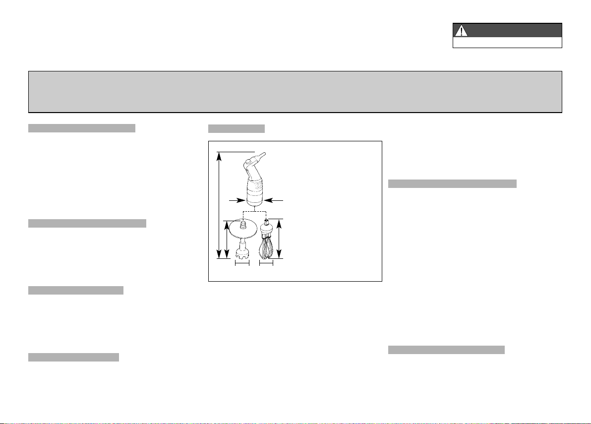
DIMENSIONS (in inches)
Mini MP 170 V.V.
A = 3
B = 18
C = 2 1/
D = 6 5/
B
D
C F
A
Mini MP 170
Combi
A = 3
B = 18 3/
C = 2 1/
E
D = 6 5/
E = 10
F = 4
Blade Attachment Capacities
• Thanks to a very powerful motor, the Mini MP
170 V.V. can process up to 4
Mini MP 220 V.V. up to 7 quarts. The quality of the
finished product is outstanding.
Whisk Attachment Capacities
• Using the whisk attachment, Mini MP 170 Combi
and Mini MP 220 Combi can process up to 20 egg
whites and puree from 2 to 16 pounds.
Mini MP 220 V.V.
A = 3
B = 20
C = 2 1/
D = 8 5/
Mini MP 220
Combi
A = 3
B = 20
C = 2 1/
D = 85/
E = 10
F = 4
1
/4,
2
8
1
/4,
2
8
3
/
8
2
8
8
2
8
3
/8 quarts and the
• For an optimum result in the mashed potatoes
quality, we recommend you to process at low speed.
• Each power mixer is supplied with a wall support
for easy storage.
SAFETY
• Safeties on motor : Thermal and overload
protection.
If there is an obstruction in the container (a spoon or
ustensil) or the machine is overused and becomes hot
the power mixer will stop. If the power mixer stops
because of a thermal overload (power mixer is too
hot), wait for a period of up to 30 minutes for the
power mixer to cool down before restarting.
• No volt release safety (Supply failure).
If there is a power failure or the machine is unplugged,
it will not restart by itself. See section on operating
the power mixer.
WARNING
Be careful when handling the blades. They are very
sharp ! Wear cut-resistant gloves when handling
the blades.
Page 3

We reserve the right to alter at any time without notice the technical specifications of this appliance. None of the information contained in this document is of a contractual nature. Modifications may be made at any time.
© All rights reserved for all countries by: ROBOT-COUPE s.n.c.
Nos reservamos el derecho de modificar en todo momento y sin previo aviso las características técnicas de este aparato.
Las informaciones que figuran en este documento no son contractuales y pueden ser modificadas en todo momento.
© Todos los derechos reservados para todos los países por : ROBOT-COUPE s.n.c.
Nous nous réservons le droit de modifier à tous moments et sans préavis les caractéristiques techniques de cet appareil.
Les informations figurant dans ce document ne sont pas contractuelles et peuvent être modifiées à tout moment.
© Tous droits réservés pour tous pays par : Robot-Coupe s.n.c.
OPERATING INSTRUCTIONS
ENGLISH
MANUAL DE INSTRUCCIÓN
ESPAÑOL
NOTICE D’INSTRUCTION
FRANÇAIS
1
Page 4

CONTENTS
ENGLISH
WARRANTY
IMPORTANT WARNING
• Unpacking
• Storage
• Power supply
• Specifications
• Dimensions
• Safety
• Warning
INTRODUCTION
SWITCHING ON THE APPLIANCE
• Advice on electrical connections
OPERATING THE MINI POWER MIXER
• Operation
• Variable-speed operation
WORKING POSITION
ASSEMBLY / DISASSEMBLY
SPLASH GUARD ASSEMBLY
CLEANING
• Motor housing
• Shaft and bell
• Blade and emulsifying disc
• Whisk
• Aluminum
• Plastic
MAINTENANCE
• Blade
• Whisk
• Shaft seal
TROUBLE SHOOTING
SERVICE
TECHNICAL DATA
• Parts diagram
• Electrical diagram
(Page 27)
3
Page 5

ROBOT-COUPE U.S.A., INC. LIMITED WARRANTY
YOUR NEW ROBOT COUPE PRODUCT
IS WARRANTED TO THE ORIGINAL
PURCHASER FOR A PERIOD OF ONE
YEAR FROM THE DATE OF PURCHASE.
This LIMITED WARRANTY is against
defects in the material and/or
workmanship, and includes labor for
replacement of defective parts,
provided repairs are performed by an
authorized service agency (see
attached list).
The Customer must inform the Service
Agency of the possibility of warranty
coverage and provide a copy of the
dated sales or delivery receipt BEFORE
WARRANTY REPAIRS ARE BEGUN.
Replacement parts and accessories are
warranted for ninety (90) days from the
date of purchase when purchased
separately and will be verified by dated
sales receipt OR packing slip which lists
that item.
All parts or accessories replaced under
warranty must be returned to the
Service Agency.
THE FOLLOWING ARE NOT
COVERED BY THE ROBOT COUPE
U.S.A. INC LIMITED WARRANTY:
1 - Damage caused by abuse, misuse,
dropping, or other similar damage caused by
or resulting from failure to follow assembly,
operating, cleaning, user maintenance or storage instructions.
2 - Labor to sharpen and/or replacements for
blades that have become blunt, chipped or worn
after a normal or excessive period of use.
3 - Materials or labor to replace or repair scrat-
ched, stained, chipped, pitted, dented or discolored surfaces, blades, knives, attachments or
accessories.
4 - Any alteration, addition, or repair that has
not been carried out by the company or an
approved service agency.
5 - Transportation of the appliance to or from
an approved service agency.
6 - Labor charges to install or test new
attachments or accessories (i.e., bowls, plates,
blades, attachments), which have been replaced
for any reason.
7 - The cost of changing direction-of-rotation of
three-phase electric motors (Installer is
responsible).
8 - SHIPPING DAMAGES. Visible and/or
hidden damage is the responsibility of the freight
carrier. The consignee must inform the carrier
and consignor immediately, or upon discovery in
the case of hidden defects.
KEEP ALL ORIGINAL CONTAINERS AND PACKING MATERIALS FOR CARRIER INSPECTION.
Neither ROBOT COUPE U.S.A., INC. nor its
affiliated companies or any of its distributors,
directors, agents, employees, or insurers will be
liable for indirect damage, losses, or expenses
linked to the appliance or the inability to use it.
The ROBOT COUPE U.S.A., INC. warranty
is given expressly and in lieu of all other
warranties, expressed or implied, for merchantability and for fitness toward a particular
purpose and constitutes the only warranty
made by ROBOT COUPE U.S.A., INC.
4
Page 6
IMPORTANT WARNING
WARNING
KEEP THESE INSTRUCTIONS IN A SAFE PLACE
In order to prevent accidents such as electrical shock, personal injury, fire, and in order to limit property/product damage when using your power
mixer, follow the instructions hereafter very carefully and strictly adhere to them. This manual should be kept nearby for reference and should be
read by all first time users of the power mixer.
UNPACKING
DIMENSIONS (in inches)
• For an optimum result in the mashed potatoes
quality, we recommend you to process at low speed.
• Carefully remove the equipment from the packaging
and take out all the boxes or packets containing
attachments or specific items.
WARNING- some parts are very sharp e.g. blade.
Wear cut-resistant gloves when handling the blade.
STORAGE
• You are advised to install the wall support
provided with the machine and to store your machine
on it.
3
/
8
2
8
8
2
8
Mini MP 220 V.V.
A = 3
B = 20
C = 2 1/
D = 8 5/
Mini MP 220
Combi
A = 3
B = 20
C = 2 1/
D = 85/
E = 10
F = 4
Mini MP 170 V.V.
A = 3
B = 18
C = 2 1/
D = 6 5/
B
D
C F
A
Mini MP 170
Combi
A = 3
B = 18 3/
C = 2 1/
E
D = 6 5/
E = 10
F = 4
• Each power mixer is supplied with a wall support
for easy storage.
1
/4,
2
8
• Safeties on motor : Thermal and overload
protection.
If there is an obstruction in the container (a spoon or
1
/4,
ustensil) or the machine is overused and becomes hot
2
8
the power mixer will stop. If the power mixer stops
because of a thermal overload (power mixer is too
hot), wait for a period of up to 30 minutes for the
power mixer to cool down before restarting.
POWER SUPPLY
• Always check that your power supply corresponds
to that indicated on the serial number plate on the
motor unit and that it is properly sized.
SPECIFICATIONS
• The standard machine is operated on a standard
120 Volt, 60Hz., 15 Amp outlet.
Blade Attachment Capacities
• Thanks to a very powerful motor, the Mini MP
170 V.V. can process up to 4
3
/8 quarts and the
Mini MP 220 V.V. up to 7 quarts. The quality of the
finished product is outstanding.
Whisk Attachment Capacities
• Using the whisk attachment, Mini MP 170 Combi
and Mini MP 220 Combi can process up to 20 egg
whites and puree from 2 to 16 pounds.
• No volt release safety (Supply failure).
If there is a power failure or the machine is unplugged,
it will not restart by itself. See section on operating
the power mixer.
WARNING
Be careful when handling the blades. They are very
sharp ! Wear cut-resistant gloves when handling
the blades.
ENGLISH
SAFETY
5
Page 7
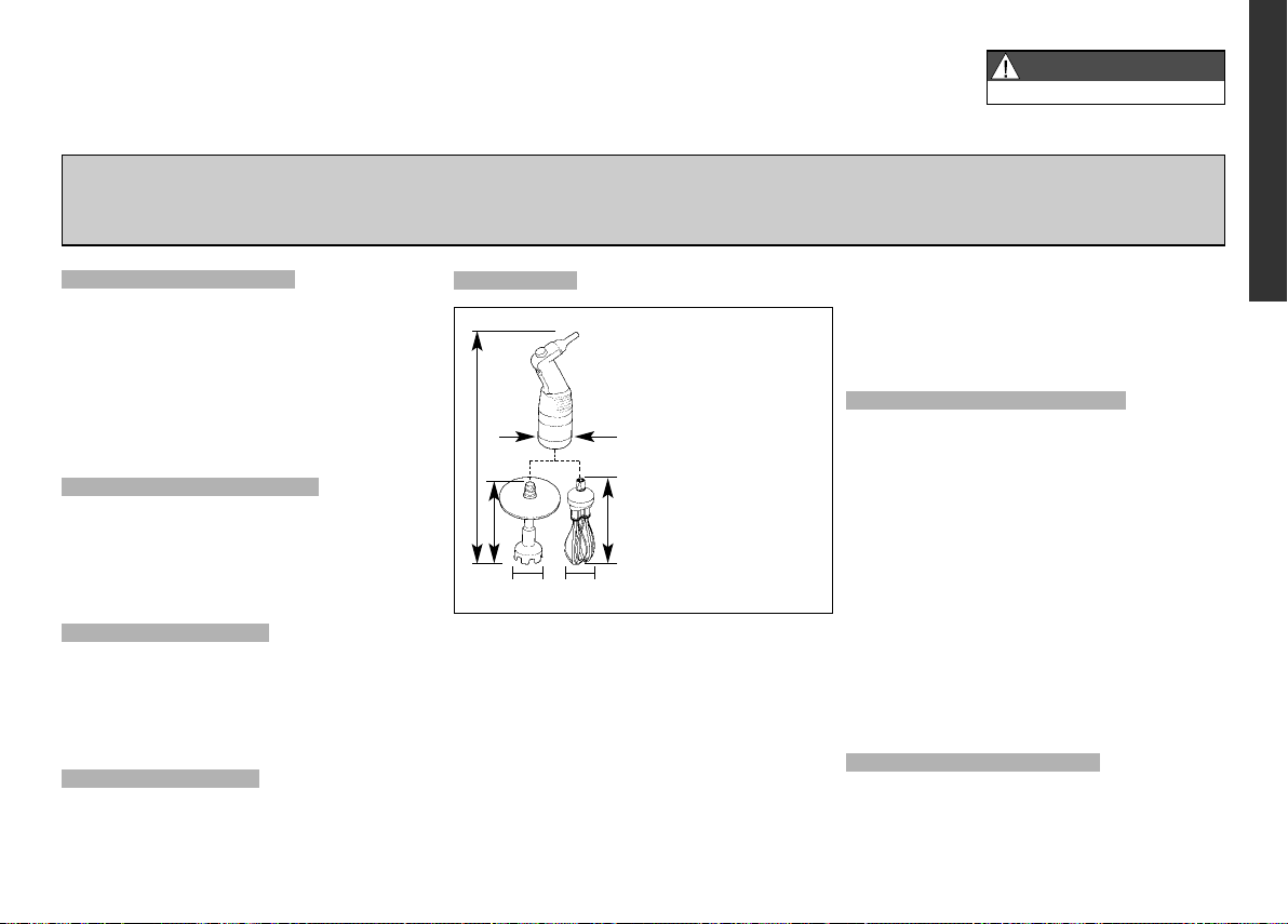
INTRODUCTION
The new Mini MP 170 V.V., Mini MP 220 V.V., Mini
MP 170 Combi and Mini MP 220 Combi models are
the latest additions to Robot-Coupe’s range of power
mixer. They have been specially designed for processing smaller quantities. They are fitted with a foot,
blades and an emulsifying disc which can be entirely
dismantled, and their shaft measure 6
5
/8 inches long respectively.
8
Models
Mini MP 170 V.V.
Mini MP 220 V.V.
Mini MP 170 Combi
Mini MP 220 Combi
Speed
variation
•
•
•
•
These power mixer are tools which are totally adapted to the needs of professionals. They will enable
you to make soups, vegetables purées and cereal
preparations with little effort.
The whisk attachment is ideal for making pancake
batter, mayonnaise, beaten egg whites, chocolate
mousse, butter sauces, whipped cream or smooth
fromage frais.
The whisk is composed with a metallic gear box
even more resistant when processing pan cakes or
mashed potatoes.
The variable-speed function will enable you to
adjust the speed to suit each preparation and to start
the processing at a lower speed in order to reduce
splashing.
Each power mixer is supplied with a wall support
for easy storage.
6
5
/8 inches and
Mixer
attachment
170 mm
220 mm
170 mm 185 mm
220 mm 185 mm
Whisk
attachment
The simple design of these appliances allows the
assembly and disassembly of the moving parts, to
ease maintenance and cleaning.
These instructions contain important information that
will enable you to extract the greatest return on your
investment.
We therefore strongly advise you to read these
instructions carefully before using the appliance.
SWITCHING ON
THE APPLIANCE
• ADVICE ON ELECTRICAL CONNECTIONS
The appliance should be plugged into a grounded
outlet.
Make sure that the voltage of your power supply
matches that shown on the identification plate of
your appliance.
OPERATING THE
MINI POWER MIXER
• OPERATION
The power mixer is equipped with electrical current
and temperature overload protection. If the power
mixer stops unexpectedly you may try to restart it
by following steps 3-5 below. If the power mixer
does not restart, allow it to cool for a period of up to
30 minutes and the temperature overload will
automatically reset. You should then be able to
restart following steps 3-5 below.
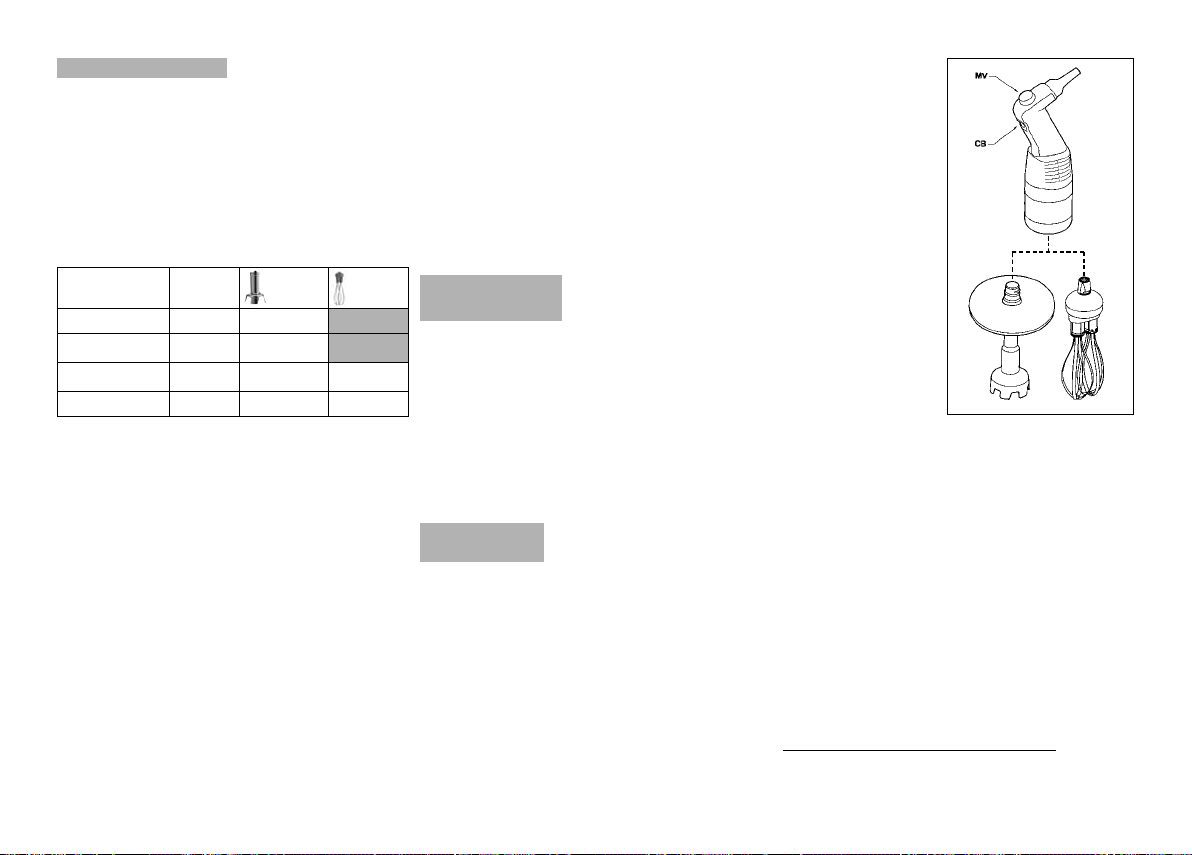
1. Plug your appliance into the
power outlet, making
sure you do not press
the button (CB).
2. Insert the foot into
the preparation.
3. Press the control
button (CB), and the
power mixer will start
up.
4. To stop the power
mixer, release the
control button (CB).
• VARIABLE-SPEED OPERATION
Follow steps 1 to 4 above, then:
5. Change the speed of the motor by turning the
variable speed button (MV) towards the maximum
or minimum as required.
Whisk function (Mini MP 170 Combi, Mini MP 220
Combi): speed between 350 and 1 560 rpm.
Mixer function (Mini MP 170 V.V., Mini MP 220 V.V.,
Mini MP 170 Combi, Mini MP 220 Combi): speed
between 2 000 and 12 500 rpm.
It is advisable to start at a low speed when using the
whisk.
With the self-regulating speed system
have selected a speed, it will remain constant, even
if the consistency of your mixture changes.
, once you
Page 8

B
A
A
B
WORKING POSITION
For a more ergonomic
approach, we recommend
that you hold the handle of
the appliance in one hand
and the container with the
other. It is a good idea to tilt
the power mixer slightly,
making sure that the bell
does not touch the bottom
of the container.
Always make sure that the bell is sufficiently immersed
to avoid splashing and that the air vents of the motor
unit do not come into contact with any liquid.
For optimum efficiency, two thirds of the shaft should
be immersed in the preparation.
Do not rest the bell against the bowl.
The splashguard should always be in place.
• WHISK FUNCTION
We recommend that you
hold the power mixer by the
handle and the bottom of
the motor unit.
You can also hold the
appliance by the handle
with one hand, leaving the
other hand free to hold the
bowl, if necessary.
While processing we recommend that you move the
whisk around in the bowl, in
order to ensure that the mixture is completely homogeneous. We strongly advise you to keep the whisk
from touching the sides of the bowl. For maximum
efficiency, at least one-fifth of the whisk length should
be immersed. We also strongly advise you to start
the processing at a low speed.
ASSEMBLY /
DISASSEMBLY
• MIXER ASSEMBLY
Attaching the shaft to the motor unit.
- Unplug the power mixer.
- Note that each end of the shaft has a threaded
plastic piece. One is longer than the other and
doesn’t have a rubber “O” ring. Insert this longer
plastic end into the motor housing , and
turn the shaft in the direction of the arrow until it is
tight.
Removing the shaft from the motor unit
- Unplug the power mixer.
- Turn the shaft counterclockwise until it is removed.
Attaching the bell to the tube
- Unplug the power mixer.
- Insert the threaded shaft into the housing of
the bell. Turn the bell in the direction of the arrow
(see drawing) until it is tight.
TURN TO ATTACH BELL
B
A
Removing the bell from the tube
- Unplug the power mixer.
- Turn the bell in the direction of the arrow (see
drawing below) to detach it from the tube.
TURN TO REMOVE BELL
ENGLISH
7
Page 9

C
E
C
D
B
A
B
A
Removing the blade
C
B
1
A
- Unplug the power mixer then, hold the blades
with the provided blade-locking tool.
- Using the blade-locking tool, unscrew the drive
coupling then remove the blade for easy cleaning.
B
LADE LOCKING
B
LADES WITH WATERTIGHT SEALS
B
ELL
REMOVAL
DIRECTION
D
RIVE COUPLING
BLADE REMOVAL
Installing the emulsifying disc
- In order to install it safely, introduce the disc into
the bell, then hold it in place using the locking tool.
- Next, turn the drive coupling with this tool until it
starts to tighten.
Removing the emulsifying disc
- The disc can be removed in exactly the same way
as the blades.
B
LADE LOCKING
S
OLID EMULSIFYING DISC
B
ELL
REMOVAL
DIRECTION
D
RIVE COUPLING
BLADE REMOVAL
8
• WHISK FUNCTION
(Mini MP 170 Combi and Mini MP 220 Combi)
Attaching the gear box to the motor unit.
- Check that the machine is not plugged in.
- Insert the threaded part into the motor unit.
- Turn the gear box in the direction of the arrow (see
figure) until it is locked into place moderately tightly.
Removing the casing
- Check that the machine is not plugged in.
- Turn the gear box in the opposite direction to that
used when attaching it.
Fitting the whisks into the gear box
- Grasp the holder in one hand.
- With the other hand, take the first whisk and insert
the shaft into the bore of the gear box
drive shaft. Make sure the drive lugs are
properly aligned with the notches.
- As you push the whisk into the gear box drive
shaft , rotate it slightly in order to slot the drive
lugs into the notches of the drive shaft ,
thereby locking the whisk into place inside the shaft.
- To check that the whisk is properly fixed inside the
shaft , gently tug the metal wires.
- Repeat this procedure with the second whisk. If you
cannot push it in properly, remove it, rotate it 90°
and start again.
Removing the whisks from the gear box
Pull the whisk in
direction to the arrow,
gripping the ejector
in one hand and the
holder in the other.
SPLASH GUARD ASSEMBLY
Cover the ring with the splash guard protection
sliding it all along the foot in the arrow
direction, the flange must be oriented down.
To remove the splash guard protection for cleaning
follow this instruction in the reverse order.
Page 10

IMPORTANT
When you use the tube with the bell for making a
preparation and then you want to use the whisk, you
need to remove the splashguard assembly from the
tube and install it on the gearbox.
The process to install the splashguard is the same for
the whisk and the tube.
CLEANING
WARNING
Always unplug the power mixer before cleaning it!
Always dilute bleach according to the instructions on
the label.
Never run the power mixer through a dishwasher!
The type and concentration of the sanitation agent
must comply with 21 CFR 178.1010 regulations.
Clean according to local health department regulations.
• MOTOR HOUSING
The power mixer must be clean through all stages
of production. Clean between each job using
a detergent or disinfectant. Dilute the detergent/
disinfectant following the instructions normally
specified on it’s packaging container. Use a cloth
lightly dampened (not dripping) with the cleaning
solution. Do not allow liquid to come into contact
with the electrical components contained within the
housing. Be careful when cleaning around vents do
not allow liquid to drip or seep into the housing.
Use a cloth lightly dampened (not dripping) with
water to remove detergent/disinfectant then dry
using a clean cloth.
After using the power mixer in a hot mixture, cool
the bottom of the tube in cold water before disassembling the bell from the shaft.
Clean immediately after use to prevent product from
sticking to surfaces.
WARNING
Never immerse motor housing and/or handle in
liquid! The housing contains the electrical components
and is not sealed against liquid. Contact with liquid
can cause damage to the blender and serious injury to
the operator.
• SHAFT AND BELL
There are two ways to proceed:
Simple cleaning procedure
Submerge the shaft and bell in water and run for a
few seconds to clean. Unplug the power cord.
Complete cleaning procedure
Unplug the power mixer and rinse the bell under a
water tap. Remove the bell from the shaft, then
remove the blade (wear cutting gloves) ! Be careful
to avoid damaging the surface of the blade shaft
and the watertight seals. Always dilute the detergent/disinfectant (see above). Thoroughly dry all
parts before reassembling.
• BLADE AND EMULSIFYING DISC
The Blade and the emulsifying disc can be removed
from the bell for thorough cleaning. Always dry
thoroughly to avoid spotting.
• WHISK
The whisks can be cleaned either by hand or in a
dishwasher.
Never immerse the gear box in water or in a
dishwasher.
Clean it with a slightly damp cloth or sponge.
• ALUMINUM
Use soft-metal-safe cleaning agents!
• PLASTIC
Be careful, many cleaning agents are corrosive and
are not safe for use on plastics !
Do not use strong alkaline detergent (having a high
concentration of soda or ammonia).
MAINTENANCE
• BLADE
Over time the blades will become worn and will
need to be replaced. The washer and seals should
also be replaced at this time. A blade service kit is
available.
ENGLISH
9
Page 11

• WHISK
The success of your preparation will depend essentially on the state of the metal wires and their amount
of wear and tear. They should therefore be replaced
from time to time in order to ensure optimum quality
of the finished product.
• SHAFT SEAL
In order to maintain a watertight seal between the
shaft and bell, inspect the seal for wear and replace
it if necessary.
TROUBLE SHOOTING
THE POWER MIXER DOES NOT START.
- Did you follow the previous operating instructions?
See section-Operating The Power Mixer.
- Pull the plug and try another outlet.
- Check outlet for current (breaker or fuse).
- Call local Robot Coupe authorized service agency.
THE POWER MIXER STOPS DURING (WHILE)
PROCESSING.
See the section on Operating the power Mixer. The
first paragraph describes the overload protection. It
may be necessary to allow the machine to cool for
up to 30 minutes before restarting.
If you cannot locate the cause of the problem
- Release the control button (CB).
- Unplug the power mixer.
10
- Are the blades free to rotate in the bell ?
- Is the drive shaft free to rotate ? To check this,
unplug the power mixer, remove the bell and test
the rotation of the end of the drive shaft manually.
Check the condition of the plug and the power cord.
THE POWER MIXER STARTS TO SMELL HOT OR
SMOKE.
Turn the power mixer off and unplug it. Call your
local authorized service agency.
WARNING
THE BLADES ARE SHARP! It is recommended that
cutting gloves be worn when handling the blades.
Handle and store the blades with safety in mind.
Never try to override or defeat the purpose of the
safety mechanisms!
Never put anything (utensils etc.) but food material
near the blades on the power mixer!
Never overload the power mixer!
Never turn the power mixer on, unless the bell is
completely immersed in the product.
Always unplug the power mixer before doing any
cleaning or maintenance!
SERVICE
See warranty first then;
Should your unit require service, check with
your distributor to see where local service is
available. If not or if you wish your unit to be
serviced at the factory, call for return instructions and
ship the unit prepaid to our factory address.
PH : 1-800-824-1646
Robot-Coupe USA, Inc
Service Department Repair
264 South Perkins Street
Ridgeland, MS 39157
For service in Canada contact the Robot-Coupe
USA factory for repair instructions.
Page 12

TECHNICAL DATA
DATOS TÉCNICOS
DONNÉES TECHNIQUES
27
Page 13

20
22
26
27
28
29
30
31
32
33
REV : bMaj : 12/2006
Mini MP 170 V.V. 34 403
19
21
12
13
14
15
23
16
24
25
17
18
®
robot coupe
10
11
01
02
03
05
07
09
08
06
04
Page 14

REV : b Maj : 12/2006
34 403
Mini MP 170 V.V.
U.S.A., Inc.
39 053 COMPLETE MMP BELL COVER ASSEMBLY ENS. CLOCHE COMPLETE MMP 5 39 057 BELL COVER RING ASSEMBLY ENS. CLOCHE-BAGUE MMP
104 416 NSF MIXER Mini MP PROTECTION PROTECTION NSF MIXER Mini MP
507 075 SEAL JOINT TORIQUE Ø 21,6 X 2,4
2
3
4
104 207 Mini MP 170 FOOT PIED Mini MP 170 EQUIPE
1
Index Pièce / Part Description Désignation
39 054 MMP BLADE ASSEMBLY ENS. COUTEAU MMP
6
104 312 DRIVING FRAME ASSEMBLY CAGE D’ENTRAINEMENT EQUIPEE 8 507 198 SEAL RING GARNITURE D’ETANCHEITE
7
39 150 DISC ASSEMBLY ENS. DISQUE EMULSIONNEUR PLEIN
39 055 RIGHT HANDLE-CAP SCREW ASSEMBLY ENS. ½ POIGNEE DROITE-CACHE VIS
9
10
39 056 CAP KNOB-CAP SCREW ASSEMBLY ENS. CAPUCHON-BOUTON-CACHE VIS
11
39 059 VARIA SWITCH EQUIP-CAP SCREW ASSEMBLY ENS. BOUTON VARIATEUR EQU-CACHE VIS
39 060 KNOB SPRING-CAP SCREW ASSEMBLY ENS. RESSORT-BOUTON-CACHE VIS
39 061 KNOB-CAP SCREW ASSEMBLY ENS. BOUTON-CACHE VIS
39 170 CIRCUIT BOARD PLATINE
12
13
14
15
39 172 ELECTRICAL WIRING FIL ELECTRIQUE
39 058 TOOL ASSEMBLY ENSEMBLE OUTIL DEMONTAGE
39 167 POWER CORD CABLE D’ALIMENTATION
39 062 L HANDLE (COVER)+SCREW+CAP ASSEMBLY ENS. ½ POIGNEE G(CAPOT)+VIS+CACHE
104 231 RACK SUPPORT MURAL MMP Combi
16
17
18
19
20
39 063 SCREW-CAP SCREW ASSEMBLY ENS. VIS 3x19-CACHE VIS
39 176 MOTOR MOTEUR
39 067 VENTILATOR CAP SCREW ASSEMBLY ENS. VENTILATEUR-CACHE VIS
39 066 VENTILATOR PIPE-CAP SCREW ASSEMBLY ENS. CONDUIT VENTILATEUR-CACHE VIS
39 174 BRUSH CHARBON
39 065 MOTOR RING-CAP SCREW ASSEMBLY ENS. BAGUE MOTEUR-CACHE VIS
39 068 FERRULE Mini MP 170 V.V.-CAP SCREW ASSEMBLY ENS. VIROLE Mini MP 170 V.V.-CACHE VIS
39 070 MOTOR FERRULE MMP-CAP SCREW ASSEMBLY ENS. VIROLE MOTEUR-CACHE VIS
39 158 MOTOR O RING-CAP SCREW ASSEMBLY ENS. JOINT MOTEUR-CACHE VIS
39 159 ALUMINIUM CASING-CAP SCREW ASSEMBLY ENS. CARTER ALU-CACHE VIS
21
22
23
24
25
26
27
402 239 ADHESIF SECURE LABEL : ATTENTION ETIQUETTE ATTENTION
28
29
402 238 ADHESIF SECURE LABEL : CAUTION ETIQUETTE CAUTION
30
31
32
39 161 M 4x16 SCREW-CAP SCREW ASSEMBLY ENS. VIS M 4x16-CACHE VIS
33
Page 15

20
22
26
27
28
29
30
31
32
33
REV : bMaj : 12/2006
Mini MP 220 V.V. 34 413
19
21
12
13
14
15
23
16
24
25
17
18
®
robot coupe
10
11
01
02
03
05
07
09
08
06
04
Page 16

REV : b Maj : 12/2006
34 413
Mini MP 220 V.V.
U.S.A., Inc.
39 053 COMPLETE MMP BELL COVER ASSEMBLY ENS. CLOCHE COMPLETE MMP 5 39 057 BELL COVER RING ASSEMBLY ENS. CLOCHE-BAGUE MMP
104 416 NSF MIXER Mini MP PROTECTION PROTECTION NSF MIXER Mini MP
507 075 SEAL JOINT TORIQUE Ø 21,6 X 2,4
2
3
4
104 211 Mini MP 220 FOOT PIED Mini MP 220 EQUIPE
1
Index Pièce / Part Description Désignation
39 054 MMP BLADE ASSEMBLY ENS. COUTEAU MMP
6
104 312 DRIVING FRAME ASSEMBLY CAGE D’ENTRAINEMENT EQUIPEE 8 507 198 SEAL RING GARNITURE D’ETANCHEITE
7
39 150 DISC ASSEMBLY ENS. DISQUE EMULSIONNEUR PLEIN
39 055 RIGHT HANDLE-CAP SCREW ASSEMBLY ENS. ½ POIGNEE DROITE-CACHE VIS
9
10
39 056 CAP KNOB-CAP SCREW ASSEMBLY ENS. CAPUCHON-BOUTON-CACHE VIS
11
39 059 VARIA SWITCH EQUIP-CAP SCREW ASSEMBLY ENS. BOUTON VARIATEUR EQU-CACHE VIS
39 060 KNOB SPRING-CAP SCREW ASSEMBLY ENS. RESSORT-BOUTON-CACHE VIS
39 061 KNOB-CAP SCREW ASSEMBLY ENS. BOUTON-CACHE VIS
39 170 CIRCUIT BOARD PLATINE
12
13
14
15
39 172 ELECTRICAL WIRING FIL ELECTRIQUE
39 058 TOOL ASSEMBLY ENSEMBLE OUTIL DEMONTAGE
39 167 POWER CORD CABLE D’ALIMENTATION
39 062 L HANDLE (COVER)+SCREW+CAP ASSEMBLY ENS. ½ POIGNEE G(CAPOT)+VIS+CACHE
104 231 RACK SUPPORT MURAL MMP Combi
16
17
18
19
20
39 063 SCREW-CAP SCREW ASSEMBLY ENS. VIS 3x19-CACHE VIS
39 176 MOTOR MOTEUR
39 067 VENTILATOR CAP SCREW ASSEMBLY ENS. VENTILATEUR-CACHE VIS
39 066 VENTILATOR PIPE-CAP SCREW ASSEMBLY ENS. CONDUIT VENTILATEUR-CACHE VIS
39 174 BRUSH CHARBON
39 065 MOTOR RING-CAP SCREW ASSEMBLY ENS. BAGUE MOTEUR-CACHE VIS
39 069 FERRULE Mini MP 220 V.V.-CAP SCREW ASSEMBLY ENS. VIROLE Mini MP 220 V.V.-CACHE VIS
39 070 MOTOR FERRULE MMP-CAP SCREW ASSEMBLY ENS. VIROLE MOTEUR-CACHE VIS
39 158 MOTOR O RING-CAP SCREW ASSEMBLY ENS. JOINT MOTEUR-CACHE VIS
39 159 ALUMINIUM CASING-CAP SCREW ASSEMBLY ENS. CARTER ALU-CACHE VIS
21
22
23
24
25
26
27
402 239 ADHESIF SECURE LABEL : ATTENTION ETIQUETTE ATTENTION
28
29
402 238 ADHESIF SECURE LABEL : CAUTION ETIQUETTE CAUTION
30
31
32
39 161 M 4x16 SCREW-CAP SCREW ASSEMBLY ENS. VIS M 4x16-CACHE VIS
33
Page 17

323334
Page 18

Page 19

Page 20

35
Page 21

37
Page 22

P.O. Box 16625, Jackson, MS 39236-6625
264 South Perkins St., Ridgeland, MS 39157
e-mail: robocoup@misnet.com
website: www.robotcoupeusa.com
Phone : 1-800-824-1646
Réf. : 404 077 - 12/2006 - Mini MP 170 V.V. • Mini MP 220 V.V. • Mini MP 170 Combi • Mini MP 220 Combi - USA
 Loading...