

Page 1
• CL 60 E
• CL 60 E V.V.
Page 2
DECLARATION OF CONFORMITY
Robot-Coupe
SNC:
Declares that the machines identified by their type above,
comply with:
• The essential requirements of the following European
directives and with the corresponding national
regulations:
- Directive «Machinery» 2006/42/EC,
- Directive «Low voltage» 2006/95/EC,
- Directive «Electromagnetic compatibility»
2004/108/EC,
- Regulation (EC) n°1935/2004 «Materials and articles
intended to come into contact with food»,
- Regulation (EU) n°10/2011 «Plastic materials and
articles intended to come into contact with food»,
- Directive «Reduction of Hazardous Substances (RoHS)
2002/95/EC,
- Directive «WEEE» 2002/96/EC,
• The requirements of the European harmonized standards
and with the standards specifying the hygiene and
safety requirements:
- EN 12100 -1 & 2 - 2004: Safety of machinery – General
principles for design,
- EN 60204-1 -2006: Safety of machinery – Electrical
equipment of machines,
- EN 12852: Food Processors and Blenders,
- EN 1678-1998: Vegetable Cutting Machines,
- EN 454: Blender-Mixers,
- EN 12853: Hand-held Blenders and Whisks (stick
blenders),
- EN 14655: Bread Slicers,
- EN 13208: Vegetable Preparation Machines,
- EN 13621: Salad Spinners,
- EN 60529-2000: Degrees of protection,
- IP 55 for the electrical controls,
- IP 34 for the machines.
Signed in Montceau en Bourgogne on 19 February 2013
Alain NODET
Industrial Director
Robot-Coupe SNC - 12 avenue du Maréchal Leclerc – BP 134 – 71305 Montceau-les-Mines Cedex - France
Page 3

SUMMARY
WARRANTY
IMPORTANT WARNING
INTRODUCTION TO YOUR NEW
VEGETABLE PREPARATION MACHINE
CL 60 E • CL 60 E V.V.
SWITCHING ON THE MACHINE
• Advice on electrical connections
• Control panel
FUNCTIONS OF HOPPERS
AND THEIR TOOLS
• Pusher feed-head
• Hole feed head
• Automatic feed head
INSTALLING THE DISCS AND TOOLS
CLEANING
MAINTENANCE
• Motor seal
• Blades and plates
• Grating discs
TECHNICAL SPECIFICATIONS
• Weight
• Dimensions
• Working height
• Noise level
• Electrical data
SAFETY
INSTALLING THE HOPPERS
• Pusher feed-head
• Hole feed head
• Automatic feed head
CHANGING THE DISCS
CHOOSING THE RIGHT DISC
VARIABLE SPEED CL 60 V.V.
STANDARDS
TECHNICAL DATA
• Exploded views
• Electrical and wiring diagrams
17
Page 4

ROBOT-COUPE S.N.C., LIMITED WARRANTY
Your new ROBOT-COUPE appliance is
warranted to the original buyer for a
period of one year from the date of sale
if you bought it from ROBOT-COUPE
If you bought your ROBOT-COUPE product
from a distributor your product is covered
by your distributor’s warranty (Please check
with your distributor terms and conditions
of the warranty).
The ROBOT-COUPE
is against defects in material and/or workmanship.
S.N.C. limited warranty
S.N.C.
THE FOLLOWING ARE NOT
COVERED BY THE ROBOT-COUPE
S.N.C. WARRANTY:
1 -
dropping, or other similar damage caused
by or resulting from failure to follow assembly,
operating, cleaning, user maintenance or storage
instructions.
Damage caused by abuse, misuse,
2 - Labour to sharpen and/ or replacements
for blades which have become blunt, chipped or
worn after a normal or excessive period of use.
3 - Materials or labour to replace or repair
scratch ed, stained, chipped, pitted, dented or
discoloured surfaces, blades, knives, attachments
or accessories.
4 - Any alteration, addition or repair that has not
been carried out by the company or an approved
service agency.
5 - Transportation of the appliance to or from an
approved service agency.
6 - Labour charges to install or test new
attachments or accessories (i.e., bowls, discs,
blades, attachments) which have been arbitrarity
replaced.
7 - The cost of changing direction-of-rotation
of three-phase electric motors (installer is
responsible).
8 - SHIPPING DAMAGES. Visible and latent
defects are the responsibility of the freight carrier.
The consignee must inform the carrier and
consignor immediately, or upon discovery in the
case of latent defects.
KEEP ALL ORIGINAL CONTAINERS AND
PACKING MATERIALS FOR CARRIER
INSPECTION.
Neither ROBOT-COUPE
companies or any of its distributors, directors,
agents, employees, or insurers will be liable for
indirect damage, losses, or expenses linked to the
appliance or the inability to use it.
The ROBOT-COUPE S.N.C. warranty is given
expressly and in lieu of all other warranties, expressed or implied, for merchantability and for fitness toward a particular
purpose and constitutes the only warranty
S.N.C. nor its affiliated
18
made by ROBOT-COUPE
S.N.C. France.
Page 5

ATTENTION
CONSERVER CES INSTRUCTIONS
IMPORTANT WARNING
WARNING: In order to limit accidents such as electric shocks or personal injury or fire, and in order to limit material damage
due to misuse of the appliance, please read these instructions carefully and follow them strictly. Reading the operating instructions
will help you get to know your appliance and enable you to use the equipment correctly. Please read these instructions in their
entirety and make sure that anyone else who may use the appliance also reads them beforehand.
UNPACKING
• Carefully remove the equipment from the packaging and take out all the boxes or packets containing
attachments or specific items.
• WARNING - some of the tools are very sharp e.g.
blades, discs, etc..
INSTALLATION
• We recommend you install your machine on a
perfectly stable solid base.
CONNECTION
• Always check that your mains supply corresponds
to that indicated on the identification plate on the
motor unit and that it can withstand the amperage.
• The machine must be earthed.
• With the three-phase version, always check that
the blade rotates in an anti-clockwise direction.
HANDLING
• Always take care when handling the blades or
discs, as they are extremely sharp.
USE
• Never try to override the locking and safety systems.
• Never insert an object into the container where the
food is being processed.
• Never push the ingredients down with your hand.
• Do not overload the appliance.
• Never switch the appliance on when it is empty.
CLEANING
• As a precaution, always unplug your appliance
before cleaning it.
• Always clean the appliance and its attachments at
the end of each cycle.
• Never immerse the motor base in water.
• For parts made from aluminum, use cleaning fluids
intended for aluminum.
• For plastic parts , do not use detergents that are
too alkaline (i.e. containing too much caustic soda
or ammonia).
• Robot-Coupe can in no way be held responsible for
the user’s failure to follow the basic rules of cleaning
and hygiene.
MAINTENANCE
• Before opening the motor housing, it is absolutely
vital to unplug the appliance.
• Check the seals and washers regularly and ensure
that the safety devices are in good working order.
• It is particularly important to maintain and check
the attachments since certain ingredients contain cor-
rosive agents, e.g. citric acid.
• Never operate the appliance if the power cord
or plug has been damaged or if the appliance fails
to work properly or has been damaged in any way.
• Do not hesitate to contact your local Maintenance
Service if something appears to be wrong.
19
Page 6

INTRODUCTION TO
YOUR NEW VEGETABLE
PREPARATION MACHINE
CL 60 E • CL 60 E V.V.
The CL 60 is perfectly geared to professional needs.
It can perform any number of tasks, which you will
gradually discover as you use it.
The CL 60 “E” version is built from stainless steel
(100% stainless steel motor base and automatic
feed head). It has been designed to operate at two
speeds, 375 and 750 rpm, in order to ally accuracy
of cut with rapidity.
It can be fitted with any one of 4 different feed heads,
in order to increase the machine’s output, make the
user’s job easier and offer the most appropriate tool
for each type of preparation. The heads are designed
to be tilted in line with the motor base, in order to
reduce space and facilitate use.
The CL 60 is supplied with a wide range of discs
and grids to satisfy even the most demanding chefs
when it comes to processing fruit and vegetables, as
they can be used for slicing, ribbon cutting, grating,
shredding, dicing,chipping and ripple-cutting.
Its numerous functions will open the door to a whole
new culinary world.
Thanks to its simple design, all components requiring
frequent handling for maintenance or cleaning can
be fitted and removed in a trice.
To make things easier for you, this manual supplies a
breakdown of all the various fitting operations.
These instructions contain important information
designed to help the user get the most out of the CL60
vegetable preparation machine.
We therefore recommend that you read them
carefully before using your machine.
20
We have also included a few examples of use to help
you get the feel of your new machine and appreciate
its many advantages.
SWITCHING ON
THE MACHINE
• ADVICE ON ELECTRICAL CONNECTIONS
Before plugging in your appliance, check that your
power supply corres ponds to that indicated on the
machine’s identi fication plate.
WARNING
THIS APPLIANCE MUST BE PLUGGED INTO AN EARTHED
SOCKET (RISK OF ELECTROCUTION).
CL 60 Three-phase
ROBOT-COUPE CL 60 models are fitted with various
types of motors : 230 / 400 V switchable / 50 Hz / 3
400 V / 50 Hz / 3
220 V / 60 Hz / 3
380 V / 60 Hz / 3
The machine is supplied with a cable to which you
simply attach the appropriate electrical plug for your
system. The cable has four wires, one earth wire,
plus three phase wires.
If you have a 4-pin plug :
1) Connect the green and yellow earth wire to the
earth pin.
2) Connect the three other wires to the remaining
pins.
If you have more than 4 pins in the plug please note
the ROBOT-COUPE does not require a neutral wire.
Switch on the empty machine, making sure that
the blade is rotating properly in an anti-clockwise
direction.
On the motor unit, a red arrow marks the blade
rotation direction. If the blade turns in a clockwise
direction, swap over two wires :
Since GREEN/YELLOW is the earth,
DO NOT DISCONNECT.
Swap either : the
the
the
CL 60 V.V. Single phase (variable speed)
This model is fitted with a 180-260V/50-60 Hz
three-phase motor.
However, the machine has a single-phased power
supply, which a frequency regular converts into
three-phase.
The machine is supplied with a power cord to which
you simply attach the appropriate electrical plug for
your system. The cable has 3 wires: one earth wire,
plus a phase conductor and a neutral wire.
The machine must be fitted with a 20-amp plug.
and the
and the
and the
• CONTROL PANEL
”Off” button
2 green button :
“On” button for the first speed (375 rpm)
“On” button for the second speed (750 rpm)
CL 60 V.V.:
Speed Variation from
100 to 1000 rpm.
Page 7
FUNCTIONS OF HOPPERS
AND THEIR TOOLS
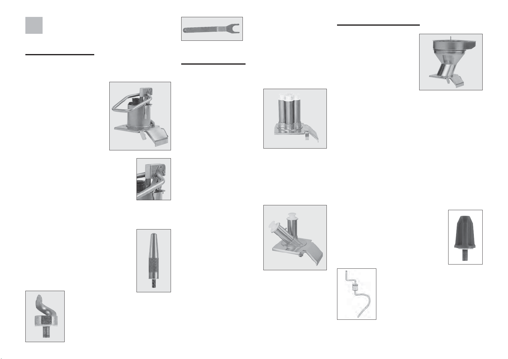
• PUSHER FEED-HEAD
This hopper allows you to prepare all types of
vegetables:
- the large feed hopper is
used to prepare bulky
vegetables such as
cabbage, celery, lettuce,
etc.,
- the tube is used to prepare
long or fragile fruit or
vegetables.
The lever-fitted feed tube can be
adjusted to 3 positions depending on
the height of the operator. To change
the position, loosen the attachment
and adjust to the desired position.
Two types of tool are designed for the lever-type
hopper:
1) The loading cone, which guides
the vegetables (except for cabbage)
towards the blades. This tool must be
screwed firmly onto the motor shaft.
2) The hollowing cutter used only to
prepare cabbage.
A special tool for unlocking
the cabbage corer.
• HOLE FEED HEADS
4 TUBES FEED-HEAD
This feed-head is equipped
with 4 straight holes: 2
straight tubes of 50 mm
diameter and 2 straight
tubes of 70 mm diameter.
This hopper is designed
for the preparation of long
vegetables like carrots, cucumbers,leeks, etc., or
of fragile fruit and vegetables such as tomatoes,
bananas, etc.
STRAIGHT AND SLOPING TUBE HOPPER
This hopper consists of
two straight tubes with
a diameter of 75 mm
diameter, a 50 mm insert
and 2 pushers of 50 mm
and 70 mm. The insert
allows you to modify the
diameter of the tubes.
This hopper performs the same functions as the
one described above with its straight tube. But it is
different in that it is equipped with a sloping tube
especially designed for slanted cutting.
No special tool is required to attach these hoppers
onto the disc.
• AUTOMATIC FEED-HEAD
This hopper is intended for
continuous cutting tasks.
It is ideal for slicing
delicate vegetables such as
mushrooms and tomatoes,
grating carrots, slicing
potatoes and cutting french
fries, to mention but a few
of its uses.
This hopper is not suitable for certain specific tasks,
such as :
- slicing long vegetables (use the hole feed-heads).
- preparing bulky vegetables which are too big to
be fed into this hopper (use the pusher feed-head).
Make sure that the agitator is in place, in order to
avoid blockages and variations in cutting quality.
It is vital that this tool be fitted each time the
automatic hopper is used.
Two types of tool are designed for the lever-type
hopper:
1) The agitator, which guides the
vegetables (except for cabbage)
towards the blades.
2) Introducing the vegetables too
quickly can result in a logjam. If this
occurs, clear the blockage using the
crank supplied for that purpose (all
other means are strictly prohibited).
The crank serves to clear the machine if it becomes
clogged up with bulky vegetables.
21
Page 8
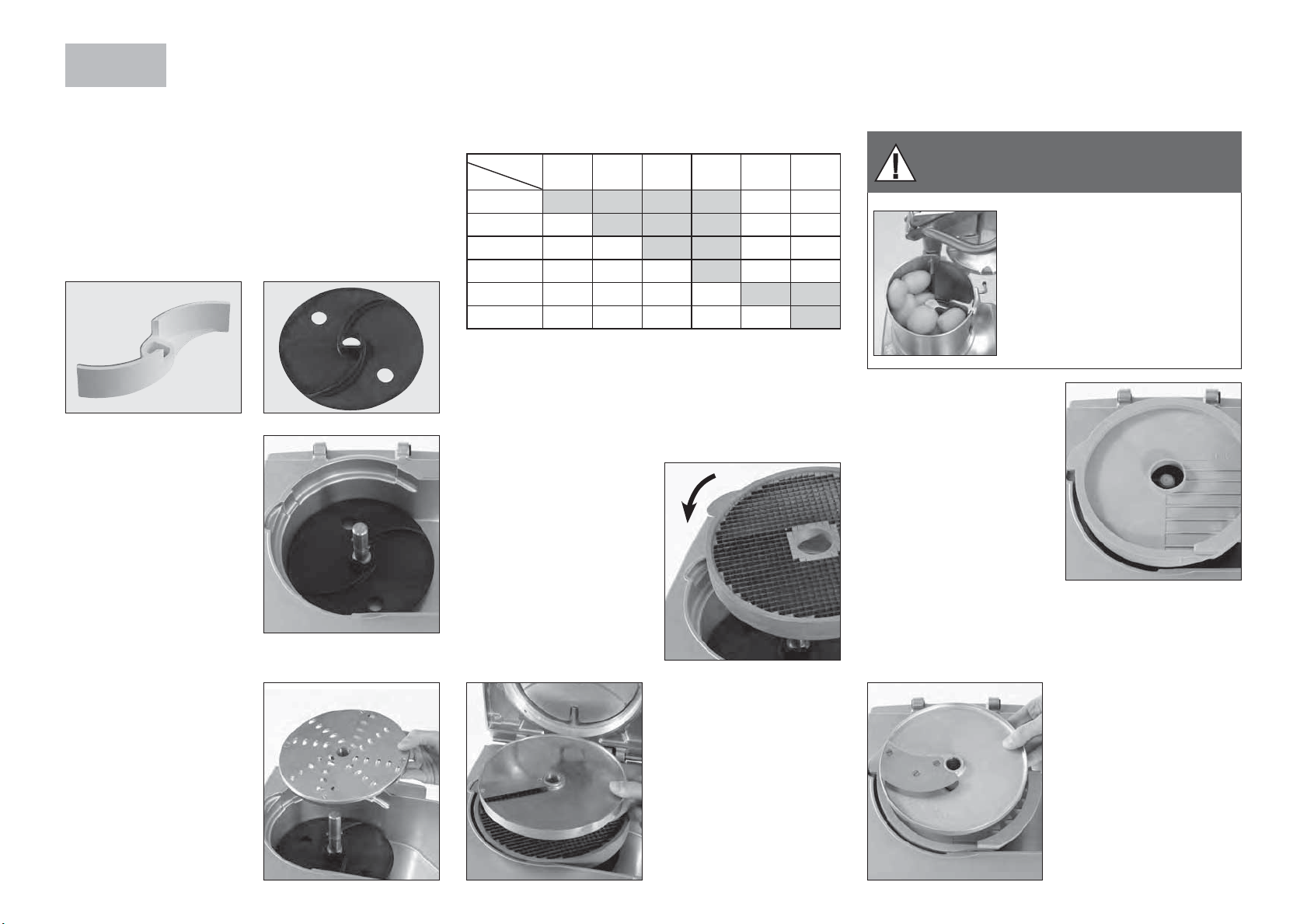
INSTALLING THE DISCS
AND TOOLS
Two ejection tools:
The CL 60 is supplied with two ejection tools. The
white ejector has been specially designed to cope
with cabbage. For all other vegetables, use the black
plastic ejector disc.
With the motor unit
facing you, slot the black
or white ejection tool
onto the motor shaft and
check that it is properly
positioned at the bottom
of the bowl.
Position your chosen disc:
b) You have chosen a dicing unit:
i.e. a grid and a special slicing disc for diced
vegetables.
Slicing discs and dicing grids can be mounted in the
following combinations:
Dicing grid
Slicer
5 mm
8 mm
10 mm
14 mm
20 mm
25 mm
You will find all the combinations marked • on our
machines and accessories price list.
The dimensions of the dicing grid should always be
equal to or greater than those of the slicing disc.
Place the dicing grid in
the bowl of the vegetable
processor.
Make sure that the spur on
the grid is fully engaged
in the locking slot of the
motor unit.
5x5 mm8x8 mm10x10 mm14x14 mm20x20 mm25x25
mm
• •••••
• • ••••
••• • ••
•••• ••
••••• •
••••••
c) If you want to use the French fries potatoes
cutting equipment:
This equipment comprises a French fries grid and a
special French fries slicing disc.
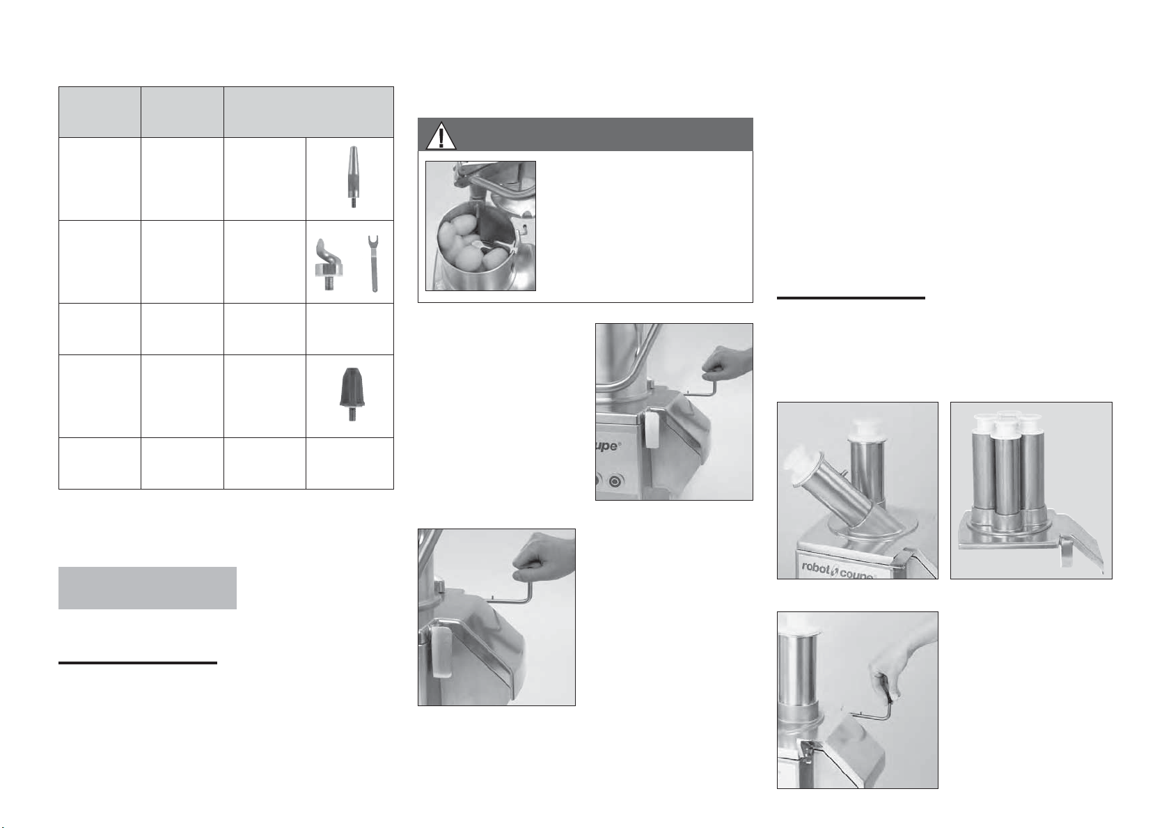
WARNING
PUSHER FEED HEAD
To get the very best results
when cutting french fries,
remember to insert the removable
divider in the hopper and
load the potatoes into the lefthand compartment (see photo
opposite).
Position the French fries
grid in the vegetable
preparation bowl.
Check that it is correctly
positioned with the French
fries plate positioned at
the outlet.
No tools (loading cone or cabbage corer) are
required when using the divider.
a) If you have opted
for a slicing, grating or
julienne disc:
Position the disc on the
motor shaft. To ensure that
it is correctly positioned,
turn it in a clockwise
direction.
22
Next, fit the corresponding
slicing disc (straightedged blade) and rotate
in a clockwise direction to
ensure that it is correctly
positioned.
Next fit the appropriate
slicing disc and rotate in
a clockwise direction to
check that it i correctly
positioned.
Page 9
The choice of disc-fixing tool will vary according
to the hopper and the type of vegetable:
Always press the vegetables down with a pusher
toimprove cutting efficiency.
- Press the pusher down to guide the food through
the machine. The exact amount of pressure
Hopper Vegetable Tool
Pusher
Pusher Cabbage
Pusher French fries
Automatic All Agitator
4-hole All No tool
All types except
for cabbage and
french fries
Loading cone
Cabbage corer
+ key
Removable
partition
+
HOW TO USE THE CYLINDRICAL HOPPER
WARNING
To get the very best results
when cutting french fries,
remember to insert the
removable divider in the
hopper and load the potatoes
into the left-hand compartment
(see photo opposite).
Position the veg prep
hopper on the motor unit.
The locking handle should
be facing you, on the
right.
required will depend on the nature of the cut,
bearing in mind that too much force reduces
cutting quality without increasing throughput.
- Cut cabbages in half and remove the core before
processing, in order to avoid unnecessary strain
and ensure an end-product of a higher quality.
- Lift the pusher and allow access to the feed tube.
• HOLE FEED HEADS
Position the 4-hole hopper, or the straight and
inclined hole hopper, on the motor unit. The locking
handle should now be facing you, on the right.
Screw the tool (unless you are using the removable
partition) firmly onto the motor shaft.
INSTALLING
THE HOPPERS
• PUSHER FEED-HEAD
USING THE FEED TUBE
Fill the feeder right up to the top with vegetables.
Apply a downwards pressure on the pusher and
maintain it until all the vegetables have been
processed.
Slide the hinge pin into
the slots provided at the
back of the motor base.
Next, lock the lid onto
the motor unit using the
locking handle.
- Fill the feeder right up to the top with vegetables.
- Lower the pusher so that it is flush with the top of
the feed opening.
Slip the hinge pin into
the locations provided at
the back of the motor
base. The locking handle
should now be facing
you, on the right.
23
Page 10

• AUTOMATIC FEED-HEAD
Proceed as specified for the pusher-feed
et
head.
Screw the agitator
onto the motor shaft.
Screw the agitator onto
the motor shaft.
Insert the crank into
the central hub of the
head. Turn it until the
part is inside the hub.
Free the disc by lifting it by its edges.
For dicing equipment, you are advised to pull out
the grid and disc assembly together. Then remove
the discharge disc using the two holes.
If the disc is stuck, turn it slightly in the anticlockwise
direction.
Slide the hinge pin
into the slots provided
at the back of the motor
base.
Then, lock the lid onto
the motor base using the
fastening hook.
24
Position the automatic
hopper on the motor
base. The fastening hook
is now facing you on
your right.
CHANGING
THE DISCS
The machine should be switched off (by pressing the
red push-button) before starting to change the disc.
With the motor unit facing you, use your right
hand to release the aluminium fastening hook
used to lock the hopper onto the motor base.
a) Feed opening fitted with a lever:
Lift the pusher and release the bowl by tilting
it to the left so that the hopper can be tittled
backwards. Then inscrew the loading cone or
the hollowing cutter. For the hollowing cutter,
use the dismantling tool provided for that
purpose.
b) With hole feed-head:
First remove the inserts and the pushers and
then lift the fastening hood in order to tilt the
hopper backwards to release the bowl.
c) Automatic feeder:
Lift the fastening hook in order to tilb the
hopper backwards to release the bowl.
When fitting dicing equipment, it is advisable to
clean the inside of the bowl thoroughly with a
damp cloth or sponge, especially the part onto
which the grid is to be fitted.
We recommend that your remove the grid and disc
together. To make the job easier, turn the ejector
disc.
Always use a properly cleaned grid. Never process
soft foodstuffs after hard ones without properly
cleaning the grid beforehand.
Use our D-Clean Kit (ref. 39881) to clean your 5x5,
8x8 and 10x10 dicing grids quickly and easily.
Then fit the discharge disc, the slicing, grating
or julienne disc, or the dicing equipment as
described in steps 1) and 2) in the previous
section on the relevant hopper.
Close the hid using the fastening hook.
Page 11

CHOOSING
THE RIGHT DISC
SLICERS
S 0,6
amands
S 0,8
cabbage
S 1 carrot /
S 2 / S 3
S 4 / S 6 courgette / beetroot / carrot /mushroom / cucumber /
S 8 / S 10
S 1 4
RIPPLE CUT SUCER
R 2
R 3
R 5
GRATER
G 1,5
G 2
G 3
G 5
JULIENNE
J 1x8
J 2x2
J 2,5x2,5
J 2x4
J 2x6
J 2x10
J 4x4
J 6x6
J 8x8
cabbage / cucumber / onion / potato / leek
lemon / carrot / mushroom / cabbage / potato / cucumber /
courgette / onion / leek / bell pepper
bell pepper /radish / lettuce / potato / leek / tomato
courgette / potato / courgette / carrot
potato / courgette / carrot
beetroot / potato / carrot / courgette
beetroot / potato / carrot / courgette
beetroot / potato / carrot / courgette
celeriac / cheese
carrot / celeriac / cheese
carrot
cabbage / cheese
carrot / celeriac / potato / courgette
carrot / celeriac / potato
carrot
carrot / beetroot / courgette / potato
carrot / beetroot / courgette / potato
carrot / beetroot / courgette / potato / celeriac
egglant / beetroot / courgette / potato
egglant / beetroot / celeriac / courgette / potato
céleriac / patato
G 7
G 9
Parmesan/chocolate
Radish
cabbage / cheese
cabbage / cheese
DICE
D 5x5
D 8x8
D 10x10
D 14x14
D 20x20
D 25x25
D 50X75
carrot /courgette / cucumber / celeriac
potato / carrot / courgette / beetroot
potato / carrot / courgette / beetroot /turnip / onion /
apple (fruit)
potato / carrot / courgette / turnip / celeriac
potato / carrot / courgette / pineapple / turnip
potato / courgette / turnip / apple (fruit) / melon /
watermelon
salad
FRENCH FRIES
F 8x8
F 10x10
F 10x16
potato
potato
potato
CLEANING
WARNING
As a precaution, always unplug your appliance
before cleaning it (risk of electrocution).
After removing the head of the vegetable
preparation machine, take off the disc, followed by
the grid and discharge plate where necessary.
Dishwashers are best avoided in order to prevent
the aluminium from becoming tarnished. Instead we
recommend that you clean the machine by hand using
washing-up liquid.
If you do put your machine in a dishwasher, we suggest that you use a detergent designed specially for
alu minium.
Never immerse the motor base in water. Clean it
with a damp cloth or sponge.
IMPORTANT
Check that your detergent is suitable for
cleaning plastic parts. Some washing agents are too
alkaline (e.g. high levels of caustic soda or
ammonia) and totally incompatible with certain types
of plastic, causing them to deteriorate rapidly.
MAINTENANCE
• MOTOR SEAL
The motor seal on the shaft should be lubricated
regularly using a food safe lubricant.
In order to keep the motor completely watertight, it is
advisable to check the motor seal regularly for wear
and tear and replace if necessary.
The motor seal can be easily replaced without
having to remove the motor, so we strongly advise
you to ensure that is in good condition.
• BLADES AND PLATES
The blades on all our discs are wearing parts
that need to be replaced from time to time, in
order to maintain consistently high cutting
quality.
• GRATING DISCS
Grating discs deteriorate over time. We recommend
you replace them from time to time, in order to
maintain consistently high cutting quality
25
Page 12

TECHNICAL
• WORKING HEIGHT
SAFETY
SPECIFICATIONS
• WEIGHT
Net Gross
Motor base
Automatic feed-head
Pusher feed-head
Hole feed-heads
Trolley 8 kg 10 kg
Disc
0,5 kg 0,6 kg
• DIMENSIONS (in mm)
43 kg 57 kg
13 kg 16 kg
7 kg 12 kg
8 kg 11 kg
We advise you to place your CL 60 on a stable
surface. There is no recommended working height
as this is a floor-standing model.
• NOISE LEVEL
The equivalent continuous sound level when the CL 60
is operating on no-load is less than 70 dB (A).
• ELECTRICAL DATA
CL 60 V.V. single-phase supply
Motor
230 V/50-60 Hz 100 to 1000 5,8
CL 60 three-phase
Motor
230/400 V/50 Hz
switchable
400 V/50 Hz
220 V/60 Hz
Speed
(rpm)
Speed
(rpm)
375
750
375 2,7
750 3,4
450 4,7
900 6,5
Intensity
(amp.)
Intensity
(amp.)
230 V=4,5
400 V=2,6
230 V=4,1
400 V=2,3
WARNING
THE DISCS ARE EXTREMELY SHARP.
HANDLE WITH CARE.
The CL 60 is fitted with magnetic safety system
which stops the motor as soon as the large hopper
or lid is opened, thus preventing any access to the
cutting tool while it is in motion.
As soon as the lid opens, the motor stops.
To restart your machine, simply relock the lid and
press the green switch.
When using the hopper equipped with a lever, the
motor is stopped as soon as the lever is removed
from the bowl. To start the machine again, you
should simply position the lever at the aligned with
the base of the bowl.
These models are fitted with a thermal safety device
which automatically stops the motor if the machine
is left on for too long or is overloaded.
26
450 2,5
380 V/60 Hz
900 3,5
- Power shown on data plate.
The hinge pin must be fitted in its position at the back
of the motor unit before the machine is switched on.
Page 13

REMINDER
STANDARDS
Never try to override the locking and safety
systems.
Never insert an object into the container
where the food is being processed.
Never push the ingredients down with your
hand.
Do not overload the appliance.
Never switch the appliance on when it is
empty.
CL 60 V.V.
VARIABLE SPEED
• CHARACTERISTICS
The CL 60 V.V. variable speed model allows for
an even greater quality of cut thanks to a range of
speeds going from 100 to 1000 rpm.
Consult the declaration of compliance on page 2.
This speed variation allows you to adapt the speed
according to the type of cut and texture of the fruit or
vegetable being processed. This guarantees optimum
accuracy and quality of cut.
The standard CL 60 V.V. variable speed model is
fitted with a stainless steel automatic feed head. It
can be equipped as an option with a pusher feed
head and a hole feed head.
27
Page 14

174
Page 15

175
Page 16

177
Page 17

178
Page 18

179
Page 19

181
Page 20

182
Page 21

183
Page 22

185
Page 23

186
Page 24

187
Page 25

188
Page 26

189
Page 27

Head Office, French,
Export and Marketing Department:
48, rue des Vignerons
94305 Vincennes Cedex- France
Tel.: 01 43 98 88 15 - Fax: 01 43 74 36 26
Email: international@robot-coupe.com
Robot Coupe Australia Pty Ltd:
Unit 3/43 Herbert St
Artarmon NSW 2064 Australia
T (02) 9478 0300
F (02) 9460 7972
Email: orders@robotcoupe.com.au
Robot-Coupe U.K. LTD:
Fleming Way, Isleworth,
Middlesex TW7 6EU
Tel.: 020 8232 1800
Fax: 020 8568 4966
Email: sales@robotcoupe.co.uk
www.robot-coupe.com
Réf. : 404 13 - 1/2013
 Loading...