

Page 1
25/07/2017
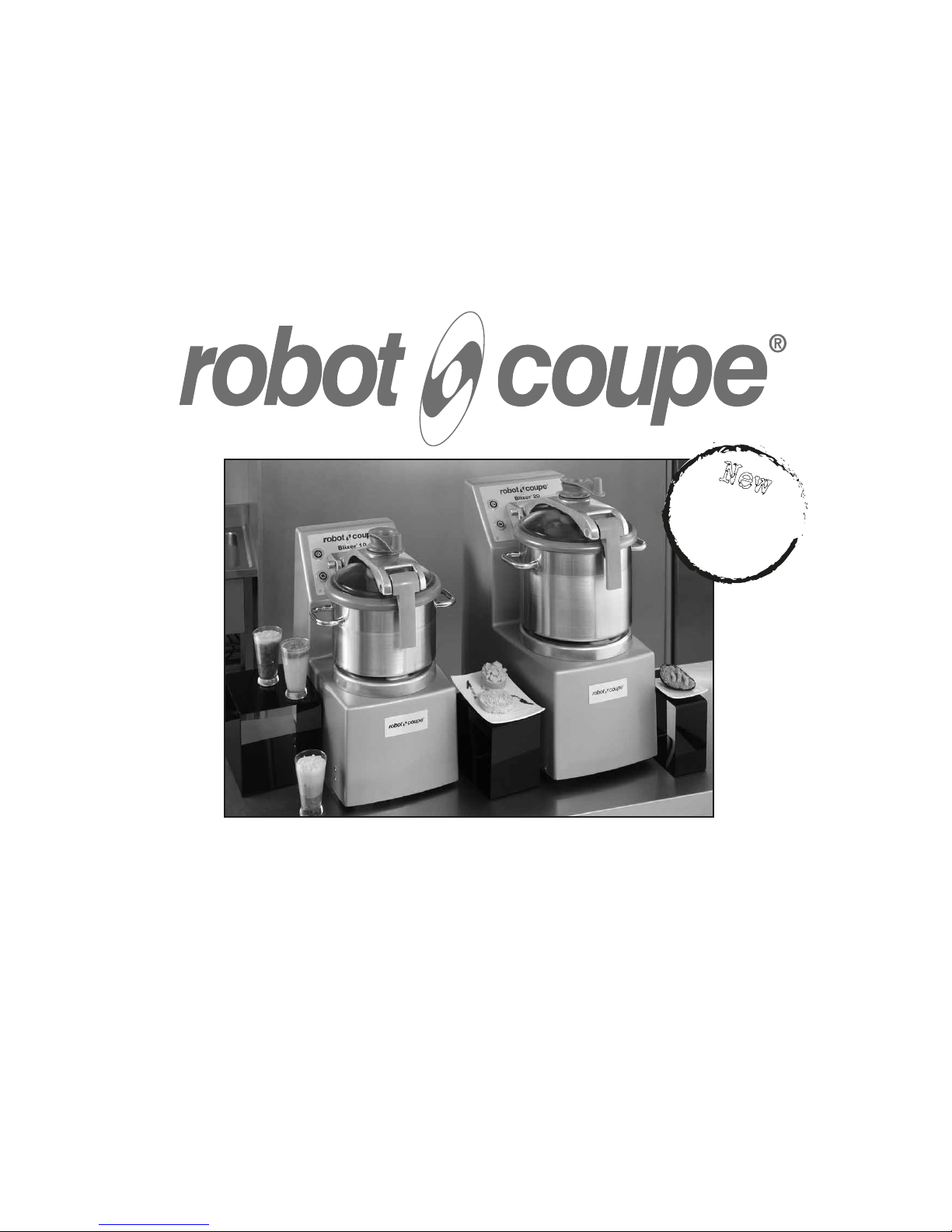
Blixer® 8 • Blixer® 10 • Blixer® 15 • Blixer® 20
Blixer® 8 V.V. • Blixer® 10 V.V. • Blixer® 15 V.V. • Blixer® 20 V.V.
New
Register
your product
on line
Page 2
www.robot-coupe.com
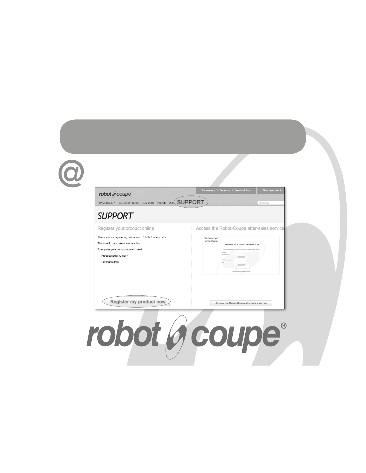
Register your product on line
Page 3

EU Declaration of Conformity
• the provisions of the following harmonized European standards
and the standards specifying the safety and hygiene requirements:
- EN ISO 12100:2010 Safety of machinery – General principles
for design,
- EN 60204-1:2006 Safety of machinery – Electrical equipment of
machines,
- EN 60529 Degrees of protection provided by enclosures (IP Code):
- IP 55 for the electric controls,
- IP 34 for the other parts of the machine,
• and according to the category of the apparatus, with the provisions
of the following harmonized European standards specifying the
safety and hygiene requirements:
- EN 454:2015
.....Planetary Mixers,
- EN 1678
...............Vegetable Cutting Machines (and Juice Extractors),
- EN 12852
............Food Processors and Blenders,
- EN 12853
............Hand-Held Blenders and Whisks (Power Mixers),
- EN 13208
............Vegetable Peelers,
- EN 13621
............Salad Dryers,
- EN 14655
............Baguette Slicers.
«R015»
Robot-Coupe SNC declares that the machines identified by
their type above, comply with:
• the essential requirements of the following European
directives and with the corresponding national regulations :
- Directive «Machinery» 2006/42/EC,
- Directive «Low Voltage» 2014/35/EU,
- Directive «Electromagnetic Compatibility» 2014/30/EU,
- Directive «Reduction of Hazardous Substances in Electrical
Equipment» (RoHS) 2011/65/EU,
- Directive «Waste Electrical and Electronic Equipment»
(WEEE) 2012/19/EU,
• regulation (EC) No 1935/2004 «Materials and Articles
intended to come into Contact with Food»,
• regulation (EU) No 10/2011 «Plastic Materials and Articles
intended to come into contact with Food» and all (EU)
regulations amending, correcting and/or rectifying it, and
entered into force prior to the date of this declaration,
namely to date the (EU) regulations No 321/2011,
1282/2011, 1183/2012, 202/2014, 865/2014,
2015/174, 2016/1416 and 2017/752.
Montceau-en-Bourgogne, on June 21, 2017
Alain NODET
Industrial Director
Robot-Coupe SNC - 12 avenue du Maréchal Leclerc – BP 134 – 71305 Montceau-en-Bourgogne Cedex - France
2
25/07/2017
Page 4

3
25/07/2017
SUMMARY
MAINTENANCE
• Dismantling the blade assembly
• Scraper arm
• Blades
• Seal
• Lid seal
DIAGNOSTIC SYSTEM
FITTING AND USING
THE BLADE ASSEMBLY
TECHNICAL SPECIFICATIONS
• Weight & Dimensions
• Working height
• Noise level
• Electrical data
SAFETY
STANDARDS
TECHNICAL DATA
• Exploded views
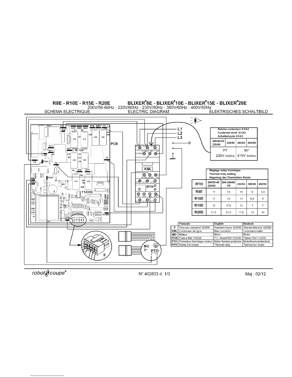
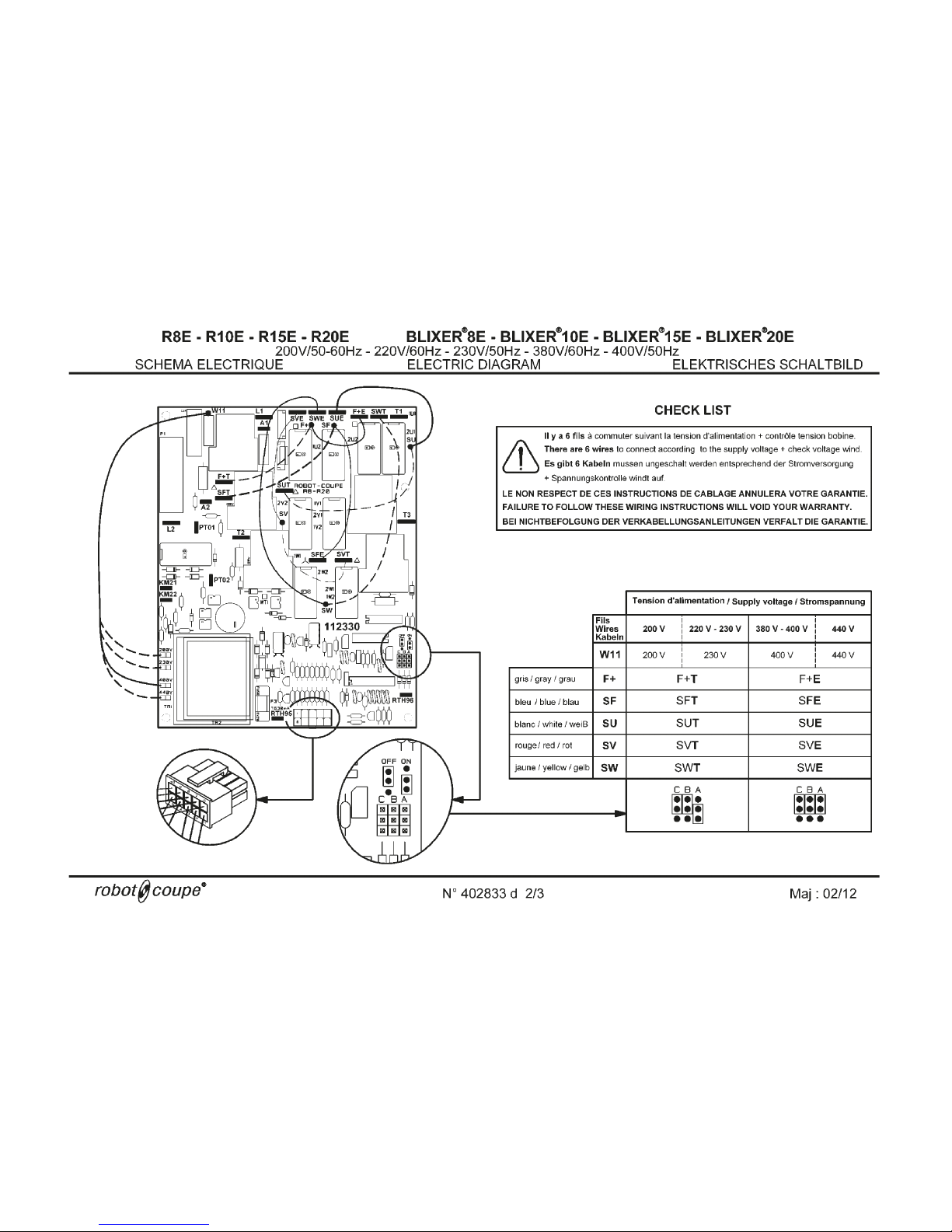
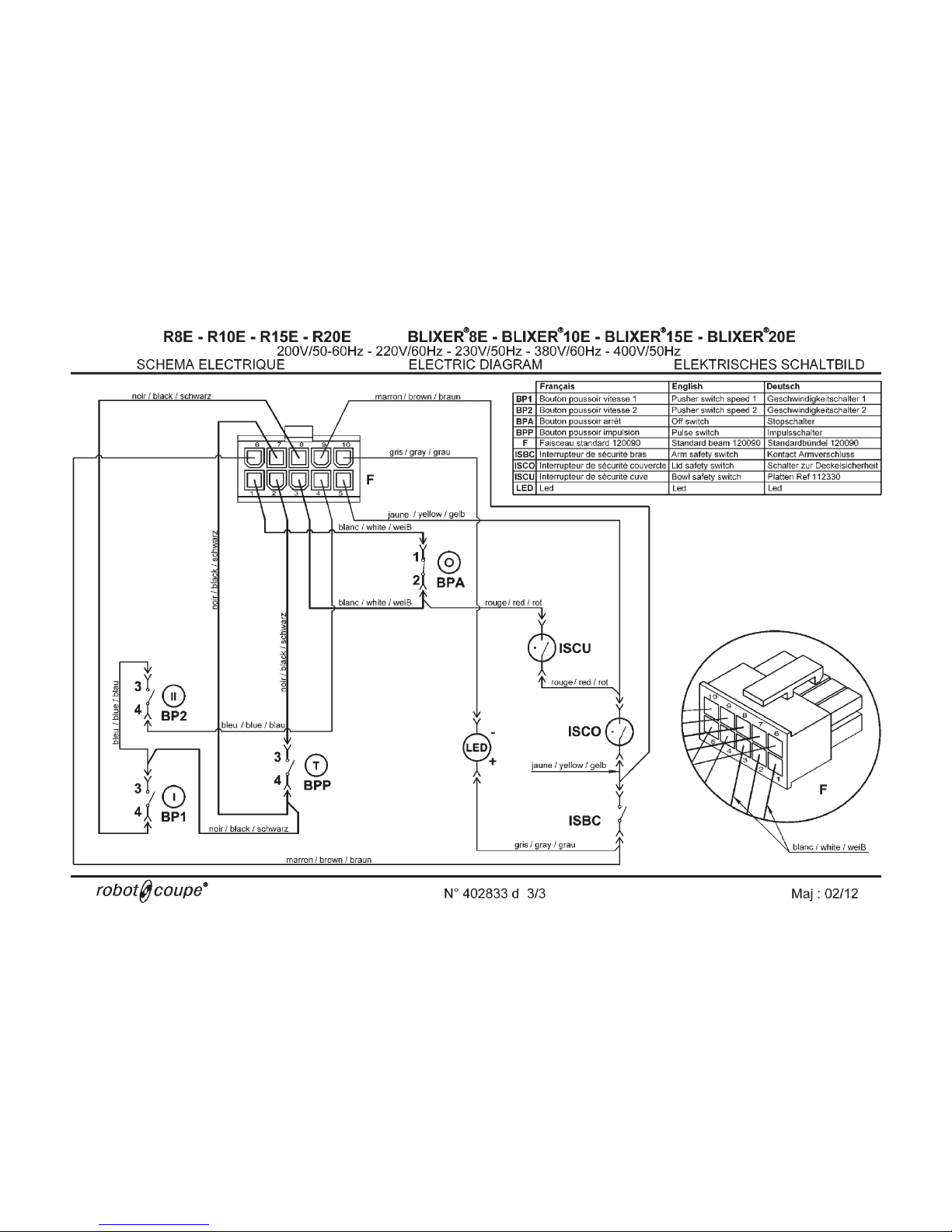
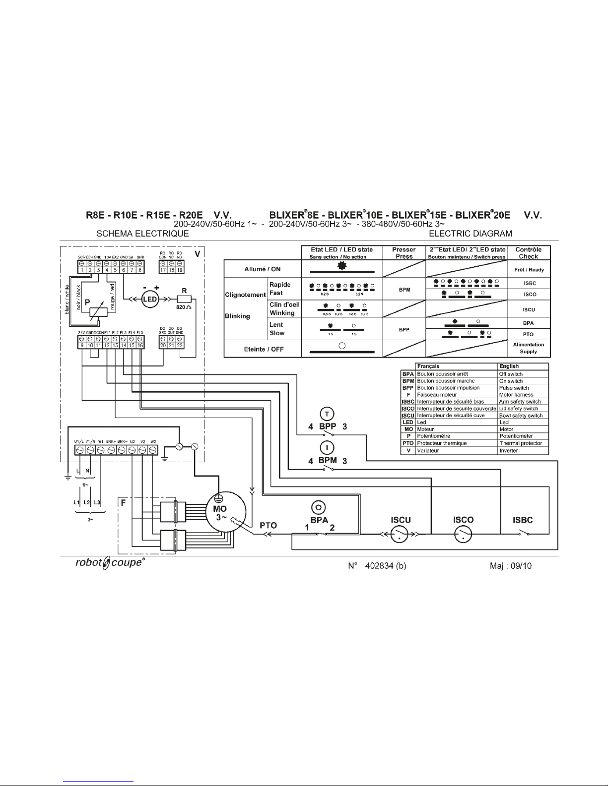
• Electrical and wiring diagrams
WARRANTY
IMPORTANT WARNING
INTRODUCTION TO YOUR NEW Blixer® 8 •
Blixer
®
10 • Blixer® 15 • Blixer® 20 •
Blixer
®
8 V.V. • Blixer® 10 V.V. •
Blixer
®
15 V.V. • Blixer® 20 V.V. CUTTER MIXER
SWITCHING ON THE MACHINE
• Advice on electrical connections
• Control panel
ASSEMBLY
• Machine
USES AND EXAMPLES
HYGIENE
CLEANING
• Motor unit
• Bowl
• Blade
• Scraper arm
Page 5

4
25/07/2017
ROBOT-cOUPE s.n.c., LIMITED WARRAnTY
Your new ROBOT-COUPE appliance is
warranted to the original buyer for a
period of one year from the date of sale if
you bought it from ROBOT-COUPE
s.n.c.
If you bought your ROBOT-COUPE product
from a distributor your product is covered
by your distributor’s warranty (Please check
with your distributor terms and conditions
of the warranty).
The ROBOT-COUPE
s.n.c.
limited warranty
is against defects in material and/or workmanship.
The ROBOT-COUPE
s.n.c.
warranty is given
expressly and in lieu of all other warranties,
expressed or implied, for merchantability
and for fitness toward a particular purpose
and constitutes the only warranty made by
ROBOT-COUPE
s.n.c.
France.
8 - SHIPPING DAMAGES. Visible and latent
defects are the responsibility of the freight carrier.
The consignee must inform the carrier and consignor immediately, or upon discovery in the case
of latent defects.
KEEP ALL ORIGINAL CONTAINERS AND PACKING MATERIALS FOR CARRIER INSPECTION.
Neither ROBOT-COUPE
s.n.c.
nor its affiliated
companies or any of its distributors, directors,
agents, employees, or insurers will be liable for
indirect damage, losses, or expenses linked to the
appliance or the inability to use it.
2 - Labour to sharpen and/ or replacements
for blades which have become blunt, chipped or
worn after a normal or excessive period of use.
3 - Materials or labour to replace or repair
scratch ed, stained, chipped, pitted, dented or
discoloured surfaces, blades, knives, attachments
or accessories.
4 - Any alteration, addition or repair that has not
been carried out by the company or an approved
service agency.
5 - Transportation of the appliance to or from an
approved service agency.
6 - Labour charges to install or test new attach-
ments or accessories (i.e., bowls, discs, blades,
attachments) which have been arbitrarity replaced.
7 - The cost of changing direction-of-rotation of
three-phase electric motors (installer is responsible).
THE FOLLOWING ARE NOT
COVERED BY THE ROBOT-COUPE
s.n.c.
WARRANTY:
1 -
Damage caused by abuse, misuse, dropping,
or other similar damage caused by or resulting
from failure to follow assembly, operating, cleaning, user maintenance or storage instructions.
Page 6

5
25/07/2017
RECOMMENDATIONS CONCERNING THE INSTALLATION OF VARIABLE-SPEED
APPLIANCES AND PERSONAL SAFETY
• You must connect the machine to a 200-240 V
/ 50 or 60 Hz single-phase alternating current
supply with an earthed socket. A higher voltage will
destroy the wobbulator.
• The earthed socket ensures operator safety.
Circuit interrupters ensuring user safety
Ground fault circuit interrupters (GFCIs) intended for
variable-speed appliances need to be selected with
great care in order to ensure operator safety. GFCIs
may be sensitive to alternating current (type AC), impulse current (type A) or all currents (type B).
Danger ! Wobbulators feature a bridge-connected
rectifier of the mains supply voltage. For this reason,
in the event of an earth contact, a continuous fault
current may fail to trip a differential circuit breaker
that is only sensitive to alternating current (type AC).
As the appliance has a single-phase supply, it is
therefore advisable to use a GFCI that is sensitive to
impulse current (type A), identified by the following
symbol: .
Caution: sthese GFCIs may go under different na-
mes, according to the manufacturer.
Appliances with wobbulators produce a fault current
on the earth wire. This current may be sufficient to
trip the differential circuit breaker unnecessarily. This
may occur if :
• Several variable-speed appliances are connected
to the same GFCI.
• The appliance produces a fault current that is above the GFCI’s actual trip threshold.
Caution: As there are manufacturing tolerances,
the actual trip threshold of a GFCI will be between
50% and 100% of its theoretical nominal threshold.
Should a problem arise, measure the fault current
and the GFCI’s actual trip threshold.
You can begin by consulting the characteristics of
your appliance in the table below:
Appliance Mains supply
Conductor
Cross-section
(mm2)
GFCI (Ph + N or 3 Ph)
Gauge (A) Threshold (mA)
Blixer
®
8 V. V.
200 - 240V
50 or 60 Hz
Single-phase
6 25
30 mA
Blixer
®
10 V.V.
Blixer
®
15 V.V.
380 - 440V
50 or 60 Hz
Three-phase
2.5 20
Blixer
®
20 V.V.
Appliance Mains supply
Conductor
Cross-section
(mm2)
GFCI (Ph + N or 3 Ph)
Gauge (A) Threshold (mA)
Blixer
®
8 V. V.
200 - 240V
50 or 60 Hz
Three-phase
2.5 20
30 mA
Blixer
®
10 V.V.
Blixer
®
15 V.V.
6 25
Blixer
®
20 V.V.
These recommendations apply to machines equipped with an induction motor and a single-phase or
three-phase wobbulator.
NB:
- The electrical circuit and the protective devices must
comply with national regulations.
- The machine must be wired in by a qualified electrician
Protecting your appliance
• Like all electronic devices, wobbulators in clude
components that are sensitive to electrostatic discharges (ESDs). Before conducting any work on
these wobbulators, technicians must therefore rid
themselves of electrostatic charges.
• The machine must be disconnected from the mains
supply before any internal connection operations
are carried out.
• Repeatedly switching on the appliance will cause
the wobbulator to overload and may result in its
destruction. After the machine has been switched
off, you must wait for 3 minutes before switching it
back on again.
50 or 60 Hz single-phase power supply
• The appliance runs on single-phase or three-phase
current as far as the variator, which turns the
current into variable frequency three-phase current
to supply the motor.
Page 7

6
25/07/2017
WARNING: In order to limit accidents such as electric shocks or personal injury, and in order to limit material damage due to misuse of the
appliance, please read these instructions carefully and follow them strictly. Reading the operating instructions will help you get to know your
appliance and enable you to use the equipment correctly. Please read these instructions in their entirety and make sure that anyone else who
may use the appliance also reads them beforehand. Our equipment is designed for professional use and must not be used by children under
any circumstances.
IMPORTANT WARNING
UNPACKING
• Carefully remove the equipment from the packa-
ging and take out all the boxes or packets containing attachments or specific items.
• WARNING - some of the tools are very sharp
e.g. blade, discs... etc.
INSTALLATION
• We recommend you install your machine on a
perfectly stable solid base.
CONNECTION
• Always check that your mains supply corresponds
to that indicated on the identification plate on the
motor unit and that it can withstand the amperage.
• The machine must be earthed.
• With the three-phase version, always check that
the blade rotates in an anti-clockwise direction.
HANDLING
• Always take care when handling the blades or
discs - they are very sharp.
ASSEMBLY PROCEDURES
• Follow the various assembly procedures carefully
(see page 8) and make sure that all the attachments
are correctly positioned.
USE
• Do not open the lid until the motor has come to a
complete stop.
• Never tamper with the locking and safety systems.
• Never put a hand object in the bowl while the
machine is operating.
• Never force the ingredients down with your
hands.
• Do not overload the machine.
CLEANING
• As a precaution, always unplung your appliance
before cleaning it.
• Always clean the appliance and its attachments at
the end of each cycle.
• Never place the motor unit in water.
• For parts made of aluminum alloys, use cleaning
fluids suitable for aluminum.
• For plastic parts , do not use detergents that are
too alkaline (i.e., containing too much caustic soda
or ammonia...)
• Robot-Coupe can in no way be held responsible
for the user’s failure to follow the basic rules of
cleaning and hygiene.
MAINTENANCE
• Before opening the motor housing, it is absolutely
vital to unplung the appliance.
• Check the seals and washers regularly and
ensure that the safety devices are in good working
order.
• It is particularly important to maintain and check
the attachments since certain ingredients contain
corrosive agents e.g. citric acid.
• Never operate the appliance if the power cord or
plug has been damaged in any way or if the appliance fails to work properly or has been damaged
in any way.
• Do not hesitate to contact your local Maintenance
Department if something appears to be wrong.
WARNING
KEEP THESE INSTRUCTIONS
IN A SAFE PLACE
Page 8

7
25/07/2017
INTRODUCTION TO YOUR
NEW Blixer
®
8 • Blixer® 10
• Blixer
®
15 • Blixer® 20 •
Blixer
®
8 V.V. • Blixer® 10 V.V.
• Blixer
®
15 V.V. • Blixer®
20 V.V. CUTTER MIXER
Robot-coupe has developed a new concept in
appliance: the Blixer
®
.
The Blixer
®
combines the features of two well-known
appliances: the cutter and the blender-mixer.
The Blixer
®
is perfectly geared to professional needs.
It can perform any number of tasks which you will
soon discover as you use it.
The Blixer
®
will make it easy to prepare mixed liquid
or semi-liquid, raw or cooked meals.
Thanks to its simple design, all components requiring
frequent handling for maintenance or cleaning are
easily fitted or removed.
To make things easier for you, this manual gives a
breakdown of all the various fitting operations.
For optimum convenience, this manual describes the
various fitting operations on a step-by-step basis.
It places special emphasis on explaining the various
actions that cause the motor to stop, as the appliance
is equipped with safety devices which prevent access
to the cutting assembly until it has come to a complete
standstill.
This manual contains important information designed
to help you get the most out of your Blixer
®
.
We therefore recommend that you read this
carefully before using your appliance.
• ADVICE ON ELECTRICAL CONNECTION
Before plugging in, check that your power supply
corresponds to that indicated on the machine rating
plate.
Blixer
®
8 • Blixer® 10 • Blixer® 15 • Blixer® 20 •
Blixer
®
8 V.V. • Blixer® 10 V.V. • Blixer® 15 V.V. •
Blixer
®
20 V.V.
ROBOT-COUPE models are fitted with various types
of motors : 220V/ 60 Hz / 3
230V/ 50 Hz / 3
380V/ 60 Hz / 3
400V/ 50 Hz / 3
The machine is supplied with a cable to which you
simply attach the appropriate electrical plug for your
system or wire to your isolator box, if wiring to an
isolator box this should be undertaken by a qualified
electrician. The cable has four wires, one earth wire,
plus three phase wires.
If you have a 4-pin plug :
1) Connect the green and yellow earth wire to the
earth pin.
2) Connect the three other wires to the remaining
pins.
If you have more than 4 pins in the plug please note
the ROBOT-COUPE does not require a neutral wire.
Switch on the empty machine, making sure that
the blade is rotating properly in an anti-clockwise
direction.
If this is not the case, contact your technical support
service.
Blixer
®
8 V.V. • Blixer® 10 V.V. Single phase
Robot-Coupe equips these models with variators
supplied with:
200V- 240V / 50 Hz or 60 Hz / 1
The machine is supplied with a cable to which you
simply attach the appropriate electrical plug for your
system or wire to your isolator box, if wiring to an
isolator box this should be undertaken by a qualified
electrician. The cable has four wires, one earth wire,
plus three phase wires.
Switch on the empty machine, making sure that
the blade is rotating properly in an anti-clockwise
direction.
If this is not the case, contact your technical support
service.
• CONTROL PANEL
Blixer® 8 • Blixer® 10 • Blixer® 15 • Blixer® 20 :
Red switch
= ”Off” button
Green switch
= “ On” button 1st speed
(1500 or 1800 rpm)
Green switch
= “ On” button 2nd speed
(3000 or 3600 rpm)
Black switch
= Pulse control
Green indicator = Safety indicators
Blixer
®
8 V.V. • Blixer® 10 V.V. • Blixer® 15 V.V. •
Blixer
®
20 V.V. :
Speed variation from 300 to 3500 rpm.
Red switch
= ”Off” button
Green switch
= “On” button
Black switch
= Pulse control
Potentiometer = Speed regulation
Green indicator = Safety indicators
WARNING
THIS APPLIANCE MUST BE PLUGGED INTO AN EARTHED
SOCKET (RISK OF ELECTROCUTION).
SWITCHING ON
THE MACHINE
Page 9
8
25/07/2017
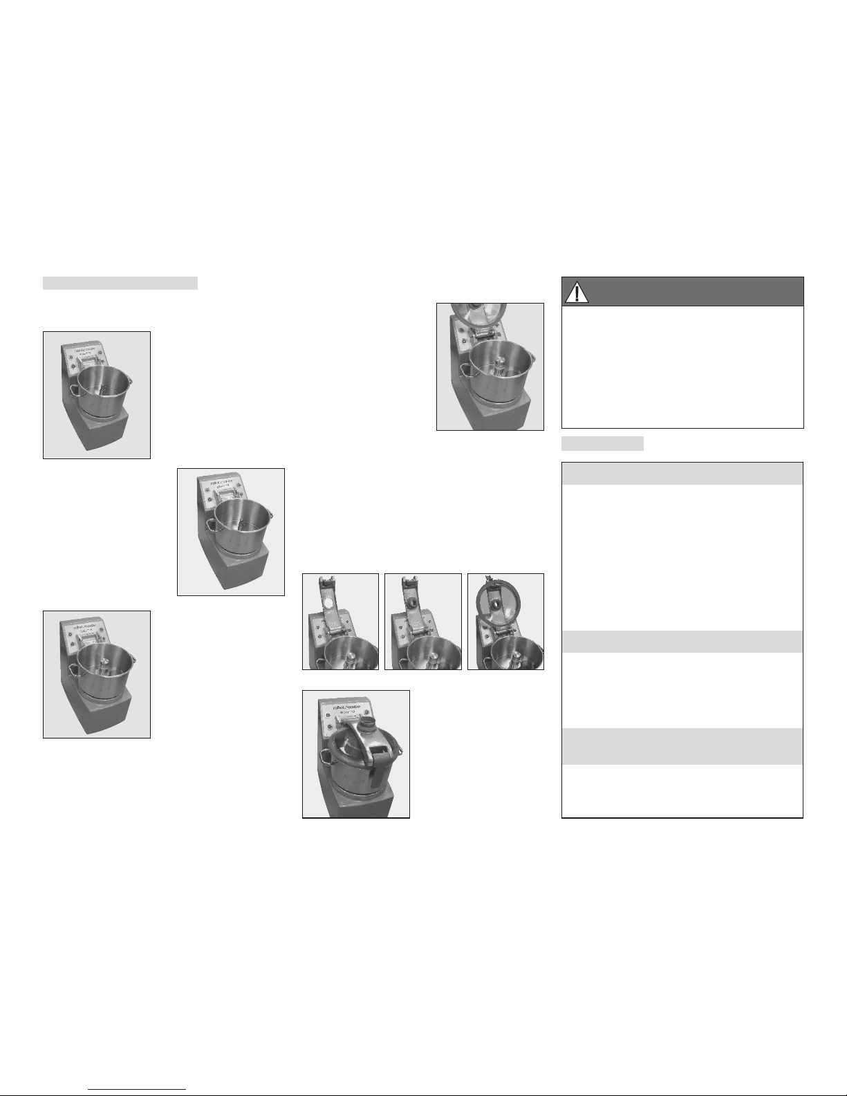
ASSEMBLY
• MACHINE
1) With the motor base
facing you, position the
bowl on the motor shaft
so that the handle on your
left is near the control
panel.
2) Pressing down on the
handles, turn the bowl
firmly in an anticlockwise
direction until it locks into
place.
3) Position the blade
mounted on the motor
shaft. Then rotate it so that
it is lowered right down to
the bottom of the bowl.
Always check that the
blade is correctly positioned at the bottom of the
bowl before adding the ingredients to be processed.
The Blixer
®
8 is supplied with a fine-serrated 2-blade
assembly.
The Blixer
®
10, 15 and 20 models are supplied with
a fine-serrated 3-blade assembly.
5) Close the lid by
securing the locking hook
to the edge of the bowl
and pushing the handle
down.
The machine is now ready
for operation.
The green indicator light
should be on.
• If the lid parts are already assembled:
4) Place the lid assembly
in the correction position.
Next, insert the metal pin
as far as it will go.
• If the lid parts have not been assembled:
4) Position the end of the lid arm in the hinge. Next,
insert the metal pin as far as it will go (drawing 1).
Push the lid guide through the lid arm hole and screw
the cone into the top of the guide (drawing 2). Clip
the lid onto the guide and turn it so that the dimples
are beneath the lid arm (drawing 3).
USES AND EXAMPLES
HOSPITAL USES
SPOON FEEDING
• Minced foods: meat, fish etc... • Vegetable purees
• Mousses: vegetables, fish etc... • Compotes of stewed fruit
SEMI-LIQUID FEEDING
This simply entails diluting spoon-feeding preparations:
• Minced meat + gravy • Puree + liquid (broth, milk. etc.)
• Soups / creamed soups • Fruit compotes + syrup or water
LIQUID FEEDING (for use via tubes)
• Soups and any preparations that can be liquidized
DELICATESSEN USES
• Butter mixtures: snail butter, salmon butter, anchovie butter…
• Sauces: green sauce, mayonnaise, remoulade, ailloli,
emulsified sauces with tomatoes, cream, parsley…
• Vegetable mousses.
• Grinding: lobster, scampi, seashells...
PHARMACEUTICAL AND CHEMICAL
LABORATORY USES
• Grinding: herbs, seeds, powders, tablets....
• Mixing: homogeneization of creams, ointments, mixed
components, varied ingredients...
WARNING
There is a green safety indicator light on the
control panel of the motor unit. If this green
light does not come on, consult the relevant
paragraph. A flashing green light means that the
conditions for the safe operation of the machine
have not all been met. Check that the bowl, lid
arm and lid are all correctly positioned. As soon
as the light stops flashing and stays on, you can
use your machine.
Page 10

9
25/07/2017
HYGIENE
• WARNING: NEVER USE PURE BLEACH.
- Correctly diluate the detergent following the
instructions given by the manufacturer which are
generally printed on the packaging.
- If necessary, well rub.
- Let the detergent operate if needed.
- Rinse meticulously.
- Well dry with an unique use cloth.
CLEANING
• MOTOR UNIT
Never immerse the motor unit in water. Clean it
with a damp cloth or sponge.
• BOWL
After removing the lid, release the bowl by pressing
the trigger built into the handle. It can then be lifted
vertically from the motor support. If the bowl contains
a liquid preparation, leave the blade assembly inside
to ensure that it remains completely watertight.
If the food has a solid consistency, remove the blade
and empty the bowl.
Replace the bowl, place the blade on the shaft and
switch on the machine in order to remove any mixture
which may have stuck to the blade.
IMPORTANT
Like the bowl and lid, the blade assembly should
also be removed for cleaning after use.
Always dry all the metal parts carefully,
especially the blades, to avoid oxidization
WARNING
As a precaution, always unplug your appliance
before cleaning it (hazard of electrocution) and
handle the blades with care (hazard of injury).
IMPORTANT
Check that your detergent is suitable for
cleaning plastic parts. Some washing agents are
too alkaline (e.g. high levels of caustic soda or
ammonia) and totally incompatible with certain
types of plastic, causing them to deteriorate
rapidly.
Drawing 1
Drawing 2
Drawing 3
The bowl can be prewashed by pouring hot water
into it and running the machine for a few minutes.
• BLADE (See page 13)
The Blixer® 8 is supplied with a fine-serrated 2-blade
assembly.
The Blixer
®
10, 15 and 20 models are supplied with
a fine-serrated 3-blade assembly.
The 100% stainless-steel blade assemblies of our
Blixer
®
can be taken apart for easy cleaning
After cleaning the blade, always dry well to prevent
rusting.
• SCRAPER ARM
To clean the scraper arm, dismantle it as follows.
Hold the scraper arm in one hand and the hub in the
other hand (drawing1). Press the two pieces one on
the other, and turn the handle of 45° anticlockwise
(drawing 2). Then it is possible to pull out the two
pieces (the scraper arm and the handle) from the lid
and clean them (drawing 3).
Page 11
10
25/07/2017
MAINTENANCE
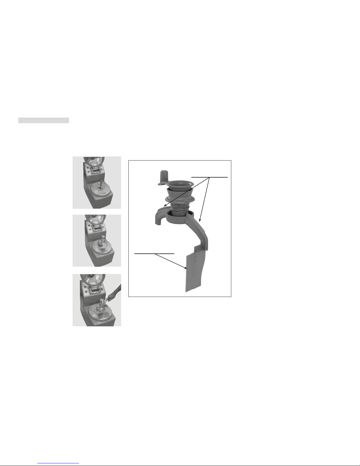
• DISMANTLING THE BLADE ASSEMBLY
1) Blixer® 8 • Blixer® 10 • Blixer® 15 •
Blixer
®
20 blade
• BLADES
The blades do not need to be sharpened.
The quality of the cut depends mainly on the
sharpness of your blades and the degree of
wear. The blades are actually wearing parts, which
should be replaced occasionally to ensure consistent
quality in the final product.
• SCRAPER ARM
The scraper arm is equipped with rubber pieces
which are wearing parts. They should be replaced
occasionally to always ensure an optimum efficiency
of the scraper arm.
These pieces are easy to dismantle and to reassemble.
• SEAL
The seal on the motorshaft should be lubricated
regularly using a food safe lubricant.
In order to keep the motor completely watertight, it is
advisable to check the gasket regularly for wear and
tear and replace if necessary.
• LID SEAL
The lid is designed to be completely watertight. In
order to ensure that it remains that way, you may
have to change the seal occasionally, depending on
how regularly you use your machine.
If you do not use your machine regularly, between
uses it is advisable to leave the lid open to preserve
all these features.
Rubber pieces to
scrape the lid.
Rubber piece to
scrape the bowl
• Disconnect the machine.
• Remove the bowl.
• Position the blade tool
on the motor shaft.
• Slide the cutter right
down the motorshaft.
• Make sure that the
lower blade is resting
on top of the blade tool.
• Loosen the locking nut
with the metal wrench.
• To replace the knife, simply do the same in
reverse.
Page 12
11
25/07/2017
1) No green light
This means that either your appliance is switched off
or there is a problem with the power supply.
Measure the voltage at the power outlet and check
that the plug is correctly wired.
(If the problem persists, see*).
DIAGNOSTIC SYSTEM
Your appliance is equipped with a light that indicates
the operational status of your machine:
- no green light: see paragraph 1.
- green flashing light: see paragraph 2.
- continuous green light: your appliance is ready to
run.
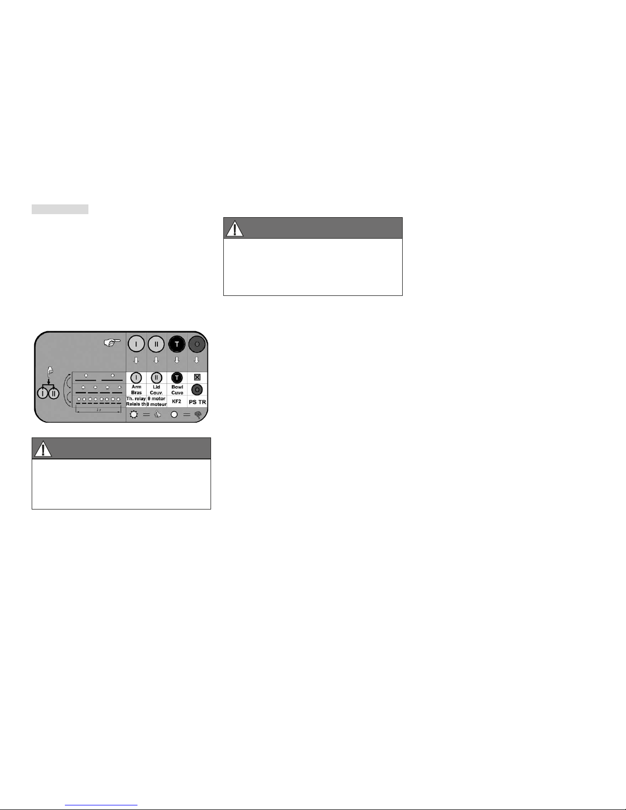
• DUAL-SPEED VERSION
2) Flashing green light
One or more of the safety devices is not responding.
These safety devices comprise 3 presence sensors, a
thermal relay and a motor overload protector.
The indicator light and the buttons offer a means of
testing the machine’s components and safety devices
before performing any sort of intervention.
There is no point continuing with the test once you
have detected a fault. Instead, rectify the problem
and start the test afresh.
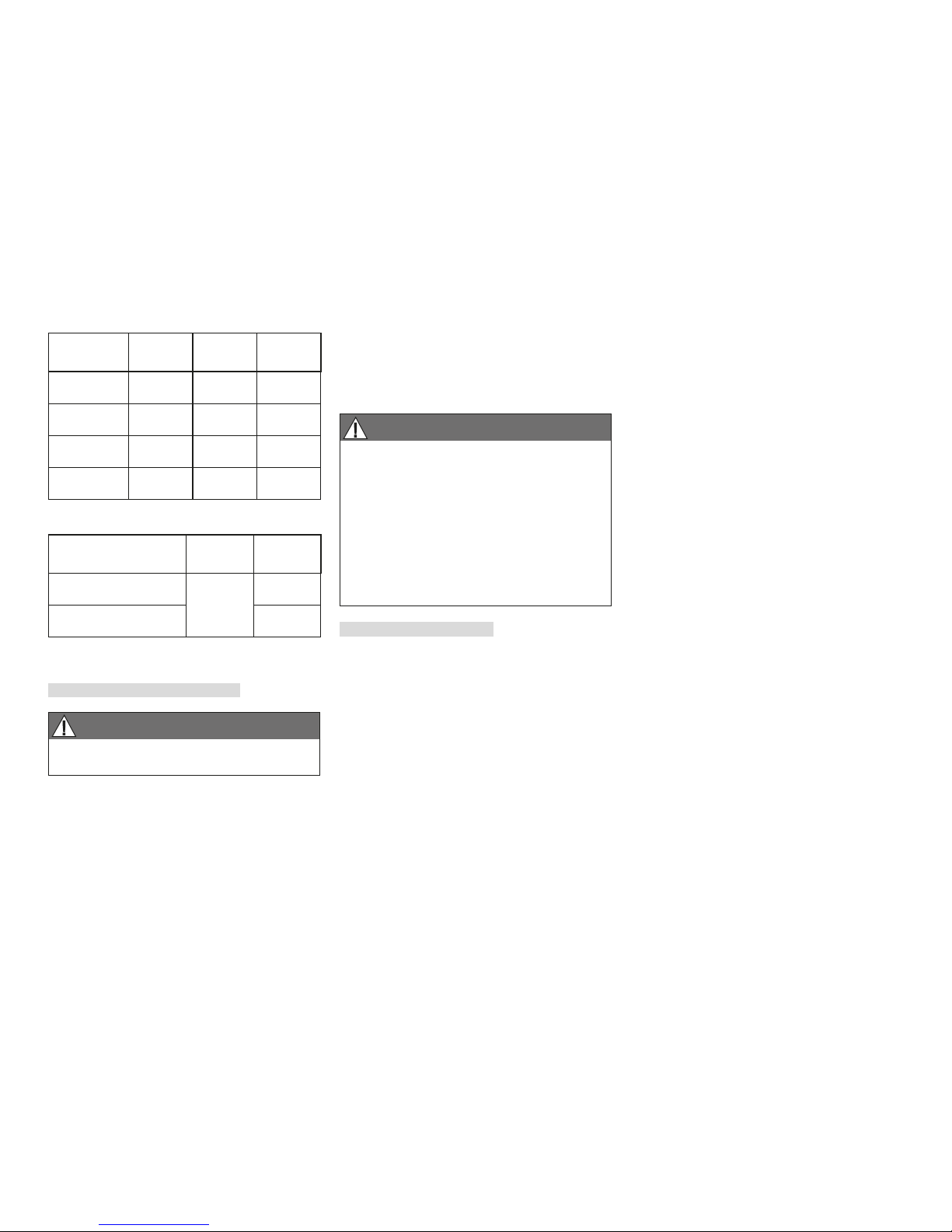
• General points:
The enclosed table is intended to help you follow the
test procedure.
Each blank square corresponds to the element being
tested.
Each of the 4 columns corresponds to one of the 4
buttons pressed one after the other by the operator.
The 3 rows correspond to the 3 successive test
levels. You can change the level by simultaneously
pressing buttons I and II. Each level is indicated by
increasingly rapid flashing of the green light: slow
for the first level, faster for the second and very fast
for the third. To return to testing level 1, the buttons
must be simultaneously pressed a further time.
When none of the buttons is being pressed, the light
flashes to indicate the testing level. When one of the
buttons is continuously pressed, it indicates the result
of the relevant test: on = OK, off = problem.
• Test sequence:
When the green light flashes, start by pressing button
I to test that it is working properly (as the buttons are
used to test the machine, it is only logical to check
that they themselves are working properly).
Press buttons II and T to test that they are working,
too.
At this level, button 0 does not test anything.
Press buttons I and II simultaneously to move up to
testing level 2, indicated by more rapid flashing of
the indicator light. At level 2, buttons I, II, T and
0 allow you to test the presence sensors of the lid,
the base and the bowl, and the contact of button 0,
respectively.
Press buttons I and II simultaneously to move up to
testing level 3, indicated by very rapid flashing of the
indicator light. At level 3, buttons I, II, T and 0 allow
you to test the thermal relay and the motor overload
protector, the mains voltage, the phase-frequency
detector, and the location of the jumpers and braking
relay, respectively.
Press buttons I and II simultaneously to return to
the normal flashing speed and therefore to testing
level 1.
• Checks
Level 1 and level 2 button 0 test:
If one of the button tests indicates a problem, check
the button’s contact block and wiring.
Level 2:
If the test reveals a problem with one of the presence
sensors, check that the removable parts of your
cutter mixer (bowl, lid and arm) are all in place.
If the problem persists, check the presence sensors
themselves and their wiring.
REMEMBER
After switching your appliance on, open
and close the lid to check that the machine is
working properly. If it is, the green light will
stop flashing and stay on.
REMEMBER
- Always switch your machine off before
carrying out any cleaning or maintenance.
- All repair and maintenance work must be
carried out by a qualified technician.
Page 13
12
25/07/2017
Level 3:
If you have not been using your machine intensively,
when it may be quite normal for the motor to overheat
and trigger the thermal relay and/or overload
protector:
- If the test indicates that the thermal relay is faulty,
check that the latter is correctly set (automatic
position and current intensity in accordance with
the diagram);
- If the test indicates that the motor overload
protector is faulty, check the latter’s wiring;
- If a «voltage» or «Phase + Frequ» error message
is displayed, check that the machine is supplied
with the correct voltage. Also check that the plug
is correctly wired.
- If a «Jumpers + KFR» error message is displayed,
check that the location of the configuration jumpers
on the board corresponds to that indicated in the
electrical diagram, according to the mains supply.
* If the latter problems persist, the control board must
be changed.
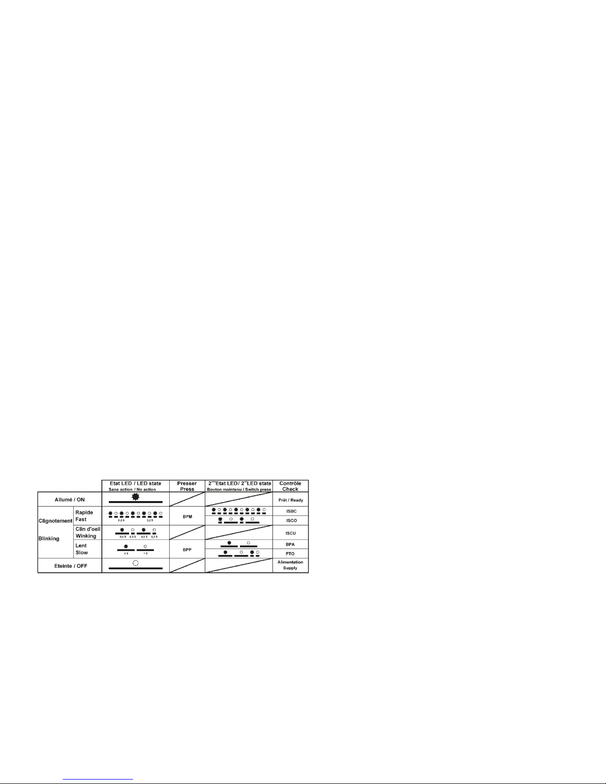
• VARIABLE SPEED VERSION
The flashing of the green light indicates which
element needs to be checked.
A rapidly flashing light indicates that either the base
(ISBC) or the lid (ISCO) presence sensor is posing a
problem. Press button I to determine which of these
two components needs to be checked. If the light
continues to flash the same way as before when you
press button I, check the lid arm sensor.
If, on the other hand, the light starts to flash more
slowly and asymmetrically (longer off than on),
check the lid sensor.
Asymmetrical flashing (longer on than off) means
that the bowl sensor needs to be checked (ISCU).
Slow flashing means that either the contact of the
STOP button (BPA) or the motor protector (PTO) is
posing a problem. Press button T to determine which
of these two components needs to be checked. If the
flashing does not change when you press button T,
check the contact of the STOP button.
If, on the other hand, the flashing becomes
asymmetrical (longer on than off), check the motor
overload protector.
For further details about the tests, see the previous
paragraph on dual-speed models.
Page 14
13
25/07/2017
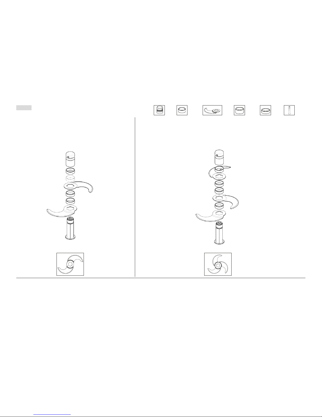
• 2-BLADE ASSEMBLY:
We recommend you use the two-blade assembly for processing
small amounts.
MONTAGE: • Fit the blades and spacers so that they are the right distance apart, according to the:
- type
- weight and
- volume of the foodstuffs to be processed.
WARNING: The plastic spacer goes below the nut + long spacer assembly.
Correct positioning of 2-blade assembly (top view) Correct positioning of 3-blade assembly (top view)
DISMANTLING: • Unscrew the screw nut.
• Remove the rings and blades.
• 3-BLADE ASSEMBLY (except for the Blixer® 8):
We recommend you use the 3-blade assembly for processing large quantities of more than half
the maximum limit indicated, with the exception of liquid or blended preparations for which
we strongly recommend you use the 2-blade assembly. For preparations of this kind, it is
recommended you use the first speed in order to obtain the best results.
Plastic
ring
Blade
Long ring
Screw
nut
Narrow
spacer
Blade
shaft
FITTING AND USING THE BLADE ASSEMBLY
Page 15
14
25/07/2017
Blixer® 10 dual-speed Three-phase appliance
Monophase or Three phase machine Blixer
®
10 V.V.
Monophase or Three phase machine Blixer
®
15 V.V.
Blixer
®
15 dual-speed Three-phase appliance
• WORKING HEIGHT
We recommend that you position the Blixer® 8 Blixer
®
8 V.V. - Blixer® 10 - Blixer® 10 V.V. on a
stable worktop so that the upper edge of the large
feed head is at a height of between 1.20 and 1.30
m.
We advise you to position your Blixer
®
15 - Blixer®
15 V.V. - Blixer
®
20 - Blixer® 20 V.V. on a stable
surface. There is no recommended working height
since this is a floor-standing model.
• NOISE LEVEL
The equivalent continuous sound level when
the machine is operating on no-load is less than
70 dB (A).
• ELECTRICAL DATA
Blixer® 8 dual-speed Three-phase appliance
Monophase or Three phase machine Blixer
®
8 V.V.
TECHNICAL
SPECIFICATIONS
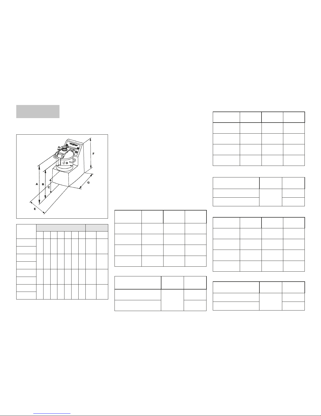
• WEIGHT & DIMENSIONS
Models
Dimensions (in mm) Weight (Kg)
A B C D E F G
Net Gross
Blixer
®
8
585 445 255 300 315 525 545 40 52
Blixer
®
8 V. V.
Blixer
®
10
660 520 280 300 345 600 560 45 57
Blixer
®
10 V.V.
Blixer
®
15
680 540 300 340 370 620 615 49 62
Blixer
®
15 V.V.
Blixer
®
20
760 620 315 340 380 700 630 75 88
Blixer
®
20 V.V.
Motor
Speed 1
(rpm)
Speed 2
(rpm)
Intensity
(Amp.)
230V/50 Hz / 3 1500
230 V = 8,5
400 V = 4,8
400V/50 Hz / 3 3000
230 V = 10
400 V = 5,5
220V/60 Hz / 3 1800
230 V = 10
400 V = 5,5
380V/60 Hz / 3 3600
230 V = 11
400 V = 6
Motor
Speed 1
(rpm)
Speed 2
(rpm)
Intensity
(Amp.)
230V/50 Hz / 3 1500
230 V = 13
400 V = 7
400V/50 Hz / 3 3000
230 V = 12
400 V = 6,5
220V/60 Hz / 3 1800
230 V = 11
400 V = 6,5
380V/60 Hz / 3 3600
230 V = 12
400 V = 7
Motor
Speed 1
(rpm)
Speed 2
(rpm)
Intensity
(Amp.)
230V/50 Hz / 3 1500
230 V = 10
400 V = 6
400V/50 Hz / 3 3000
230 V = 11
400 V = 6
220V/60 Hz / 3 1800
230 V = 10
400 V = 6
380V/60 Hz / 3 3600
230 V = 11
400 V = 6,5
Motor
Speed 1
(rpm)
Intensity
(Amp.)
200 - 240 V/50-60 Hz / 1
300
to
3500
21
200 - 240 V/50-60 Hz / 3 14,3
Motor
Speed 1
(rpm)
Intensity
(Amp.)
200 - 240 V/50-60 Hz / 1
300
to
3500
21,7
200 - 240 V/50-60 Hz / 3 11,6
Motor
Speed 1
(rpm)
Intensity
(Amp.)
200 - 240 V/50-60 Hz / 1
300
to
3500
21
200 - 240 V/50-60 Hz / 3 14,3
Page 16
15
25/07/2017
STANDARDS
Consult the declaration of compliance on page 2.
REMEMBER
Never try to override the locking and safety
systems.
Never insert an object into the container where
the food is being processed.
Never push the ingredients down with your
hand.
Do not overload the appliance.
Never switch the appliance on when it is
empty.
Blixer® 20 dual-speed Three-phase appliance
Monophase or Three phase machine Blixer
®
20 V.V.
SAFETY
This ROBOT-COUPE range of Blixer® is equipped
with a mechanical safety system and a motor
brake. Moreover, the machine will not operate
unless the bowl and lid are correctly positioned on
the motor base.
Once the lid is opened, the motor stops.
To restart the machine, simply close the lid and press
the green «On» switch.
WARNING
The blades are extremely sharp. Handle with
care.
Motor
Speed 1
(rpm)
Speed 2
(rpm)
Intensity
(Amp.)
230V/50 Hz / 3 1500
230 V = 16,3
400 V = 9,4
400V/50 Hz / 3 3000
230 V = 17,5
400 V = 10,1
220V/60 Hz / 3 1800
230 V = 16,3
400 V = 9,4
380V/60 Hz / 3 3600
230 V = 17,3
400 V = 10
Motor
Speed 1
(rpm)
Intensity
(Amp.)
200 - 240 V/50-60 Hz / 1
300
to
3500
24,8
200 - 240 V/50-60 Hz / 3 11,6
- Power shown on data plate.
These models are fitted with a thermal failsafe which
automatically switches the motor off if it is overloaded
or has been left running for too long.
If this happens, allow the machine to cool completely
before restarting.
Page 17
18
25/07/2017
Page 18
19
25/07/2017
Page 19
21
25/07/2017
Page 20
22
25/07/2017
Page 21
23
25/07/2017
Page 22
25
25/07/2017
Page 23
26
25/07/2017
Page 24
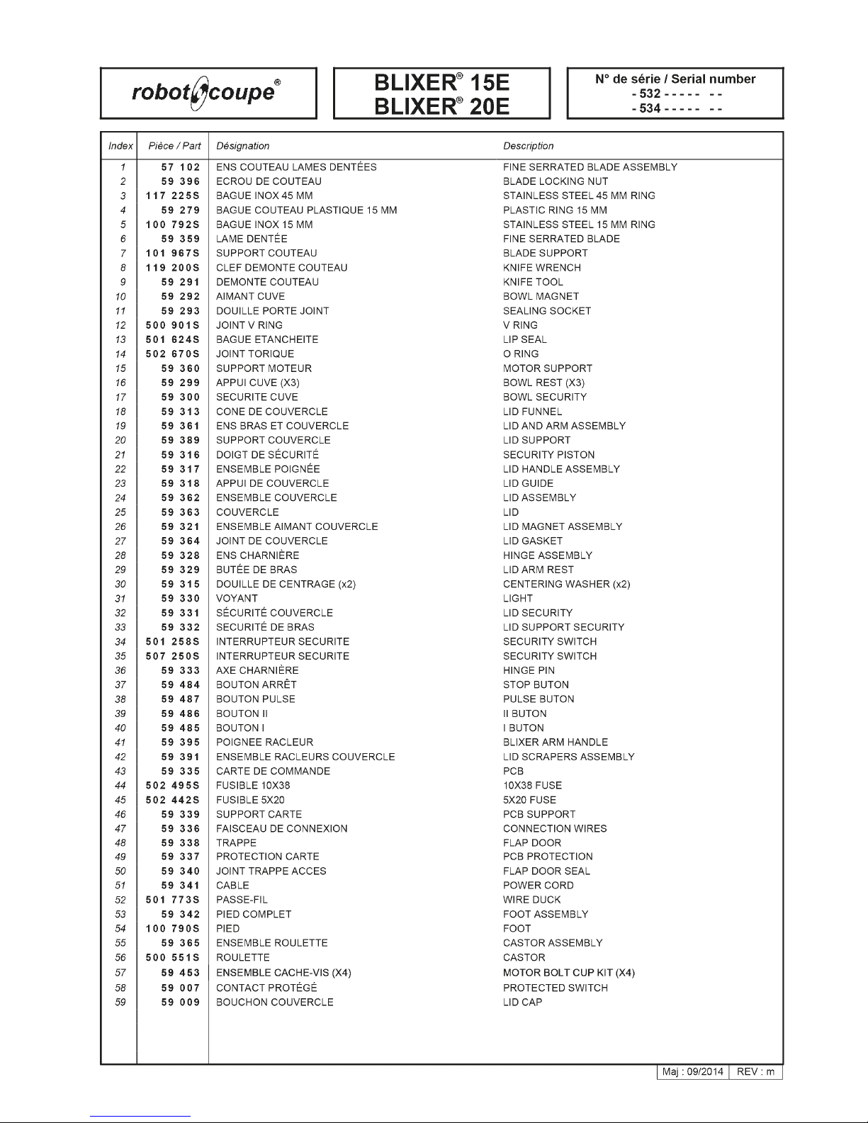
27
25/07/2017
Page 25
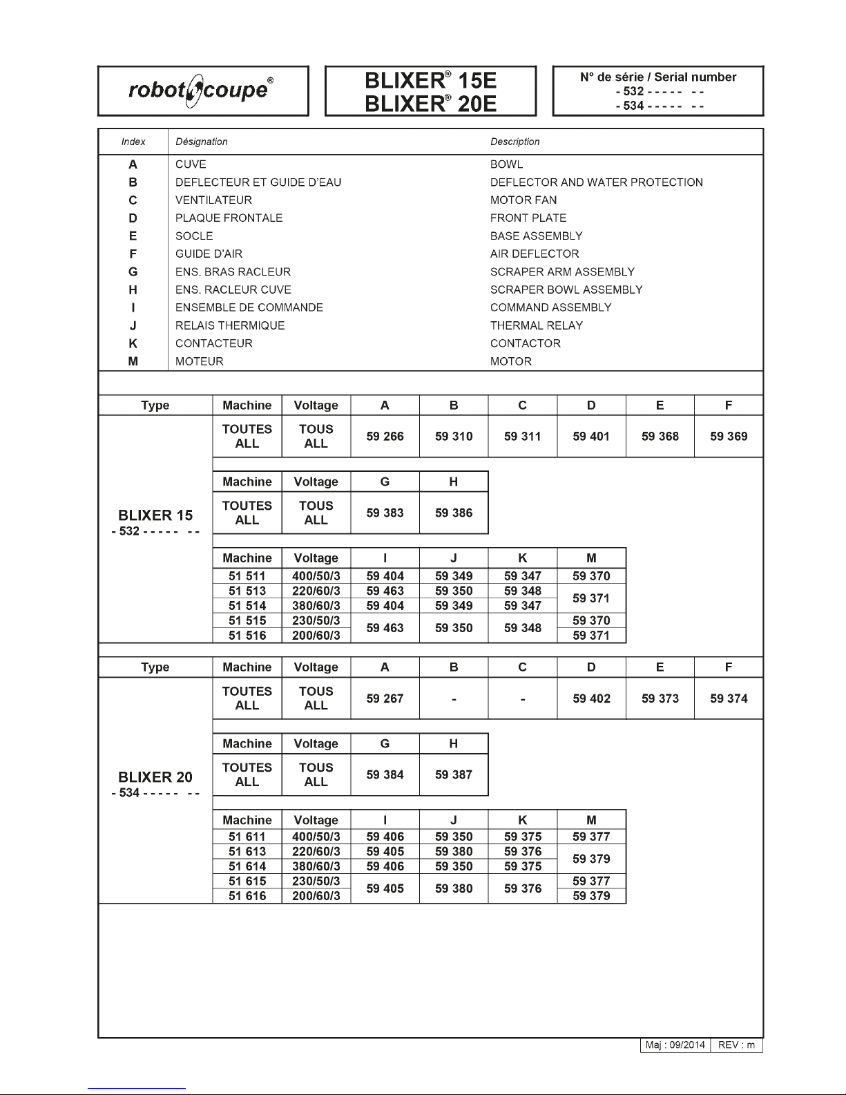
29
25/07/2017
Page 26
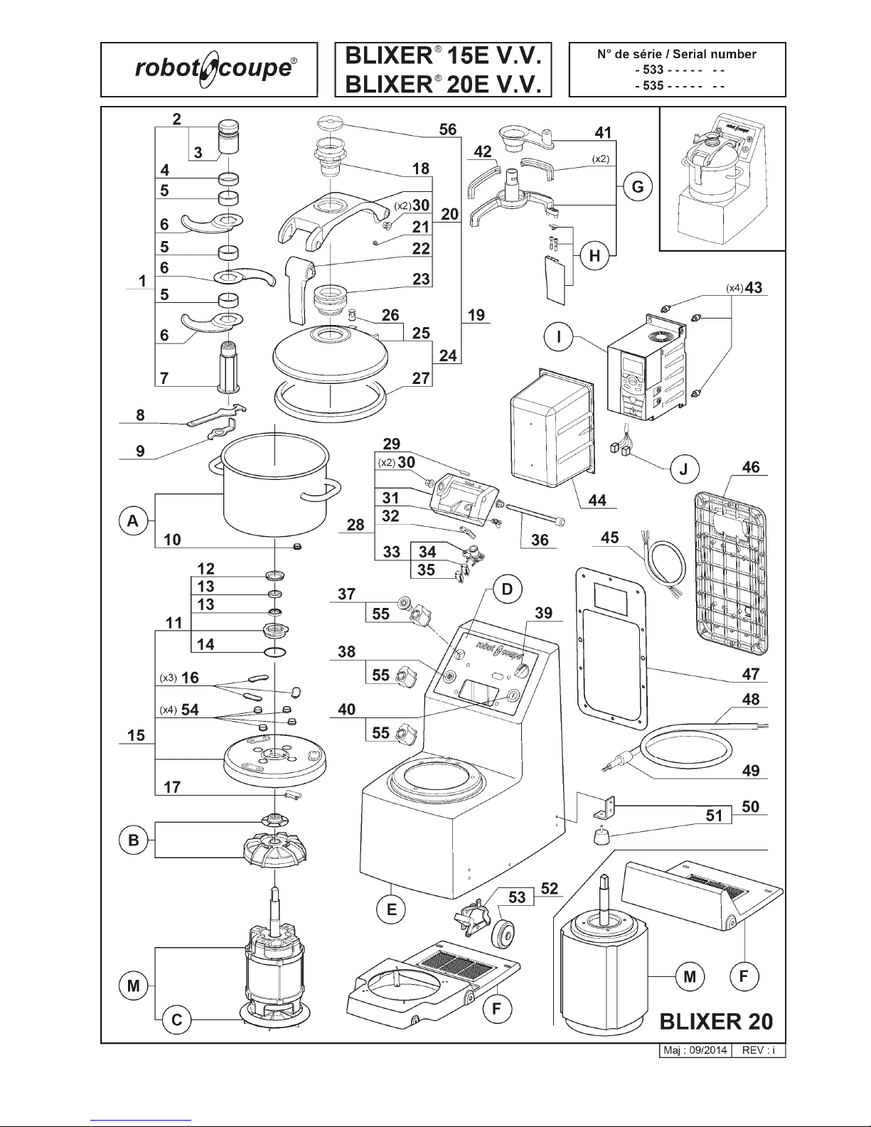
30
25/07/2017
Page 27
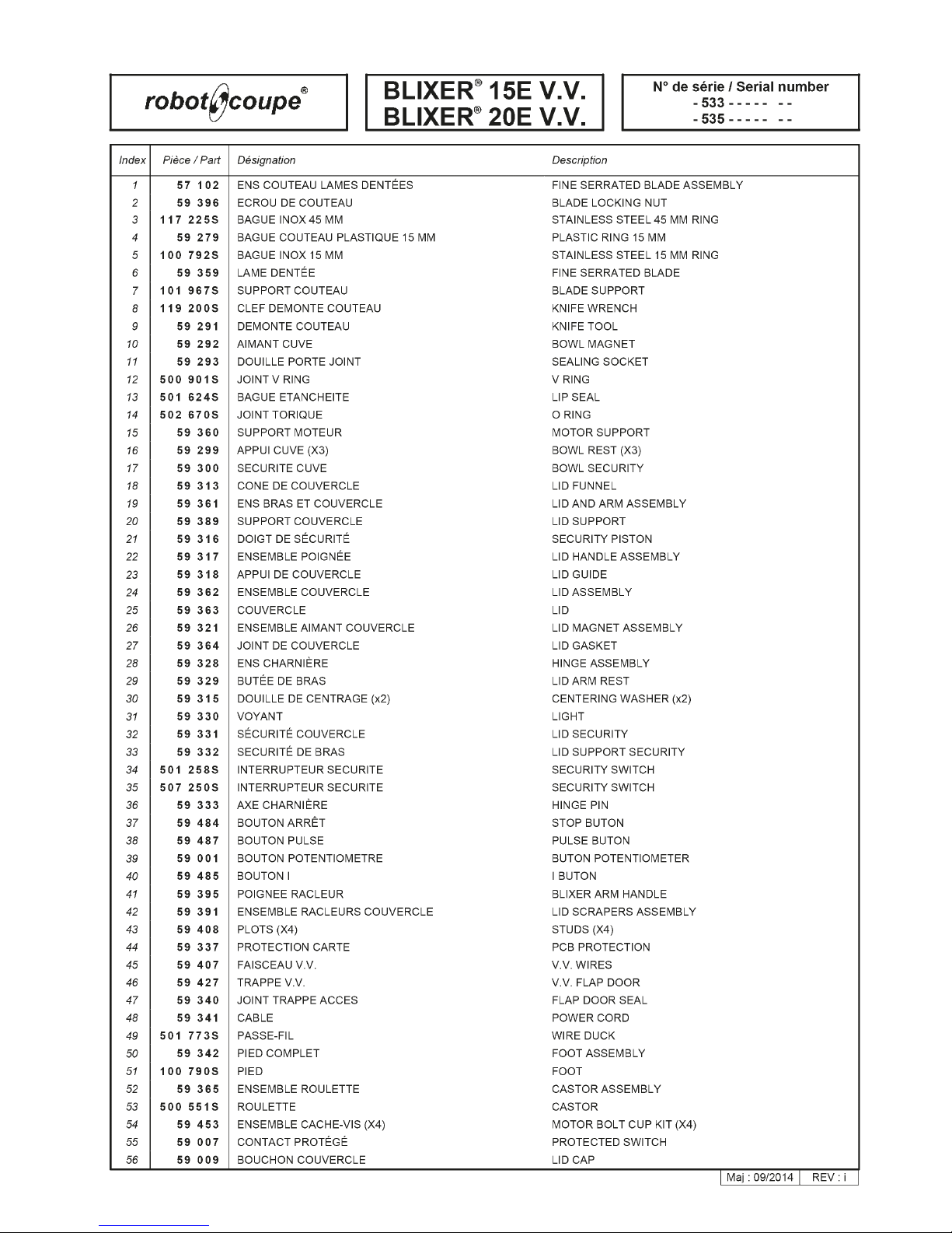
31
25/07/2017
Page 28

33
25/07/2017
Page 29
34
25/07/2017
Page 30
35
25/07/2017
Page 31
36
25/07/2017
Page 32
37
25/07/2017
Page 33

Réf. : 450 460 - 25/07/2017
Head Office, French,
Export and Marketing Department:
48, rue des Vignerons
94305 Vincennes Cedex- France
Tel.: 01 43 98 88 15 - Fax: 01 43 74 36 26
Email: [email protected]
Robot-Coupe U.K. LTD:
Fleming Way, Isleworth,
Middlesex TW7 6EU
Tel.: 020 8232 1800
Fax: 020 8568 4966
Email: [email protected]
Robot Coupe Australia Pty Ltd:
Unit 3/43 Herbert St
Artarmon NSW 2064 Australia
Tel.: (02) 9478 0300
Fax (02) 9460 7972
Email: [email protected]
 Loading...