

Page 1

meArm v0.4 Assembly Manual
The meArm is a pocket sized, open source, robotic arm designed by Ben Gran of Nottingham, England.
This assembly manual was created by Scott Pierce (www.spiercetech.com)
Original assembly instructions can be found at: www.instructables.com/id/Pocket-Sized-Robot-Arm-meArm-V04/
Hardware source files can be found at: www.thingiverse.com/thing:360108
Software source code can be found at: www.github.com/phenoptix/MeArm
Alternate source code can be found at: www.instructables.com/id/MeArm-software
meArm Assembly Manual v0.4
1
www.spiercetech.com
Page 2

Fasteners:
Here are a list of fasteners required to build the meArm v0.4. The profiles below are actual size.
Note: The Servo Screws and Servo Mount Screws reference in the assembly manual are included with
the servos and do not need to be purchased seperately.
10ea - M3 Nut
9ea - M3 x 6
10ea - M3 x 8
5ea - M3 x 10
7ea - M3 x 12
4ea - M3 x 20
meArm Assembly Manual v0.4
2
www.spiercetech.com
Page 3

PARTS LIST
ITEM
2
2
6
QTY
11
4
44
15
1
17
Base Plate
Rubber Foot
M3 x 20mm Screw43
M3 Nut
Pivot Servo Plate
Servo Retainer
9 Gram Servo
M3 x 8mm Screw28
PART NUMBER
2
3
3
3
2
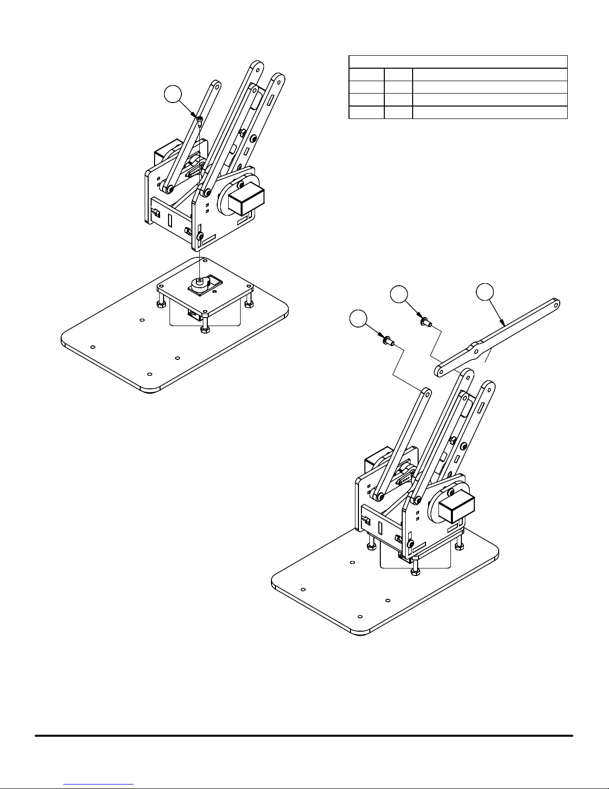
Step 1: Place (4) Rubber Feet on the bottom side of the Base Plate
Step 2: Insert (4) M3 x 20mm Screws through bottom side of the base plate
4
4
3
4
1
2
Step 3: Insert Servo into top side of Servo Retainer
Step 4: Insert Servo into bottom side of Pivot Servo Plate
Step 5: Insert (2) M3 x 8mm Screws through bottom of Servo
Retainer and thread them into the Pivot Servo Plate.
Note: The M3 x 8mm Screws will form their own threads into the
undersized Servo Retainer Plate. Do not over tighten the screws
or it will strip the mating holes.
5
7
6
8
8
4
Step 6: Thread (1) M3 Nut half way onto each of the (4) M3 x 20mm Screws
Step 7: Screw each of the M3 x 20mm Screws into the mating holes on the
Pivot Servo Plate until the end of the screw is flush with the top of
the Pivot Servo Plate
meArm Assembly Manual v0.4
Step 8: Tighten the M3 Nuts the rest of the way down onto
the Base Plate
3
www.spiercetech.com
Page 4

5
3
2
Step 9: Slide Servo Retainer over the bottom end of the Servo
Step 10: Slide Servo into the Arm Servo Plate, Left
Step 11: Insert (2) M3 x 8mm Screws into the Servo Retainer and then
screw them into the Arm Servo Plate, Left.
PARTS LIST
PART NUMBERQTYITEM
1
2
4
4
4
8
M3 Nut2
Servo Retainer1
9 Gram Servo13
M3 x 8mm Screw2
15
Left Arm Servo Plate
16
Parallel Linkage
Long Servo Arm17
1
M3 x 6mm Screw
19
Servo Single Arm
M3 x 12mm Screw210
111
Servo Screw
Servo Mount Screw112
7
10
10
1
Step 12: Insert (2) M3 x 12mm Screws into back side of
Left Arm Servo Plate
Step 13: Thread (1) M3 Nut onto each M3 x 12mm Screw
until nut is flush with the end of the screw
11
9
12
1
Step 14: Attach the Servo Arm to the Long Servo Arm
Extension using (1) of the (2) longer
screws supplied with the servo
6
Step 15: Press the Servo Arm assembly onto the Servo
and then gently rotate the Servo Arm clockwise
by hand until it stops. After it has stopped,
remove the Servo Arm assembly from the Servo
and position it as shown in the picture above.
Step 16: Insert Servo Screw that is supplied with the Servo
meArm Assembly Manual v0.4
8
Step 17: Insert (1) M3 x 6mm Screw into Parallel Linkage
and thread it into the Servo Arm Extension
4
www.spiercetech.com
Page 5

3
2
4
4
Step 18: Slide Servo Retainer over the bottom end of the Servo
Step 19: Slide Servo into Right Arm Servo Plate
Step 20: Insert (2) M3 x 8mm Screws into the Servo Retainer and then
screw them into the Left Arm Servo Plate
8
10
10
PARTS LIST
PART NUMBERQTYITEM
1
3
4
M3 Nut2
Servo Retainer12
1
9 Gram Servo
M3 x 8mm Screw2
Parallel Linkage15
M3 x 6mm Screw16
17
Servo Single Arm
M3 x 12mm Screw28
19
Right Arm Base Joint
1
Right Arm Servo Plate
Servo Screw111
Servo Mount Screw112
1
1
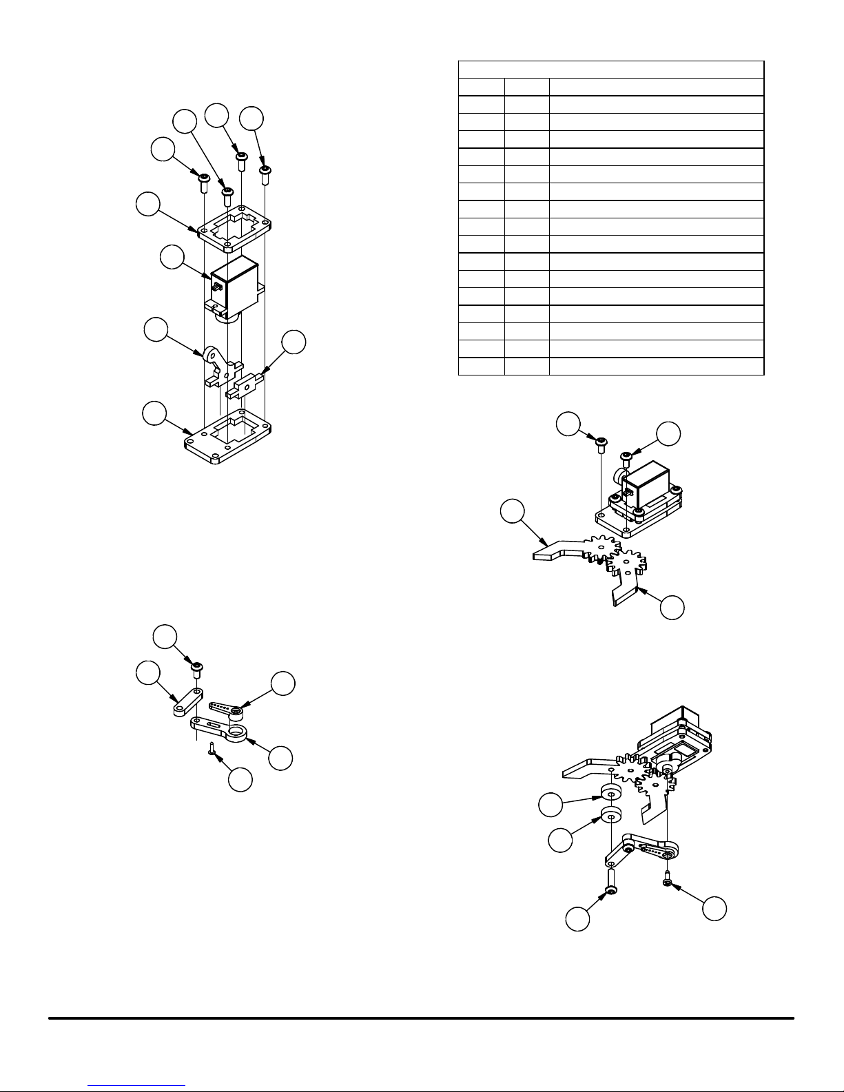
Step 21: Insert (2) M3 x 12mm screws into back side of
Right Arm Servo Plate
Step 22: Thread (1) M3 Nut onto each M3 x 12mm screw
until nut is flush with the end of the screw
11
8
7
Step 23: Attach the Servo Arm to the Right Arm Base Joint
using (1) of the Servo Mount Screws supplied with the
Servo.
5
9
12
Step 24: Press the Arm Base Joint assembly onto the Servo and then
gently rotate the Servo Arm counter clockwise by hand until it stops.
After it has stopped, remove the Arm Base Joint assembly from the
Servo and position it as shown in the picture above.
Step 25: Insert the Servo Arm Screw that is supplied with the Servo
meArm Assembly Manual v0.4
6
Step 26: Insert (1) M3 x 6mm Screw into the Parallel Linkage
and thread it into the Right Arm Servo Plate
5
www.spiercetech.com
Page 6

3
1
2
Step 27: Insert (1) M3 x 6mm screw through the Left Arm
Mount Tab and thread it into the Left Arm Base Joint
ITEM
2
QTY
11
Left Arm Mount Tab
1
M3 x 6mm Screw
13
Left Arm Base Joint
14
Arm Bottom Plate
15
Servo Double Arm
Servo Mount Screw26
PARTS LIST
PART NUMBER
5
4
6
6
Step 28: Attach Servo Arm to the Arm Bottom Plate using (2)
Servo Mount Screws supplied with the Servo.
meArm Assembly Manual v0.4
6
www.spiercetech.com
Page 7

3
3
Step 29: Insert (2) Arm Base Crossmembers into the Left Arm
Servo Plate. Do not tighten screws yet.
PARTS LIST
PART NUMBERQTYITEM
M3 Nut21
M3 x 12mm Screw22
Arm Base Crossmember23
4
1
Main Arm Cross Web
Step 30: Insert Left Arm Mount Tab assembly into the slots of
the Arm Base Crossmembers
1
2
Step 32: Join the Main Arm Cross Web to the Left Arm Base Joint
Step 33: Insert (1) M3 x 12mm Screw into the Left Arm Base Joint
then tighten nut, securing the Left Arm Base Joint to the
Main Arm Cross Web
4
Step 31: Insert the Arm Bottom Plate into the tabs and
slots of the Left Arm Servo Plate and the Arm
Base Crossmembers
1
2
Step 34: Join the Right Arm Servo Plate assembly to the rest
of the assembly from the previous steps using (1) M3
Nut and (1) M3 x12mm Screw.
meArm Assembly Manual v0.4
7
www.spiercetech.com
Page 8
PARTS LIST
PART NUMBERQTYITEM
2
2
M3 x 6mm Screw21
1
Servo Screw
13
Left Wrist Joint
Step 35: Attach the Arm Assembly to the Base assembly and then
secure them together using the included Servo Screw.
1
1
3
meArm Assembly Manual v0.4
Step 36: Attach the Left Wrist Joint to the Parallel Linkage and the Left Arm
Base Joint using (2) M3 x 6mm Screws
8
www.spiercetech.com
Page 9

PARTS LIST
ITEM
2
3
5
QTY
11
Parallel Linkage
M3 x 6mm Screw12
13
Parallel Linkage Connector
14
Right Wrist Joint
Spacer15
M3 x 10mm Screw26
PART NUMBER
1
4
6
6
Step 37: Attach (1) Parallel Linkage to the Parallel Linkage Connetor using (1) M3 x 6mm Screw
Step 38: Attach the Parallel Linkage Connector to the Right Wrist Joint and the Left Arm Base Joint using (1) M3 x 10mm Screw
Step 39: Attach the last hole of the Parallel Linkage Connector to the Parallel Linkage on the Right Arm Servo Plate using
(1) M3 x 10mm Screw. Make sure to place (1) Spacer between the Parallel Linkage Connector and the Parallel Linkage.
meArm Assembly Manual v0.4
9
www.spiercetech.com
Page 10
PARTS LIST
ITEM
12
12
12
7
11
5
12
4
QTY
11
Left Gripper
Right Gripper12
Gripper Actuating Arm13
14
Left Wrist Attachment
15
Right Wrist Attachment
16
Clamp Bottom Servo Mount
17
Clamp Top Servo Mount
18
Short Servo Arm
Servo Screw19
110
Servo Single Arm
9 Gram Servo111
M3 x 8mm Screw412
M3 x 6mm Screw313
Servo Mount Screw114
M3 x 12mm Screw115
Spacer216
PART NUMBER
6
Step 40: Slide the Servo into the Clamp Top Servo Mount.
Step 41: Slide the Right and Left Wrist Attachments into the Clamp Top
Servo Mount as show.
Step 42: Slide the Clamp Bottom Servo Mount over the Servo.
Step 43: Insert (4) M3 x 8mm Screws into the Clamp Top Servo Mount and
thread them into the Clamp Bottom Servo Mount.
13
3
14
Step 45: Attach (1) Servo Single Arm to the Short Servo Arm
using (1) Servo Mount Screw
Step 46: Attach the Gripper Actuating Arm to the Short Servo Arm
using (1) M3 x 6mm Screw
10
8
13
2
Step 44: Attach the Left Gripper and Right Gripper to the Servo
assembly from the previous step using (2) M3 x 6mm
Screws
16
16
13
1
meArm Assembly Manual v0.4
10
15
Step 47: Attach the Gripper Arm assembly from the previous step
to the Servo assembly using (1) 9 Gram Servo Screw,
(1) M3 x 12mm Screw, and (2) Spacers
9
www.spiercetech.com
Page 11
ITEM
2
2
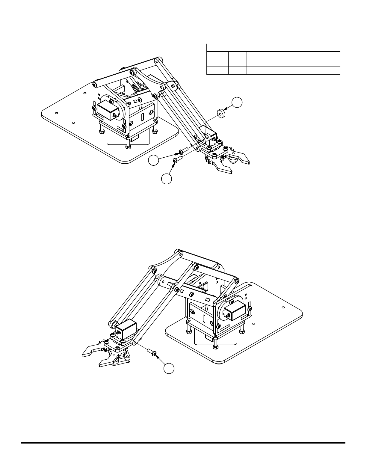
Step 48: Attach the right side of the Gripper assembly to the rest of the meArm using
(2) M3 x 10mm screws and (1) Spacer
QTY
1
PARTS LIST
PART NUMBER
Spacer11
M3 x 10mm Screw32
Step 49: Attach the left side of the Gripper assembly to the rest of the meArm using
(1) M3 x 10mm screw
meArm Assembly Manual v0.4
2
11
www.spiercetech.com
 Loading...