

Robostar Co., Ltd
Robostar Robot Controller Manual
www.robostar.co.kr
√
RRoobboossttaarr RRoobboot
t
N11 SSeerriieess
N
Deevviiccee
D
Option Module
- DeviceNet
Oppttiioonn
O
Neett
N

www.robostar.co.kr
Robostar Co., Ltd
Robostar Robot Controller Manual
√
RROOBBOOSSTTAARR RROOBBOOT
T
N11 SSeerriieess
N
Deevviiccee
D
Option Module
- DeviceNet
Oppttiioonn
O
Neett
N

Copyright ⓒ ROBOSTAR Co., Ltd 2012
The copyright of this user manual is owned by Robostar Co., Ltd. No part of this manual may be
used in any form or by any means without Robostar Co., Ltd. Specifications are subject to change
without prior notice.

Product Warranty
Address and Contact Details for Robostar Co., Ltd
Head Office and Factory
700, Suin-ro, Sangnok-gu,
Ansan-City, Gyeonggi-do, Republic of
South Korea (426-220)
2
nd
Factory
108, Saneop-ro, Gwonseon-gu,
Suwon-City, Gyeonggi-do, Republic of
South Korea (441-813)
Service Inquiry and Product Inquiry
- Sales Inquiry
TEL. 031-400-3600
FAX. 031-419-4249
- Customer Inquiry
TEL. 1588-4428
www.robostar.co.kr
Regarding Product Warranty
Robostar products are manufactured under strict quality control and all Robostar products
are covered under one year warranty from the date of manufacture. We offer free services
during this warranty period only for mechanical breakdowns caused by faults by Robostar or
breakdowns which arise from problem in design and manufacturing faults during normal use.
No free service is provided to the following occasions.
(1) After the warranty period expires
(2) Mechanical troubles caused by inappropriate repairs, alteration, movement and other negligent
handling directed by your company or a third party.
(3) Mechanical troubles caused by use of other products than the ones assigned by our company,
such as components and grease
(4) Mechanical troubles caused by fires, disasters, earthquakes, storm and flooding and other natural
disasters
(5) Malfunction due to use in environment beyond our product specifications, such as in excretions
and flooding
(6) Malfunction due to normal wear of consumable parts
(7) Malfunction due to lack of carrying out maintenance work checklist as listed in User Manual and
Handling Manual
(8) Damage not included in robot repair costs
i Robostar Co., Ltd

Composition of User Manual
CCoommppoossiittiioonn ooff UUsseerr MMaannuuaall
The User Manual of this product is composed of the following. If this is the first time to use
this product, fully understand each and every detail in the manual before use.
DeviceNet
Explains how to connect a connector to N1 series using DeviceNet communication modules as
well as how to use it.
ii Robostar Co., Ltd

Table of Content
Table of Contents
CHAPTER 1. OVERVIEW ....................................................................................................................................... 1-1
1.1 WHAT IS A DEVICENET OPTION BOARD? .......................................................................................................... 1-1
1.2 SYSTEM CONFIGURATION ................................................................................................................................. 1-1
CHAPTER 2. FUNCTION ........................................................................................................................................ 2-1
2.1 SPECIFICATIONS OF DEVICENET OPTION BOARD .............................................................................................. 2-1
2.2 CHARACTERISTICS AND FUNCTIONS OF DEVICENET ......................................................................................... 2-1
CHAPTER 3. SPECIFICATIONS ............................................................................................................................ 3-1
3.1 DEVICENET SPECIFICATIONS ............................................................................................................................ 3-1
3.2 STATUS DISPLAY LED ...................................................................................................................................... 3-2
3.3 STATION NUMBER SETTING .............................................................................................................................. 3-3
3.4 DISPLAY OF COMMUNICATION POWER AND COMMUNICATION LINE ................................................................. 3-3
3.5 I/O SIZE SETTING ............................................................................................................................................ 3-5
3.6 CABLE SPEC ..................................................................................................................................................... 3-6
3.7 HOW TO INSTALL HARDWARE ........................................................................................................................... 3-1
CHAPTER 4. INSTALLATION AND OPERATION SETTING ........................................................................... 4-1
4.1 HOW TO CONNECT DEVICENET FIELD NETWORK CABLE ................................................................................. 4-1
4.2 CONTROLLER SETTING ..................................................................................................................................... 4-2
4.2.1 FIELD BUS(DeviceNet) Setting............................................................................................................... 4-2
4.2.2 USER I/O Setting ..................................................................................................................................... 4-4
4.3 PLC DATA TRANSFER SPEED ................................................................ ................................ ............................ 4-5
CHAPTER 5. EXAMPLES OF DEVICENET SETTING ...................................................................................... 5-1
5.1 EXAMPLES OF AB PLC RSNETWORK SETTING ................................................................................................ 5-1
CHAPTER 6. MEMORY MAPPING ....................................................................................................................... 6-1
6.1 N1 CONTROLLER DATA MAPPING ..................................................................................................................... 6-1
6.1.1 N1 Series System Input #1 ........................................................................................................................ 6-2
6.1.2 N1 Series System Input #2 & FIELDBUS INPUT#1 ................................................................................ 6-3
6.1.3 N1 Series FIELDBUS INPUT #2 ............................................................................................................. 6-3
6.1.4 N1 Series System Output #1 ..................................................................................................................... 6-3
6.1.5 N1 Series FIELDBUS Output #2 ............................................................................................................. 6-4
6.2 PRECAUTIONS FOR USE IN N1 SERIES SYSTEM MODE ...................................................................................... 6-4
iii Robostar Co., Ltd

Table of Content
6.3 N1 SERIES FIELDBUS(CC_LINK) TIMING DIAGRAM ........................................................................................ 6-5
6.3.1 Operation in AUTO RUN MODE ............................................................................................................ 6-5
6.3.2 JOB Program Change during JOB Operation ......................................................................................... 6-7
6.3.3 JOB Program Change after Completing JOB Program .......................................................................... 6-9
6.3.4 JOB Program START after Disabling Alarm ......................................................................................... 6-11
6.3.5 JOB Program Restart after Disabling Alarm ......................................................................................... 6-13
6.3.6 SERVO OFF ........................................................................................................................................... 6-15
6.3.7 Rebooting ............................................................................................................................................... 6-17
6.3.8 MODE(AUTO, STEP, JOG) Change ..................................................................................................... 6-19
6.3.9 STEP MODE .......................................................................................................................................... 6-21
6.3.10 Operation in JOG MODE ...................................................................................................................... 6-23
6.3.11 Forward Operation in JOG MODE ....................................................................................................... 6-25
6.3.12 Read RPM, TRQ..................................................................................................................................... 6-27
6.3.13 Read Current Position ........................................................................................................................... 6-28
6.3.14 Read GLOBAL Point .............................................................................................................................. 6-29
6.3.15 Write GLOBAL Point ............................................................................................................................. 6-31
6.3.16 Read GLOBAL Integer ........................................................................................................................... 6-33
6.3.17 Write GLOBAL Integer .......................................................................................................................... 6-34
6.3.18 Read GLOBAL Float .............................................................................................................................. 6-35
6.3.19 Write GLOBAL Float ............................................................................................................................. 6-36
iv Robostar Co., Ltd

Overview
Chapter 1. Overview
1.1 What is a DeviceNet Option Board?
A DeviceNet Option Board is a board in charge of DeviceNet field network system communication
of Robostar N1 controller. N1 controller allows the use of a DeviceNet Option Board to enable
communicating with systems such as PC or PLC using DeviceNet protocols. DeviceNet, one of
fieldbus communication methods getting the most spotlight over recent years, is considered the
most successful technology among a variety of fieldbuses due to its short system response time
and high reliability through the use of CAN (Controller Area Network) protocols.
1.2 System Configuration
The upper network can be interfaced with a DeviceNet master station such as PC or PLC, while a
master station utilizes DeviceNet field network to communicate with sub-slave stations.
Fig. 1.1 DeviceNet System Configuration
1-1 Robostar Co., Ltd
DeviceNet
connections
Connector
Pluggable connector(5.08mm, 5-pin)
Data Transfer Method
CAN(Controller Area Network)
Transfer Cable
DeviceNet dedicated cable (4-wire shield cable)
Withstand Voltage
500VDC
Terminating Resistance
120 Ohm
Communications
Communication Protocol
ODVA 2.0
Communication Speed
125/250/500Kbaud (Set automatically depending on
master)
Product Code
0x10/0x11
Product Type
0(Generic)
Vendor ID
1055
Electrical
Communication Power
11~25V DC
Communication Current
Below 30mA
Control Power
5V DC(Provided from Robostar controller)
Environment
Operating Temperature
0 ~ 40℃
Storage Temperature
-15 ~ 60℃
Operating Humidity
20~80% PH
Max Number of
Stations to use
64 stations (0-63)
Communication
Distance per
Speed
125Kbps
500m
250Kbps
250m
500Kbps
100m
Data
Transmit/Receive
Methods
Explicit Message(Parameter input/output data)
Polled I/O Message(Real-time input/output data)
Transmit/Receive
Length
Explicit Message: Flexible depending on parameter length
Polled I/O Message: Max 32Byte(Default:8Byte)
Device Type
Group2 Only Server(Predefined Master/Slave Connection Set)
Chapter 2. Function
2.1 Specifications of DeviceNet Option Board
Function
2.2 Characteristics and Functions of DeviceNet
2-1 Robostar Co., Ltd

Specifications
Signal
Connector
Description
V- 1 Communication Power, Ground(0V)
CAN_L
2
Communication Signal, Low
Drain
3
Shield
CAN_H
4
Communication Signal , High
V+ 5 Communication Power , +24V DC
① ② ③ ④ ⑤
Program Change
NS_R
NS_G
MS_G
MS_R
Station 1x
Rotary Switch
Station 10x
Rotary Switch
I/O Size
V+
CANH
Drain
CANL
V-
DeviceNet
Communication
Chapter 3. Specifications
3.1 DeviceNet Specifications
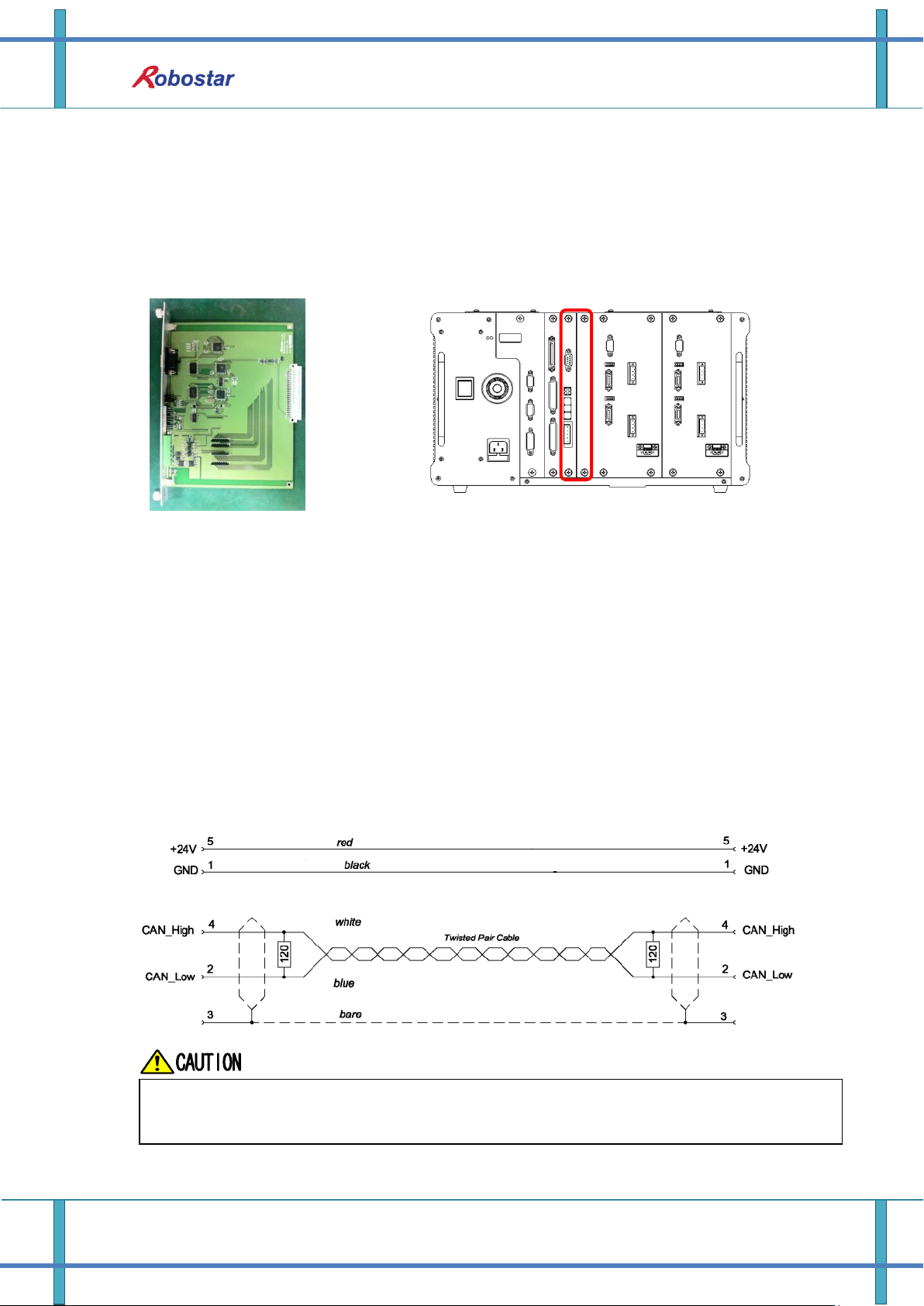
DeviceNet Option Board is connected to the external fieldbus through a 5-pin connector and
connected to Robostar N1 controller through a built-in Dual_Port memory. DeviceNet Option Board
consists of DeviceNet 5-pin connector, module status display LED, network status display LED, prefix
setup switch, I/O SIZE setup switch, and RS-232 connector(DB9).
Fig. 3.1 DeviceNet Board Block-diagram
Table 3.1 DeviceNet Connector Setting
3-1 Robostar Co., Ltd

Specifications
LED Status
Description
NS_R(Red)
NS_G(Green)
Off Off
DeviceNet Option Board not On-line.
-.Board not connected to master yet.
-. Power to Module status display not provided with LED OFF.
Off
On
Board is On-line, connecting normally to master.
Off
Blinking
Board is On-line by passing check for a duplicate node but not in
communication with master.
Blinking
Off
I/O Connection(Poll I/O) in Time-Out.
On
Off
Board unable to connect to network. (ID duplicated or Bus-Off)
LED Status
Description
MS_R(Red)
MS_G(Green)
Off
Off
Power not provided.
Off
On
Board under normal operation.
Off
Blinking
Board is on Stand-by or a certain error occurred in the course of
initializing network parameters.
Blinking
Off
Error generated on Board which is likely to go back to normal.
On
Off
Error generated on Board which is unable to go back to normal.
3.2 Status Display LED
DeviceNet Option Board has two LEDs – a module status display LED(MS_R, MS_G) indicating the
Board status and a network status display LED(NS_R, NS_G) indicating the communication status.
Table 3.2 Network Status Display LED
Table 3.3 Module Status Display LED
LED Check
When DeviceNet Option Board is powered, LED check is done with the following procedure.
1. Turn all LEDs Off
2. Turn all Green LEDs On(25ms)
3. Turn all Red LEDs On(25ms)
4. Turn all LEDs Off
5. Under normal operation
3-2 Robostar Co., Ltd

Specifications
Communication Power
Connect to Terminal 1 (-V, Black) and 5 (+V, Red).
Communication Line
Connect to Terminal 2(CANL, Blue) and 4 (CANH, White).
3.3 Station Number Setting
Use the Station 10x Rotary Switch and Station 1x Rotary Switch in Fig. 3.1 ② and change into
Station Number set in Master to have communication with DeviceNet Master. Rotary Switch makes
use of a decimal number so you can set a tenth place with 10x Rotary Switch and the first place with
1x Rotary Switch.
Fig. 3.2 Examples of Station Number Setting
Station Number setting can be done from Station 0 to 64, where the remote device station where
DeviceNet Option Board belongs is capable of setting from Station 1 to 64. Fig. 3.2 shows an
example set by 17 stations. When resetting a prefix, be sure to change the power from OFF->On.
3.4 Display of Communication Power and Communication Line
Fig. 3.3 Connector Pin Layout
3-3 Robostar Co., Ltd

Specifications
Measured Value
Measures
Below 50 Ω
Possible error is on the board connected. Remove error by checking the
terminating resistance.
50 – 70 Ω
Under normal condition
70 – 125 Ω
Either CANH or CANL disconnected, or the terminating resistance is installed
only at one end.
Over 125 Ω
The terminating resistance is not installed, or CANH or CANL disconnected.
Terminating resistance (120 Ω) should be installed in termination of communication.
V-
CAN
L
SLD
V+
CAN
H
Upon completion of wiring, check that the wiring has been properly conducted by measuring the
resistance value on both ends (CANH, CANL) of the communication line.
Fig. 3.4 Resistance Measurement
See Table 3.4 for reference for details about the resistance values measured.
Table 3.4 Resistance Measurement for Presence of Connection Error
Terminating resistance (120Ω, ±1%) is connected between Connector CANL(2PIN) and CANH(4PIN).
For how to connect, refer to “Fig. 3.5 How to Connect Terminating Resistance”.
Fig. 3.5 How to Connect Terminating Resistance (120Ω)
3-4 Robostar Co., Ltd

Specifications
Input/Output Data Size Setting Value
Value
IN Data Size
OUT Data Size
0
48 Kbyte
48 Kbyte
1
46 Kbyte
40 Kbyte
2
8 Kbyte
8 Kbyte
Values other
than the above
values
Error
3.5 I/O SIZE Setting
This product allows an easy I/O SIZE setting with a choice of switches. I/O SIZE can change
depending on the location of Switch 3. If Switch3 is positioned in 0, I/O SIZE is 48X48 SIZE and if 1,
I/O SIZE is 46X40 for use.
Fig. 3.6 Example of Data Size Setting Table 3.5 Input/Output Size Setting Value
3-5 Robostar Co., Ltd

3.6 Cable Spec
Specifications
Fig. 3.7 Thick Cable
Fig. 3.8 Thin Cable
- When using 24 Volts DC on a thick cable or flat cable, the maximum for use is 8A but
NEC Class 2 requirements permit only 4A. (Applies only to North America)
- A maximum of 3A is possible when using 24 Volts DC on a thin cable.
3-6 Robostar Co., Ltd
Installation and Operation Setting
For FieldBus network cable, use a certified DeviceNet cable.
When using a non-dedicated cable, it may lead to malfunction due to noise.
3.7 How to Install Hardware
Take the following procedure to be able to use DeviceNet Option Board of N1 series controller.
1) Turn power OFF.
2) Attach DeviceNet Option Board to PCI slot on N1 Controller.
Fig. 4.1 How to Install Option Board
3) Turn power back ON.
Chapter 4. Installation and Operation Setting
4.1 How to Connect DeviceNet Field Network Cable
A STL(Z) 950 5-pin OPEN Connector is used for how to connect between Cable and Connector
DeviceNet Option Card, therefore a screw driver is used to fix 4 wires on DeviceNet field network ---
V+(Red), CANH(White), CANL(Blue), V-(Black). Basically use a certified DeviceNet cable. For wiring
between cable and Connector, refer to “Fig. 4.2”, “Fig. 3.3”.
Fig. 4.2 How to Connect Network Cable
4-1 Robostar Co., Ltd

Installation and Operation Setting
4
L
F3
1
Q
<MAIN MENU>
1. JOB 2. RUN
3. HOST 4. PARA
5. ORIGIN 6. I/O
7. SYSTEM 8. GPNT
9. INT/FLT A. ALARM
SELECT #
<PARAMETER>
NO TYPE
*CH1 XYZW
CH2 XY_TEST
SEL INFO PUB EXIT
<PUBLIC PARAMETER>
1: HW CONF 2: PALLET
3: PLC 4: ETC
group #
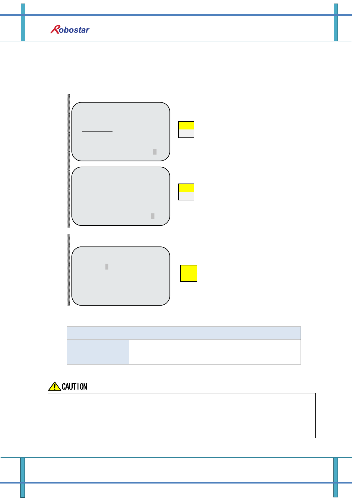
Open initial MAIN screen
Select 4: PARA
Select 1:HW CONF
Open PUBLIC PARAMETER group screen
Press F3 button to move to PUB
4.2 Controller Setting
To use DeviceNet from N1 Controller, the following Software setup is required.
4.2.1 FIELD BUS(DeviceNet) Setting
1. Setting Procedure
Step1. Move to PUBLIC Parameter screen
4-2 Robostar Co., Ltd

2
R
ESC
ENTER
1
Q
2
R
4
L
<HW CONF - COM>
COMMUNICATION SET
1: RS232C
2: FIELD BUS
3: LINE SEPARATOR
group #
Select 2: FIELD BUS
Select 2:COMM
<PUBLIC-HW CONF(0)>
1: TMR 2: COMM
3: I/O 4: D-MAN
5: SVON 6: A I/O
item #
<COM-FDBUS >
1: CARD
2: USER I/O
3: PROFIBUS ENDIAN
4: MAP EXTENTION
Input: ■
Select 1: CARD
<FDBUS-CARD>
OPT COM CARD
1: NONE 2: CC-LINK
3: PROFIBUS 4: D-NET
Updata OK?(ENT/ESC) ■
Press ESC and then ENTER to save
<FDBUS-CARD>
OPT COM CARD
1: NONE 2: CC-LINK
3: PROFIBUS 4: D-NET
Selected : CC-LINK■
Select 2: D-NET
When there is no DeviceNet B/D, a message “Not Card!” comes up at bottom of
T/P screen and fails to be saved.
Step2. Move to FIELD BUS screen
Installation and Operation Setting
Step3. OPTION CARD setup screen
4-3 Robostar Co., Ltd
2
R
ENTER
2
R
Item
Description
SYS USER I/O
Input/output using USER I/O of N1 System IO B/D
FIELDBUS USER I/O
Input/output using USER I/O in Field Bus card
<COM-FDBUS>
1: CARD
2: USER I./O
3: PROFIBUS ENDIAN
4: MAP EXTENTION
input #
Select 2: USER I/O
<FDBUS-USER I/O>
USER IN/OUT SEL
USER IO : SYS U I/O
Select SYS U I/O” or “FIELD U I/O
<HW CONF - COM>
COMMUNICATION SET
1: RS232C
2: FIELD BUS
3: LINE SEPARATOR
group #
Open COMM screen
Select 2: FIELD BUS
Data(USER I/O area) input/output are restricted due to communications in setting SYS
USER I/O.
When setting FIELDBUS USER I/O, Data(User I/O) input/output via I/O Board are restricted.
For further details about User I/O, refer to “Handling Manual 3.3.6”.
4.2.2 USER I/O Setting
1. Setting Procedure
Step1. Move to USER I/O screen
Installation and Operation Setting
Step2. USER I/O setup screen
When using a Field Bus card, a method of using USER I/O is set.
4-4 Robostar Co., Ltd
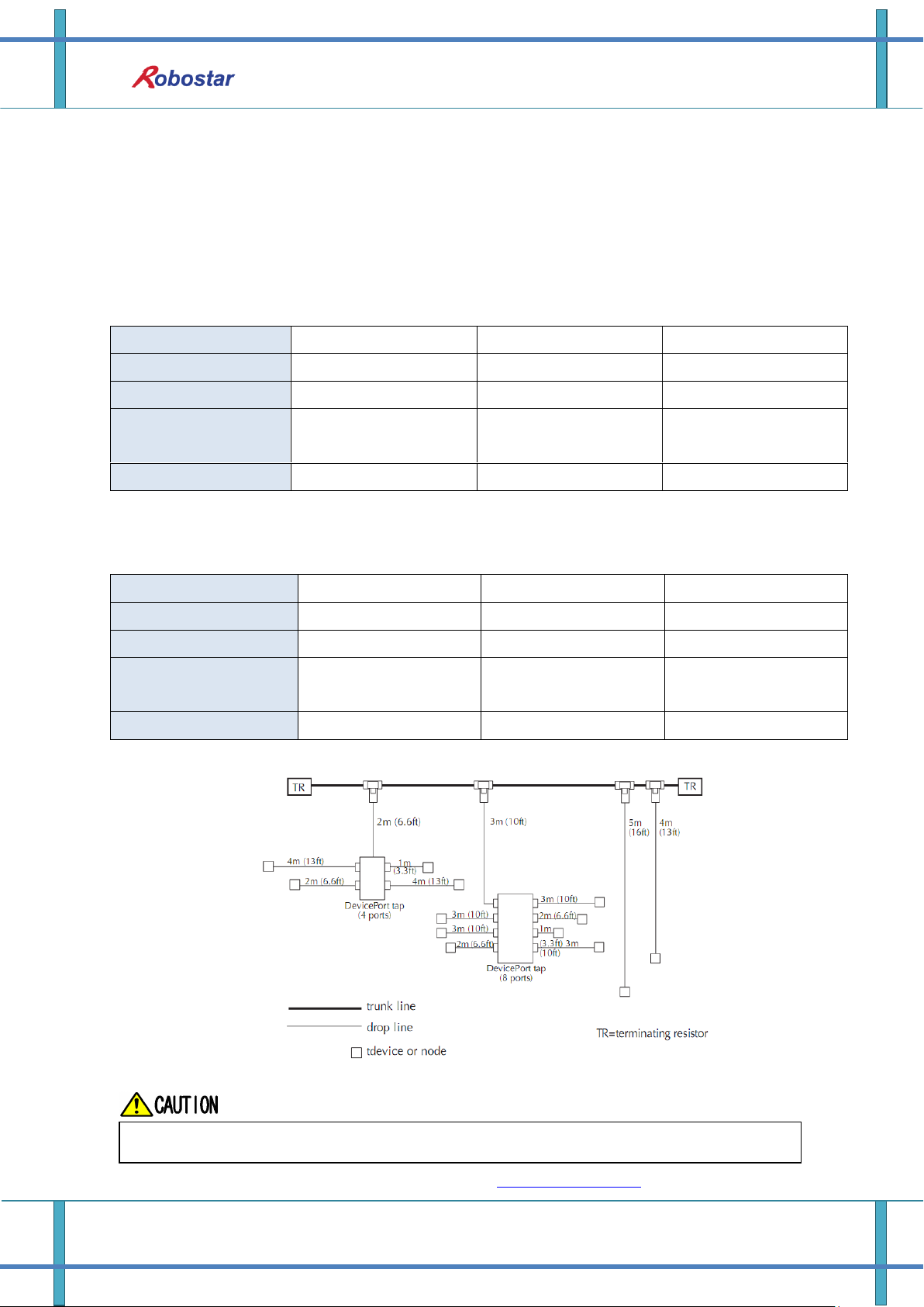
Installation and Operation Setting
Transfer Rate
125 Kbps
250 Kbps
500 Kbps
Transfer Distance
500m
250m
100m
Longest Drop Length
6m
6m
6m
Cumulative Drop
Length
153m
77m
38m
Number of Nodes
64
64
64
Transfer Rate
125 Kbps
250 Kbps
500 Kbps
Transfer Distance
100m
100m
100m
Longest Drop Length
6m
6m
6m
Cumulative Drop
Length
153m
77m
38m
Number of Nodes
64
64
64
DeviceNet communication speed can be set on a PLC.
4.3 PLC Data Transfer Speed
When transmitting data from PLC, a maximum of 10ms delay time may occur. As the Controller
takes20ms for data scanning time, an accurate operation may not be guaranteed if a data value is
changed for less than 20ms.
Thick Trunk
Thin Trunk
Fig. 4.3 Example of Drop Line
For other details about DeviceNet, refer to ODVA (WWW.ODVA.OR.KR).
4-5 Robostar Co., Ltd
Examples of DeviceNet Setting
Chapter 5. Examples of DeviceNet Setting
5.1 Examples of AB PLC RSNetwork Setting
How to set DeviceNet stated in this Manual made use of PLC model 1756 Compactlogix made by AB
as a PLC, and used RSLinx, RSNetworx and RSLogix 5000 made by AB as software.
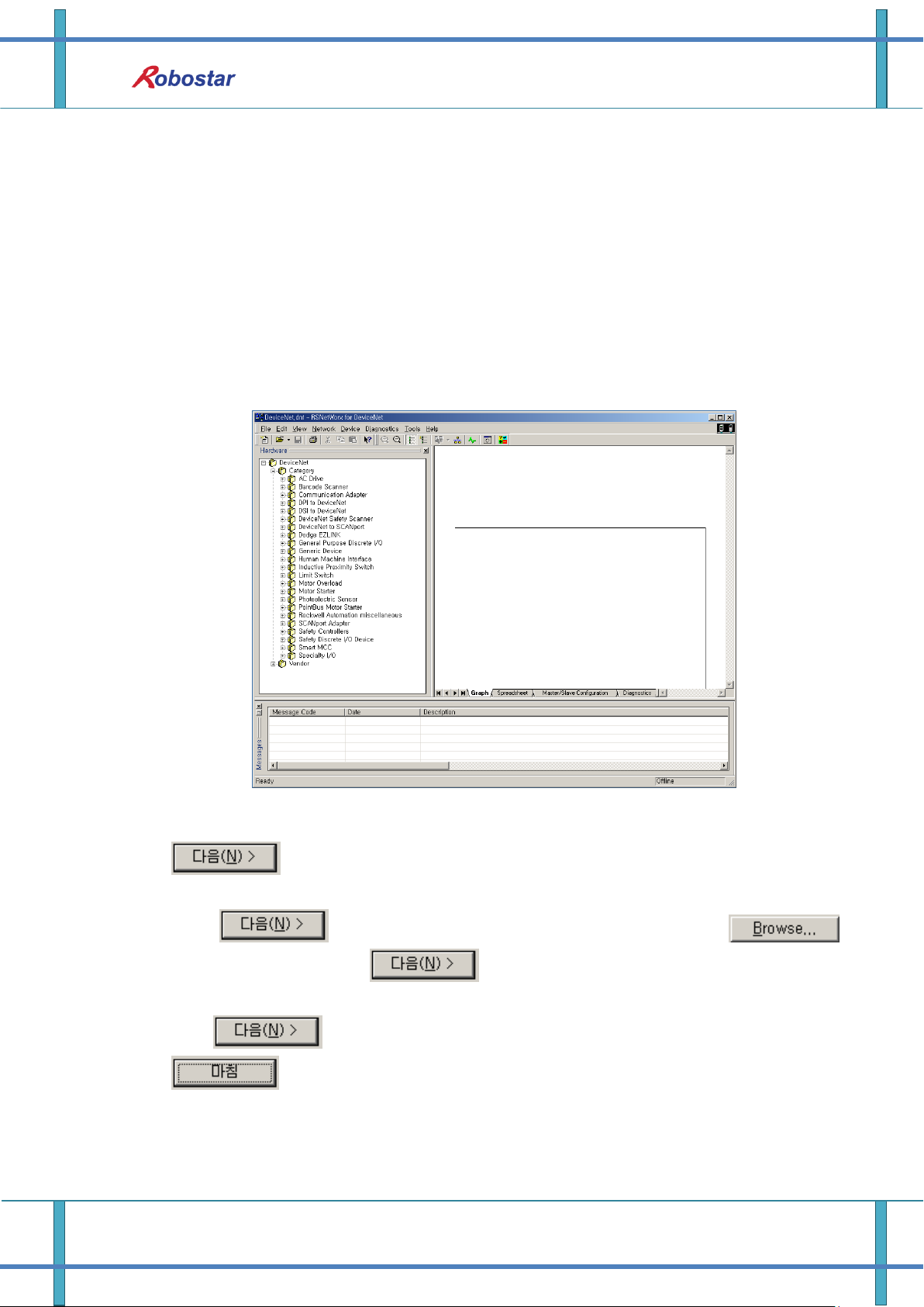
1) Set the N1 node address.
2) Confirm the connection to DeviceNet network before running RsNetworx. With RsNetwor
running, a screen opens up as shown below.
[Fig. 5.1 RSNetwork In-progress Screen]
3) Click Tools -> EDS Wizard on the menu, the EDS Wizard screen comes up. Then, click
icon at the screen. When the Option screen comes up, a Register an EDS File
is checked as default.
4) Click once again, a Registration screen comes up. Click the
icon, find N1.EDS and click , then the EDS File Installation Test Results window
appears.
5) Click three times in a row when no error is found in this window, click
lastly, then the EDS file Install is complete. Once the EDS file has been
normally installed, you can check a directory Robostar has been created at lower end of the
Vendor directory at the Hardware window on the left in Fig. 5.2, with N1 generated in its sub
directory.
5-1 Robostar Co., Ltd
Examples of DeviceNet Setting
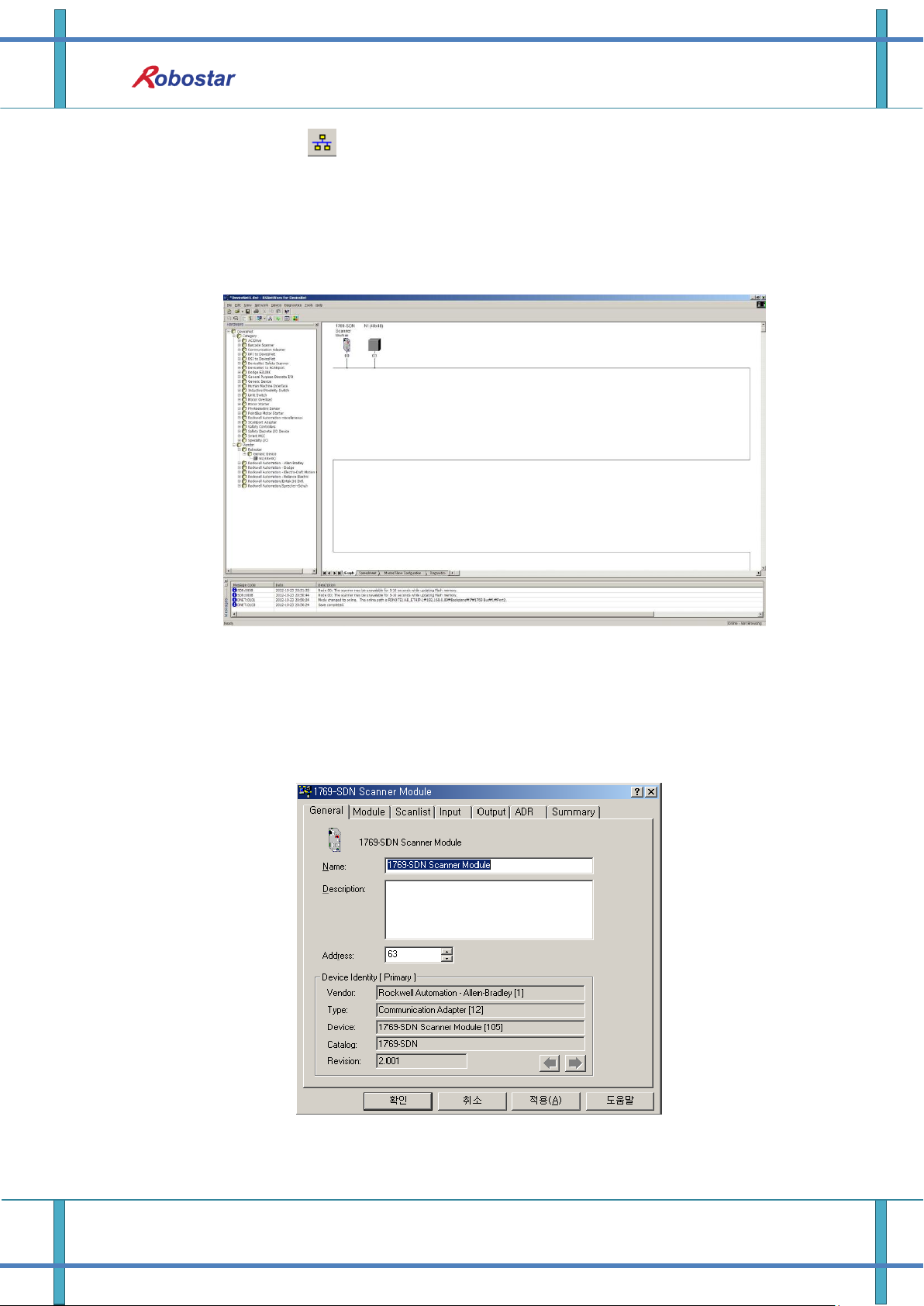
6) In Fig. 5.2, click (Online) icon and a window comes up. Click Check button and
RsNetworx automatically begins to scan Network to find out DeviceNet modules, and a
window showing the results of the scanning, as shown below, according to NODE numbers
set to N1. (The set value for SW3 in Fig. 5.2 is 0(48x48). The node values of the two examples
are set to 3.)
[Fig. 5.2 Screen I/O Allocation 48x48 after Auto Scan]
7) Double-click the 1796-SDN Scanner module and the Fig. 5.4 screen comes up. Click the
Module tab and select CompactLogix used as the example when asked to pick a 1769-SDN
Platform.
[Fig. 5.4 Scanner Setup Screen]
5-2 Robostar Co., Ltd
Examples of DeviceNet Setting
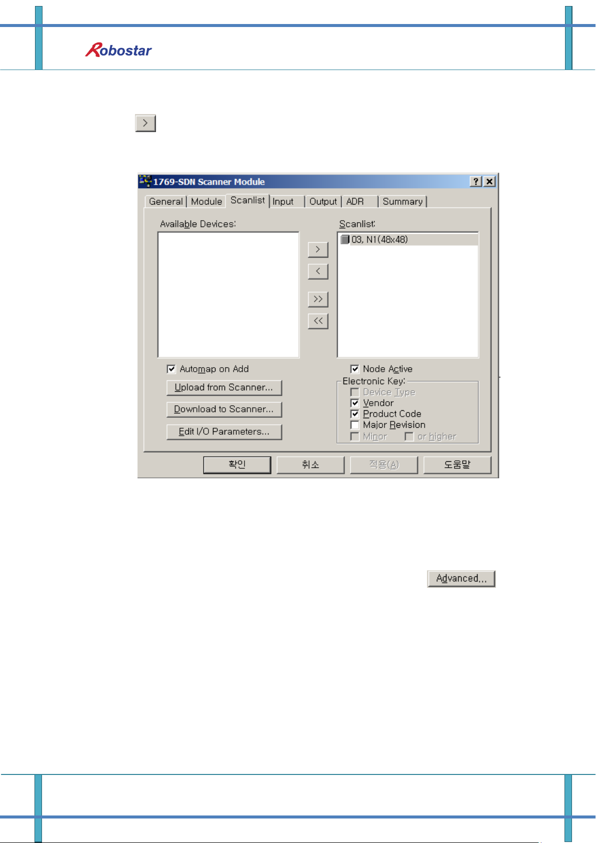
8) Click the Scanlist tab and the Fig. 5.5 screen pops up. Select the N1 in Available Devices and
click , and N1 moves to Scanlist. Click the Download to Scanner on the bottom left and
N1 is registered in the 1769-SDN Scanlist.
[Fig. 5.5 Scanlist Setup Screen]
9) Click the Input tab and you can check the tag numbers in which Input data of N1 is
allocated as shown below. Click the Output tab and you can check the allocated tag numbers
as done in Input data. To modify the tag number manually, click the icon.
5-3 Robostar Co., Ltd
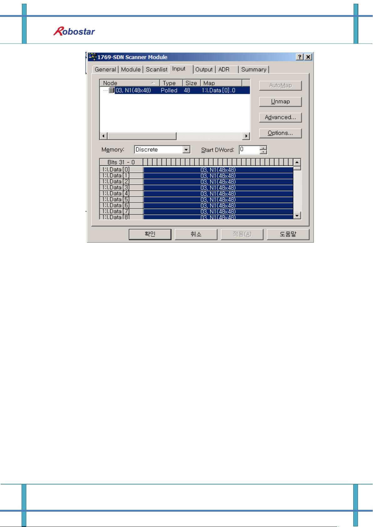
Examples of DeviceNet Setting
[Fig. 5.6 Screen for setting Input data area]
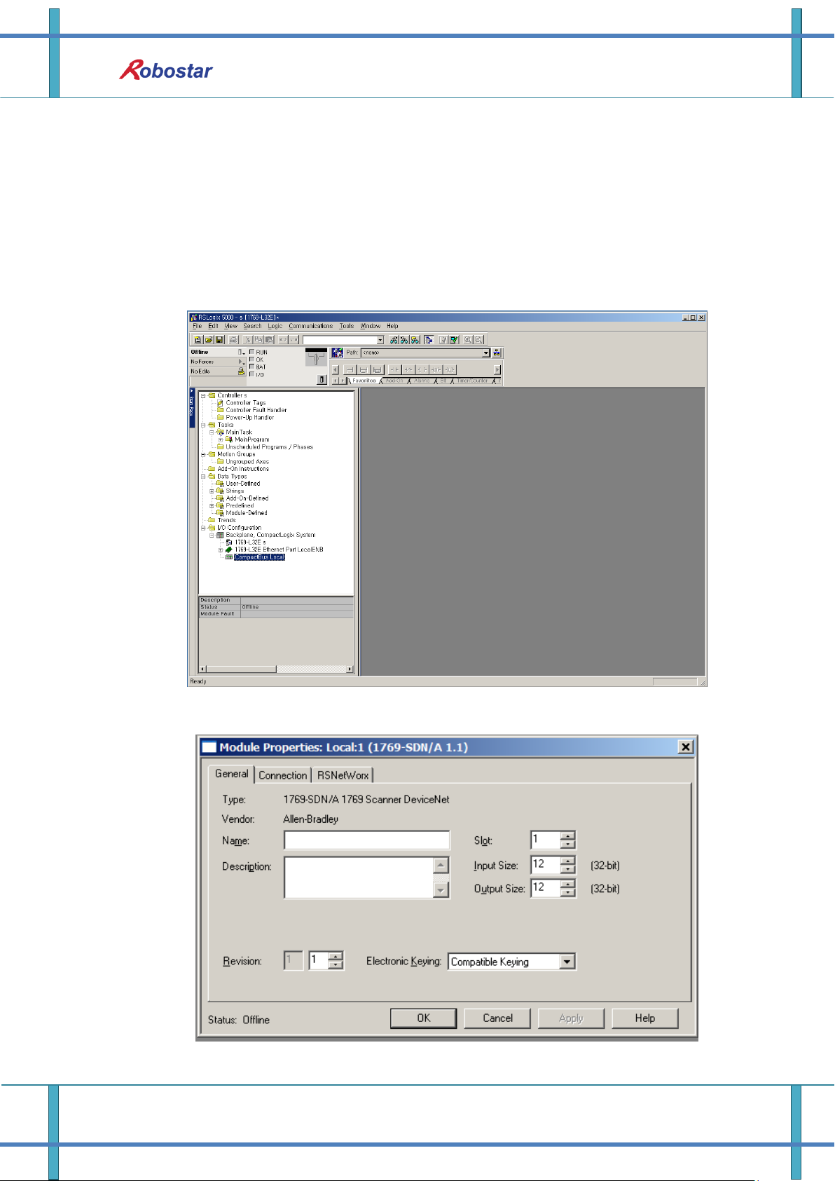
10) Run Rslogix 5000, select File -> New to create a new project. Once a new project has been
created, a screen comes up as shown in Fig. 5.7, in which when you right-mouse click a New
module from CompactBus Local on the bottom left of the screen, a Select module window
comes up. Click the Communications tab and 1769-SDN Scanner pops up. When clicking and
selecting it, you can see 1769-SDN has been created below CompactBus Local tab and Fig.
5.8 screen comes up.
5-4 Robostar Co., Ltd
Examples of DeviceNet Setting
11) In Fig. 5.8, write a name for module management in the ‘name’ section, putting in the I/O
size to use in Devicenet Network when asked about Input size and Output size. In the
example program, Input size is set to 12(46byte) and Output size to 10(40byte) as one N1
module is connected. For reference purpose, Input size and Output size should be set
identically to I/O size set to Scanlist in RSNetworx. Click the Confirm button and RSNetworx
tab to configure the path of the RSNetworx file set and saved in Ch.5 “6)”.
Fig. 5.7 In-progress RsLogix 5000 Screen
Fig. 5.8 1769-SDN Setup Screen
5-5 Robostar Co., Ltd

Examples of DeviceNet Setting
12) Click the Controller Tags on top left in Fig. 5.7 and a screen in Fig. 5-9 comes up, enabling
you to check that the I/O tag values set in Fig. 5.6 found matching and were displayed on
the screen accordingly.
Fig. 5.9 DeviceNet I/O tag screen
13) In the OMROM PLC, I/O data is connected for a real-time exchange upon registering
DeviceNet modules on the Scanlist using Configuration tool. But, the AB PLC allows you to
exchange I/O data only by enabling CommandRegister.Run bit in Fig. 5.10 though registered
on Scanlist.
Fig. 5.10 I/O Run Program
5-6 Robostar Co., Ltd

Controller Data Mapping
DeviceNet Data
Description
DeviceNet Data
Description
INPUT0
System Input #1
OUTPUT0
System Output #1
INPUT1
User Input
OUTPUT1
User Output
INPUT2
Option Input 0
OUTPUT2
Option Output 0
INPUT3
System Input #2
OUTPUT3
Error Code Read
INPUT3
FieldBus Input #1
INPUT4
Option Input 1
OUTPUT4
Option Output 1
INPUT5
Option Input 2
OUTPUT5
Option Output 2
INPUT6
Option Input 3
OUTPUT6
Option Output 3
INPUT7
FieldBus Input #2
OUTPUT7
FieldBus Output #2
INPUT8
1-axis Position Value Input
OUTPUT8
Current 1-axis Position Value Output
INPUT9
OUTPUT9
INPUT10
2-axis Position Value Input
OUTPUT10
Current 2-axis Position Value Output
INPUT11
OUTPUT11
INPUT12
3-axis Position Value Input
OUTPUT12
Current 3-axis Position Value Output
INPUT13
OUTPUT13
INPUT14
4-axis Position Value Input
OUTPUT14
Current 4-axis Position Value Output
INPUT15
OUTPUT15
INPUT16
Global Integer Input
OUTPUT16
Global Integer Output
INPUT17
Global Integer Index
OUTPUT17
Global Float Output
INPUT18
JOG VEL Rate Input
OUTPUT18
INPUT19
Global Point Index
OUTPUT19
Info Data 1 Output
INPUT20
Pull Up Value Input
OUTPUT20
Info Data 2 Output
INPUT21
Global Float Input
OUTPUT21
Info Data 3 Output
INPUT22
OUTPUT22
Info Data 4 Output
INPUT23
Global Float Index
OUTPUT23
Program Num Output
Chapter 6. Memory Mapping
6.1 N1 Controller Data Mapping
Memory Mapping
Note) When using Option I/O, change Parameter I/0 EXT B/D value to 2. (Operation Manual”
1.3.1.3 Extension I/O Board Setting”.)
Note) JOG Velocity Rate Input of RWw10 applies when in JOG Mode, with a setting range from
1 to 100%. The value set is converted by percent per axis based on the Jv values of JOINT
6-1 Robostar Co., Ltd

Memory Mapping
System Input #1
0
CH SEL
8
MODE 1 / AXIS 1
1
PROG 0
9
MODE SEL
2
PROG 1
A
JOG VEL
3
PROG 2
B
VEL+ / MOV+
4
PROG 3
C
VEL- / MOV-
5
PROG 4
D
REBOOT
6
PROG SEL
E
ORG #1
7
MODE 0 / AXIS 0
F
START #1
For description of functions of each Bit, refer to Operation Manual “3.3.4 System
Input/Output Functions”.
MOTION parameters.
6.1.1 N1 Series System Input #1
N1 series has System Bits commonly used between Robot Channel 1 and 2, and these bits operate
differently between channels depending on CH_SEL Bit setting. If CH_SEL Bit set value is Low, it
corresponds to Robot Channel 1, High to Robot Channel 2.
Commonly-used bits are PROG_0 ~ PROG_4, PROG_SEL, MODE0/AXIS0, MODE1/AXIS1, MODE SEL,
JOG VEL, VEL+/MOV+, VEL-/MOV- . Check the CH SEL Bit set value when using the commonly-used
bits. When the CH SEL Bit set value is not correct, an unwanted robot channel may operation. The
FieldBus timing diagram marked in this Manual is examples for Channel 1, and for handling and
operating Channel 2 change CH_SEL Bit set value in Channel 1 timing diagram to High. Reading and
writing Global Integer and Global Float Data CH_SEL Bit can be used regardless of setting.
6-2 Robostar Co., Ltd

Memory Mapping
System Input #2
FieldBus Input #1
0
STOP #1
8
DATA TYPE: XY Coordinates
1
Reserved
9
DATA TYPE: Angle Coordinates
2
SERVO ON #1
A
Data Type: Pulse (Read Only)
3
ORG #2
B
Mode Select (/Current OR GPNT)
4
START #2
C
Write Enable Flag(Position,GINT)
5
STOP #2
D
READ Enable Flag(Position, GINT)
6
Reserved
E
Reserved
7
SERVO ON #2
F
Reserved
FieldBus Input #2
0
JOG A(X)+
8
AUTO RUN MODE
1
JOG A(X)-
9
STEP RUN MODE
2
JOG B(Y)+
A
JOG MODE
3
JOG B(Y)-
B
JOG Forward SEL
4
JOG Z+
C
Reserved
5
JOG Z-
D
Reserved
6
JOG W+
E
Info Data Mode SEL #0
7
JOG W-
F
Info Data Mode SEL #1
System Output #1
0
CH SEL
8
ORG OK #2
1
ALL ALARM
9
RUNNING #2
2
READY #1
A
INPOS/INRNG #2
3
ORG OK #1
B
SERVO ON #2
4
RUNNING #1
C
Reserved
5
INPOS/INRNG #1
D
Reserved
6
SERVO ON #1
E
Reserved
7
READY #2
F
Reserved
6.1.2 N1 Series System Input #2 & FIELDBUS INPUT#1
6.1.3 N1 Series FIELDBUS INPUT #2
6.1.4 N1 Series System Output #1
6-3 Robostar Co., Ltd

FieldBus Output #2
0
Write Complete Flag
8
Auto Run Mode DIS
1
Read Complete Flag
9
Step Run Mode DIS
2
Reserved
A
JOG Mode DIS
3
Forward Moving State DIS
B
Reserved
4
Reserved
C
TRQ Info Data Mode
5
Brake State DIS
D
RPM Info Data Mode
6
Reserved
E
Reserved
7
Reserved
F
Reserved
Times displayed in Field Bus timing diagram are as follow.
T1: 20ms, T2: 30ms, T3: 40ms.
The pulse width entered when applying Field Bus should be kept over a minimum of 20ms.
The time interval between signals entered when applying Field Bus should be over at least
20ms.
6.1.5 N1 Series FIELDBUS Output #2
6.2 Precautions for Use in N1 Series System Mode
Memory Mapping
1. < Precaution for Use in Auto Mode >
① As GINT, GFLOAT and GPNT commonly use Read / Write Enable Flag, the index
values of unused variables are allocated at a time when no change is desired.
② Of Data types, XYZW and ABZW are only Coordinate Write functions available for
use.
③ PROGRAM NUM output generates only the PROGRAM NUM entered in SYSTEM
MODE.
④ VEL output is capable of generating robot’s moving speed in JOG MODE and AUTO
MODE.
2. < Precautions for use in JOG Mode >
① JOG_VEL input is available for use only in JOG MODE and when the value is 0 it runs
at 1% speed.
② VEL output is capable of generating robot’s moving speed in JOG MODE and AUTO
MODE.
③ Pulse inputs should be made to enter AUTO RUN MODE, STEP RUN MODE and JOG
MODE in Field Bus Input #2. (When each mode is set to High, the selected bit on
Jog axis in FieldBus Input #2 is operated under abnormal conditions.)
6-4 Robostar Co., Ltd

PLC(PC)
-> N1 Series
N1 Series
-> PLC(PC)
Brake State DIS
H
L
PROG: 2
PROGRAM NUM
RUNNING #1
HLH
L
READY #1
AUTO RUN MODE
DIS
ORG OK #1
HLHLH
L
L
SERVO ON #1
H
L
ORG #1
H
L
PROG SEL
H
CH SEL
H
L
AUTO RUN MODE
H
L
START #1
L
PROG 0:4
H
H
PROG: 2
CH DIS
H
L
L
T1
T3
Memory Mapping
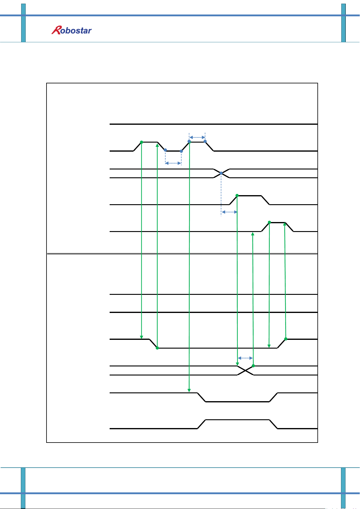
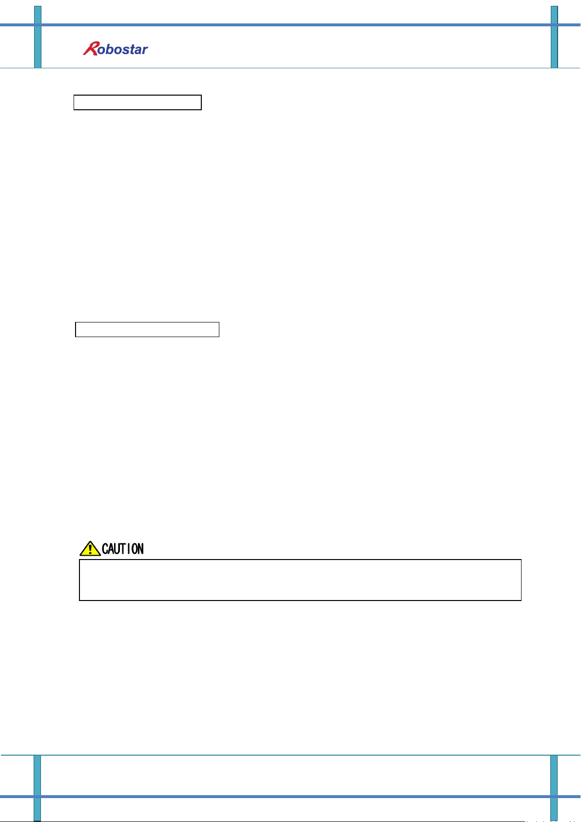
6.3 N1 Series FieldBus(CC_Link) Timing Diagram
.
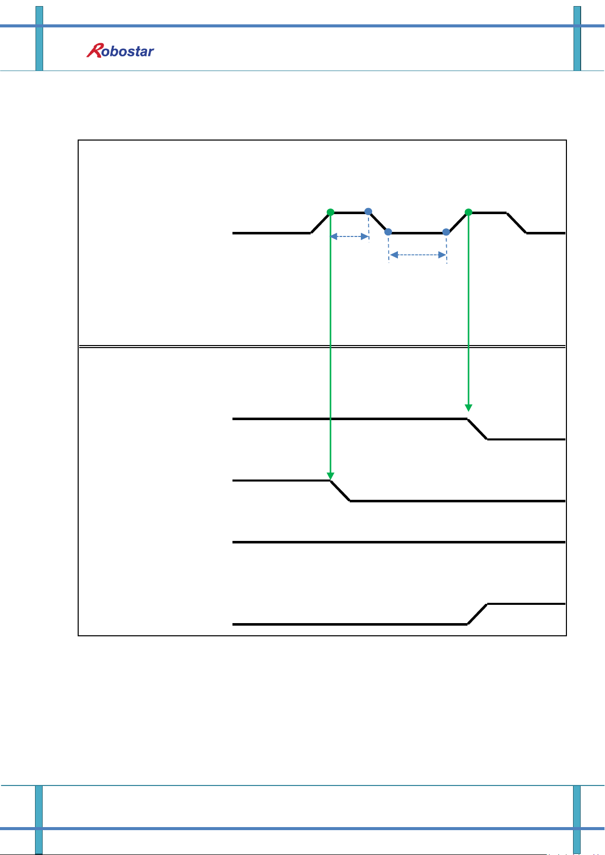
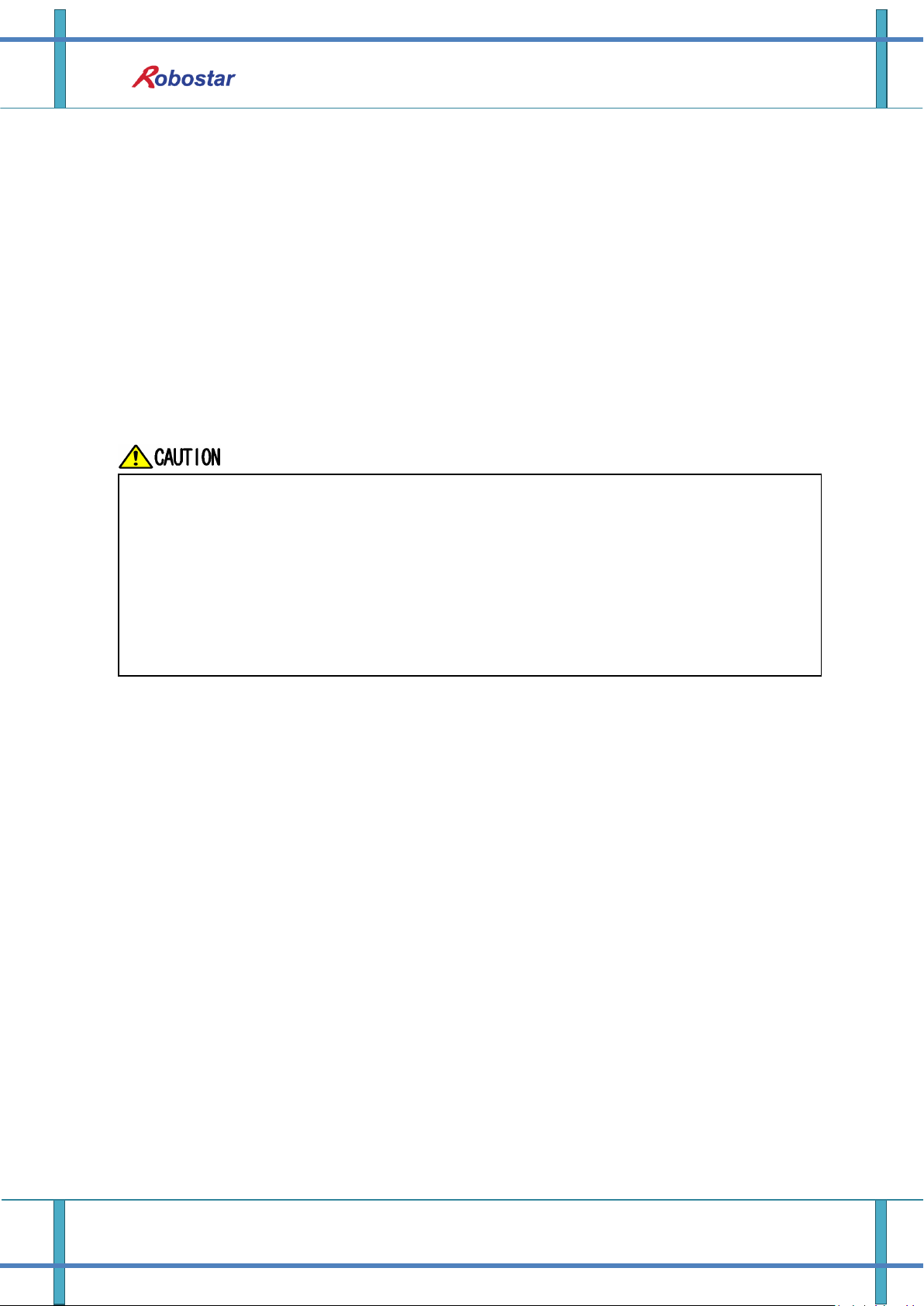
6.3.1 Operation in AUTO RUN MODE
6-5 Robostar Co., Ltd
Memory Mapping
Check AUTO SERVO ON for setting in Parameter of N1 Series. (Refer to Operation
Manual “1.3.1.5 Auto Servo On”.)
When Auto Servo ON is not set, output SERVO ON #1 Bit as High prior to
sending out START #1 Signal.
When in Auto Servo ON
When not in Auto Servo ON
Description :
Set CH SEL Bit. (Low: Channel 1, High: Channel 2)
Enter AUTO RUN MODE Bit into pulse format. (High status should be kept over 20ms.)
When ORG OK#1 Signal is Low in N1 Series, set ORG #1 Bit to High.
When ORG OK #1 is changed to High, combine PROG 0~4 Bits to set the desired JOB
Program num. (PROG0 Bit is the lowest (LSB) Bit and PROG4 Bit is the highest (MSB) Bit.)
With completion of setting JOB Program num, set PROG SEL Bit to High.
Check PROGRAM NUM sent from N1 Controller and set START #1 Bit to High.
Description :
Set CH SEL Bit. (Low: Channel 1, High: Channel 2)
Set AUTO RUN MODE Bit into pulse format. (High status should be kept over 20ms.)
When ORG OK#1 Signal is not set to High in N1 Series, set ORG #1 Bit to High.
When ORG OK #1 is changed to High, combine PROG 0~4 Bits to set the desired JOB
Program num. (PROG0 Bit is the lowest (LSB) Bit and PROG4 Bit is the highest (MSB) Bit.)
With completion of setting JOB Program num, set PROG SEL Bit to High.
Enter SERVO ON#1 Bit in Pulse format. Check SERVO ON#1 of System Output #1 in N1
Series to see if SERVO is ON. (High status should be kept over 20ms.)
Check PROGRAM NUM sent from N1 Controller and set START #1 Bit to High.
6-6 Robostar Co., Ltd
PLC(PC)
-> N1 Series
N1 Series
-> PLC(PC)
Brake State DIS
H
L
CH SEL
H
L
CH DIS
H
PROG: 2
PROGRAM NUM
SERVO ON #1
H
LHL
H
STOP #1
PROG 0:4
PROG SEL
START #1
ORG #1
RUNNING#1
LHLHLHL
LHL
PROG:3
H
L
PROG:3
PROG: 2
T3
T1
T1
Note 1
Note 2
Note 3
T1
Memory Mapping
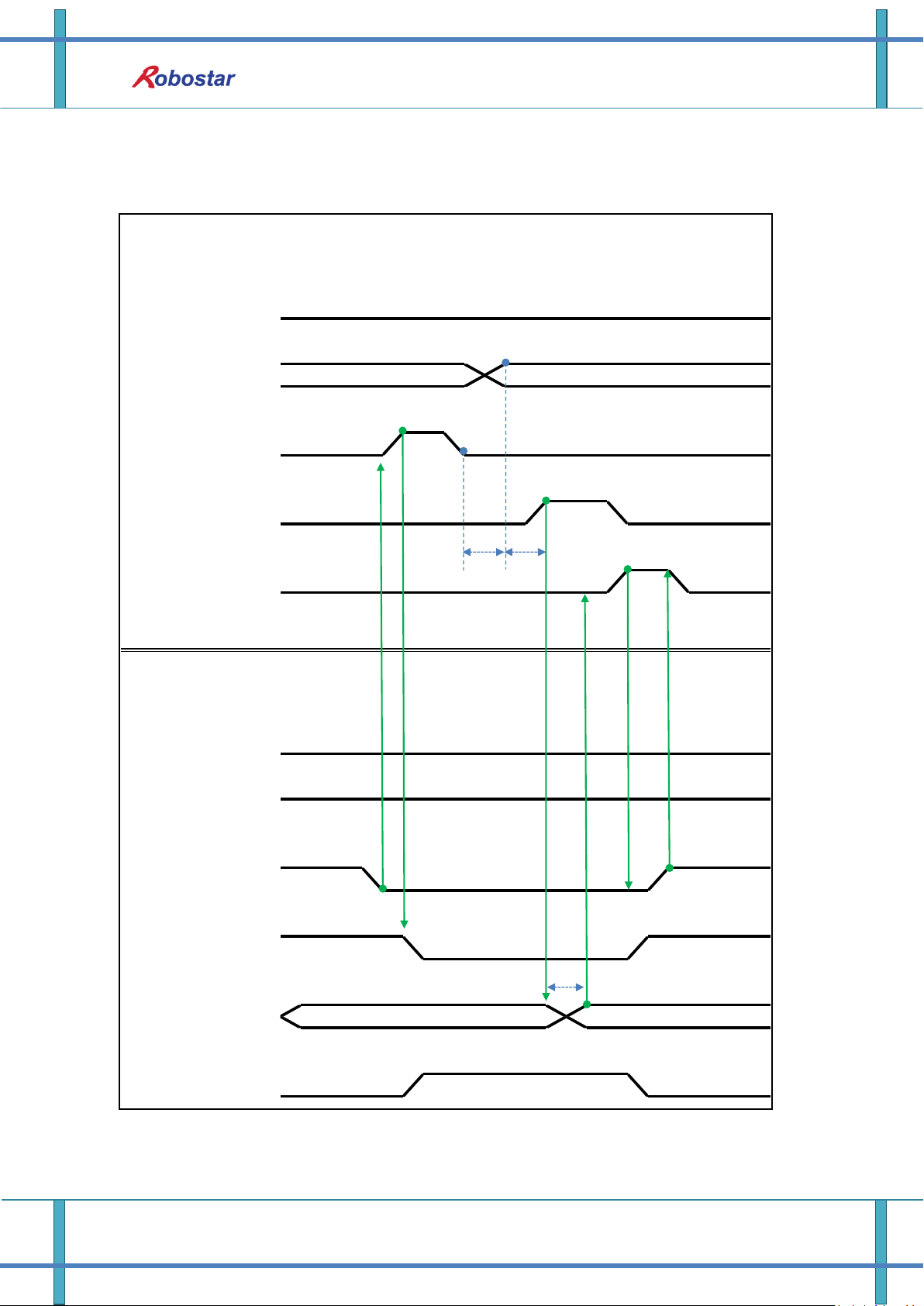
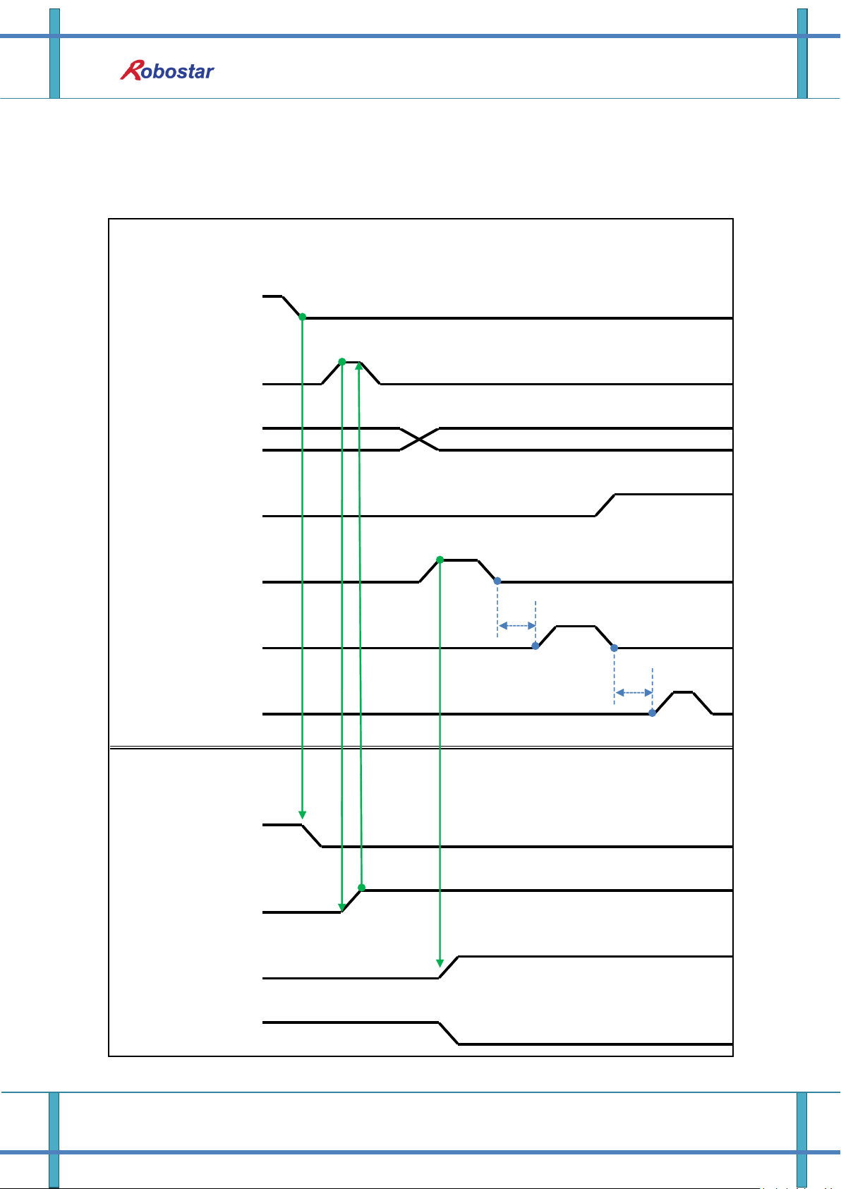
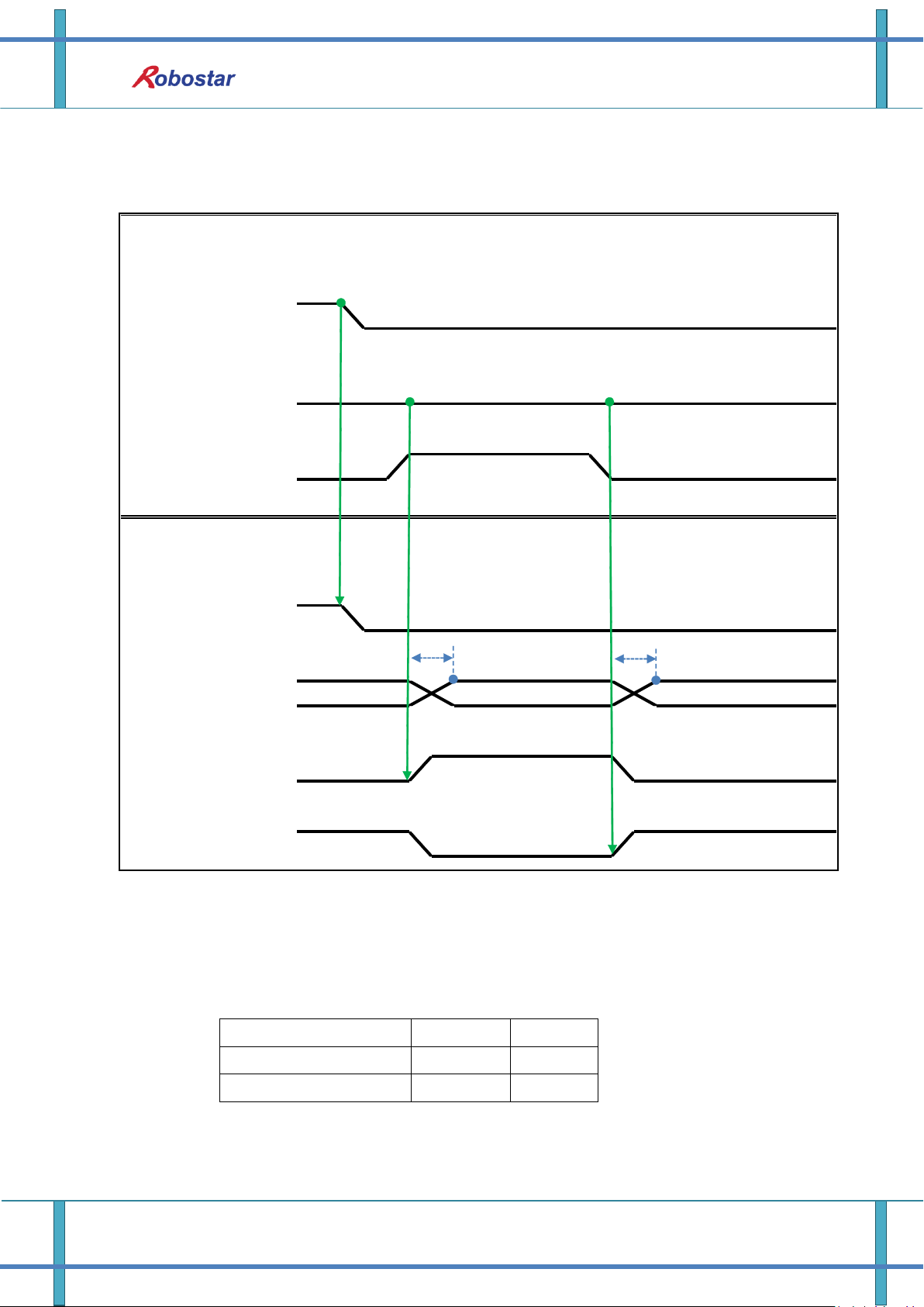
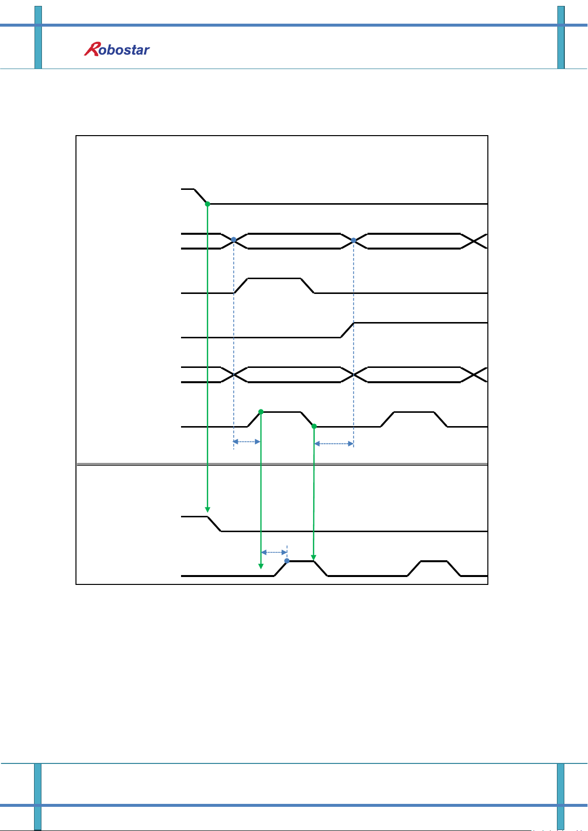
6.3.2 JOB Program Change during JOB Operation
6-7 Robostar Co., Ltd
Memory Mapping
Changing JOB Program can only be made with Servo OFF. Prior to changing JOB
Program, check the Servo OFF status.
When in Auto Servo ON
When not in Auto Servo ON
Description :
Enter STOP #1 Signal into pulse. (High status should be kept over 20ms.)
Combine PROG 0~4 Bits to enter the desired JOB Program num. (PROG0 Bit is the lowest
(LSB) Bit and PROG4 Bit is the highest (MSB) Bit.)
With completion of setting JOB Program num, set PROG SEL Bit to High.
Check PROGRAM NUM sent from N1 Controller and set START #1 to High.
Note 1) Signal for stopping JOB Program from operating while running JOB Program.
Note 2) Signal for changing SERVO OFF status and initializing JOB Program.
Note 3) Robot Moving speed may lead to a difference in time taken for change to Low.
(Maximum delay time lasts as At time as set in Joint/Linear Motion Parameter.)
Description :
Enter STOP #1 Signal into pulse. (High status should be kept over 20ms.)
Instead of entering the 2
nd
STOP #1 Signal, enter SERVO ON #1 Signal in Pulse. (High status
should be kept over 20ms.)
Combine PROG 0~4 Bits to enter the desired JOB Program num. (PROG0 Bit is the lowest
(LSB) Bit and PROG4 Bit is the highest (MSB) Bit.)
With completion of setting JOB Program num, set PROG SEL Bit to High.
Check PROGRAM NUM sent from N1 Controller and enter SERVO ON #1 Signal in Pulse.
(High status should be kept over 20ms.)
Set START #1 to High.
6-8 Robostar Co., Ltd
PLC(PC)
-> N1 Series
N1 Series
-> PLC(PC)
LHLHL
Brake State DIS
HLHLH
PROG:3
PROG: 2
PROG:3
PROG: 2
PROG 0:4
PROG SEL
START #1
ORG #1
RUNNING#1
PROGRAM NUM
H
L
CH SEL
H
L
CH DIS
H
L
STOP#1
H
H
L
L
SERVO ON#1
H
L
T1
T3
Note 1
T1
Memory Mapping
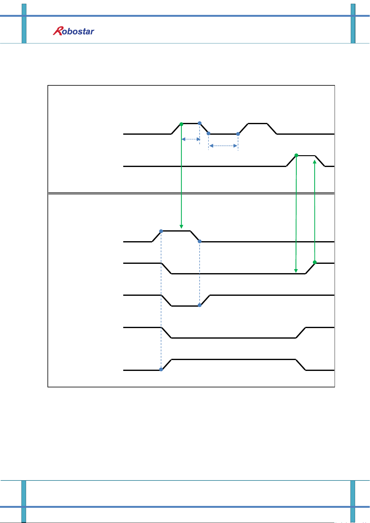
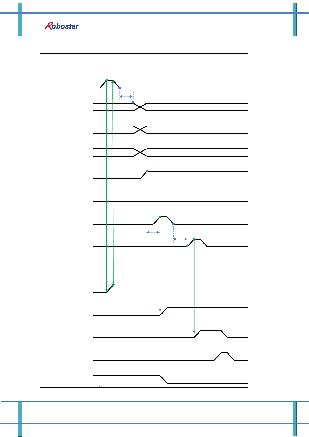
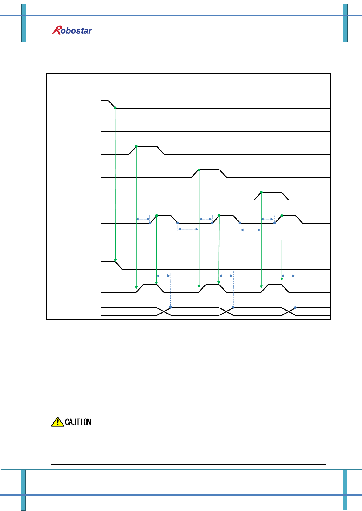
6.3.3 JOB Program Change after Completing JOB Program
6-9 Robostar Co., Ltd

Memory Mapping
When in Auto Servo ON
When not in Auto Servo ON
Description :
Check if RUNNING#1 Bit is Low.
Enter STOP #1 Signal into pulse. (High status should be kept over 20ms.)
Combine PROG 0~4 Bits to enter the desired JOB Program num. (PROG0 Bit is the lowest
(LSB) Bit and PROG4 Bit is the highest (MSB) Bit.)
With completion of setting JOB Program num, set PROG SEL Bit to High.
Check PROGRAM NUM sent from N1 Controller and set START #1 to High.
Note 1) When JOB ends in JOB Program by EOP, RUNNING#1 Bit is changed into Low.
Description :
Instead of STOP #1 Signal, enter SERVO ON#1 Signal into pulse. (High status should be kept
over 20ms.)
Combine PROG 0~4 Bits to enter the desired JOB Program num. (PROG0 Bit is the lowest
(LSB) Bit and PROG4 Bit is the highest (MSB) Bit.)
With completion of setting JOB Program num, set PROG SEL Bit to High.
Check PROGRAM NUM sent from N1 Controller and enter SERVO ON #1 Signal into pulse.
(High status should be kept over 20ms.)
Set START #1 to High.
6-10 Robostar Co., Ltd
Memory Mapping
PLC(PC)
-> N1 Series
N1 Series
-> PLC(PC)
HLH
LHLHLHLHL
SERVO ON #1
STOP #1
START
ALL ALARM
RUNNING#1
READY #1
L
Brake State DIS
H
T1
Note 1
Note 2
T1
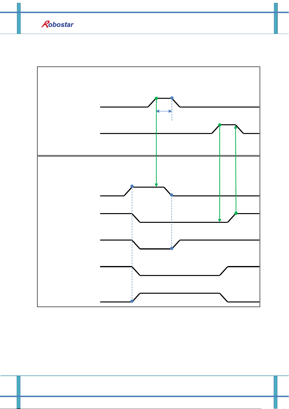
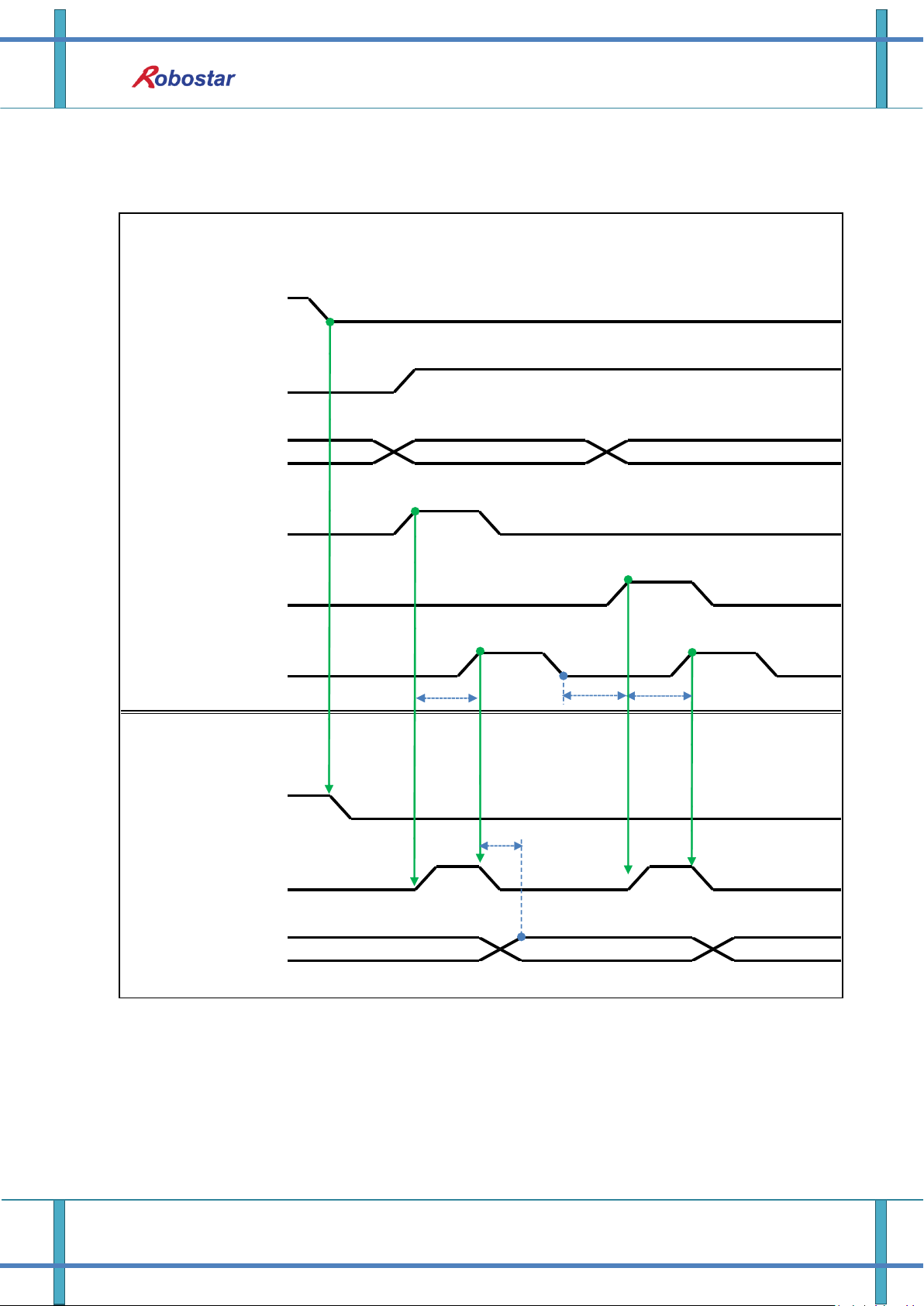
6.3.4 JOB Program START after Disabling Alarm
6-11 Robostar Co., Ltd

When in Auto Servo ON
When not in Auto Servo ON
Description :
Enter STOP #1 Signal into pulse twice. (High status should be kept over 20ms.)
Set START #1 to High.
Note 1) Signal for disabling an alarm.
Note 2) Set JOB Program STEP Line for the first time.
Description :
Enter STOP #1 Signal into pulse twice. (High status should be kept over 20ms.)
Set START #1 to High.
Memory Mapping
6-12 Robostar Co., Ltd
Memory Mapping
PLC(PC)
-> N1 Series
N1 Series
-> PLC(PC)
L
Brake State DIS
H
SERVO ON #1
STOP #1
START
ALL ALARM
RUNNING#1
READY #1
HLHLHLHLH
LHL
T1
6.3.5 JOB Program Restart after Disabling Alarm
6-13 Robostar Co., Ltd

When in Auto Servo ON
When not in Auto Servo ON
Description :
Enter STOP #1 Signal into pulse. (High status should be kept over 20ms.)
Set START #1 to High.
Description :
Enter STOP #1 Signal into pulse. (High status should be kept over 20ms.)
Enter SERVO ON #1 Signal into pulse. (High status should be kept over 20ms.)
After checking SERVO ON, set START #1 to High.
Memory Mapping
6-14 Robostar Co., Ltd
Memory Mapping
PLC(PC)
-> N1 Series
N1 Series
-> PLC(PC)
STOP #1
SERVO ON #1
HHH
L
L
L
Brake State DIS
HLH
READY #1
RUNNING#1
L
Note 1
Note 2
T1
T1
6.3.6 SERVO OFF
6-15 Robostar Co., Ltd

When not in Auto Servo ON, Servo OFF does not apply though the 2
nd
STOP #1
Signal is sent out.
To keep Servo OFF, send SERVO ON #1 Signal via Pulse.
When in Auto Servo ON
When not in Auto Servo ON
Description :
Enter STOP #1 Signal into pulse. (High status should be kept over 20ms.)
Note 1) Signal for stopping JOB Program from operating.
Note 2) Signal for turning SERVO OFF.
Description :
Enter STOP #1 Signal into pulse. (High status should be kept over 20ms.)
Instead of the 2
nd
STOP #1 Signal \, enter SERVO ON #1 Signal into pulse.
(High status should be kept over 20ms.)
Memory Mapping
6-16 Robostar Co., Ltd

PLC(PC)
-> N1 Series
N1 Series
-> PLC(PC)
HLHLHLHLHLHLHLHLH
L
REBOOT
PROG 0:4
PROG SEL
START #1
RUNNING#1
PROG: 3
PROG:3
READY #1
ALL ALARM
PROGRAM NUM
PROG:3
PROG: 3
SERVO ON #1
T1
R
E
B
O
O
T
I
N
G
more than 100ms
Note 1
T3
Memory Mapping
6.3.7 Rebooting
Description :
Set REBOOT Bit to High. Rebooting becomes available only when High status is kept over
100ms. When kept below 100ms, Rebooting may not be performed.
When Rebooting is complete yet alarm conditions are not disabled, ALARM Bit maintains
High status. In this case, disable all alarm conditions and retry Rebooting.
6-17 Robostar Co., Ltd

Memory Mapping
Note 1) When Rebooting, Signals may malfunction so use caution.
A timing diagram upon completion of Rebooting is identical to “6.3.2 AUTO RUN.
When Rebooting is complete, READY #1 Signal turns into High, when JOB Program num is
set.
Check PROGRAM NUM sent from N1 Controller and set START #1 Bit to High.
6-18 Robostar Co., Ltd

PLC(PC)
-> N1 Series
N1 Series
-> PLC(PC)
L
HHHLH
L
JOG MODE DIS
CH SEL
STEP RUN MODE DIS
AUTO RUN MODE
DIS
H
LHL
L
CH SEL
JOG MODE
STEP RUN MODE
AUTO RUN MODE
HLH
L
Memory Mapping
6.3.8 MODE(AUTO, STEP, JOG) Change
6-19 Robostar Co., Ltd

Description :
MODE can be converted only with SERVO OFF.
Check CH SEL Bit before changing MODE.
When CH SEL Bit is wrongly set, another Channel MODE changes.
Use CH SEL Bit to select the desired Channel. (Low: Channel 1, High: Channel 2)
Select the desired operation MODE(AUTO RUN, STEP RUN, JOG).
Enter MODE Signal in Pulse format when High status should be kept over 20ms.
Memory Mapping
6-20 Robostar Co., Ltd

Memory Mapping
PLC(PC)
-> N1 Series
N1 Series
-> PLC(PC)
VEL-/MOV-
H
L
READY #1
H
SERVO ON#1
H
L
CH DIS
H
PROG 0~4
H
L
L
CH SEL
H
L
RUNNING
STEP MODE
PROG 0~4
PROG_SEL
START
VEL+/MOV+
STEP MODE DIS
HLHLHLHLHLHLH
L
PROG 0:4
L
PROG 0:4
T1
T1
T1
Running ROBOT
T1
T3
T1
Note 1
Note 2
Note 3
Note 4
Note 5
Note 6
When in Auto Servo ON
6.3.9 STEP MODE
Description:
Enter STEP MODE Bit in System Input #2 into pulse. (High status should be kept over 20ms.)
Once STEP MODE has been set, STEP MODE DIS is set to High.
Combine PROG 0~4 Bits to set the desired JOB Program num. (PROG0 Bit is the lowest (LSB)
Bit and PROG4 Bit is the highest (MSB) Bit.)
Once JOB Program num setting is complete, set PROG SEL Bit to High.
Check PROGRAM NUM sent from N1 Controller.
Use START Bit in System Input #1 to run JOB.
Use VEL+/ VEL- Bit in System Input #1 to select the desired JOB step.
Select the desired STEP to operate, enter START#1 Bit into pulse.
6-21 Robostar Co., Ltd

Memory Mapping
When not in Auto Servo ON
Use START Bit and run it with one STEP increase at a time.
To view the only desired motion, use VEL+/VEL- Bit, set to the desired motion STEP Line, use
START #1 Bit for operation.
Note 1) Means JOB Program START. (Currently Step Line: 1)
Note 2) Add +1 to JOB program Step. (Currently Step Line: 2)
Note 3) Run the current Step Line. Add +1 to Step. (Step Line: 3)
Note 4) Subtract -1 from the current Step. (Step Line: 2)
Note 5) Subtract -1 from the current Step. (Step Line: 1)
Note 6) Run the current Step Line. Add +1 to Step. (Step Line: 2)
Description :
Enter STEP MODE Bit in System Input #2 into pulse. (High status should be kept over 20ms.)
Once STEP MODE has been set, STEP MODE DIS is changed to High.
Combine PROG 0~4 Bits to set the desired JOB Program num. (PROG0 Bit is the lowest
(LSB) Bit and PROG4 Bit is the highest (MSB) Bit.)
Once JOB Program num is complete, change PROG SEL Bit to High.
Check PROGRAM NUM sent from N1 Controller.
Enter SERVO ON#1 Bit into pulse. Check SERVO ON#1 in System output # on N1 Series to
see if it is in SERVO ON.
Use START Bit in System Input #1 to operate JOB.
Use VEL+/ VEL- Bit in System Input #1 to select the desired JOB step.
Select the desired STEP to operate and enter START#1 Bit into Pulse.
Use START Bit and run it with one STEP increase at a time.
6-22 Robostar Co., Ltd
PLC(PC)
-> N1 Series
N1 Series
-> PLC(PC)
SERVO ON #1
H
L
L
CH SEL
H
L
H
HLH
L
H
JOG VEL : 10
JOG VEL : 20
HLHLH
L
JOG MODE
JOG VEL
JOG A(X) +
JOG Z +
SERVO ON #1
CH DIS
H
Brake State_DIS
L
JOG MODE DIS
JOG VEL RATE
LHL
T1
T1
Memory Mapping
6.3.10 Operation in JOG MODE
6-23 Robostar Co., Ltd
Memory Mapping
When Velocity Rate Input is 0, operation is performed at 1% speed.
In JOG MODE SET BIT, enter PULSE.
When operating JOG, Auto Servo ON does not apply regardless of setting Auto
Servo ON.
When operating JOG, be sure to send out SERVO ON #1 Signal to turn into Servo
ON.
When not selecting a coordinate, it operates by Angle coordinate.
Description:
Enter JOG MODE Bit in FIELDBUS INPUT #2 into Pulse.
Once JOG MODE has been set, JOG MODE DIS is set to High.
Use JOG MODE DIS for details about the currently selected MODE, maintaining its state until
AUTO MODE or STEP MODE is selected.
Set the moving speed during JOG operation, with an input range of 0 to 100%.
Setting is done selectively among JOG X(A)+ ~ JOG W- in FIELDBUS INPUT #2.
When setting JOG VEL Bit to Low, operation is performed at speed of the set value for
JOG VEL RATE.
6-24 Robostar Co., Ltd
PLC(PC)
-> N1 Series
N1 Series
-> PLC(PC)
JOG VEL RATE
GPNT INDEX
PULLUP VALUE
H
H
L
LLLHL
H
HLH
HLHLH
JOG MODE
Angle 좌표
H
L
JOG MODE DIS
H
L
L
Velocity Rate Input
GPNT Index
PULL UP VALUE
XY 좌표
H
L
SERVO ON#1
L
H
JOG FWD
SERVO ON #1
FORWARD STATE DIS
INPOS/INRNG #1
Brake state DIS
T1
T1
T1
Memory Mapping
6.3.11 Forward Operation in JOG MODE
6-25 Robostar Co., Ltd
Memory Mapping
When Velocity Rate Input is 0, operation is performed at 1% speed.
In JOG MODE SET BIT, enter PULSE.
When operating JOG, Auto Servo ON does not apply regardless of setting Auto Servo
ON.
When operating JOG, be sure to send out SERVO ON #1 Signal to turn into Servo ON.
When selecting Angle coordinate from Scara Robot Type, JMOV operates and when
selecting XY coordinates operation is performed by LMOV.
Description:
Use JOG MODE DIS state Bit for details about the currently selected MODE, maintaining its
state until selecting AUTO MODE or STEP MODE.
Set the speed to apply when performing JOG FWD operation, with input range of 0 to 100%
and initial value of 1%)
Set the GP Point Index to move.
Set the PULL UP value to apply during FWD operation.
Enter JOG FWD Bit in FIELDBUS INPUT #2 into Pulse.
When running Forward operation, Forward State DIS bit is set to High and turns into Low
with completion of operation.
6-26 Robostar Co., Ltd
Memory Mapping
PLC(PC)
-> N1 Series
N1 Series
-> PLC(PC)
TRQ
RPM
TRQ
HLH
H
LLLHLHL
L
H
TRQ Info Data Mode
H
CH DIS
Info Data Mode SEL
#0
Info Data Mode SEL
#1
CH DIS
Info Data 1:4
RPM Info Data Mode
T3
T3
TRQ
RPM
Info Data Mode SEL #0
LOW
LOW
Info Data Mode SEL #1
LOW
HIGH
6.3.12 Read RPM, TRQ
Description:
Sends out TRQ or RPM value according to Info Data Mode 0:1 setting.
Information about current output values can be confirmed via TRQ Info Data Mode Bit and
RPM Info Data Mode Bit.
6-27 Robostar Co., Ltd
Memory Mapping
PLC(PC)
-> N1 Series
N1 Series
-> PLC(PC)
L
CH DIS
HLH
H
Read Ready &
Complete Flag
Position Value :
Read Enable Flag
LHL
Mode :
/Current , GPNT
Data Type :
XY
Data Type :
Angle
Data Type :
Pulse
H
L
LHLHL
H
CH SEL
H
L
CURRENT POSITION(XY Data)
CURRENT POSITION(Angle Data)
(Pulse Data)
CURRENT POSITION
T1T3T2
T1
T1
T2
T3
T3
If Data Type is not changed to Low in Read Enable Flag High, Read Ready & Complete
Flag instantly turns back into High.
The minimum standby time is required in Current Position Read following change to
Data Type.
6.3.13 Read Current Position
Description:
Sets CH SEL Bit. (Low: Channel 1, High: Channel 2)
Set Data Type(XYZW, ABZW) for reading the Current Position.
To read the current position, set Mode Select bit to Low. (Low: Reads robot’s current
coordinate, High: Reads Global Point)
Enable determining if readable using Read Ready & Complete Flag Bit in System OUT2.
Use Read Enable Flag to be able to read the current position value.
The minimum standby time (T2:30ms) is needed when reading the current position in
accordance with change to Data Type.
6-28 Robostar Co., Ltd
Memory Mapping
PLC(PC)
-> N1 Series
N1 Series
-> PLC(PC)
H
CH DIS
H
Data Type :
XY
H
L
GPNT Index
GPNT Index
Data Type :
Angle
L
Read Enable Flag
H
L
Read Ready &
Complete Flag
Position Value :
CH SEL
H
L
GPNT Index
H
L
Mode :
/Current , GPNT
H
L
LHL
GLOBAL POINT
(Angle Data)
H
L
GLOBAL POINT(XY Data)
T1
T3
T2
T1
6.3.14 Read GLOBAL Point
6-29 Robostar Co., Ltd
Memory Mapping
If Data Type is not changed to Low in Read Enable Flag Signal High, Read Ready
& Complete Flag instantly turns back into High.
The minimum standby time is required in continual Global Point Read.
Description :
Set CH SEL Bit. (Low: Channel 1, High: Channel 2)
Set Mode Select bit to High. (Low: (Low: Reads robot’s current coordinate, High: Reads
Global Point)
Set GPNT Index.
After delaying as much time as T1(20ms), set Read Enable Flag Bit to High, when Read
Ready&Complete Flag state should be High.
Depending on a Data Type choice, the values saved in Global Point can be read by XY
coordinate value or Angle value.
When Read Enable Flag Bit in Field Bus Input #1 is set to High, GLOBAL Point of N1 Series is
set.
When Global Point Read occurs continually, a delay time of T2(30ms) is needed.
6-30 Robostar Co., Ltd
Memory Mapping
PLC(PC)
-> N1 Series
N1 Series
-> PLC(PC)
Position Value(Angle Date)
Position Value(XY Data)
Write Enable Flag
H
L
Position Value :
H
L
GPNT Index
Data Type :
XY
H
L
GPNT Index
H
L
GPNT Index
Write Complete Flag
H
L
CH DIS
H
L
CH SEL
H
L
Data Type :
Angle
H
L
T1
T3
T2
6.3.15 Write GLOBAL Point
6-31 Robostar Co., Ltd

Memory Mapping
Data Type is available only in XY coordinates and Angle coordinate.
GINT, GFLOAT and GPOINT commonly use Read Enable Flag so the Index value of
an unused variable is allocated at a time when no change is desired.
The minimum standby time is required in continual GPOINT Write.
Description:
Set CH SEL Bit. (Low: Channel 1, High: Channel 2)
Set Global Point Index and Data Type(XYZW, ABZW).
Set the position data of each axis to save.
With completion of setting GPNT Index and Data Type, set Write Enable Flag Bit in Field Bus
Input #1 to High.
When the saving process is complete in N1 Series, Write Complete Flag is changed into High.
When Write Enable Flag Bit is set to Low, Write Complete Flag is also changed to Low.
When saving the continual Global Point, a delay time of T2(30ms) is needed.
6-32 Robostar Co., Ltd

Memory Mapping
PLC(PC)
-> N1 Series
N1 Series
-> PLC(PC)
GINT Index 입력
Read Enable Flag
GINT Value 출력
H
Integer Index
L
L
H
Integer Value
L
Integer Index
H
Integer Value
T1
T3T2T1
GLOBAL Integer, GLOBAL Float, and GLOBAL Point commonly use Read Enable
Flag so caution should be taken in setting the Index value of an unused variable
at a time when no change is desired.
6.3.16 Read GLOBAL Integer
Description :
Set the Index of a Global Integer to read.
After setting the Index, set Read Enable Flag Bit in Field bus Input#1 to High.
Check the Global Integer value sent from N1 Series.
When continually reading Global Integer value, as much delay time as T2(30ms) is needed.
6-33 Robostar Co., Ltd

Memory Mapping
PLC(PC)
-> N1 Series
N1 Series
-> PLC(PC)
GINT Index 입력
HLHLH
L
GINT Value 입력
Write Enable Flag
Write Complete Flag
H
L
Integer Index
Integer Index
Integer Value
Integer Value
T1
T3
T2
GLOBAL Integer, GLOBAL Float, GLOBAL Point commonly use Read Enable Flag so
caution should be taken in setting the Index value of an unused variable at a time
when no change is desired.
6.3.17 Write GLOBAL Integer
Description :
Set the values of Global Integer Index and Global Integer to write.
Set Write Enable Flag to High.
When the saving process is completed in N1 Series, Write complete Flag changes from Low
to High.
When setting Write Enable Flag to Low, Write Complete Flag Bit is changed to Low.
In case of saving Global Integer values continually, a delay time of T2(30ms) is required.
6-34 Robostar Co., Ltd

Memory Mapping
PLC(PC)
-> N1 Series
N1 Series
-> PLC(PC)
GFloat Index 입력
H
Float Index
Float Index
L
Read Enable Flag
Folat Value
L
L
GFOT Value 출력
H
Folat Value
H
T1
T2
T3
T1
GLOBAL Integer, GLOBAL Float, GLOBAL Point commonly use Read Enable Flag so
caution should be taken in setting the Index value of an unused variable at a time
when no change is desired.
6.3.18 Read GLOBAL Float
Description:
Set the Index of Global Float to read.
After setting Index, set Read Enable Flag Bit in Field bus Input#1 to High.
Check the Global Float value sent from N1 Series.
When continually reading Global Integer values, as much delay time as T2(30ms) is needed.
6-35 Robostar Co., Ltd

Memory Mapping
PLC(PC)
-> N1 Series
N1 Series
-> PLC(PC)
GFloat Index 입력
H
Float Index
Float Index
L
GFloat Value 입력
H
Float Value
Float Value
L
Write Enable Flag
H
L
Write Complete Flag
H
L
T1
T3
T2
GLOBAL Integer, GLOBAL Float, GLOBAL Point commonly use Write Enable Flag so
caution should be taken in setting the Index value of an unused variable at a time
when no change is desired.
6.3.19 Write GLOBAL Float
Description :
Set the values of Global Float Index and Global Float to write.
Set Write Enable Flag to High.
When the saving process is complete in N1 Series, Write complete Flag changes from Low to
High.
When setting Write Enable Flag to Low, Write Complete Flag Bit changes into Low.
In case of saving Global Integer values continually, a delay time of T2(30ms) is required.
6-36 Robostar Co., Ltd

Rev.
Date of
Revision
Content
Modifier
S/W
Version
V.1
2012.10.30
First Edition Print
N1 ROBOT CONTROLLER
CONTROLLER MANUAL
FIRST EDITION OCTOBER 2012
ROBOSTAR CO, LTD
ROBOT R&D CENTER
Robostar Co., Ltd
 Loading...